99
SERIES 20H Line Regenerative Digital DC SCR Control Installation & Operating Manual 1/01 MN720 DC SCR DRIVE

SERIES 20H
Line Regenerative
Digital DC SCR Control
Installation & Operating Manual
1/01 MN720
DC SCR DRIVE
Table of Contents
Table of Contents iMN720
Section 1General Information 1-1. . . . . . . . . . . . . . . . . . . . . . . . . . . . . . . . . . . . . . . . . . . . . . . . . . . . . . . . . . . . . . . . . . . . . . . . . . . . . .
Overview 1-1. . . . . . . . . . . . . . . . . . . . . . . . . . . . . . . . . . . . . . . . . . . . . . . . . . . . . . . . . . . . . . . . . . . . . . . . . . . . . . . . . . . . Limited Warranty 1-2. . . . . . . . . . . . . . . . . . . . . . . . . . . . . . . . . . . . . . . . . . . . . . . . . . . . . . . . . . . . . . . . . . . . . . . . . . . . . . Safety Notice 1-3. . . . . . . . . . . . . . . . . . . . . . . . . . . . . . . . . . . . . . . . . . . . . . . . . . . . . . . . . . . . . . . . . . . . . . . . . . . . . . . . .
Section 2Receiving & Installation 2-1. . . . . . . . . . . . . . . . . . . . . . . . . . . . . . . . . . . . . . . . . . . . . . . . . . . . . . . . . . . . . . . . . . . . . . . . . . .
Receiving & Inspection 2-1. . . . . . . . . . . . . . . . . . . . . . . . . . . . . . . . . . . . . . . . . . . . . . . . . . . . . . . . . . . . . . . . . . . . . . . . . Physical Location 2-1. . . . . . . . . . . . . . . . . . . . . . . . . . . . . . . . . . . . . . . . . . . . . . . . . . . . . . . . . . . . . . . . . . . . . . . . . . . . . Optional Remote Keypad Installation 2-2. . . . . . . . . . . . . . . . . . . . . . . . . . . . . . . . . . . . . . . . . . . . . . . . . . . . . . . . . . . . . Control Installation 2-3. . . . . . . . . . . . . . . . . . . . . . . . . . . . . . . . . . . . . . . . . . . . . . . . . . . . . . . . . . . . . . . . . . . . . . . . . . . . Electrical Installation 2-3. . . . . . . . . . . . . . . . . . . . . . . . . . . . . . . . . . . . . . . . . . . . . . . . . . . . . . . . . . . . . . . . . . . . . . . . . . .
System Grounding 2-3. . . . . . . . . . . . . . . . . . . . . . . . . . . . . . . . . . . . . . . . . . . . . . . . . . . . . . . . . . . . . . . . . . . . . . . . Line Impedance 2-4. . . . . . . . . . . . . . . . . . . . . . . . . . . . . . . . . . . . . . . . . . . . . . . . . . . . . . . . . . . . . . . . . . . . . . . . . . Line Reactors 2-4. . . . . . . . . . . . . . . . . . . . . . . . . . . . . . . . . . . . . . . . . . . . . . . . . . . . . . . . . . . . . . . . . . . . . . . . . . . . Wiring Considerations 2-5. . . . . . . . . . . . . . . . . . . . . . . . . . . . . . . . . . . . . . . . . . . . . . . . . . . . . . . . . . . . . . . . . . . . .
AC Main Circuit 2-6. . . . . . . . . . . . . . . . . . . . . . . . . . . . . . . . . . . . . . . . . . . . . . . . . . . . . . . . . . . . . . . . . . . . . . . . . . . . . . . Power Disconnect 2-6. . . . . . . . . . . . . . . . . . . . . . . . . . . . . . . . . . . . . . . . . . . . . . . . . . . . . . . . . . . . . . . . . . . . . . . . . Protection Devices 2-6. . . . . . . . . . . . . . . . . . . . . . . . . . . . . . . . . . . . . . . . . . . . . . . . . . . . . . . . . . . . . . . . . . . . . . . . Isolation Transformer Sizing 2-6. . . . . . . . . . . . . . . . . . . . . . . . . . . . . . . . . . . . . . . . . . . . . . . . . . . . . . . . . . . . . . . . Single Phase Power 2-6. . . . . . . . . . . . . . . . . . . . . . . . . . . . . . . . . . . . . . . . . . . . . . . . . . . . . . . . . . . . . . . . . . . . . . . Connections to an AC Generator Power Source 2-6. . . . . . . . . . . . . . . . . . . . . . . . . . . . . . . . . . . . . . . . . . . . . . Wire Sizes and Protective Devices 2-7. . . . . . . . . . . . . . . . . . . . . . . . . . . . . . . . . . . . . . . . . . . . . . . . . . . . . . . . . . Three Phase Input Power 2-10. . . . . . . . . . . . . . . . . . . . . . . . . . . . . . . . . . . . . . . . . . . . . . . . . . . . . . . . . . . . . . . . . . Cooling Fan Connection 2-10. . . . . . . . . . . . . . . . . . . . . . . . . . . . . . . . . . . . . . . . . . . . . . . . . . . . . . . . . . . . . . . . . . . Optional Field Power Module 2-10. . . . . . . . . . . . . . . . . . . . . . . . . . . . . . . . . . . . . . . . . . . . . . . . . . . . . . . . . . . . . . . Motor Connections 2-11. . . . . . . . . . . . . . . . . . . . . . . . . . . . . . . . . . . . . . . . . . . . . . . . . . . . . . . . . . . . . . . . . . . . . . . . M-Contactor 2-11. . . . . . . . . . . . . . . . . . . . . . . . . . . . . . . . . . . . . . . . . . . . . . . . . . . . . . . . . . . . . . . . . . . . . . . . . . . . . .
External Trip Input 2-13. . . . . . . . . . . . . . . . . . . . . . . . . . . . . . . . . . . . . . . . . . . . . . . . . . . . . . . . . . . . . . . . . . . . . . . . . . . . . Encoder Installation 2-13. . . . . . . . . . . . . . . . . . . . . . . . . . . . . . . . . . . . . . . . . . . . . . . . . . . . . . . . . . . . . . . . . . . . . . . . . . . Home (Orient) Switch Input 2-14. . . . . . . . . . . . . . . . . . . . . . . . . . . . . . . . . . . . . . . . . . . . . . . . . . . . . . . . . . . . . . . . . . . . . Buffered Encoder Output 2-14. . . . . . . . . . . . . . . . . . . . . . . . . . . . . . . . . . . . . . . . . . . . . . . . . . . . . . . . . . . . . . . . . . . . . . . Control Circuit Connections 2-15. . . . . . . . . . . . . . . . . . . . . . . . . . . . . . . . . . . . . . . . . . . . . . . . . . . . . . . . . . . . . . . . . . . . .
Analog Inputs 2-16. . . . . . . . . . . . . . . . . . . . . . . . . . . . . . . . . . . . . . . . . . . . . . . . . . . . . . . . . . . . . . . . . . . . . . . . . . . . Analog Outputs 2-17. . . . . . . . . . . . . . . . . . . . . . . . . . . . . . . . . . . . . . . . . . . . . . . . . . . . . . . . . . . . . . . . . . . . . . . . . . . Serial Operating Mode 2-18. . . . . . . . . . . . . . . . . . . . . . . . . . . . . . . . . . . . . . . . . . . . . . . . . . . . . . . . . . . . . . . . . . . . . Keypad Operating Mode 2-18. . . . . . . . . . . . . . . . . . . . . . . . . . . . . . . . . . . . . . . . . . . . . . . . . . . . . . . . . . . . . . . . . . . Standard Run 3 Wire Mode Connections 2-19. . . . . . . . . . . . . . . . . . . . . . . . . . . . . . . . . . . . . . . . . . . . . . . . . . . . . 15 Speed 2-Wire Operating Mode 2-20. . . . . . . . . . . . . . . . . . . . . . . . . . . . . . . . . . . . . . . . . . . . . . . . . . . . . . . . . . . Bipolar Speed or Torque Operating Mode 2-21. . . . . . . . . . . . . . . . . . . . . . . . . . . . . . . . . . . . . . . . . . . . . . . . . . . . Multiple Parameter Sets 2-22. . . . . . . . . . . . . . . . . . . . . . . . . . . . . . . . . . . . . . . . . . . . . . . . . . . . . . . . . . . . . . . . . . . Process Operating Mode 2-23. . . . . . . . . . . . . . . . . . . . . . . . . . . . . . . . . . . . . . . . . . . . . . . . . . . . . . . . . . . . . . . . . . . Bipolar Hoist Mode Connections 2-24. . . . . . . . . . . . . . . . . . . . . . . . . . . . . . . . . . . . . . . . . . . . . . . . . . . . . . . . . . . . 7 Speed Hoist, 2-Wire Mode Connections 2-26. . . . . . . . . . . . . . . . . . . . . . . . . . . . . . . . . . . . . . . . . . . . . . . . . . . .
Continued ojn next page

ii Table of Contents MN720
Opto-Isolated Inputs 2-27. . . . . . . . . . . . . . . . . . . . . . . . . . . . . . . . . . . . . . . . . . . . . . . . . . . . . . . . . . . . . . . . . . . . . . . . . . .
Opto-Isolated Outputs 2-28. . . . . . . . . . . . . . . . . . . . . . . . . . . . . . . . . . . . . . . . . . . . . . . . . . . . . . . . . . . . . . . . . . . . . . . . .
Pre-Operation Checklist 2-29. . . . . . . . . . . . . . . . . . . . . . . . . . . . . . . . . . . . . . . . . . . . . . . . . . . . . . . . . . . . . . . . . . . . . . . .
Power-Up Procedure 2-29. . . . . . . . . . . . . . . . . . . . . . . . . . . . . . . . . . . . . . . . . . . . . . . . . . . . . . . . . . . . . . . . . . . . . . . . . .
Section 3Programming and Operation 3-1. . . . . . . . . . . . . . . . . . . . . . . . . . . . . . . . . . . . . . . . . . . . . . . . . . . . . . . . . . . . . . . . . . . . . .
Overview 3-1. . . . . . . . . . . . . . . . . . . . . . . . . . . . . . . . . . . . . . . . . . . . . . . . . . . . . . . . . . . . . . . . . . . . . . . . . . . . . . . . . . . .
Display Mode 3-2. . . . . . . . . . . . . . . . . . . . . . . . . . . . . . . . . . . . . . . . . . . . . . . . . . . . . . . . . . . . . . . . . . . . . . . . . . . . . . . . .
Adjusting Display Contrast 3-2. . . . . . . . . . . . . . . . . . . . . . . . . . . . . . . . . . . . . . . . . . . . . . . . . . . . . . . . . . . . . . . . .
Display Mode Screens 3-3. . . . . . . . . . . . . . . . . . . . . . . . . . . . . . . . . . . . . . . . . . . . . . . . . . . . . . . . . . . . . . . . . . . . .
Display Screens & Diagnostic Information Access 3-4. . . . . . . . . . . . . . . . . . . . . . . . . . . . . . . . . . . . . . . . . . . . .
Fault Log Access 3-5. . . . . . . . . . . . . . . . . . . . . . . . . . . . . . . . . . . . . . . . . . . . . . . . . . . . . . . . . . . . . . . . . . . . . . . . .
Program Mode 3-6. . . . . . . . . . . . . . . . . . . . . . . . . . . . . . . . . . . . . . . . . . . . . . . . . . . . . . . . . . . . . . . . . . . . . . . . . . . . . . . .
Parameter Blocks Access for Programming 3-6. . . . . . . . . . . . . . . . . . . . . . . . . . . . . . . . . . . . . . . . . . . . . . . . . . .
Changing Parameter Values when Security Code Not Used 3-7. . . . . . . . . . . . . . . . . . . . . . . . . . . . . . . . . . . .
Reset Parameters to Factory Settings 3-8. . . . . . . . . . . . . . . . . . . . . . . . . . . . . . . . . . . . . . . . . . . . . . . . . . . . . . .
Initialize New Firmware 3-9. . . . . . . . . . . . . . . . . . . . . . . . . . . . . . . . . . . . . . . . . . . . . . . . . . . . . . . . . . . . . . . . . . . .
Operating the Control from the Keypad 3-10. . . . . . . . . . . . . . . . . . . . . . . . . . . . . . . . . . . . . . . . . . . . . . . . . . . . . . . . . . .
Parameter Definitions 3-13. . . . . . . . . . . . . . . . . . . . . . . . . . . . . . . . . . . . . . . . . . . . . . . . . . . . . . . . . . . . . . . . . . . . . . . . . .
Section 4Troubleshooting 4-1. . . . . . . . . . . . . . . . . . . . . . . . . . . . . . . . . . . . . . . . . . . . . . . . . . . . . . . . . . . . . . . . . . . . . . . . . . . . . . . . .
No Keypad Display - Display Contrast Adjustment 4-1. . . . . . . . . . . . . . . . . . . . . . . . . . . . . . . . . . . . . . . . . . . . . . . . .
How to Access the Fault Log 4-2. . . . . . . . . . . . . . . . . . . . . . . . . . . . . . . . . . . . . . . . . . . . . . . . . . . . . . . . . . . . . . . . . . . .
How to Clear the Fault Log 4-2. . . . . . . . . . . . . . . . . . . . . . . . . . . . . . . . . . . . . . . . . . . . . . . . . . . . . . . . . . . . . . . . . . . . .
How to Access Diagnostic Information 4-3. . . . . . . . . . . . . . . . . . . . . . . . . . . . . . . . . . . . . . . . . . . . . . . . . . . . . . .
Control Circuit Board Test Points 4-9. . . . . . . . . . . . . . . . . . . . . . . . . . . . . . . . . . . . . . . . . . . . . . . . . . . . . . . . . . . . . . . .
Electrical Noise Considerations 4-10. . . . . . . . . . . . . . . . . . . . . . . . . . . . . . . . . . . . . . . . . . . . . . . . . . . . . . . . . . . . . . . . .
Special Drive Situations 4-11. . . . . . . . . . . . . . . . . . . . . . . . . . . . . . . . . . . . . . . . . . . . . . . . . . . . . . . . . . . . . . . . . . . .
Control Enclosures 4-11. . . . . . . . . . . . . . . . . . . . . . . . . . . . . . . . . . . . . . . . . . . . . . . . . . . . . . . . . . . . . . . . . . . . . . . .
Special Motor Considerations 4-11. . . . . . . . . . . . . . . . . . . . . . . . . . . . . . . . . . . . . . . . . . . . . . . . . . . . . . . . . . . . . . .
Analog Signal Wires 4-11. . . . . . . . . . . . . . . . . . . . . . . . . . . . . . . . . . . . . . . . . . . . . . . . . . . . . . . . . . . . . . . . . . . . . . .
Wiring Practices 4-12. . . . . . . . . . . . . . . . . . . . . . . . . . . . . . . . . . . . . . . . . . . . . . . . . . . . . . . . . . . . . . . . . . . . . . . . . . . . . .
Plant Ground 4-12. . . . . . . . . . . . . . . . . . . . . . . . . . . . . . . . . . . . . . . . . . . . . . . . . . . . . . . . . . . . . . . . . . . . . . . . . . . . . . . . .
Table of Contents iiiMN720
Section 5Specifications and Product Data 5-1. . . . . . . . . . . . . . . . . . . . . . . . . . . . . . . . . . . . . . . . . . . . . . . . . . . . . . . . . . . . . . . . . . .
Specifications 5-1. . . . . . . . . . . . . . . . . . . . . . . . . . . . . . . . . . . . . . . . . . . . . . . . . . . . . . . . . . . . . . . . . . . . . . . . . . . . . . . . .
Operating Conditions 5-1. . . . . . . . . . . . . . . . . . . . . . . . . . . . . . . . . . . . . . . . . . . . . . . . . . . . . . . . . . . . . . . . . . . . . .
Keypad Display 5-2. . . . . . . . . . . . . . . . . . . . . . . . . . . . . . . . . . . . . . . . . . . . . . . . . . . . . . . . . . . . . . . . . . . . . . . . . . .
Control Specifications 5-2. . . . . . . . . . . . . . . . . . . . . . . . . . . . . . . . . . . . . . . . . . . . . . . . . . . . . . . . . . . . . . . . . . . . .
Field Power Supply 5-3. . . . . . . . . . . . . . . . . . . . . . . . . . . . . . . . . . . . . . . . . . . . . . . . . . . . . . . . . . . . . . . . . . . . . . .
Differential Analog Input 5-3. . . . . . . . . . . . . . . . . . . . . . . . . . . . . . . . . . . . . . . . . . . . . . . . . . . . . . . . . . . . . . . . . . .
Analog Outputs 5-3. . . . . . . . . . . . . . . . . . . . . . . . . . . . . . . . . . . . . . . . . . . . . . . . . . . . . . . . . . . . . . . . . . . . . . . . . . .
Digital Inputs 5-4. . . . . . . . . . . . . . . . . . . . . . . . . . . . . . . . . . . . . . . . . . . . . . . . . . . . . . . . . . . . . . . . . . . . . . . . . . . . .
Digital Outputs 5-4. . . . . . . . . . . . . . . . . . . . . . . . . . . . . . . . . . . . . . . . . . . . . . . . . . . . . . . . . . . . . . . . . . . . . . . . . . . .
Diagnostic Indications 5-4. . . . . . . . . . . . . . . . . . . . . . . . . . . . . . . . . . . . . . . . . . . . . . . . . . . . . . . . . . . . . . . . . . . . .
Ratings 5-5. . . . . . . . . . . . . . . . . . . . . . . . . . . . . . . . . . . . . . . . . . . . . . . . . . . . . . . . . . . . . . . . . . . . . . . . . . . . . . . . . . . . . .
Torque Specifications 5-6. . . . . . . . . . . . . . . . . . . . . . . . . . . . . . . . . . . . . . . . . . . . . . . . . . . . . . . . . . . . . . . . . . . . . . . . . .
Inter-connect Diagram 5-7. . . . . . . . . . . . . . . . . . . . . . . . . . . . . . . . . . . . . . . . . . . . . . . . . . . . . . . . . . . . . . . . . . . . . . . . .
Dimensions 5-8. . . . . . . . . . . . . . . . . . . . . . . . . . . . . . . . . . . . . . . . . . . . . . . . . . . . . . . . . . . . . . . . . . . . . . . . . . . . . . . . . .
Size A Control 5-8. . . . . . . . . . . . . . . . . . . . . . . . . . . . . . . . . . . . . . . . . . . . . . . . . . . . . . . . . . . . . . . . . . . . . . . . . . .
Size B Control 5-9. . . . . . . . . . . . . . . . . . . . . . . . . . . . . . . . . . . . . . . . . . . . . . . . . . . . . . . . . . . . . . . . . . . . . . . . . . .
Size C Control 5-10. . . . . . . . . . . . . . . . . . . . . . . . . . . . . . . . . . . . . . . . . . . . . . . . . . . . . . . . . . . . . . . . . . . . . . . . . . .
Size D Control 5-11. . . . . . . . . . . . . . . . . . . . . . . . . . . . . . . . . . . . . . . . . . . . . . . . . . . . . . . . . . . . . . . . . . . . . . . . . . .
Size G Control 5-12. . . . . . . . . . . . . . . . . . . . . . . . . . . . . . . . . . . . . . . . . . . . . . . . . . . . . . . . . . . . . . . . . . . . . . . . . . .
Appendix A A-1. . . . . . . . . . . . . . . . . . . . . . . . . . . . . . . . . . . . . . . . . . . . . . . . . . . . . . . . . . . . . . . . . . . . . . . . . . . . . . . . . . . . . .
Field Supply Module A-1. . . . . . . . . . . . . . . . . . . . . . . . . . . . . . . . . . . . . . . . . . . . . . . . . . . . . . . . . . . . . . . . . . . . . . . . . . .
Appendix B B-1. . . . . . . . . . . . . . . . . . . . . . . . . . . . . . . . . . . . . . . . . . . . . . . . . . . . . . . . . . . . . . . . . . . . . . . . . . . . . . . . . . . . . .
Parameter Values B-1. . . . . . . . . . . . . . . . . . . . . . . . . . . . . . . . . . . . . . . . . . . . . . . . . . . . . . . . . . . . . . . . . . . . . . . . . . . . .
Appendix C C-1. . . . . . . . . . . . . . . . . . . . . . . . . . . . . . . . . . . . . . . . . . . . . . . . . . . . . . . . . . . . . . . . . . . . . . . . . . . . . . . . . . . . . .
Remote Keypad Mounting Template C-2. . . . . . . . . . . . . . . . . . . . . . . . . . . . . . . . . . . . . . . . . . . . . . . . . . . . . . . . . . . . .

iv Table of Contents MN720

Section 1General Information
General Information 1-1MN720
Overview The Baldor Series 20H control is a three phase, full wave, bi-directional DC motorarmature and field (where applicable) control. The SCR bridge converts three phase ACpower to controlled DC to operate the DC motor armature. The AC input is also used forthe reference transformer input to operate power supplies and synchronize to the ACinput line. The firing pulses are supplied to the SCR gates through the pulse amplifiersand transformers. This control is of the NEMA Type C designation.
The Baldor Series 20H control may also be used with permanent magnet field motors andDC spindle drive motors. In addition, the Baldor Series 20H control may be used withstandard feedback from armature or encoder. Tachometer or resolver feedback isavailable with optional expansion boards.
The Baldor Series 20H control may be used in many different applications. It can beconfigured to operate in a number of modes depending upon the applicationrequirements and user preference.
It is the responsibility of the user to determine the correct operating mode to use for theapplication. These choices are made using the keypad as explained in Section 3 of thismanual.
Caution: The Baldor Series 20H DC SCR Control is not designed forregenerative use for stabilized shunt or compound wound motors.If stabilized shunt or compound wound are to be used, the seriesfield must be isolated and not connected. Contact the motormanufacturer for motor derating specifications under theseconditions.

1-2 General Information MN720
Limited Warranty
For a period of two (2) years from the date of original purchase, BALDOR willrepair or replace without charge controls and accessories which ourexamination proves to be defective in material or workmanship. Thiswarranty is valid if the unit has not been tampered with by unauthorizedpersons, misused, abused, or improperly installed and has been used inaccordance with the instructions and/or ratings supplied. This warranty is inlieu of any other warranty or guarantee expressed or implied. BALDORshall not be held responsible for any expense (including installation andremoval), inconvenience, or consequential damage, including injury to anyperson or property caused by items of our manufacture or sale. (Somestates do not allow exclusion or limitation of incidental or consequentialdamages, so the above exclusion may not apply.) In any event, BALDOR’stotal liability, under all circumstances, shall not exceed the full purchaseprice of the control. Claims for purchase price refunds, repairs, orreplacements must be referred to BALDOR with all pertinent data as to thedefect, the date purchased, the task performed by the control, and theproblem encountered. No liability is assumed for expendable items such asfuses.
Goods may be returned only with written notification including a BALDORReturn Authorization Number and any return shipments must be prepaid.

Section 1General Information
General Information 1-3MN720
Safety Notice This equipment contains voltages that may be as high as 600 volts! Electrical shock cancause serious or fatal injury. Only qualified personnel should attempt the start–upprocedure or troubleshoot this equipment.
This equipment may be connected to other machines that have rotating parts or partsthat are driven by this equipment. Improper use can cause serious or fatal injury. Onlyqualified personnel should attempt the start–up procedure or troubleshoot this equipment.
PRECAUTIONS
WARNING: Do not touch any circuit board, power device or electricalconnection before you first ensure that power has beendisconnected and there is no high voltage present from thisequipment or other equipment to which it is connected. Electricalshock can cause serious or fatal injury. Only qualified personnelshould attempt the start–up procedure or troubleshoot thisequipment.
WARNING: This unit has an automatic restart feature that will start the motorwhenever input power is applied and a RUN (FWD or REV)command is issued. If an automatic restart of the motor couldcause injury to personnel, the automatic restart feature should bedisabled by changing the Level 2 Miscellaneous block, RestartAuto/Man parameter to Manual.
WARNING: Be sure that you are completely familiar with the safe operation ofthis equipment. This equipment may be connected to othermachines that have rotating parts or parts that are controlled bythis equipment. Improper use can cause serious or fatal injury.Only qualified personnel should attempt the start–up procedure ortroubleshoot this equipment.
WARNING: Be sure the system is properly grounded before applying power.Do not apply AC power before you ensure that all groundinginstructions have been followed. Electrical shock can causeserious or fatal injury.
WARNING: Improper operation of control may cause violent motion of themotor shaft and driven equipment. Be certain that unexpectedmotor shaft movement will not cause injury to personnel or damageto equipment. Certain failure modes of the control can producepeak torque of several times the rated motor torque.
WARNING: Motor circuit may have high voltage present whenever AC power isapplied, even when motor is not rotating. Electrical shock cancause serious or fatal injury.
WARNING: The motor shaft will rotate during the autotune procedure. Becertain that unexpected motor shaft movement will not cause injuryto personnel or damage to equipment.
Continued on next page

Section 1General Information
1-4 General Information MN720
Caution: Over–current protection is required by the National Electrical Code.The installer of this equipment is responsible for complying withthe National Electrical Code and any applicable local codes whichgovern such practices as wiring protection, grounding,disconnects, and other current protection.
Caution: Suitable for use on a circuit capable of delivering not more than theRMS symmetrical short circuit amperes listed here at rated voltage.Horsepower rms Symmetrical Amperes1–50 5,00051–200 10,000201–400 18,000401–600 30,000601–900 42,000
Caution: Do not supply any power to the External Trip input at J1-16 and 17.Power on these leads can damage the control. Use a dry contacttype that requires no external power to operate.
Caution: Do not use power factor correction capacitors on the input powerlines to the control or damage to the control may result.
Caution: Do not install capacitors across the A1/A2 armature terminals orSCR failure may result.
Caution: Disconnect motor leads (A1 and A2) from control before youperform a “Megger” test on the motor. Failure to disconnect motorfrom the control will result in extensive damage to the control. Thecontrol is tested at the factory for high voltage / leakage resistanceas part of Underwriter Laboratory requirements.
Caution: Do not connect AC power to the Motor terminals A1 and A2.Connecting AC power to these terminals may result in damage tothe control.
Caution: Baldor recommends not using “Grounded Leg Delta” transformerpower leads that may create ground loops and degrade systemperformance. Instead, we recommend using a four wire Wye.
Receiving & Installation 2-1MN720
Receiving & Inspection The Series 20H DC SCR Control is thoroughly tested at the factory and carefullypackaged for shipment. When you receive your control, there are several things youshould do immediately.
1. Observe the condition of the shipping container and report any damageimmediately to the commercial carrier that delivered your control.
2. Verify that the part number of the control you received is the same as the partnumber listed on your purchase order.
3. If the control is to be stored for several weeks before use, be sure that it isstored in a location that conforms to published storage specifications. (Refer to Section 5 of this manual).
Physical Location The location of the 20H is important. It should be installed in an area that is protectedfrom direct sunlight, corrosives, harmful gases or liquids, dust, metallic particles, andvibration. Exposure to these elements can reduce the operating life and degradeperformance of the control.Several other factors should be carefully evaluated when selecting a location for installation:
1. For effective cooling and maintenance, the control should be mounted verticallyon a flat, smooth, non-flammable vertical surface. When the control is mountedin an enclosure, use the watts loss information of Table 2-1 to provide propercooling and ventilation (4 watts per continuous output ampere).
2. At least two inches clearance must be provided on all sides for air flow.3. Front access must be provided to allow the control cover to be opened or
removed for service and to allow viewing of the Keypad Display. (The keypadmay optionally be remote mounted up to 100 feet from the control.)Controls installed in a floor mounted enclosure must be positioned withclearance to open the enclosure door. This clearance will also providesufficient air space for cooling.
4. Altitude derating. Up to 3300 feet (1000 meters) no derating required. Above3300 ft, derate the continuous and peak output current by 2% for each 1000 ft.
5. Temperature derating. Up to 40°C no derating required. Above 40°C, derate thecontinuous and peak output current by 2% per °C. Maximum ambient is 55°C.
Shock MountingIf the control will be subjected to levels of shock greater than 1G or vibration greater than0.5G at 10 to 60Hz, the control should be shock mounted. Excessive vibration within thecontrol could cause internal connections to loosen and cause component failure orelectrical shock hazard.
Table 2-1 Series 20H Watts Loss Ratings (4 Watts per Amp)
Catalog No. DCCurrent
WattsLoss
Catalog No. DCCurrent
WattsLoss
Catalog No. DCCurrent
WattsLoss
BC20H103-CL 20 80 BC20H205-CL 20 80 BC20H410-CL 20 80BC20H107-CL 40 160 BC20H210-CL 40 160 BC20H420-CL 40 160BC20H110-CL 60 240 BC20H215-CL 60 240 BC20H430-CL 60 240BC20H115-CL 75 300 BC20H220-CL 75 300 BC20H440-CL 75 300BC20H120-CL 100 400 BC20H225-CL 100 400 BC20H450-CL 100 400BC20H125-CL 140 560 BC20H240-CL 140 560 BC20H475-CL 140 560BC20H135-CL 180 720 BC20H250-CL 180 720 BC20H4100-CL 180 720BC20H140-CL 210 840 BC20H260-CL 210 840 BC20H4125-CL 210 840BC20H150-CL 270 1080 BC20H275-CL 270 1080 BC20H4150-CL 270 1080
BC20H2125-CL 420 1680 BC20H4200-CL 350 1400BC20H4250-CL 420 1680BC20H4300-CL 500 2000BC20H4400-EL 670 2680BC20H4500-EL 840 3360BC20H4600-EL 960 3840
Section 2Receiving & Installation
Section 1General Information
2-2 Receiving & Installation MN720
Optional Remote Keypad Installation The keypad may be remotely mounted using the optional Baldor keypadextension cable. The keypad assembly (white - DC00005A-01; grey - DC00005A-02)comes complete with the screws and gasket required to mount it to an enclosure. Whenthe keypad is properly mounted to a NEMA Type 4X enclosure, it retains the Type 4Xrating.
Tools Required:• Center punch, tap handle, screwdrivers (Phillips and straight) and crescent
wrench.• 8-32 tap and #29 drill bit (for tapped mounting holes) or #19 drill (for clearance
mounting holes).• 1-1/4″ standard knockout punch (1-11/16″ nominal diameter).• RTV sealant.• (4) 8-32 nuts and lock washers.• Extended 8-32 screws (socket fillister) are required if the mounting surface is
thicker than 12 gauge and is not tapped (clearance mounting holes).• Remote keypad mounting template. A tear out copy is provided at the end of
this manual for your convenience.Mounting Instructions: For tapped mounting holes
1. Locate a flat 4″ wide x 5.5″ minimum high mounting surface. Material shouldbe sufficient thickness (14 gauge minimum).
2. Place the template on the mounting surface or mark the holes as shown.3. Accurately center punch the 4 mounting holes (marked A) and the large
knockout (marked B).4. Drill four #29 mounting holes (A). Thread each hole using an 8-32 tap.5. Locate the 1-1/4″ knockout center (B) and punch using the manufacturers
instructions.6. Debur knockout and mounting holes making sure the panel stays clean and flat.7. Apply RTV to the 4 holes marked (A).8. Assemble the keypad to the panel. Use 8–32 screws, nuts and lock washers.9. From the inside of the panel, apply RTV over each of the four mounting screws
and nuts. Cover a 3/4″ area around each screw while making sure to completelyencapsulate the nut and washer.
Mounting Instructions: For clearance mounting holes1. Locate a flat 4″ wide x 5.5″ minimum high mounting surface. Material should
be sufficient thickness (14 gauge minimum).2. Place the template on the mounting surface or mark the holes as shown on the
template.3. Accurately center punch the 4 mounting holes (marked A) and the large
knockout (marked B).4. Drill four #19 clearance holes (A).5. Locate the 1-1/4″ knockout center (B) and punch using the manufacturers
instructions.6. Debur knockout and mounting holes making sure the panel stays clean and flat.7. Apply RTV to the 4 holes marked (A).8. Assemble the keypad to the panel. Use 8–32 screws, nuts and lock washers.9. From the inside of the panel, apply RTV over each of the four mounting screws
and nuts. Cover a 3/4″ area around each screw while making sure to completelyencapsulate the nut and washer.
Section 1General Information
Receiving & Installation 2-3MN720
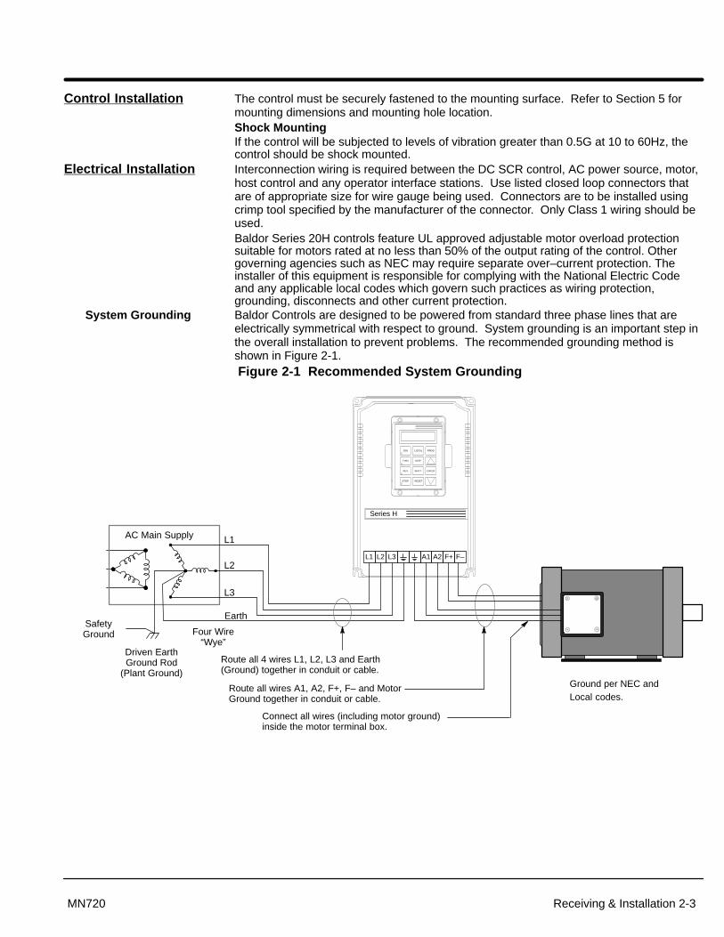
Control Installation The control must be securely fastened to the mounting surface. Refer to Section 5 formounting dimensions and mounting hole location.Shock MountingIf the control will be subjected to levels of vibration greater than 0.5G at 10 to 60Hz, thecontrol should be shock mounted.
Electrical Installation Interconnection wiring is required between the DC SCR control, AC power source, motor,host control and any operator interface stations. Use listed closed loop connectors thatare of appropriate size for wire gauge being used. Connectors are to be installed usingcrimp tool specified by the manufacturer of the connector. Only Class 1 wiring should beused.Baldor Series 20H controls feature UL approved adjustable motor overload protectionsuitable for motors rated at no less than 50% of the output rating of the control. Othergoverning agencies such as NEC may require separate over–current protection. Theinstaller of this equipment is responsible for complying with the National Electric Codeand any applicable local codes which govern such practices as wiring protection,grounding, disconnects and other current protection.
System Grounding Baldor Controls are designed to be powered from standard three phase lines that areelectrically symmetrical with respect to ground. System grounding is an important step inthe overall installation to prevent problems. The recommended grounding method isshown in Figure 2-1.Figure 2-1 Recommended System Grounding
L1
AC Main Supply
SafetyGround
Driven EarthGround Rod
(Plant Ground)
Four Wire“Wye”
L1
L2
L3
Earth
LOCAL
SHIFT
DISP
RESET
PROG
ENTER
JOG
STOP
REV
FWD
L2 L3 A1 A2
Series H
Route all 4 wires L1, L2, L3 and Earth(Ground) together in conduit or cable.
Route all wires A1, A2, F+, F– and MotorGround together in conduit or cable.
Connect all wires (including motor ground)inside the motor terminal box.
Ground per NEC and Local codes.
F+ F–

Section 1General Information
2-4 Receiving & Installation MN720
System Grounding Continued
Ungrounded Distribution SystemWith an ungrounded power distribution system it is possible to have a continuous currentpath to ground through the MOV devices. To avoid equipment damage, an Isolationtransformer with a grounded secondary is recommended. This provides three phase ACpower that is symmetrical with respect ground.
Input Power ConditioningBaldor controls are designed for direct connection to standard three phase lines that areelectrically symmetrical with respect to ground. Certain power line conditions must beavoided. An AC line reactor or an isolation transformer may be required for some powerconditions.
� Baldor Series H controls require a maximum line impedance of 5%. Refer to“Line Impedance” for additional information.
� If the feeder or branch circuit that provides power to the control haspermanently connected power factor correction capacitors, an input AC linereactor or an isolation transformer must be connected between the power factorcorrection capacitors and the control.
� If the feeder or branch circuit that provides power to the control has powerfactor correction capacitors that are switched on line and off line, the capacitorsmust not be switched while the control is connected to the AC power line. If thecapacitors are switched on line while the control is still connected to the ACpower line, additional protection is required. TVSS (Transient Voltage SurgeSuppressor) of the proper rating must be installed between the AC line reactoror an isolation transformer and the AC input to the control.
Line Impedance The Baldor Series 20H control requires a 5% maximum line impedance (voltage dropacross the reactor is 5% when the control draws rated input current). If the impedance ofthe incoming power does not meet the requirement for the control, a 3 phase line reactorcan be used to provide the needed impedance in most cases. Line reactors are optionaland are available from Baldor.
The input impedance of the power lines can be determined as follows:
Measure the line to line voltage at no load and at full rated load. Use these measured values to calculate impedance as follows:
%Impedance �(VoltsNo Load Speed � VoltsFull Load Speed)
(VoltsNo Load Speed)� 100
Line Reactors Three phase line reactors are available from Baldor. The line reactor to order is based onthe full load current of the motor (FLA). If providing your own line reactor, use thefollowing formula to calculate the minimum inductance required.
L �(VL�L � 0.03)
(I � 3� � 377) Where: L Minimum inductance in Henries.
VL-L Input volts measured line to line.0.03 Desired percentage of input impedance.I Input current rating of control.377 Constant used with 60Hz power.
Use 314 if input power is 50Hz.

Section 1General Information
Receiving & Installation 2-5MN720
Wiring Considerations
The DC control is self protected from normal AC line transients and surges. Additionalexternal protection may be required if high energy transients are present on the incomingpower source. These transients could be caused by sharing a power source with arcwelding equipment, large motors being started across the line, or other industrialequipment requiring large surge currents. To prevent damage due to power sourcedisturbances the following should be considered:
a) Connect the control on a feeder line separate from those supplying largeinductive loads.
b) Supply power to the control through a suitably sized isolation transformer.When using an isolation transformer to power the control, always switch thepower off and on between the transformer secondary and the control input toavoid spikes at the control when power is removed from the primary side.
All external signal wiring to the DC control should be run in a separate conduit from allother wiring. The use of shielded twisted pair wire is recommended for all signal wiring.The shield of the control wiring should be connected to analog ground of the DC controlonly. The other end of the shield should be taped to the wire jacket to prevent electricalshorts.
Wires for motor armature and fields may be run together in a conduit in accordance withNEC and local electrical codes and practices. For more information on wiringconsiderations, refer to “Electrical Noise Considerations” in Section 4 of this manual.

Section 1General Information
2-6 Receiving & Installation MN720
AC Main CircuitPower Disconnect A power disconnect should be installed between the input power service and the control for
a fail safe method to disconnect power. The control will remain in a powered-up condition untilall input power is removed from the control and the internal bus voltage is depleted.
Protection Devices Be sure a suitable input power protection device is installed. Use the recommended circuitbreaker or fuses listed in Tables 2-3 through 2-5 (Wire Size and Protection Devices). Referto ratings in Section 5 of this manual. If the output power from the control will be less thanthe maximum, the sizes of the wire and protective devices may be adjusted accordingly. Besure to follow NEC, UL and other applicable codes. Input and output wire size is based onthe use of copper conductor wire rated at 75 °C. The table is specified for NEMA B motors.
Circuit Breaker: 1 phase, thermal magnetic. Equal to GE type THQ or TEB for 230 VAC 3 phase, thermal magnetic. Equal to GE type THQ or TEB for 230 VAC or GE type TED for 460 VAC and 575 VAC.
Fast Action Fuses: 230 VAC, Buss KTN460 VAC, Buss KTS to 600A (KTU 601 - 1200A)575VAC, Buss FRS
Very Fast Action: 230 VAC, Buss JJN 460 VAC, Buss JJS575 VAC, Buss JJS
Time Delay Fuses: 230 VAC, Buss FRN 460 VAC, Buss FRS to 600A (KTU 601 - 1200A)575 VAC, Buss FRS to 600A (KLU 601 - 1200A)
Recommended fuse sizes are based on the following:115% of maximum continuous current for time delay fuses.150% of maximum continuous current for fast or very fast acting fuses.
Isolation Transformer Sizing
Use the information in Table 2-2 to select the KVA rating of the transformer based on theHP rating of the control. The secondary voltage will be the input voltage to the controland the impedance should be 5% or less.
One exception to Table 2-2 is when the DC armature voltage is less than the AC inputvoltage. If this is the case, use the following formula: KVA � 0.00163 � VACSecondary � IDCSecondary
Table 2-2 Isolation Transformer KVA Selection
HP 5 7.5 10 15 20 25 30 40 50 60 75 100 125 150 200 250 300KVA 7.5 11 14 20 27 34 40 51 63 75 93 118 145 175 220 275 330
Single Phase Power Since the control rectifies all three input power phases, operation from a single phasepower source is not possible.
Connections to an AC Generator Power Source
If a three phase motor driven generator set is to be used as the AC power source for theBaldor Control, the KVA rating of the generator should be at least 20 times the KVA ratingof the control.

Section 1General Information
Receiving & Installation 2-7MN720
Wire Sizes and Protective Devices
Table 2-3 Recommended Wire Size – 115VAC
MaximumOutput Fuse Wire Size
CatalogNumber
InputAmp
HP KW Armature & Buss AC Input Armature Output Field PowerSupplyHP KW AC Input Type AWG MM2 AWG MM2 AWG MM2
BC20H103–CL 16 3 2.2 50A, 500V FWH-50A 10 6 10 6 14 2.5BC20H107–CL 33 7 5.2 80A, 500V FWH-80A 6 16 6 16 14 2.5BC20H110–CL 49 10 7.5 100A, 500V FWH-100A 4 25 3 30 14 2.5BC20H115–CL 62 15 11.2 150A, 500V FWH-150A 3 30 2 35 14 2.5BC20H120–CL 82 20 14.9 150A, 500V FWH-150A 1 50 1/0 54 14 2.5BC20H125–CL 115 25 18.6 300A, 500V FWH-300A 1/0 54 2/0 70 14 2.5BC20H135–CL 148 35 26 350A, 500V FWH-350A 3/0 95 4/0 120 14 2.5BC20H140–CL 172 40 29.8 400A, 500V FWH-400A 4/0 120 300MCM 150 14 2.5BC20H150–CL 221 50 37.3 450A, 500V FWH-450A 300MCM 150 500MCM 240 14 2.5
Table 2-4 Recommended Wire Size – 230VAC
MaximumOutput Fuse Wire Size
CatalogNumber
InputAmp
HP KW Armature & Buss AC Input Armature Output Field PowerSupplyHP KW AC Input Type AWG MM2 AWG MM2 AWG MM2
BC20H205–CL 16 5 3.7 50A, 500V FWH-50A 10 6 10 6 14 2.5BC20H210–CL 33 10 7.5 80A, 500V FWH-80A 6 16 6 16 14 2.5BC20H215–CL 49 15 11.2 100A, 500V FWH-100A 4 25 3 30 14 2.5BC20H220–CL 62 20 14.9 150A, 500V FWH-150A 3 30 2 35 14 2.5BC20H225–CL 82 25 18.6 150A, 500V FWH-150A 1 50 1/0 54 14 2.5BC20H240–CL 115 40 29.8 300A, 500V FWH-300A 1/0 54 2/0 70 14 2.5BC20H250–CL 148 50 37.3 350A, 500V FWH-350A 3/0 95 4/0 120 14 2.5BC20H260–CL 172 60 44.8 400A, 500V FWH-400A 4/0 120 300MCM 150 14 2.5BC20H275–CL 221 75 56 400A, 500V FWH-400A 4/0 120 300MCM 150 14 2.5
BC20H2125–CL 182 125 93 600A, 500V FWP-600A (2)300MCM 150 (2)400MCM 200 14 2.5

Section 1General Information
2-8 Receiving & Installation MN720
Table 2-5 Recommended Wire Size – 460VAC
MaximumOutput Fuse Wire Size
CatalogNumber
InputAmp
HP KW Armature & Buss AC Input Armature Output Field PowerSupplyHP KW AC Input Type AWG MM2 AWG MM2 AWG MM2
BC20H410–CL 16 10 7.5 50A, 700V FWP-50A 10 6 10 6 14 2.5BC20H420–CL 33 20 14.9 80A, 700V FWP-80A 6 16 6 16 14 2.5BC20H430–CL 49 30 22.4 100A, 700V FWP-100A 4 25 3 30 14 2.5BC20H440–CL 62 40 29.8 150A, 700V FWP-150A 3 30 2 35 14 2.5BC20H450–CL 82 50 37.3 150A, 700V FWP-150A 1 50 1/0 54 14 2.5BC20H475–CL 115 75 56 300A, 700V FWP-300A 1/0 54 2/0 70 14 2.5
BC20H4100–CL 148 100 74.6 350A, 700V FWP-350A 3/0 95 4/0 120 14 2.5BC20H4125–CL 175 125 93 400A, 700V FWP-400A 4/0 120 300MCM 150 14 2.5BC20H4150–CL 221 150 112 400A, 700V FWP-400A 300MCM 150 500MCM 240 14 2.5BC20H4200–CL 287 200 149 600A, 700V FWP-600A (2) 300MCM 150 (2) 400MCM 200 14 2.5BC20H4250–CL 344 250 187 600A, 700V FWP-600A (2) 300MCM 150 (2) 400MCM 200 14 2.5BC20H4300–CL 410 300 224 800A, 700V FWP-800A (2) 400MCM 200 (2) 500MCM 240 14 2.5BC20H4400–CL 549 400 298 (2) 500A, 700V FWP-500A (3) 300MCM 150 (3) 500MCM 240 * (2) 18 0.75BC20H4500–CL 689 500 373 (2) 600A, 700V FWP-600A (3) 500MCM 240 (4) 400MCM 200 * (2) 18 0.75BC20H4600–CL 787 600 448 (2) 600A, 700V FWP-600A (4) 500MCM 240 (4) 500MCM 240 * (2) 18 0.75
* Wire size depends on the current required for motor.
Note: All wire sizes based on 75°C copper wire, 40°C ambient temperature, 4-6 conductors per conduit or racewayexcept as noted.
Note: Wire sizes shown above are for normal length power runs. Voltage drop to the motor and control should beconsidered. For longer power runs, use heavier gauge copper wire (within the size of the wire terminals).
Table 2-6 Fuses
Armature Input Wire (Copper) Field Power Output Wire (Copper)Standard Field Power Supply (15A) Buss KTK 20
High Capacity Field Power Supply (40A) Baldor V4360050 (Gould A70Q50)Reference/Supply Fuses Buss FNQ 2/10A

Section 1General Information
Receiving & Installation 2-9MN720
Figure 2-1 20H Enclosure Component Locations
��� ��� ��� ���
�� ��
� � � �
��� ��� ��
��� ���
���
Size AL3L2L1A2
GRD
J1 Terminal Strip
GND
A1
GND
A1
� � � �
���� ��� ��� ���
�� ��
��� ��� ��� ��� ��
Size B Size C
Size D
� � � �
� � � �
��� ��� ��� ���
�� ��
��� ��� ��� ��� ��
1 2 3
JP1
1 2 3
JP1
1 2 3
JP1
1 2 3
JP1
L3L2L1A2
J1 Terminal Strip
L3L2L1A2
L3L2L1A2
A1
A1
A1
J1 Terminal Strip
J1 Terminal Strip
Size G
A1
GND
L1 L2 L3
JP1 mounted oncontrol board(opposite side ofswing out panel).
A2
Blower
Blower

Section 1General Information
2-10 Receiving & Installation MN720
Three Phase Input Power Three phase AC power connections are shown in Figure 2-2.
Figure 2-2 Three Phase AC Power Connections
L1 L2 L3
Alternate *Fuse
ConnectionNote 1
L1 L2 L3
L1 L2 L3
* CircuitBreaker
Earth
* Optional components not provided with control.
Note 3
BaldorSeries HControl
*OptionalLine
Reactor
Note 1
Note 3
A1 B1 C1
A2 B2 C2
A1 B1 C1
Note 4Notes:
1. See “Protective Devices” described previously in this section.
2. Use same gauge wire for Earth ground as is used for L1, L2 and L3.
3. Metal conduit should be used. Connect conduits so the use of aReactor or RC Device does not interrupt EMI/RFI shielding.
4. See Line/Load Reactors described previously in this section.
Note 2
See Recommended Tightening Torques in Section 5.
Grounding by using conduit or panel connection is not adequate. A separateconductor of the proper size must be used as a ground conductor.
Cooling Fan Connection Some controls are equipped with cooling fans (pancake fans) or centrifugal blowerswhich must be connected to single phase power. 230VAC controls have 230VAC singlephase rated fans and 460VAC controls have 115VAC rated fans. Refer to the rating platelocated near the fan for voltage identification. Connect the proper single phase power tothe two fan terminals located on the side of the fan.
D size controls have a centrifugal blower that may be connected to either 230 or 460 voltAC single phase power. Connect the 230VAC or 460VAC to the blower as shown inFigure 2-3. The terminal block is located on the blower.
Figure 2-3 230VAC/460VAC Blower Connections (Single Phase)
Blue
Orange
Black
Red
TerminalBlock
CustomerSupplied230VAC
Blue
Orange
Black
Red
TerminalBlock
CustomerSupplied460VAC
Optional Field Power Module
Connection information is provided in “Interconnection Diagram” in Section 5 of thismanual.
Note: L1 and L2 inputs to the optional Field Power module are phase sensitive. Besure that the L1 input connects to L1 only and that the L2 input connects toL2 only, as shown in the diagram.

Section 1General Information
Receiving & Installation 2-11MN720
Motor Connections Motor connections are shown in Figure 2-4.
Note: If your motor requires more than 85% of the line voltage as its DC inputvoltage, a step up transformer is required. This is added between theincoming line terminals and the L1 and L2 terminals of the field supplymodule. This connection is phase sensitive with main input L1 and L2. The maximum input voltage to the field supply module is 528VAC @ 60Hz.
Figure 2-4 Motor Connections* Optional components not provided
with 20H Control.
See Recommended Tightening Torques in Section 5.
BaldorSeries HControl
Note 1
A1 A2
Notes:
1. Shield wires inside a metal conduit.
2. Metal conduit should be used to shield output wires (betweencontrol and motor). Connect conduits so the use of Load Reactoror RC Device does not interrupt EMI/RFI shielding.
3. Connect the field power supply leads of the DC motor to controlterminals F+ and F–. The standard field supply provides up to85% of the line voltage as its DC output voltage @ 15 amperes.A high capacity field power supply provides up to 85% of the linevoltage as its DC output voltage @ 40 amperes (see OptionalField Power Module described previously).
GRD
* DC Motor
F+ F–
F+ F–
* Typical shunt wound motor field connection120/240V or 150/300V. Consult manufacturersspecific motor data for details.
120V or150V
F1 F2
F3 F4
240V or 300V
F1 F4F2 F3
+
GRD
Note 2
Note 3
Note: The 20H control may be connected to a permanent magnet field DC motor.In this case, the field supply is not connected, the Level 2 Motor Data block,Motor Field parameter is set to PERM MAGNET, and the Level 1 FieldControl block, Field PWR Supply parameter is set to NONE.
M-Contactor If required by local codes or for safety reasons, an M-Contactor (motor circuit contactor)may be installed. However, incorrect installation or failure of the M-contactor or wiringmay damage the control. If an M-Contactor is installed, the control must be disabled forat least 20msec before the M-Contactor is opened or the control may be damaged.M-Contactor connections are shown in Figure 2-5.
Figure 2-5 Optional M–Contactor Connections
See Recommended Tightening Torques in Section 5.
* Optional RC DeviceElectrocubeRG1781-3
789
*M Enable
J1
* M-ContactorTo Customer Provided
Power Source (Rated Coil Voltage)
M=Contacts of optional M-Contactor
Note: Close “Enable” after “M” contact closure.
A1 A2 GND
* DC Motor
F+ F–
F+ F–
* M
+
*

2-12 Receiving & Installation MN720
M-Contactor Continued Control faults may occur if the control is enabled before the M Contactor is closed. Thetiming diagram shown in Figure 2-6 defines the correct operating sequence.
At Turn ONAllow 20 milli seconds for the coil of the M contactor to energize and close the contactorbefore the Enable input at J1-8 is issued.
At Turn OFFDo not allow the M Contactor to open until motor shaft rotation has stopped and theEnable at J1-8 has been removed. If this sequence does not occur, a TACH LOSS faultmay be issued by the control.
Note: This example shows a “Drive ON” output to a PLC that is used to commandthe 20H control and the holding brake.
Figure 2-6 M Contactor Operation Sequence
Turn-ON Run Time Turn-OFF
M Contact
Enable
20 msec.
Motor Flux
“Drive ON” Output
Mech. Brake Release(If user installed)
Speed/TorqueCommand
50 msec. Brake Set Time

Receiving & Installation 2-13MN720
External Trip Input Terminal J1-16 is available for connection to a normally closed customer supplied relay inall operating modes as shown in Figure 2-7. The thermostat contact should be a drycontact type with no power available from the contact. If the motor thermostat activates,the control will automatically disable and give an External Trip fault. When the motorcools sufficiently and the motor thermostat resets itself, the control may be restarted.
Connect the External Trip Input wires to J1-16 and J1-17. Do not place these wires in thesame conduit as the motor power leads.
To activate the External Trip input, the Level 2 Protection block, External Trip parametermust be set to “ON”.
Figure 2-7 Motor Temperature Relay
* Motor
1617
J1
External Trip
Do not run these wires in same conduitas motor leads or AC power wiring.
Customer ProvidedSource Voltage
Motor Thermostat Leads
CR1*
* Optional hardware. Must be ordered separately.
Note: Add appropriately rated protective device for AC relay (snubber)or DC relay (diode).
See recommended terminal tightening torques in Section 5.
Encoder Installation Electrical isolation of the encoder shaft and housing from the motor is required. Electricalisolation prevents capacitive coupling of motor noise that will corrupt the encoder signals.Baldor provides shielded wire for encoder connection. Figure 2-8 shows the electricalconnections between the encoder and the encoder connector.
Figure 2-8 Differential Encoder Connections
AABBCC+5VCOMMON
2324252627282930
J1
ElectricallyIsolatedEncoder
Single Ended ConnectionsDifferential inputs are recommended for best noise immunity. If only single endedencoder signals are available, connect them to A, B, and INDEX (C) (J1-23, J1-25 andJ1-27 respectively). A, B, and INDEX (C) are then connected to common at J1-30 asshown in Figure 2-9.
Figure 2-9 Single Ended Encoder Connections
AABBC INDEX (C)C INDEX (C)+5VCOMMON
2324252627282930
J1
ElectricallyIsolatedEncoder

2-14 Receiving & Installation MN720
Home (Orient) Switch InputThe Home or Orient function causes the motor shaft to rotate to a predefined homeposition. The home position is located when a machine mounted switch or the encoder“Index” pulse is activated (closed). Home is defined by a rising signal edge at terminalJ1-27. The shaft will continue to rotate only in a CW direction for a user defined offsetvalue. The offset is programmed in the Level 2 Miscellaneous Homing Offset parameter.The speed at which the motor will “Home” or orient is set with the Level 2 MiscellaneousHoming Speed parameter.
A machine mounted switch may be used to define the Home position in place of theencoder index channel. A differential line driver output from a solid state switch ispreferred for best noise immunity. Connect this differential output to terminals J1-27 andJ1-28.
A single ended solid-state switch or limit switch should be wired as shown in Figure 2-10.Regardless of the type of switch used, clean rising and falling edges at J1-27 are requiredfor accurate positioning.
Figure 2-10 Typical Home or Orient Switch Connections
27
28
29
30 Common+5V
INDEX
INDEX
J1
27
28
29
30 Common+5V
INDEX
INDEX
J1
Limit Switch (Closed at HOME).5VDC Proximity Switch
Terminal Tightening Torque = 7 Lb-in. (0.8 Nm).
+5V Input
Output
Common
Buffered Encoder Output The control provides a buffered encoder output on pins J1-31 to J1-38 as shown in Figure2-11. This output may be used by external hardware to monitor the encoder signals. It isrecommended that this output only drive one output circuit load.
Figure 2-11 Buffered Encoder Output
303132333435363738
29COMMON+5VDC
COMMON
AABBINDEXINDEXNot Used
BufferedEncoderOutput
26LS31
AABBCCDD
IN BIN CIN D
IN A
E E
FromProcessor
Terminal tightening torque is7 lb–in (0.8 Nm) maximum.
J1

Section 1General Information
Receiving & Installation 2-15MN720
Control Circuit Connections Eight operating modes are available. These modes define the basic motor controlsetup and the operation of the J1 input and output terminals. After the circuit connectionsare completed, the operating mode is selected by programming the Operating Modeparameter in the Level 1 Input programming Block. Available operating modes include:
• Keypad Control
• Standard Run, 3 Wire Control
• 15 Speed, 2 Wire Control
• Bipolar Speed or Torque
• Process Control
• Serial
• Bipolar Hoist
• 7 Speed Hoist
Each mode requires connections to the J1 terminal strip (except the keypad mode, allconnections are optional). The J1 terminal strip is shown in Figure 2-12. The connectionof each input or output signal is described in the following pages.
Figure 2-12 Control Signal Connections
�
�
��
��
��
��
��
��
��
�
��
��
��
��
��
Input #1
Input #2
Input #3
Input #4
Input #5
Input #6
Input #9
Opto In Common
J1
Analog GND
Analog Input 1
Pot Reference
Analog Input +2
Analog Input -2
Analog Out 1
Analog Out 2
Opto Out #1
Opto Out #2
Opto Out #3
Opto Out #4
�
�
�
�
�
�
See recommended terminal tightening torques in Section 5.
��
��
��
��
��
��
��
�
��
��
��
��
��
��
��
��
��
��
��
�
��
��
Common
+24VDC
A
A
B
B
INDEX
INDEX
+5VDC
Opto In Power
Opto Out #1 Return
Opto Out #2 Return
Opto Out #3 Return
Opto Out #4 Return
Common
A
A
B
B
INDEX
INDEX
Not Used
Refer to Encoder Installation
Refer to Buffered Encoder Output
Input #7
Input #8
Refer to opto isolated Outputs
Refer to opto isolated Inputs
Refer to Analog Outputs
Refer to Analog Inputs
Note: J1-18 and J1-41 are connected togetheron the control circuit board.
J1-39 & 40 Jumper as shown to power the opto inputs from the internal +24VDC supply.Opto Out #1 Return
2-16 Receiving & Installation MN720
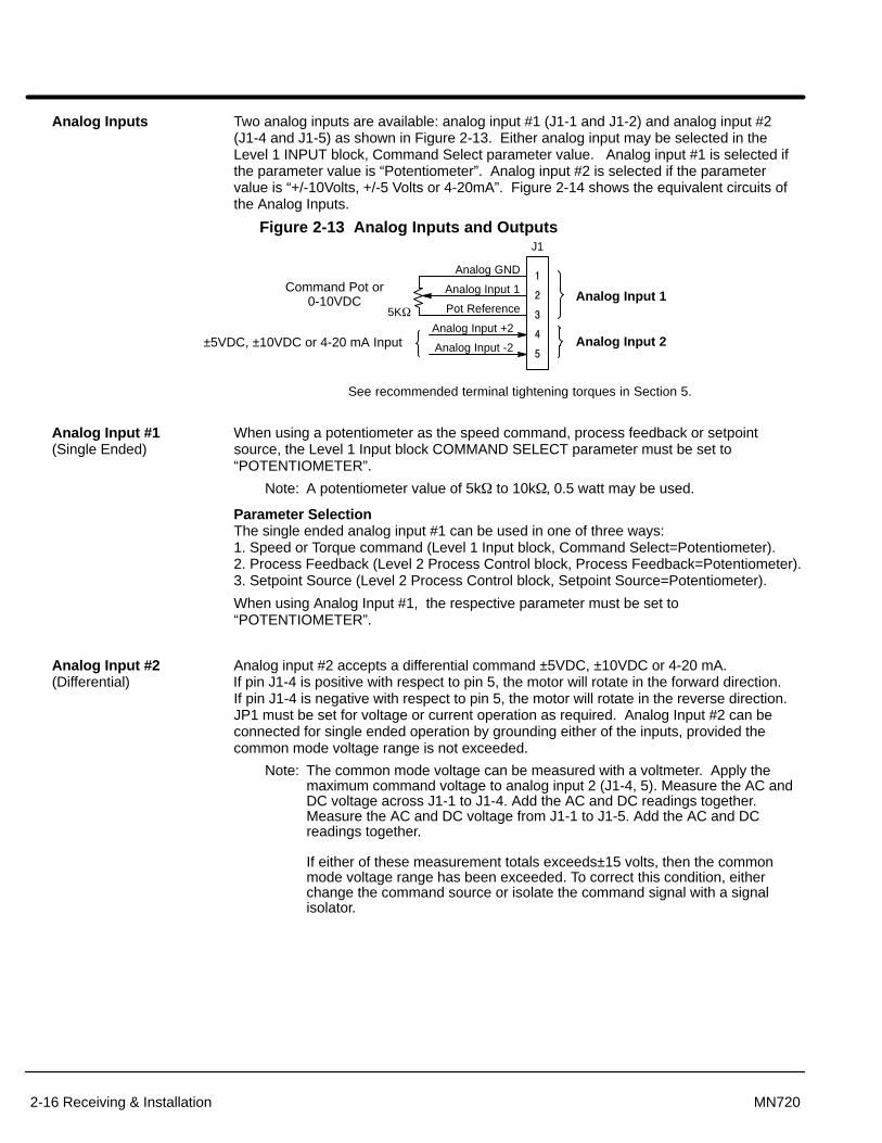
Analog Inputs Two analog inputs are available: analog input #1 (J1-1 and J1-2) and analog input #2(J1-4 and J1-5) as shown in Figure 2-13. Either analog input may be selected in theLevel 1 INPUT block, Command Select parameter value. Analog input #1 is selected ifthe parameter value is “Potentiometer”. Analog input #2 is selected if the parametervalue is “+/-10Volts, +/-5 Volts or 4-20mA”. Figure 2-14 shows the equivalent circuits ofthe Analog Inputs.
Figure 2-13 Analog Inputs and Outputs J1
Analog GND
Analog Input 1
Pot Reference
Analog Input +2
Analog Input -2
�
�
�
�
�
Analog Input 1
Analog Input 2
Command Pot or0-10VDC
±5VDC, ±10VDC or 4-20 mA Input
See recommended terminal tightening torques in Section 5.
5K�
Analog Input #1 When using a potentiometer as the speed command, process feedback or setpoint (Single Ended) source, the Level 1 Input block COMMAND SELECT parameter must be set to
“POTENTIOMETER”.
Note: A potentiometer value of 5k� to 10k�, 0.5 watt may be used.
Parameter SelectionThe single ended analog input #1 can be used in one of three ways: 1. Speed or Torque command (Level 1 Input block, Command Select=Potentiometer). 2. Process Feedback (Level 2 Process Control block, Process Feedback=Potentiometer).3. Setpoint Source (Level 2 Process Control block, Setpoint Source=Potentiometer).
When using Analog Input #1, the respective parameter must be set to“POTENTIOMETER”.
Analog Input #2 Analog input #2 accepts a differential command ±5VDC, ±10VDC or 4-20 mA. (Differential) If pin J1-4 is positive with respect to pin 5, the motor will rotate in the forward direction.
If pin J1-4 is negative with respect to pin 5, the motor will rotate in the reverse direction.JP1 must be set for voltage or current operation as required. Analog Input #2 can beconnected for single ended operation by grounding either of the inputs, provided thecommon mode voltage range is not exceeded.
Note: The common mode voltage can be measured with a voltmeter. Apply themaximum command voltage to analog input 2 (J1-4, 5). Measure the AC andDC voltage across J1-1 to J1-4. Add the AC and DC readings together.Measure the AC and DC voltage from J1-1 to J1-5. Add the AC and DCreadings together.
If either of these measurement totals exceeds±15 volts, then the commonmode voltage range has been exceeded. To correct this condition, eitherchange the command source or isolate the command signal with a signalisolator.

Receiving & Installation 2-17MN720
Figure 2-14 Analog Inputs Equivalent Circuits
����
–
+
5.1V Zener
.033 �F
5K�
1.96K�+15VDC
20K�
10K� 10K�
JP14-20mA +
–
X N/C
To Microprocessor
10K� 10K�
To Microprocessor
Notes: +
–All OP Amps are TL082 or TL084
Analog Ground is separated from Chassis Ground. Electrically theyare separated by an RC network.
30K�
-15VDCJ1
2
3
4
5
1
See recommended terminal tightening torques in Section 5.
Analog Outputs Two programmable analog outputs are provided on J1-6 and J1-7. See Figure 2-15.These outputs are scaled 0 - 5 VDC (1mA maximum output current) and can be used toprovide real-time status of various control conditions. The output conditions are definedin Section 4 of this manual.
The return for these outputs is J1-1 analog ground. Each output is programmed in theLevel 1 Output block.
Figure 2-15 Analog Outputs Equivalent Circuits
+
–
10K�
10K�
.033 �f
50�6
From Microprocessor
+
–
10K�
10K�
.033 �f
50�7
From Microprocessor
Notes:
+
–All OP Amps are TL082 or TL084
Analog Ground is separated from Chassis Ground. Electrically theyare separated by an RC network.
1
See recommended terminal tightening torques in Section 5.
J1

2-18 Receiving & Installation MN720
Serial Operating Mode The Serial operating mode requires one of the optional Serial Interface expansion boards(RS232, RS422 or RS485). Installation and operation information for these serialexpansion boards is provided in Serial Communications expansion board manualMN1310. This manual is shipped with the serial expansion boards.
Keypad Operating Mode The Keypad operating mode allows the control to be operated from the keypad. Thismode requires no connections to J1. However, the External Trip input may optionally beused. All other opto inputs remain inactive. The analog outputs and opto-outputs remainactive at all times.
Parameter SelectionFor operation in Keypad mode, set the Level 1 Input block, Operating Mode parameter toKeypad. The STOP key can operate in two ways:
� Press STOP key one time to brake or coast to stop.
� Press STOP key two times to disable control.
The External Trip input causes a fault condition during a motor over temperaturecondition (when normally closed input opens). The External Trip input (J1-16) must beconnected and the External Trip parameter in the Level 2 Protection block must be set to“ON”. When J1-16 is opened, an external trip fault occurs. The control will disable andthe motor coasts to a stop. An external trip fault is displayed on the keypad display (alsologged into the fault log).
Figure 2-16 Keypad Control Connection Diagram
Programmable Output
No Connection
See recommended terminal tightening torques in Section 5.
Refer to Figure 2-7.
�
�
��
��
��
��
��
��
��
�
Input #1
Input #2
Input #3
Input #4
Input #5
Input #6
Input #9
Opto In Common
Analog GND
Analog Input 1
Pot Reference
Analog Input +2
Analog Input -2
Analog Out 1
Analog Out 2
�
�
�
�
�
�
Input #7
Input #8
J1
Programmable Output
J1-16 If J1-16 is connected, you must set Level 2 Protection block, External Trip to“ON” to activate the opto input.CLOSED allows normal operation.OPEN causes an external trip fault. The control will disable and the motorcoasts to a stop. An external trip fault is displayed (also logged in the fault log).
External Trip
No Connection

Section 1General Information
Receiving & Installation 2-19MN720
Standard Run 3 Wire Mode ConnectionsIn Standard Run mode, the control is operated by the opto Isolated inputs at J1-8 throughJ1-16 and the analog command input. The opto inputs can be switches as shown inFigure 2-17 or logic signals from another device. The External Trip opto input at J1-16 isactive if connected as shown and the Level 2 Protection block, External Trip parameter isset to ON.
Figure 2-17 Standard Run 3-Wire Connection Diagram
See recommended terminal tightening torques in Section 5.
�
�
��
��
��
��
��
��
��
�
Enable
Forward Run
Reverse Run
Stop
Jog
Accel/Decel
External Trip
Opto In Common
Analog GND
Analog Input 1
Pot Reference
Analog Input +2
Analog Input -2
Analog Out 1
Analog Out 2
�
�
�
�
�
�
Preset Speed #1
Fault Reset
J1
Refer to Figure 2-7.
Programmable Output
Programmable Output
J1-8 CLOSED allows normal operation.OPEN disables the control and motor coasts to a stop.
J1-9 MOMENTARY CLOSED starts motor operation in the Forward direction. InJOG mode (J1-12 CLOSED), continuous CLOSED jogs motor in the Forwarddirection.
J1-10 MOMENTARY CLOSED starts motor operation in the Reverse direction. InJOG mode (J1-12 CLOSED), CONTINUOUS closed JOGS motor in theReverse direction.
J1-11 MOMENTARY OPEN motor decels to stop (depending on Keypad Stopmode).
J1-12 CLOSED places control in JOG mode, Forward and Reverse run are used tojog the motor.
J1-13 CLOSED selects ACC / DEC / S-CURVE group 2.OPEN selects ACC / DEC / S-CURVE group 1.
J1-14 CLOSED selects preset speed #1, (J1-12, will override this preset speed).OPEN allows speed command from Analog input #1 or #2.
J1-15 CLOSED to reset fault condition.OPEN to run.
J1-16 If J1-16 is connected, you must set Level 2 Protection block, External Trip to“ON” to activate the opto input.CLOSED allows normal operation.OPEN causes an external trip fault. The control will disable and the motorcoasts to a stop. An external trip fault is displayed (also logged in the fault log).
Command Pot or0-10VDC
5K�
Section 1General Information
2-20 Receiving & Installation MN720
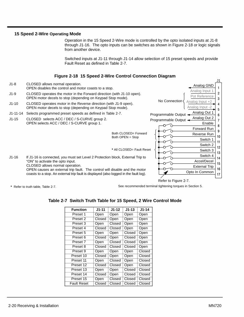
15 Speed 2-Wire Operating ModeOperation in the 15 Speed 2-Wire mode is controlled by the opto isolated inputs at J1-8through J1-16. The opto inputs can be switches as shown in Figure 2-18 or logic signalsfrom another device.
Switched inputs at J1-11 through J1-14 allow selection of 15 preset speeds and provideFault Reset as defined in Table 2-7.
Figure 2-18 15 Speed 2-Wire Control Connection Diagram
See recommended terminal tightening torques in Section 5.
�
�
��
��
��
��
��
��
��
�
Enable
Forward Run
Reverse Run
Switch 1
Switch 2
Switch 3
External Trip
Opto In Common
Analog GND
Analog Input 1
Pot Reference
Analog Input +2
Analog Input -2
Analog Out 1
Analog Out 2
�
�
�
�
�
�
Switch 4
Accel/Decel
J1
Refer to Figure 2-7.
Programmable Output
Programmable Output
J1-8 CLOSED allows normal operation.OPEN disables the control and motor coasts to a stop.
J1-9 CLOSED operates the motor in the Forward direction (with J1-10 open). OPEN motor decels to stop (depending on Keypad Stop mode).
J1-10 CLOSED operates motor in the Reverse direction (with J1-9 open). OPEN motor decels to stop (depending on Keypad Stop mode).
J1-11-14 Selects programmed preset speeds as defined in Table 2-7.
J1-15 CLOSED selects ACC / DEC / S-CURVE group 2.OPEN selects ACC / DEC / S-CURVE group 1.
J1-16 If J1-16 is connected, you must set Level 2 Protection block, External Trip to“ON” to activate the opto input.CLOSED allows normal operation.OPEN causes an external trip fault. The control will disable and the motorcoasts to a stop. An external trip fault is displayed (also logged in the fault log).
No Connection
Both CLOSED= ForwardBoth OPEN = Stop
* Refer to truth table, Table 2-7.
* All CLOSED= Fault Reset
Table 2-7 Switch Truth Table for 15 Speed, 2 Wire Control Mode
Function J1-11 J1-12 J1-13 J1-14Preset 1 Open Open Open OpenPreset 2 Closed Open Open OpenPreset 3 Open Closed Open OpenPreset 4 Closed Closed Open OpenPreset 5 Open Open Closed OpenPreset 6 Closed Open Closed OpenPreset 7 Open Closed Closed OpenPreset 8 Closed Closed Closed OpenPreset 9 Open Open Open Closed
Preset 10 Closed Open Open ClosedPreset 11 Open Closed Open ClosedPreset 12 Closed Closed Open ClosedPreset 13 Open Open Closed ClosedPreset 14 Closed Open Closed ClosedPreset 15 Open Closed Closed Closed
Fault Reset Closed Closed Closed Closed

Receiving & Installation 2-21MN720
Bipolar Speed or Torque Operating ModeProvides bipolar speed or torque control. Also, you may store up to two complete sets ofoperating parameters. This is important if you wish to store and use different accelerationrates, speed commands, jog speeds or to store tuning parameter values for differentmotors etc. The opto inputs can be switches as shown in Figure 2-19 or logic signals fromanother device.
Figure 2-19 Bipolar Speed or Torque Connection Diagram
See recommended terminal tightening torques in Section 5.
�
�
��
��
��
��
��
��
��
�
Enable
Forward Enable
Reverse Enable
Homing
Speed/Torque
Switch 1
External Trip
Opto In Common
Analog GND
Analog Input 1
Pot Reference
Analog Input +2
Analog Input -2
Analog Out 1
Analog Out 2
�
�
�
�
�
�
Fault Reset
J1
Refer to Figure 2-7.
Programmable Output
Programmable Output
J1-8 CLOSED allows normal operation.OPEN disables the control & motor coasts to a stop.
J1-9 CLOSED to enable operation in the Forward direction. OPEN TO DISABLE Forward operation (drive will brake to a stop if a Forward command is still present). Reverse operation is still possible if J1-10 is closed.
J1-10 CLOSED to enable operation in the Reverse direction. OPEN to disable Reverse operation (drive will brake to a stop if a Reverse command is still present). Forward operation is still possible if J1-9 is closed.
Note: If J1-9 and J1-10 are both opened, the drive will brake to a stop.
J1-11 CLOSED causes the motor to rotate in the forward direction until the load reaches a marker or external switch location.OPEN allows normal operation.
J1-12 CLOSED puts the control in torque (current) command mode. OPEN puts the control in speed (velocity) command mode.
J1-13 Select from the parameter tables defined in Table 2-8.
J1-15 Momentary CLOSED to reset fault condition.OPEN allows normal operation.
J1-16 If J1-16 is connected, you must set Level 2 Protection block, External Trip to“ON” to activate the opto input.CLOSED allows normal operation.OPEN causes an external trip fault. The control will disable and the motorcoasts to a stop. An external trip fault is displayed (also logged in the fault log).
5K�
Command Pot or0-10VDC
Continued on next page
Section 1General Information
2-22 Receiving & Installation MN720
Multiple Parameter SetsThe following procedure allows you to program up to two complete sets of parametervalues and to use these multiple parameter sets. When programming each parameterset, use the ENTER key to accept and automatically save parameter values.
Note: Preset speed does not apply to table select.
Note: Except for the Level 1 Operating Mode parameter, the control can beprogrammed in the REMOTE mode with the drive enabled and switches instep 4 closed. The control must be disabled to change the operating modeparameter.
1. Set the Level 1 INPUT block, Operating Mode parameter value to BIPOLAR ineach of the parameter sets.
2. Open switch J1-13. Be sure switches J1-9 and J1-10 are OPEN, J1-8 isCLOSED. Enter all parameter values, and autotune as instructed in Section 3of this manual. This creates and saves the first parameter set which isnumbered Table#0.
3. Close switch J1-13. Be sure switches J1-9 and J1-10 are OPEN, J1-8 isCLOSED. Enter all parameter values, and autotune as instructed in Section 3of this manual. This creates and saves the second parameter set which isnumbered Table#1.
4. Program the parameter values for each table. Remember that to change thevalue of a parameter in one of the parameter tables, you must first select thetable using switch J1–13. You cannot change a value in a table until you havefirst selected that table.
Note: Table#0 must contain the greater of the two MAX SPEED parameters. Thecontrol always starts in Table#0.
Table 2-8 Bipolar Mode Table Select Truth Table
Function J1-13
Parameter Table #0 Open
Parameter Table #1 Closed
Note: All parameters except operating mode can be changed and saved for eachtable.
Note: Preset speed does not apply to table select.

Receiving & Installation 2-23MN720
Process Operating Mode
Figure 2-20 Process Mode Connection Diagram
See recommended terminal tightening torques in Section 5.
�
�
��
��
��
��
��
��
��
�
Enable
Forward Enable
Reverse Enable
Table Select
Speed/Torque
Process Mode Enable
External Trip
Opto In Common
Analog GND
Analog Input 1
Pot Reference
Analog Input +2
Analog Input -2
Analog Out 1
Analog Out 2
�
�
�
�
�
�
Jog
Fault Reset
J1
Refer to Figure 2-7.
Programmable Output
Programmable Output
J1-8 CLOSED allows normal operation.OPEN disables the control & motor coasts to a stop.
J1-9 CLOSED to enable operation in the Forward direction. OPEN TO DISABLE Forward operation (drive will brake to a stop if a Forwardcommand is still present). Reverse operation is still possible if J1-10 is closed.
J1-10 CLOSED to enable operation in the Reverse direction. OPEN to disable Reverse operation (drive will brake to a stop if a Reversecommand is still present). Forward operation is still possible if J1-9 is closed.
Note: If J1-9 and J1-10 are both opened, the drive will brake to a stop.
J1-11 CLOSED = TABLE 1, OPEN = TABLE 0. (See multiple parameter sets.)
J1-12 CLOSED, the control is in torque (current) command mode. OPEN, the control is in speed (velocity) command mode.
J1-13 CLOSED to enable the Process Mode.
J1-14 CLOSED places control in JOG mode. The control will only JOG in the forwarddirection.
J1-15 CLOSED to reset a fault condition.OPEN to run.
J1-16 If J1-16 is connected, you must set Level 2 Protection block, External Trip to “ON”to activate the opto input.CLOSED allows normal operation.OPEN causes an external trip fault. The control will disable and the motor coaststo a stop. An external trip fault is displayed (also logged in the fault log).
5K�
Command Pot or0-10VDC
Table 2-9 Process Mode Input Signal Compatibility
FeedbackSetpoint or
Feedforward J1-1 & 2 J1-4 & 5 5V EXB� 10V EXB�4-20mAEXB�
3-15 PSIEXB�
DC Tach EXB�
J1-1 & 2J1-4 & 55V EXB� ËËËËË10V EXB�
ËËËËËËËËËË4-20mA EXB� ËËËËËËËËËË3-15 PSI EXB� ËËËËË
ËËËËËËËËËËËËËËË
ËËËËËËËËËËDC Tach EXB�
EXB PULSE FOL � � ËËËËËSerial � �
ËËËËËËËËËË
ËËËËËËËËËË
ËËËËËËËËËË
ËËËËËËËËËË
� Requires expansion board EXB007A01 (High Resolution Analog I/O EXB).� Requires expansion board EXB004A01 (4 Output Relays/3-15 PSI Pneumatic Interface EXB).� Requires expansion board EXB006A01 (DC Tachometer Interface EXB).
� Requires expansion board EXB005A01 (Master Pulse Reference/Isolated Pulse Follower EXB).� Used for Feedforward only. Must not be used for Setpoint Source or Feedback.
� Requires expansion board EXB001A01 (RS232 Serial Communication EXB). orRequires expansion board EXB002A01 (RS422/RS485 High Speed Serial Communication EXB).
Conflicting inputs. Do not use same input signal multiple times.ËËËËËË
Conflicting level 1 or 2 expansion boards. Do not use!

Section 1General Information
2-24 Receiving & Installation MN720
Bipolar Hoist Mode ConnectionsThis mode of operation allows the user to store two (2) complete sets of operatingparameters for hoist operation. Table 2-10 shows switch settings required to access eachparameter table. When programming each parameter set, use the ENTER key to acceptand automatically save parameter values.
Note: Except for the Level 1 Operating Mode parameter, the control can beprogrammed in the REMOTE mode with the drive enabled and switches instep 4 closed. The control must be disabled to change the operating modeparameter.
1. Set the Level 1 INPUT block, Operating Mode parameter value to BIPOLAR ineach of the parameter sets.
2. Open switch J1-13. Be sure switches J1-9 and J1-10 are OPEN, J1-8 isCLOSED. Enter all parameter values, and autotune as instructed in Section 3of this manual. This creates and saves the first parameter set which isnumbered Table#0.
3. Close switch J1-13. Be sure switches J1-9 and J1-10 are OPEN, J1-8 isCLOSED. Enter all parameter values, and autotune as instructed in Section 3of this manual. This creates and saves the second parameter set which isnumbered Table#1.
4. Remember that to change the value of a parameter in one of the parametertables, you must first select the table using switch J1–13. You cannot change avalue in a table until you have first selected that table.
Note: Table#0 must contain the greater of the two MAX SPEED parameters. Thecontrol always starts in Table#0.
Table 2-10 Bipolar Mode Table Select Truth Table
Function J1-13
Parameter Table #0 Open
Parameter Table #1 Closed
Note: All parameters except operating mode can be changed and saved for eachtable.
Note: Preset speed does not apply to table select.

Section 1General Information
Receiving & Installation 2-25MN720
Figure 2-21 Bipolar Hoist Connection Diagram
See recommended terminal tightening torques in Section 5.
�
�
��
��
��
��
��
��
��
�
Enable
Forward Enable
Reverse Enable
Orient
Speed/Torque
Table Select
External Trip
Opto In Common
Analog GND
Analog Input 1
Pot Reference
Analog Input +2
Analog Input -2
Analog Out 1
Analog Out 2
�
�
�
�
�
�
Fault Reset
J1
Refer to Figure 2-7.
Programmable Output
Programmable Output
J1-8 CLOSED allows normal operation.OPEN disables the control & motor coasts to a stop.
J1-9 CLOSED to enable operation in the Forward direction. OPEN TO DISABLE Forward operation (drive will brake to a stop if a Forwardcommand is still present). Reverse operation is still possible if J1-10 is closed.
J1-10 CLOSED to enable operation in the Reverse direction. OPEN to disable Reverse operation (drive will brake to a stop if a Reversecommand is still present). Forward operation is still possible if J1-9 is closed.
Note: If J1-9 and J1-10 are both opened, the drive will brake to a stop.
J1-11 CLOSED causes the motor to rotate in the forward direction until the loadreaches a marker or external switch location.OPEN allows normal operation.
J1-12 CLOSED puts the control in torque (current) command mode. OPEN puts the control in speed (velocity) command mode.
J1-13 Select from the parameter tables defined in Table 2-11.
J1-15 Momentary CLOSED to reset fault condition.OPEN allows normal operation.
J1-16 If J1-16 is connected, you must set Level 2 Protection block, External Trip to“ON” to activate the opto input.CLOSED allows normal operation.OPEN causes an external trip fault. The control will disable and the motorcoasts to a stop. An external trip fault is displayed (also logged in the fault log).
5K�
Command Pot or0-10VDC
Table 2-11 Bipolar Mode Table Select Truth Table
Function J1-13
Parameter Table #0 Open
Parameter Table #1 Closed

Section 1General Information
2-26 Receiving & Installation MN720
7 Speed Hoist, 2-Wire Mode Connections Switch Truth Table is defined in Table 2-12.
Operation in the 15 Speed 2-Wire mode is controlled by the Opto Isolated inputs at J1-8through J1-16. The Opto inputs can be switches as shown in Figure 2-22 or logic signalsfrom another device. The External Trip Opto Input at J1-16 is active if connected asshown and the Level 2 Protection block, External Trip parameter is set to ON.
Switched inputs at J1-11 through J1-13 allow selection of 7 preset speeds for Hoistoperation and provide Fault Reset as defined in Table 2-12.
Table 2-12 Switch Truth Table for 15 Speed, 2 Wire Control Mode
Function J1-11 J1-12 J1-13Preset 1 Open Open OpenPreset 2 Closed Open OpenPreset 3 Open Closed OpenPreset 4 Closed Closed OpenPreset 5 Open Open ClosedPreset 6 Closed Open ClosedPreset 7 Open Closed Closed
Fault Reset Closed Closed Closed
Figure 2-22 7 Speed Hoist, 2-Wire Mode Connection Diagram
See recommended terminal tightening torques in Section 5.
�
�
��
��
��
��
��
��
��
�
Enable
Forward Run
Reverse Run
* Switch 1
* Switch 2
* Switch 3
External Trip
Opto In Common
Analog Out 1
Analog Out 2
�
�
�
�
�
�
Field Enable
ACC/DEC/“S” Select 1
J1
Refer to Figure 2-7.
Programmable Output
Programmable Output
J1-8 CLOSED allows normal operation.OPEN disables the control and motor coasts to a stop.
J1-9 CLOSED starts motor operation in the Forward direction. OPEN motor decels to stop (depending on Keypad Stop mode).
J1-10 CLOSED starts motor operation in the Reverse direction. OPEN motor decels to stop (depending on Keypad Stop mode).
Note: Closing both J1-9 and J1-10 at the same time will reset a fault condition.
J1-11 Selects preset speeds as defined in the Speed Select Table (Table 2-12).
J1-12 Selects preset speeds as defined in the Speed Select Table (Table 2-12).
J1-13 Selects preset speeds as defined in the Speed Select Table (Table 2-12).
J1-14 CLOSED allows the field to be energized prior to armature enable. This provides torque instantly when armature is enabled.
J1-15 CLOSED selects ACC / DEC / S-CURVE group 2.OPEN selects ACC / DEC / S-CURVE group 1.
J1-16 If J1-16 is connected, you must set Level 2 Protection block, External Trip to“ON” to activate the opto input.CLOSED allows normal operation.OPEN causes an external trip fault. The control will disable and the motorcoasts to a stop. An external trip fault is displayed (also logged in the fault log).
Analog GND
Analog Input 1
Pot Reference
Analog Input +2
Analog Input -2
No Connection
* See Table 2-12.

Receiving & Installation 2-27MN720
Opto-Isolated Inputs The equivalent circuit of the nine opto inputs is shown in Figure 2-23. The function ofeach input depends on the operating mode selected and are described previously in thissection. This Figure also shows the connections using the internal opto input Supply.
Figure 2-23 Opto-Input Connections (Using Internal Supply)
See recommended terminal tightening torques in Section 5.
+24VDC @ 200mA (supply terminal 39).
Jumper terminals 39 to 40(Factory Installed)
6.8K 6.8K 6.8K 6.8K 6.8K 6.8K 6.8K 6.8K 6.8K
��
��
�
��
��
Opto In #8
Opto In #9
Opto In Common
�
�
��
��
��
��
��
J1
Opto In #1
Opto In #2
Opto In #3
Opto In #4
Opto In #5
Opto In #6
Opto In #7
Figure 2-24 Opto-Input Connections (Using External Supply)
See recommended terminal tightening torques in Section 5.* User VCC = 10 - 30VDC External Power Source
* User VCC (-)
* User VCC (+)
Opto Inputs Closing to Ground Opto Inputs Closing to +VCC
��
��
�
��
��
Opto In #8
Opto In #9
�
�
��
��
��
��
��
J1
Opto In #1
Opto In #2
Opto In #3
Opto In #4
Opto In #5
Opto In #6
Opto In #7
* User VCC (+)
* User VCC (-)
��
��
�
��
��
Opto In #8
Opto In #9
�
�
��
��
��
��
��
J1
Opto In #1
Opto In #2
Opto In #3
Opto In #4
Opto In #5
Opto In #6
Opto In #7
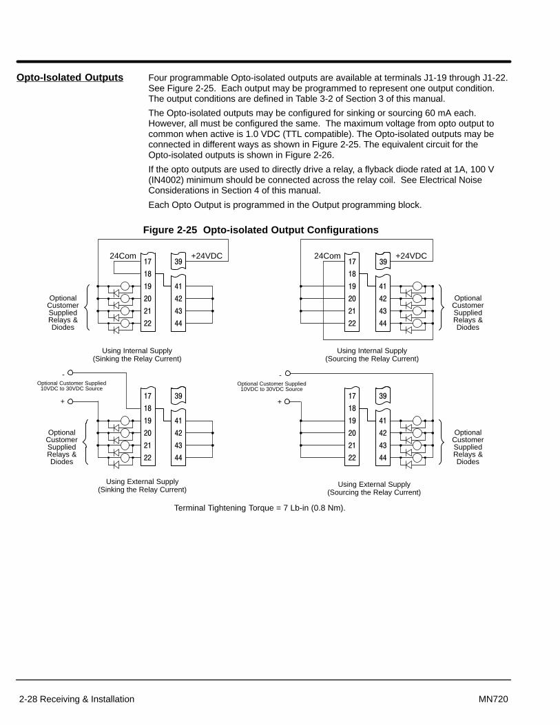
Section 1General Information
2-28 Receiving & Installation MN720
Opto-Isolated Outputs Four programmable Opto-isolated outputs are available at terminals J1-19 through J1-22.See Figure 2-25. Each output may be programmed to represent one output condition.The output conditions are defined in Table 3-2 of Section 3 of this manual.
The Opto-isolated outputs may be configured for sinking or sourcing 60 mA each.However, all must be configured the same. The maximum voltage from opto output tocommon when active is 1.0 VDC (TTL compatible). The Opto-isolated outputs may beconnected in different ways as shown in Figure 2-25. The equivalent circuit for theOpto-isolated outputs is shown in Figure 2-26.
If the opto outputs are used to directly drive a relay, a flyback diode rated at 1A, 100 V(IN4002) minimum should be connected across the relay coil. See Electrical NoiseConsiderations in Section 4 of this manual.
Each Opto Output is programmed in the Output programming block.
Figure 2-25 Opto-isolated Output Configurations
Using Internal Supply(Sinking the Relay Current)
OptionalCustomerSuppliedRelays &Diodes
Using Internal Supply(Sourcing the Relay Current)
Using External Supply(Sinking the Relay Current)
Using External Supply(Sourcing the Relay Current)
Optional Customer Supplied10VDC to 30VDC Source
�
��
��
��
��
��
24Com��
��
��
��
��
+24VDC
OptionalCustomerSuppliedRelays &Diodes
�
��
��
��
��
��
��
��
��
��
��
+
-
OptionalCustomerSuppliedRelays &Diodes
�
��
��
��
��
��
24Com
��
��
��
��
+24VDC
OptionalCustomerSuppliedRelays &Diodes
�
��
��
��
��
��
��
��
��
��
��
Optional Customer Supplied10VDC to 30VDC Source
+
-
��
Terminal Tightening Torque = 7 Lb-in (0.8 Nm).
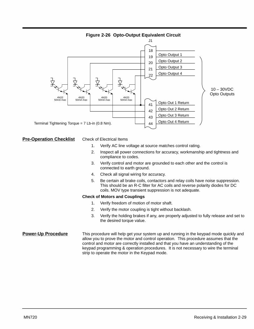
Section 1General Information
Receiving & Installation 2-29MN720
Figure 2-26 Opto-Output Equivalent Circuit
19
20
21
22
41
42
43
Opto Output 1
Opto Output 2
Opto Output 3
Opto Output 4
Opto Out 1 Return
J1
Terminal Tightening Torque = 7 Lb-in (0.8 Nm).
Opto Out 2 Return
Opto Out 3 Return
44 Opto Out 4 Return
18
4N3350mA max
4N3350mA max
4N3350mA max
4N3350mA max
10 – 30VDCOpto Outputs
Pre-Operation Checklist Check of Electrical Items
1. Verify AC line voltage at source matches control rating.
2. Inspect all power connections for accuracy, workmanship and tightness andcompliance to codes.
3. Verify control and motor are grounded to each other and the control isconnected to earth ground.
4. Check all signal wiring for accuracy.
5. Be certain all brake coils, contactors and relay coils have noise suppression.This should be an R-C filter for AC coils and reverse polarity diodes for DCcoils. MOV type transient suppression is not adequate.
Check of Motors and Couplings
1. Verify freedom of motion of motor shaft.
2. Verify the motor coupling is tight without backlash.
3. Verify the holding brakes if any, are properly adjusted to fully release and set tothe desired torque value.
Power-Up Procedure This procedure will help get your system up and running in the keypad mode quickly andallow you to prove the motor and control operation. This procedure assumes that thecontrol and motor are correctly installed and that you have an understanding of thekeypad programming & operation procedures. It is not necessary to wire the terminalstrip to operate the motor in the Keypad mode.
Section 1General Information
2-30 Receiving & Installation MN720
Initial ConditionsBe sure the control and motor are wired according to the procedures described previouslyin this section. Become familiar with the keypad programming and keypad operation of thecontrol as described in Section 3 of this manual.
1. Verify that any enable inputs to J1-8 are open.
2. Turn power on. Be sure there are no faults.
3. Set the Level 1 Input block, Operating Mode to “KEYPAD”.
4. Enter the following motor data in the Level 2 Motor Data block parameters:Armature VoltageARM Rated AmpsMotor Rated SpeedMotor Field (Shunt or Permanent Magnet)Motor Field VoltsMotor Field Amps
5. Set the feedback type to Armature, Encoder, Resolver or Tachometer in theLevel 2 Motor Data block, Feedback Type parameter.
6. If feedback type is Armature, skip this step.If Encoder, Tachometer or Resolver feedback type was selected, set one of thefollowing corresponding Level 2 Motor Data block parameters: Encoder Counts (ppr)Resolver SpeedTachometer Volts (VDC per 1000 RPM)
WARNING: The motor shaft will rotate during this procedure. Be certain thatunexpected motor shaft movement will not cause injury topersonnel or damage to equipment.
7. Go to Level 2 Autotune block, press ENTER, at CALC PRESETS select YES(using the key) and let the control calculate preset values for the parametersthat are necessary for control operation.
8. Disconnect all input power.
9. Disconnect the motor from the load (including coupling or inertia wheels). If theload cannot be disconnected, do not perform the Feedback tests in step 11.
10. Connect input power.
11. Go to Level 2 Autotune block, and do the following tests:CMD OFFSET TRIMCUR LOOP COMPFEEDBACK TESTS (Only if load is disconnected)
12. Set the Level 2 Output Limits block, “MIN OUTPUT SPEED” parameter.
13. Set the Level 2 Output Limits block, “MAX OUTPUT SPEED” parameter.
14. Disconnect all input power.
15. Couple the motor to its load.
16. Connect input power.
17. Go to Level 2 Autotune block, and perform the SPD CNTRLR CALC test.
18. Run the drive from the keypad using one of the following: the arrow keys fordirect speed control, a keypad entered speed or the JOG mode.
19. Select additional parameters to customize the control to the application (MAXSPEED, etc.).
The control is now ready for use the in keypad mode. If a different operating mode is desired,refer to Section 3 Control Connections and Section 4 Programming and Operation.

Section 3Programming and Operation
Programming & Operation 3-1MN720
Overview The keypad is used to program the control parameters, operate the motor and monitorthe status and outputs of the control by accessing the display options, diagnostic menusand the fault log.
Figure 3-1 Keypad JOG - (Green) lights when Jog is active.FWD - (Green) lights when FWD direction is commanded.REV - (Green) lights when REV direction is commanded.STOP - (Red) lights when motor STOP is commanded.Indicator Lights
Keypad Display - Displays statusinformation during Local or Remoteoperation. It also displays informationduring parameter setup and fault orDiagnostic Information.
JOG - Press JOG to select thepreprogrammed jog speed. After the jogkey has been pressed, use the FWD orREV keys to run the motor in thedirection that is needed. The JOG key isonly active in the local mode.
FWD - Press FWD to initiate forwardrotation of the motor. This key is onlyactive in the Keypad or local mode.
REV - Press REV to initiate reverserotation of the motor. This key is activeonly in the Keypad or local mode.
STOP - Press STOP one time to initiatea stop sequence. Depending on thesetup of the control, the motor will eitherramp or coast to a stop. This key isoperational in all modes of operationunless it has been disabled by theKeypad Stop parameter in the Keypad(programming) Setup Block. Press STOPtwice to disable control (coast to stop).
Note: If the control is operating inremote mode and the stop key ispressed the control will change tothe local mode when the stopcommand is initiated. To resumeoperation in the remote mode,press the LOCAL key.
LOCAL - Press LOCAL to changebetween the local (keypad) and remoteoperation. When the control is in thelocal mode all other external commandsto the J1 terminal strip will be ignoredwith the exception of the external tripinput.
DISP - Press DISP to return to displaymode from programming mode. Providesoperational status and advances to thenext display menu item including thediagnostic screens.
SHIFT - Press SHIFT in the programmode to control cursor movement.Pressing the SHIFT key once moves theblinking cursor one character position tothe right. While in program mode, aparameter value may be reset to thefactory preset value by pressing theSHIFT key until the arrow symbols at thefar left of the keypad display are flashing,then press an arrow key. In the displaymode the SHIFT key is used to adjustthe keypad contrast.
RESET - Press RESET to clear all faultmessages (in local mode). Can also beused to return to the top of the blockprogramming menu without saving anyparameter value changes.
PROG - Press PROG to enter theprogram mode. While in the programmode the PROG key is used to edit aparameter setting.
- (UP Arrow). Press to change the value of theparameter being displayed. Pressing increments the value to the next greatervalue. Also, when the fault log orparameter list is displayed, the key willscroll upward through the list. In thelocal mode pressing the key willincrease motor speed to the next greatervalue.
- (Down Arrow)Press to change the value of theparameter being displayed. Pressing decrements the value to the next lesservalue. Also, when the fault log orparameter list is displayed, the key willscroll downward through the list. In thelocal mode pressing the key willdecrease motor speed to the next lowervalue.
ENTER - Press ENTER to saveparameter value changes and moveback to the previous level in theprogramming menu. In the display modethe ENTER key is used to directly set thelocal speed reference. It is also used toselect other operations when promptedby the keypad display.
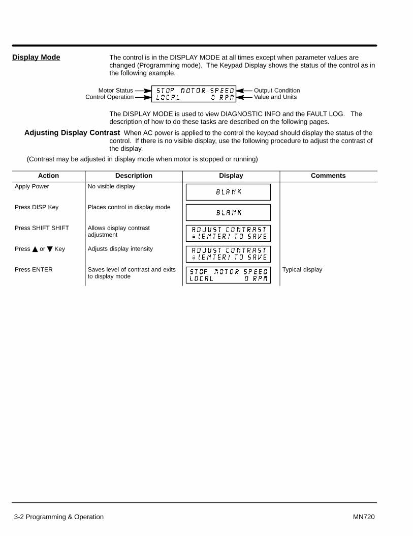
Section 1General Information
3-2 Programming & Operation MN720
Display Mode The control is in the DISPLAY MODE at all times except when parameter values arechanged (Programming mode). The Keypad Display shows the status of the control as inthe following example.
Motor StatusControl Operation
Output ConditionValue and Units
The DISPLAY MODE is used to view DIAGNOSTIC INFO and the FAULT LOG. Thedescription of how to do these tasks are described on the following pages.
Adjusting Display Contrast When AC power is applied to the control the keypad should display the status of thecontrol. If there is no visible display, use the following procedure to adjust the contrast ofthe display.
(Contrast may be adjusted in display mode when motor is stopped or running)
Action Description Display Comments
Apply Power No visible display
Press DISP Key Places control in display mode
Press SHIFT SHIFT Allows display contrastadjustment
Press or Key Adjusts display intensity
Press ENTER Saves level of contrast and exitsto display mode
Typical display
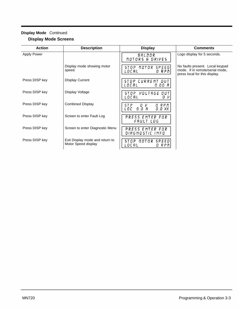
Section 1General Information
Programming & Operation 3-3MN720
Display Mode Continued
Display Mode Screens
Action Description Display Comments
Apply Power Logo display for 5 seconds.
Display mode showing motorspeed.
No faults present. Local keypadmode. If in remote/serial mode,press local for this display.
Press DISP key DIsplay Current
Press DISP key DIsplay Voltage
Press DISP key Combined DIsplay
Press DISP key Screen to enter Fault Log
Press DISP key Screen to enter Diagnostic Menu
Press DISP key Exit Display mode and return toMotor Speed display

Section 1General Information
3-4 Programming & Operation MN720
Display Mode Continued
Display Screens & Diagnostic Information Access
Action Description Display Comments
Apply Power Logo display for 5 seconds.
Display mode showing motorspeed.
No faults present. Local keypadmode. If in remote/serial mode,press local for this display.
Press DISP key 5 times Scroll to Diagnostic Informationscreen
Diagnostic Access screen.
Press ENTER key Access diagnostic information. First Diagnostic Informationscreen.
Press DISP key Display mode showing controltemperature.
Press DISP key Display mode showing %overload current remaining.
Press DISP key Display mode showing optoinputs & outputs states.0=Open, 1=Closed
Opto Inputs states (Left); Opto Outputs states (Right).
Press DISP key Display mode showing actualdrive running time.
HR.MIN.SEC format.
Press DISP key Display mode showing operatingmode, voltage and control type.
Press DISP key Display mode showing continuousamps; PK amps rating; amps/voltscale of feedback, power base ID.
ID is displayed as a hexadecimalvalue.
Press DISP key Display mode showing whichGroup1 or 2 expansion boardsare installed.
Press DISP key Display mode showing motorshaft revolutions from the REVhome set point.
Press DISP key Display mode showing firmwareversion and revision installed inthe control.
Press DISP key Displays exit choice. Press ENTER to exit diagnosticinformation.
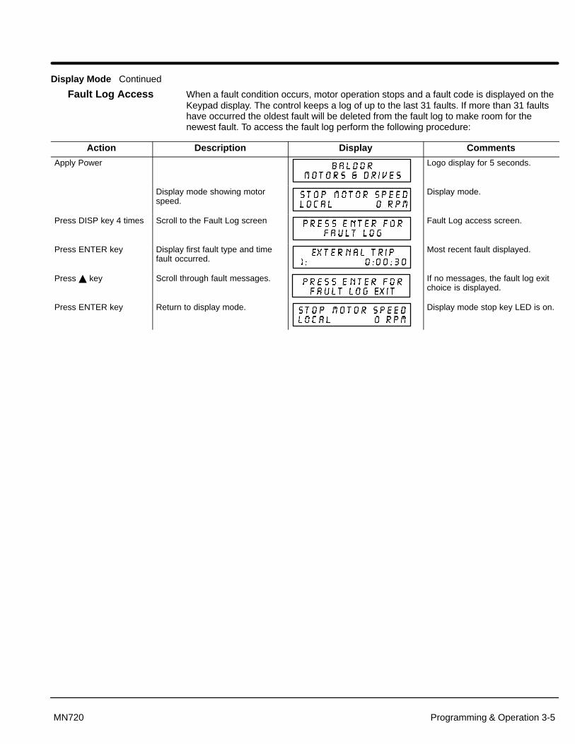
Section 1General Information
Programming & Operation 3-5MN720
Display Mode Continued
Fault Log Access When a fault condition occurs, motor operation stops and a fault code is displayed on theKeypad display. The control keeps a log of up to the last 31 faults. If more than 31 faultshave occurred the oldest fault will be deleted from the fault log to make room for thenewest fault. To access the fault log perform the following procedure:
Action Description Display Comments
Apply Power Logo display for 5 seconds.
Display mode showing motorspeed.
Display mode.
Press DISP key 4 times Scroll to the Fault Log screen Fault Log access screen.
Press ENTER key Display first fault type and timefault occurred.
Most recent fault displayed.
Press key Scroll through fault messages. If no messages, the fault log exitchoice is displayed.
Press ENTER key Return to display mode. Display mode stop key LED is on.
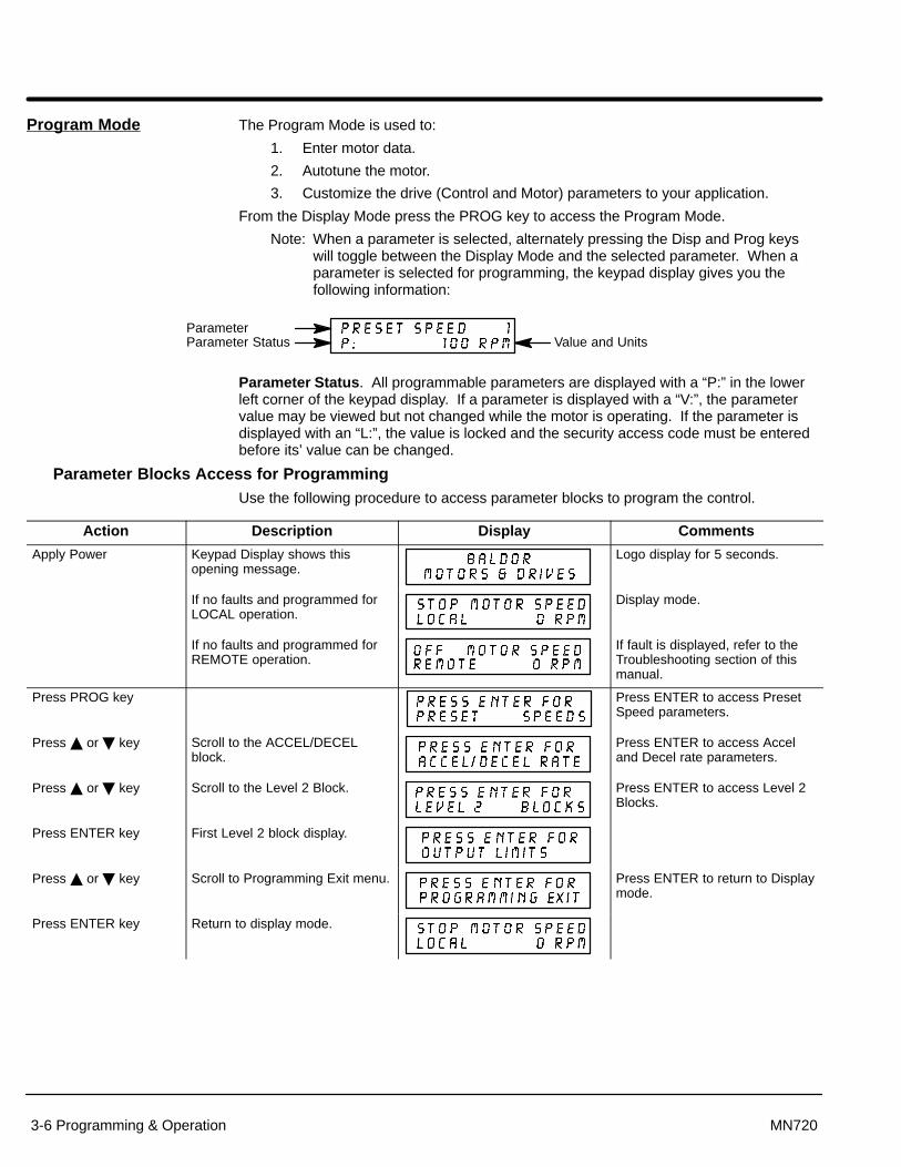
Section 1General Information
3-6 Programming & Operation MN720
Program Mode The Program Mode is used to:
1. Enter motor data.
2. Autotune the motor.
3. Customize the drive (Control and Motor) parameters to your application.
From the Display Mode press the PROG key to access the Program Mode.
Note: When a parameter is selected, alternately pressing the Disp and Prog keyswill toggle between the Display Mode and the selected parameter. When aparameter is selected for programming, the keypad display gives you thefollowing information:
Parameter StatusParameter
Value and Units
Parameter Status. All programmable parameters are displayed with a “P:” in the lowerleft corner of the keypad display. If a parameter is displayed with a “V:”, the parametervalue may be viewed but not changed while the motor is operating. If the parameter isdisplayed with an “L:”, the value is locked and the security access code must be enteredbefore its’ value can be changed.
Parameter Blocks Access for ProgrammingUse the following procedure to access parameter blocks to program the control.
Action Description Display Comments
Apply Power Keypad Display shows thisopening message.
Logo display for 5 seconds.
If no faults and programmed forLOCAL operation.
Display mode.
If no faults and programmed forREMOTE operation.
If fault is displayed, refer to theTroubleshooting section of thismanual.
Press PROG key Press ENTER to access PresetSpeed parameters.
Press or key Scroll to the ACCEL/DECELblock.
Press ENTER to access Acceland Decel rate parameters.
Press or key Scroll to the Level 2 Block. Press ENTER to access Level 2Blocks.
Press ENTER key First Level 2 block display.
Press or key Scroll to Programming Exit menu. Press ENTER to return to Displaymode.
Press ENTER key Return to display mode.
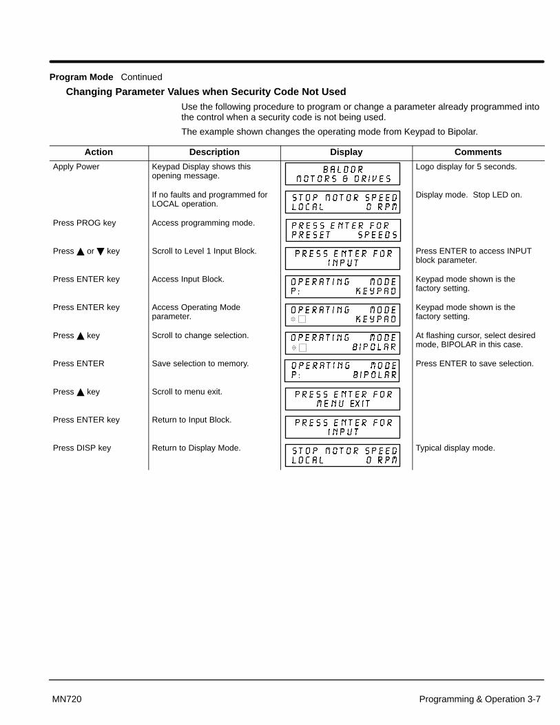
Section 1General Information
Programming & Operation 3-7MN720
Program Mode Continued
Changing Parameter Values when Security Code Not Used Use the following procedure to program or change a parameter already programmed intothe control when a security code is not being used.
The example shown changes the operating mode from Keypad to Bipolar.
Action Description Display Comments
Apply Power Keypad Display shows thisopening message.
Logo display for 5 seconds.
If no faults and programmed forLOCAL operation.
Display mode. Stop LED on.
Press PROG key Access programming mode.
Press or key Scroll to Level 1 Input Block. Press ENTER to access INPUTblock parameter.
Press ENTER key Access Input Block. Keypad mode shown is thefactory setting.
Press ENTER key Access Operating Modeparameter.
Keypad mode shown is thefactory setting.
Press key Scroll to change selection. At flashing cursor, select desiredmode, BIPOLAR in this case.
Press ENTER Save selection to memory. Press ENTER to save selection.
Press key Scroll to menu exit.
Press ENTER key Return to Input Block.
Press DISP key Return to Display Mode. Typical display mode.

Section 1General Information
3-8 Programming & Operation MN720
Program Mode Continued
Reset Parameters to Factory SettingsSometimes it is necessary to restore the parameter values to the factory settings. Followthis procedure to do so. Be sure to change the Level 2 Motor Data block “Motor RatedAmps” to the correct value after this procedure (restored factory setting is 999).
Note: All specific application parameters already programmed will be lost whenresetting the control to factory settings.
Note: After factory settings are restored, the drive must be auto tuned.
Action Description Display Comments
Apply Power Keypad Display shows thisopening message.
Logo display for 5 seconds.
If no faults and programmed forLOCAL operation.
Display mode. Stop LED on.
Press PROG key Enter program mode.
Press or key Scroll to Level 2 Blocks.
Press ENTER key Select Level 2 Blocks.
Press or key Scroll to the Miscellaneous block.
Press ENTER key Select Miscellaneous block.
Press key Scroll to Factory Settingsparameter.
Press ENTER key Access Factory Settingsparameter.
� represents blinking cursor.
Press key Scroll to YES, to choose originalfactory settings.
Press ENTER key Restores factory settings. “Loading Presets” is first message“Operation Done” is next“No” is displayed last.
Press key Scroll to menu exit. Exit Level 2 blocks.
Press or key Scroll to Programming exit. Exit Programming mode andreturn to Display mode.
Press ENTER key Return to display mode. Display mode. Stop LED on.

Section 1General Information
Programming & Operation 3-9MN720
Program Mode Continued
Initialize New FirmwareAfter new firmware is installed, the control must be initialized to the new firmware version and memory locations.Use the following procedure to Initialize the firmware.
Note: All specific application parameters already programmed will be lost when resetting the control to factorysettings.
Note: After factory settings have been restored, the drive must be auto tuned.
Action Description Display CommentsApply Power Keypad Display shows this
opening message.Logo display for 5 seconds.
If no faults and programmed forLOCAL operation.
Display mode. Stop LED on.
Press PROG key Enter program mode.
Press or key Scroll to Level 2 Blocks.
Press ENTER key Select Level 2 Blocks.
Press or key Scroll to the Miscellaneous block.
Press ENTER key Select Miscellaneous block.
Press key Scroll to Factory Settingsparameter.
Press ENTER key Access Factory Settingsparameter.
� represents blinking cursor.
Press key Scroll to YES, to choose originalfactory settings.
Press ENTER key Restores factory settings. “Loading Presets” is first message“Operation Done” is next“No” is displayed last.
Press key Scroll to menu exit.
Press ENTER key Return to display mode. Display mode. Stop LED on.
Press DISP key severaltimes
Scroll to diagnostic informationscreen.
If you wish to verify the firmwareversion, enter diagnostic info.
Press ENTER key Access diagnostic information. Displays commanded speed,direction of rotation, Local/Remote and motor speed.
Press DISP key Display mode showing firmwareversion and revision installed inthe control.
Verify new firmware version.
Press DISP key Displays exit choice. Press ENTER to exit diagnosticinformation.

Section 1General Information
3-10 Programming & Operation MN720
Operating the Control from the KeypadIf the control is configured for remote or serial control, the LOCAL MODE must beactivated before the control may be operated from the keypad. To activate the LOCALMODE, first the motor must be stopped via the keypad, remote or serial commands.When the motor has stopped, the LOCAL MODE is activated by pressing the LOCAL key.Selection of the LOCAL MODE overrides any remote or serial control inputs except forthe External Trip input, J1-16.
Note: If the control has been configured, via parameter settings, for KEYPADMODE, then no other means of operation are permitted other then thekeypad.
From the keypad, the control can operate the motor in three ways; keypad entered speedadjustments, Arrow key speed adjustment, or JOG mode commands.
Keypad entered speed adjustments
Action Description Display CommentsApply Power Keypad Display shows this
opening message.Logo display for 5 seconds.
If no faults and programmed forLOCAL operation.
Display mode. Stop LED on.
Press FWD or REV key Commands forward or reversemotor operation at selectedspeed.
FWD or REV LED on.
Press ENTER key Access speed adjustment. Speed adjustment display.� represents blinking cursor.
Press SHIFT key Move cursor right one digit.
Press key Increase value of 2nd digit.
Press ENTER key Save new value and return toprevious display.
Press FWD or REV key Commands forward or reversemotor operation at selectedspeed.
Press STOP key Commands motor to decelerate. STOP LED is ON when motorreaches 0 RPM.
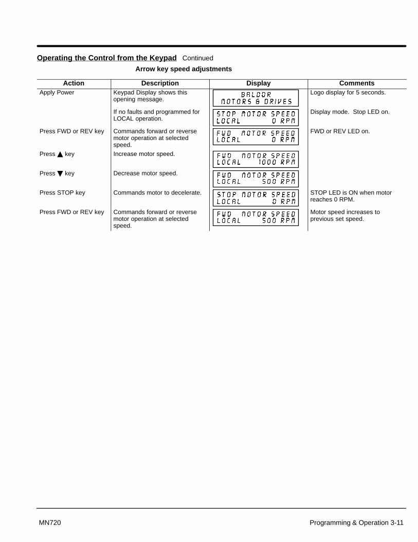
Section 1General Information
Programming & Operation 3-11MN720
Operating the Control from the Keypad Continued
Arrow key speed adjustments
Action Description Display CommentsApply Power Keypad Display shows this
opening message.Logo display for 5 seconds.
If no faults and programmed forLOCAL operation.
Display mode. Stop LED on.
Press FWD or REV key Commands forward or reversemotor operation at selectedspeed.
FWD or REV LED on.
Press key Increase motor speed.
Press key Decrease motor speed.
Press STOP key Commands motor to decelerate. STOP LED is ON when motorreaches 0 RPM.
Press FWD or REV key Commands forward or reversemotor operation at selectedspeed.
Motor speed increases toprevious set speed.

Section 1General Information
3-12 Programming & Operation MN720
Operating the Control from the Keypad Continued
JOG mode commands
Action Description Display CommentsApply Power Keypad Display shows this
opening message.Logo display for 5 seconds.
If no faults and programmed forLOCAL operation.
Display mode. Stop LED is on.
Press JOG key Enable JOG mode (speed is setin the Level 1 Jog Settings block,JOG Speed parameter value).
JOG LED is on.
Press and hold FWD or REV key
Increase motor speed. Motor runs at programmed JOGspeed while FWD or REV key isdepressed. JOG LED is on.
Press STOP key Commands motor to decelerate. STOP LED is ON when motorreaches 0 RPM.

Section 1General Information
Programming & Operation 3-13MN720
Parameter Definitions To make programming easier, parameters have been arranged into the two levelstructure shown in Table 3-1. Press the PROG key to enter the programming mode andthe “Preset Speeds” programming block will be displayed. Use the Up () and Down() arrows to scroll through the parameter blocks. Press ENTER to access parameterswithin a programing block.
Tables 3-2 and 3-3 provide an explanation of each parameter. A complete ParameterBlock Values list is located at the end of this manual. This list defines the programmablerange and factory preset value for each parameter. The list has a space to record yoursettings for future reference.
Table 3-1 List of Parameters
LEVEL 1 BLOCKS LEVEL 2 BLOCKS Preset Speeds Input Output Limits Motor DataPreset Speed #1 Operating Mode Operating Zone Armature VoltagePreset Speed #2 Command Select Min Output Speed ARM Rated AmpsPreset Speed #3 ANA CMD Inverse Max Output Speed Motor Rated SPDPreset Speed #4 ANA CMD Offset PK Current Limit Motor FieldPreset Speed #5 ANA 2 Deadband CUR Rate Limit Motor Field VoltsPreset Speed #6 Motor Field AmpsPreset Speed #7 Output Feedback TypePreset Speed #8 Opto Output #1 Custom Units Encoder CountsPreset Speed #9 Opto Output #2 Decimal Places Resolver SpeedPreset Speed #10 Opto Output #3 Value at Speed Tachometer VoltsPreset Speed #11 Opto Output #4 Units of Measure PK Power LimitPreset Speed #12 Zero SPD Set PTPreset Speed #13 At Speed Band Protection Process ControlPreset Speed #14 Set Speed Overload Process FeedbackPreset Speed #15 Analog Out #1 External Trip Process Inverse
Analog Out #2 Following Error Setpoint SourceAccel / Decel Rate Analog #1 Scale Torque Proving Setpoint CommandAccel Time #1 Analog #2 Scale Set PT ADJ LimitDecel Time #1 Position Band Miscellaneous Process ERR TOLS-Curve #1 Restart Auto/Man Process PROP GainAccel Time #2 DC Control Restart Fault/Hr Process INT GainDecel Time #2 Ctrl Base Volts Restart Delay Process DIFF GainS-Curve #2 Feedback Filter Factory Settings Follow I:O Ratio
Feedback Dir Homing Speed Follow I:O OutJog Settings ARM PROP Gain Homing Offset Master EncoderJog Speed ARM INT GainJog Accel Time Speed PROP Gain Security Control Auto-TuningJog Decel Time Speed INT Gain Security State CALC PresetsJog S-Curve Time Speed DIFF Gain Access Timeout CMD Offset Trim
Position Gain Access Code CUR Loop CompKeypad Setup IR COMP Gain Feedback TestsKeypad Stop Key TACH Trim SPD CNTRLR CALCKeypad Stop Mode Null Force GainKeypad Run FwdKeypad Run Rev Field ControlKeypad Jog Fwd Field PWR SupplyKeypad Jog Rev Field ECON Level
Forcing LevelField Set SpeedField Step LimitField REG Gain
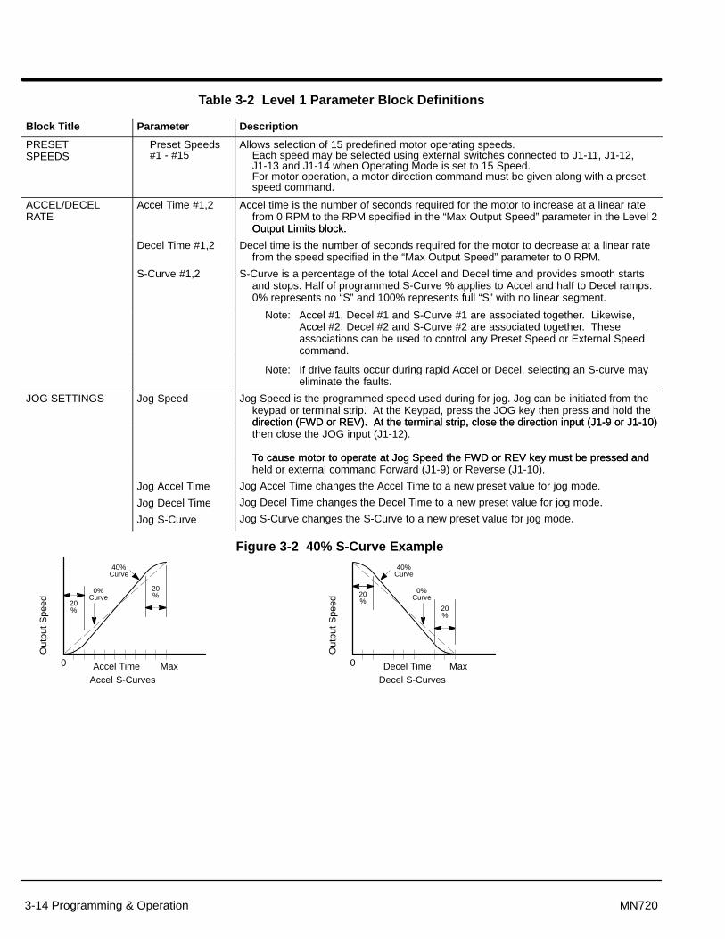
Section 1General Information
3-14 Programming & Operation MN720
Table 3-2 Level 1 Parameter Block Definitions
Block Title Parameter Description
PRESETSPEEDS
Preset Speeds#1 - #15
Allows selection of 15 predefined motor operating speeds. Each speed may be selected using external switches connected to J1-11, J1-12,J1-13 and J1-14 when Operating Mode is set to 15 Speed.For motor operation, a motor direction command must be given along with a presetspeed command.
ACCEL/DECELRATE
Accel Time #1,2 Accel time is the number of seconds required for the motor to increase at a linear ratefrom 0 RPM to the RPM specified in the “Max Output Speed” parameter in the Level 2Output Limits block.
Decel Time #1,2
Output Limits block.
Decel time is the number of seconds required for the motor to decrease at a linear ratefrom the speed specified in the “Max Output Speed” parameter to 0 RPM.
S-Curve #1,2 S-Curve is a percentage of the total Accel and Decel time and provides smooth startsand stops. Half of programmed S-Curve % applies to Accel and half to Decel ramps.0% represents no “S” and 100% represents full “S” with no linear segment.
Note: Accel #1, Decel #1 and S-Curve #1 are associated together. Likewise,Accel #2, Decel #2 and S-Curve #2 are associated together. Theseassociations can be used to control any Preset Speed or External Speedcommand.
Note: If drive faults occur during rapid Accel or Decel, selecting an S-curve mayeliminate the faults.
JOG SETTINGS Jog Speed Jog Speed is the programmed speed used during for jog. Jog can be initiated from thekeypad or terminal strip. At the Keypad, press the JOG key then press and hold thedirection (FWD or REV). At the terminal strip, close the direction input (J1-9 or J1-10)direction (FWD or REV). At the terminal strip, close the direction input (J1-9 or J1-10)then close the JOG input (J1-12).
To cause motor to operate at Jog Speed the FWD or REV key must be pressed and
Jog Accel Time
To cause motor to operate at Jog Speed the FWD or REV key must be pressed andheld or external command Forward (J1-9) or Reverse (J1-10).
Jog Accel Time changes the Accel Time to a new preset value for jog mode.
Jog Decel Time
Jog S-Curve
Jog Decel Time changes the Decel Time to a new preset value for jog mode.
Jog S-Curve changes the S-Curve to a new preset value for jog mode.
Figure 3-2 40% S-Curve Example
Out
put
Spe
ed
Accel Time0 MaxAccel S-Curves
20%
20%
0%Curve
40%Curve
Out
put
Spe
ed
Decel Time0 MaxDecel S-Curves
20%
20%
0%Curve
40%Curve
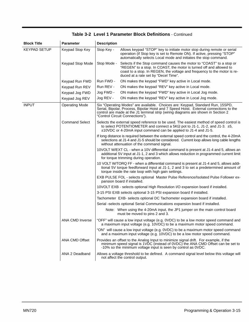
Section 1General Information
Programming & Operation 3-15MN720
Table 3-2 Level 1 Parameter Block Definitions - Continued
Block Title Parameter Description
KEYPAD SETUP Keypad Stop Key
Keypad Stop Mode
Stop Key - Allows keypad “STOP” key to initiate motor stop during remote or serialoperation (if Stop key is set to Remote ON). If active, pressing “STOP”automatically selects Local mode and initiates the stop command.
Stop Mode - Selects if the Stop command causes the motor to “COAST” to a stop or“REGEN” to a stop. In COAST, the motor is turned off and allowed tocoast to a stop. In REGEN, the voltage and frequency to the motor is re-
Keypad Run FWD
Keypad Run REV
Keypad Jog FWD
Keypad Jog REV
duced at a rate set by “Decel Time”.
Run FWD - ON makes the keypad “FWD” key active in Local mode.
Run REV - ON makes the keypad “REV” key active in Local mode.
Jog FWD - ON makes the keypad “FWD” key active in Local Jog mode.
Jog REV - ON makes the keypad “REV” key active in Local Jog mode.
INPUT Operating Mode Six “Operating Modes” are available. Choices are: Keypad, Standard Run, 15SPD,Serial, Bipolar, Process, Bipolar Hoist and 7 Speed Hoist. External connections to thecontrol are made at the J1 terminal strip (wiring diagrams are shown in Section 2“Control Circuit Connections”).
Command Select Selects the external speed reference to be used. The easiest method of speed control isto select POTENTIOMETER and connect a 5K� pot to J1-1, J1-2, and J1-3. ±5,±10VDC or 4-20mA input command can be applied to J1-4 and J1-5.
If long distance is required between the external speed control and the control, the 4-20mAselections at J1-4 and J1-5 should be considered. Current loop allows long cable lengthswithout attenuation of the command signal.
10VOLT W/EXT CL - when a 10V differential command is present at J1-4 and 5, allows anadditional 5V input at J1-1, 2 and 3 which allows reduction in programmed current limitfor torque trimming during operation.
10 VOLT W/TORQ FF - when a differential command is present at J1-4 and 5, allows addi-tional 5V torque feedforward input at J1-1, 2 and 3 to set a predetermined amount oftorque inside the rate loop with high gain settings.
EXB PULSE FOL - selects optional Master Pulse Reference/Isolated Pulse Follower ex-pansion board if installed.
10VOLT EXB - selects optional High Resolution I/O expansion board if installed.
3-15 PSI EXB selects optional 3-15 PSI expansion board if installed.
Tachometer EXB- selects optional DC Tachometer expansion board if installed.
Serial -selects optional Serial Communications expansion board if installed.
Note: When using the 4-20mA input, the JP1 jumper on the main control boardmust be moved to pins 2 and 3.
ANA CMD Inverse “OFF” will cause a low input voltage (e.g. 0VDC) to be a low motor speed command anda maximum input voltage (e.g. 10VDC) to be a maximum motor speed command.
“ON” will cause a low input voltage (e.g. 0VDC) to be a maximum motor speed commandand a maximum input voltage (e.g. 10VDC) to be a low motor speed command.
ANA CMD Offset Provides an offset to the Analog Input to minimize signal drift. For example, if theminimum speed signal is 1VDC (instead of 0VDC) the ANA CMD Offset can be set to-10% so the minimum voltage input is seen by control as 0VDC.
ANA 2 Deadband Allows a voltage threshold to be defined. A command signal level below this voltage willnot affect the control output.

Section 1General Information
3-16 Programming & Operation MN720
Table 3-2 Level 1 Parameter Block Definitions - Continued
Block Title Parameter Description
OUTPUT OPTO OUTPUT #1 - #4
Four optically isolated digital outputs that have two operating states, logical High or Low.Each output may be configured to any of the following conditions:
Condition Description
Ready - Active when power is applied and no faults are present.
Zero Speed - Active when output frequency to motor is below the value of theLevel 1 Output “Zero SPD Set Pt” parameter.
At Speed - Active when output speed is within the speed range defined bythe Level 1 Output “At Speed Band” parameter.
At Set Speed - Active when output speed is at or above the Level 1 Output “Set Speed” parameter.
Overload - A normally closed contact that is active (opens) during anOverload fault caused by a time out when output current isgreater than Rated Current.
Keypad Control - Active when control is in Local keypad control.
Fault - Active when a fault condition is present.
Following ERR - Active when the motor speed is outside the user specifiedtolerance band defined by the At Speed Band parameter.
Motor Direction - Active High when REV direction command received. Active Lowwhen FWD direction command received.
Drive On - Active when control is Enabled and “Ready”.
CMD Direction - Active at all times. Logical output state indicates Forward(Open) or Reverse (Closed) direction.
AT Position - Active during a positioning command when control is within theposition band parameter tolerance.
Over Temp Warn - Active when control heat sink is within 3°C of Int Overtemp.
Process Error - Active when process feedback signal is outside the rangespecified by the Level 2 Process Control block, AT SetpointBand parameter. Turns off when process feedback error iseliminated.
Drive Run - Active when drive is Ready, Enabled, Speed or Torque commandreceived with FWD/REV direction issued.
Running Field - Active when field current is greater than 90% of the userprogrammed motor field amps. Could be used as a torque readyoutput.
M/FWD Contact - May be used to close an external motor armature contactor. Thisoutput is high when the control is ready and a forward or reversecommand is issued. There is a 16ms delay between M/FWDCONTACT ON and when the control actually engages the outputbridge. The delay helps compensate for any contactor bounce.The output turns OFF when forward and reverse are droppedand after the armature current is reduced to zero. Refer to OptoOutput description of Section 2.

Section 1General Information
Programming & Operation 3-17MN720
Table 3-2 Level 1 Parameter Block Definitions - Continued
Block Title Parameter Description
OUTPUT(Continued)
Zero SPD Set PT Sets the speed at which the Zero Speed opto output becomes active (turns on). When thespeed is less than the ZERO SPD SET PT, the Opto Output becomes active. This is use-ful when a motor brake is to interlock operation with a motor.
At Speed Band The At Speed Band serves two Opto Output Conditions and the Level 2 Protection blockFollowing Error:
Sets the speed range in RPM at which the At Speed opto output turns on and remainsactive within the range.
Sets the Following Error Tolerance Band for the Level 1 OUTPUT, Opto Output conditionFollowing ERR. The opto output is active if the motor speed is outside this band.
Sets the no fault operating speed range of the drive. This value is used by the Level 2Protection block, Following Error parameter (if it is set to ON). If the drive speed fallsout of this band, the Level 2 Protection block, Following Error parameter will shutdown the drive (if it is set to ON).
Set Speed Sets the speed that the AT Set Speed opto output becomes active (turns on). When thespeed is greater than the Level 1 Output SET SPEED parameter, the Opto Outputbecomes active. This is useful when another machine must not start or stop until themotor exceeds a predetermined speed.
Analog Output #1 and #2
Two Analog 0-5VDC linear outputs may be configured to represent any of 19 conditionsas follows:
Condition Description
ABS Speed - Represents the absolute motor speed where 0VDC = 0 RPM and+5VDC = MAX RPM.
ABS Torque - Represents the absolute value of torque where +5VDC = Torque atCURRENT LIMIT. The absolute torque output is scaled by thetorque constant. The torque constant or torque per armature ampdrops as the field current drops. Thus, in field weakening the torqueoutput remains accurate. Useful as a load meter output.
ABS Speed - Represents the absolute value of commanded speed Command where +5VDC = MAX RPM.
Field Current - 5 VDC = max. supply amps (e.g. 5V = 15 amps for a 15 amp fieldpower supply).
CMD Field CUR - 5 VDC = max supply amps.
ARM Current - 2.5 VDC = 0.0, +5 VDC = + current limit, 0 VDC = - current limit.
CMD ARM CUR - 2.5 VDC = 0.0, +5 VDC = + current limit, 0 VDC = - current limit.
Firing Angle - Firing angle scaled +2.5 V = 0. 0V = max regen. +5V = MAX ADVANCE.
ARM Volts - Arm volts scaled 2.5V = 0, 0V =
Field Volts - Field volts, 4 volts = RATED FIELD VOLTAGE.
Torque - Bipolar torque output. 2.5V centered, 5V = Max Positive Torque, 0V = Max negative torque.
Power - Bipolar power output. 2.5V = Zero Power, 0V = negative rated peakpower, +5V = Positive rated peak power.
Velocity - Represents motor speed scaled to 0V = negative max RPM, +2.5V = Zero Speed, +5V = positive max RPM.
Overload - (Accumulated current)2 x (time), Overload occurs at +5V. (I2t)
Position - Position within a single revolution. +5V = 1 complete revolution. The counter will reset to 0 every revolution.
Line Timer - Internally used square wave form, phase locked to L1-L2.
Analog Scale #1 
Scale factor for the Analog Output voltage. Useful to set the zero value or full scalerange for external meters.
Position Band Sets the acceptable range in digital counts (pulses) at which the AT Position Optobecomes active (turns on).
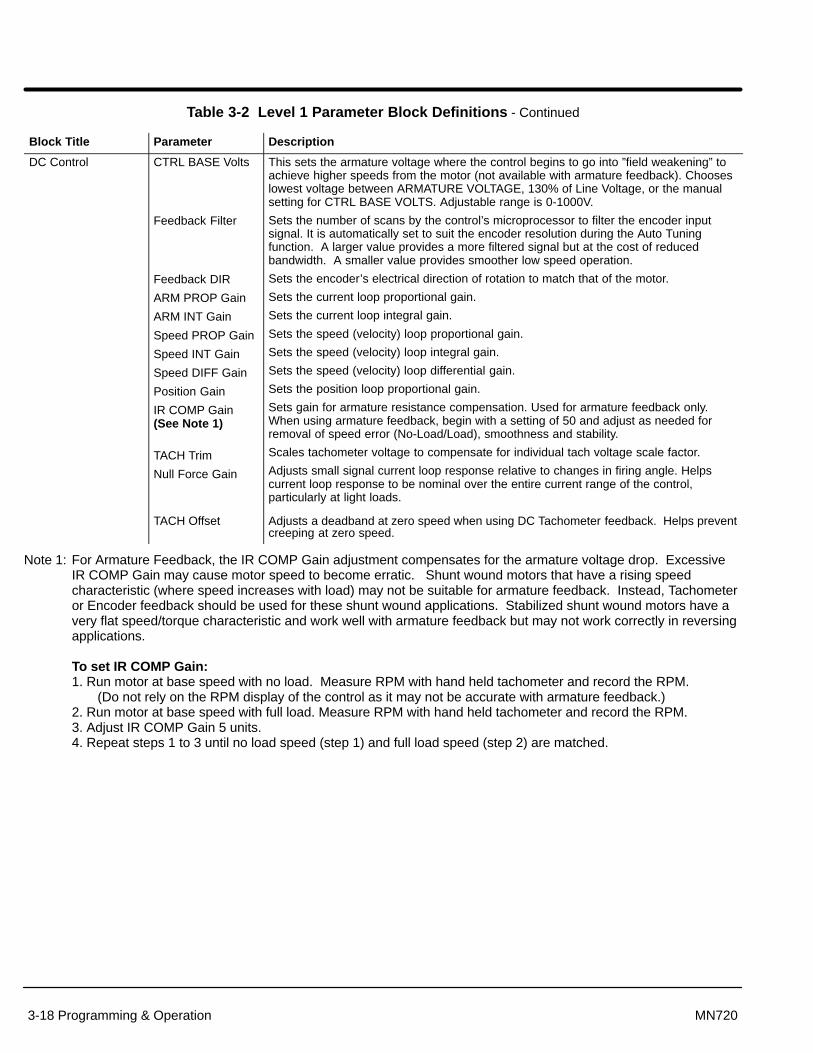
Section 1General Information
3-18 Programming & Operation MN720
Table 3-2 Level 1 Parameter Block Definitions - Continued
Block Title Parameter Description
DC Control CTRL BASE Volts
Feedback Filter
Feedback DIR
ARM PROP Gain
ARM INT Gain
Speed PROP Gain
Speed INT Gain
Speed DIFF Gain
Position Gain
IR COMP Gain(See Note 1)
TACH Trim
Null Force Gain
This sets the armature voltage where the control begins to go into ”field weakening” toachieve higher speeds from the motor (not available with armature feedback). Chooseslowest voltage between ARMATURE VOLTAGE, 130% of Line Voltage, or the manualsetting for CTRL BASE VOLTS. Adjustable range is 0-1000V.
Sets the number of scans by the control’s microprocessor to filter the encoder inputsignal. It is automatically set to suit the encoder resolution during the Auto Tuningfunction. A larger value provides a more filtered signal but at the cost of reducedbandwidth. A smaller value provides smoother low speed operation.
Sets the encoder’s electrical direction of rotation to match that of the motor.
Sets the current loop proportional gain.
Sets the current loop integral gain.
Sets the speed (velocity) loop proportional gain.
Sets the speed (velocity) loop integral gain.
Sets the speed (velocity) loop differential gain.
Sets the position loop proportional gain.
Sets gain for armature resistance compensation. Used for armature feedback only.When using armature feedback, begin with a setting of 50 and adjust as needed forremoval of speed error (No-Load/Load), smoothness and stability.
Scales tachometer voltage to compensate for individual tach voltage scale factor.
Adjusts small signal current loop response relative to changes in firing angle. Helpscurrent loop response to be nominal over the entire current range of the control,particularly at light loads.
TACH Offset Adjusts a deadband at zero speed when using DC Tachometer feedback. Helps preventcreeping at zero speed.
Note 1: For Armature Feedback, the IR COMP Gain adjustment compensates for the armature voltage drop. ExcessiveIR COMP Gain may cause motor speed to become erratic. Shunt wound motors that have a rising speedcharacteristic (where speed increases with load) may not be suitable for armature feedback. Instead, Tachometeror Encoder feedback should be used for these shunt wound applications. Stabilized shunt wound motors have avery flat speed/torque characteristic and work well with armature feedback but may not work correctly in reversingapplications.
To set IR COMP Gain:1. Run motor at base speed with no load. Measure RPM with hand held tachometer and record the RPM. (Do not rely on the RPM display of the control as it may not be accurate with armature feedback.)2. Run motor at base speed with full load. Measure RPM with hand held tachometer and record the RPM. 3. Adjust IR COMP Gain 5 units. 4. Repeat steps 1 to 3 until no load speed (step 1) and full load speed (step 2) are matched.

Section 1General Information
Programming & Operation 3-19MN720
Table 3-2 Level 1 Parameter Block Definitions - Continued
Block Title Parameter Description
Field Control Field PWR Supply This is used to select the type of field power supply used with the control. The standardpower supply (for controls to 300HP) can supply up to 15 amps for shunt wound motors.If using permanent magnet motors, the field power supply may be disabled by selectingNONE. If the shunt wound motor requires more than 15 amps for its field, an optional 40amp field power supply may be added.
Field ECON Level Sets the field voltage applied to the motor during stand-still while the control is disabled.This is used to keep the fields warm to ensure the motor can run to its base speed. Fieldeconomy is also often used instead of a space heater. Excessive voltage may cause thefield to overheat resulting in premature motor failure. Any value less than 25% (or 100mA) causes the field economy circuit to be off when disabled and automatically set to0%.
Forcing Level This setting is often used in the hoist mode to over saturate the fields causing a soft startor stop. Only available in Series 20H Line Regen controls and used in BIPOLAR HOISTand 7 SPEED HOIST modes.
Field Set Speed This sets the speed at which the field voltage is switched from the Forcing Level to thestandard field run voltage. Only available in Series 20H Line Regen controls.
Field Step Limit This sets the ramp rate time when changing from field levels (field force voltage tostandard run voltage). Only available in Series 20H Line Regen controls.
Field REG Gain This sets the proportional gain in the field current control.
Field Integral Selects the gain type for the field regulator. Setting Field Integral to ON selects PI gains.OFF selects proportional only. In most cases, the ON setting will improve the accuracyof the field control current settings.
LEVEL 2 BLOCK ENTERS LEVEL 2 MENU
Figure 3-3 Relationship of Field Control Parameters
Field Set Speed
Motor Speed
Drive EnabledField Enable Asserted Drive Disabled
Field Current
Force
Run
Stand (ECON)
Field Decels at 0 second rate
Field Accels at 0 second rate
Field Set SpeedReached
Field Step Limit(Field Steps Follow This Rate)
Field Forcing, Field Set Speed and Field Step Limit parameters are not active with Series20H controls. These parameters are only active for Series 20H Line Regen controlswhen operated in the Bipolar Hoist or 7 Speed Hoist modes.
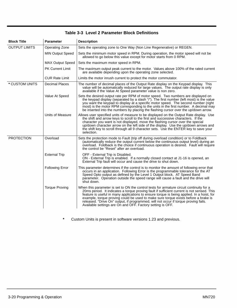
Section 1General Information
3-20 Programming & Operation MN720
Table 3-3 Level 2 Parameter Block Definitions
Block Title Parameter Description
OUTPUT LIMITS Operating Zone Sets the operating zone to One Way (Non Line Regenerative) or REGEN.
MIN Output Speed Sets the minimum motor speed in RPM. During operation, the motor speed will not beallowed to go below this value except for motor starts from 0 RPM.
MAX Output Speed Sets the maximum motor speed in RPM.
PK Current Limit The maximum output peak current to the motor. Values above 100% of the rated currentare available depending upon the operating zone selected.
CUR Rate Limit Limits the motor inrush current to protect the motor commutator.
* CUSTOM UNITS Decimal Places
Value At Speed
Units of Measure
The number of decimal places of the Output Rate display on the Keypad display. Thisvalue will be automatically reduced for large values. The output rate display is onlyavailable if the Value At Speed parameter value is non zero.
Sets the desired output rate per RPM of motor speed. Two numbers are displayed onthe keypad display (separated by a slash “/”). The first number (left most) is the valueyou want the keypad to display at a specific motor speed. The second number (rightmost) is the motor RPM corresponding to the units in the first number. A decimal maybe inserted into the numbers by placing the flashing cursor over the up/down arrow.
Allows user specified units of measure to be displayed on the Output Rate display. Usethe shift and arrow keys to scroll to the first and successive characters. If thecharacter you want is not displayed, move the flashing cursor over the specialup/down character arrow on the left side of the display. Use the up/down arrows andthe shift key to scroll through all 9 character sets. Use the ENTER key to save yourselection.
PROTECTION Overload Sets the protection mode to Fault (trip off during overload condition) or to Foldback(automatically reduce the output current below the continuous output level) during anoverload. Foldback is the choice if continuous operation is desired. Fault will requirethe control be “Reset” after an overload.
External Trip OFF - External Trip is Disabled.ON - External Trip is enabled. If a normally closed contact at J1-16 is opened, anExternal Trip fault will occur and cause the drive to shut down.
Following Error This parameter determines if the control is to monitor the amount of following error thatoccurs in an application. Following Error is the programmable tolerance for the ATSpeed Opto output as defined by the Level 1 Output block, AT Speed Bandparameter. Operation outside the speed range will cause a fault and the drive willshut down.
Torque Proving When this parameter is set to ON the control tests for armature circuit continuity for a20ms period. It indicates a torque proving fault if sufficient current is not sensed. Thisfeature is useful in many applications to ensure torque is being applied. In a hoist, forexample, torque proving could be used to make sure torque exists before a brake isreleased. “Drive On” output, if programmed, will not occur if torque proving fails.Available settings are On and OFF. Factory setting is OFF.
* Custom Units is present in software versions 1.23 and previous.

Section 1General Information
Programming & Operation 3-21MN720
Table 3-3 Level 2 Parameter Block Definitions Continued
Block Title Parameter Description
MISCELLANEOUS Restart Auto/Man Manual - If a fault or power loss occurs, the control must be manually reset to resumeoperation.Automatic - If a fault or power loss occurs, the control will automatically reset toresume operation.
Restart Fault/Hr The maximum number of automatic restart attempts before requiring a manual restart.After one hour without reaching the maximum number of faults or if power is turnedoff and on again, the fault count is reset to zero.
Restart Delay The amount of time allowed after a fault condition for an automatic restart to occur.Useful to allow sufficient time to clear a fault before restart is attempted.
Factory Settings Restores factory settings for all parameter values. Select YES and press “ENTER” keyto restore factory parameter values. The keypad Display will show “Operation Done”then return to “NO” when completed.
Note: When factory settings are reset, the Motor Rated Amps value is reset to999.9 amps. This Level 2 Motor Data block parameter value must bechanged to the correct value (located on the motor rating plate) beforeattempting to start the drive and auto tune.
Homing Speed In Bipolar and Serial modes, this parameter sets the speed that the motor shaft willrotate to a “Home” position when the orient input switch is closed (J1-11).
Homing Offset In Bipolar and Serial modes, this parameter sets the number of digital encoder countspast home at which the motor stop command is issued. Quadrature encoder pulsesare 4 times the number of encoder lines per revolution. The recommended minimumnumber is 100 encoder counts to allow for deceleration distance to allow the motor tostop smoothly.
Note: Homing direction is always forward.

Section 1General Information
3-22 Programming & Operation MN720
Table 3-3 Level 2 Parameter Block Definitions Continued
Block Title Parameter Description
SECURITYCONTROL
Security State Off - No security Access Code required to change parameter values.Local - Requires security Access Code to be entered before changes can be madeusing the Keypad.Serial - Requires security Access Code to be entered before changes can be madeusing the Serial Link.Total - Requires security Access Code to be entered before changes can be madeusing the Keypad or serial link.
Note: If security is set to Local, Serial or Total you can press PROG and scrollthrough the parameter values that are programmed but you are not allowedto change them unless you enter the correct access code.
Access Timeout The time in seconds the security access remains enabled after leaving the programmingmode. If you exit and go back into the program Mode within this time limit, thesecurity Access Code does not have to be re-entered. This timer starts when leavingthe Program Mode (by pressing DISP).
Access Code A 4 digit number code. Only persons that know the code can change secured Level 1and Level 2 parameter values.
Note: Please record your access code and store it in a safe place. If you cannotgain entry into parameter values to change a protected parameter, pleasecontact Baldor. Be prepared to give the 5 digit code shown on the lowerright side of the Keypad Display at the Security Control Access Codeparameter prompt.
MOTOR DATA Armature Voltage The rated Armature voltage of the motor (listed on the motor nameplate).
ARM Rated Amps The rated armature current of the motor (listed on the motor nameplate). If the motorcurrent exceeds this value for a period of time, an Overload fault will occur.
Motor Rated SPD The rated speed of the motor (listed on the motor nameplate). In the case of wound fieldmotor nameplates, speed may be indicated as Base Speed/Max Field WeakenedSpeed. The base speed is entered in the MOTOR RATED SPD parameter. The MaxField Weakened Speed may be entered in the MAXIMUM OUTPUT SPEEDparameter located in the Output Limits block, if operation faster than base speed isdesired.
Motor Field This indicates the type of field in the motor. Available settings are Shunt and PermanentMagnet.
Motor Field Volts The rated field volts of the motor (listed on the motor nameplate based on theconnections you have made). Many motors have a dual voltage field that may beconnected in series or parallel. Maximum field voltage = (AC Line Volts) x 0.85.
Motor Field Amps The rated field amps of the motor for base speed operation and based on theconnections you have made. Many motors have a dual voltage field. This is stated onthe motor nameplate or shown in the motor connection diagram. The standard fieldsupply for controls up to 300HP is 15 Amps. An optional 40 Amp field supply isavailable for dual voltage field motors and for controls that are 400HP and larger.If the field current drops to less than 0.15A, a Field Loss Fault will be displayed by thecontrol.
Feedback Type This designates the type of feedback used by the control. The control’s standardfeedback options are ENCODER and ARMATURE. Specify ARMATURE if the controlis operated open loop and start with the IR Comp Gain set to 50. DC tachometer andresolver feedback are available with the appropriate optional expansion boards.Feedback device must be coupled to the motor shaft or at a 1:1 ratio.
Encoder Counts The number of counts (pulses) per revolution, if an encoder is feedback type.
Resolver Speed The speed of the resolver, if a resolver is used for feedback type. The parameter is onlyactive when the optional Resolver to Digital expansion board is installed.
Tachometer Volts The DC volts per 1000 RPM output of the tachometer (V/KRPM). The parameter is onlyactive when the optional tachometer feedback expansion board is installed.
PK Power Limit This setting is often used as a commutation limiter in permanent magnet servo motors toset the peak current for commutation limits. This parameter is only active when PERMMAGNET is selected for motor field type.
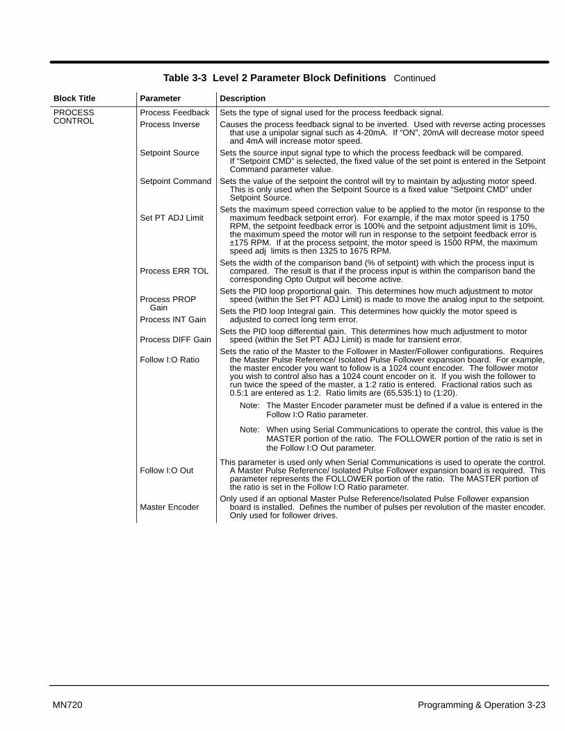
Section 1General Information
Programming & Operation 3-23MN720
Table 3-3 Level 2 Parameter Block Definitions Continued
Block Title Parameter Description
PROCESSCONTROL
Process FeedbackProcess Inverse
Setpoint Source
Setpoint Command
Set PT ADJ Limit
Process ERR TOL
Process PROPGain
Process INT Gain
Process DIFF Gain
Follow I:O Ratio
Follow I:O Out
Master Encoder
Sets the type of signal used for the process feedback signal.Causes the process feedback signal to be inverted. Used with reverse acting processes
that use a unipolar signal such as 4-20mA. If “ON”, 20mA will decrease motor speedand 4mA will increase motor speed.
Sets the source input signal type to which the process feedback will be compared. If “Setpoint CMD” is selected, the fixed value of the set point is entered in the SetpointCommand parameter value.
Sets the value of the setpoint the control will try to maintain by adjusting motor speed.This is only used when the Setpoint Source is a fixed value “Setpoint CMD” underSetpoint Source.
Sets the maximum speed correction value to be applied to the motor (in response to themaximum feedback setpoint error). For example, if the max motor speed is 1750RPM, the setpoint feedback error is 100% and the setpoint adjustment limit is 10%,the maximum speed the motor will run in response to the setpoint feedback error is±175 RPM. If at the process setpoint, the motor speed is 1500 RPM, the maximumspeed adj limits is then 1325 to 1675 RPM.
Sets the width of the comparison band (% of setpoint) with which the process input iscompared. The result is that if the process input is within the comparison band thecorresponding Opto Output will become active.
Sets the PID loop proportional gain. This determines how much adjustment to motorspeed (within the Set PT ADJ Limit) is made to move the analog input to the setpoint.
Sets the PID loop Integral gain. This determines how quickly the motor speed isadjusted to correct long term error.
Sets the PID loop differential gain. This determines how much adjustment to motorspeed (within the Set PT ADJ Limit) is made for transient error.
Sets the ratio of the Master to the Follower in Master/Follower configurations. Requiresthe Master Pulse Reference/ Isolated Pulse Follower expansion board. For example,the master encoder you want to follow is a 1024 count encoder. The follower motoryou wish to control also has a 1024 count encoder on it. If you wish the follower torun twice the speed of the master, a 1:2 ratio is entered. Fractional ratios such as0.5:1 are entered as 1:2. Ratio limits are (65,535:1) to (1:20).
Note: The Master Encoder parameter must be defined if a value is entered in theFollow I:O Ratio parameter.
Note: When using Serial Communications to operate the control, this value is theMASTER portion of the ratio. The FOLLOWER portion of the ratio is set inthe Follow I:O Out parameter.
This parameter is used only when Serial Communications is used to operate the control.A Master Pulse Reference/ Isolated Pulse Follower expansion board is required. Thisparameter represents the FOLLOWER portion of the ratio. The MASTER portion ofthe ratio is set in the Follow I:O Ratio parameter.
Only used if an optional Master Pulse Reference/Isolated Pulse Follower expansionboard is installed. Defines the number of pulses per revolution of the master encoder.Only used for follower drives.

Section 1General Information
3-24 Programming & Operation MN720
Table 3-3 Level 2 Parameter Block Definitions Continued
Block Title Parameter Description
AUTO TUNING
CALC Presets
CMD Offset TrimCUR Loop COMPFeedback Tests
SPD CNTRLRCALC
The Auto Tune procedure is used to automatically measure and calculate certainparameter values after motor data has been entered. Run CALC PRESETS, CMDOFFSET TRIM, CUR LOOP COMP and FEEDBACK TESTS with the motoruncoupled from the load. SPD CNTRLR CALC should be run with the load coupled tothe motor (if possible). Ensure that both the load and motor are free to rotate freely.
This procedure loads preset values into memory that are required to perform Auto Tune.Always run CALC Presets as the first step of Auto Tune.
This procedure trims out voltage offsets for the differential analog input at J1-4 and J1-5.Measures current response to pulses of 30° firing angle.This procedure checks the values for ENCODER COUNTS and ENCODER DIR.
This is accomplished by accelerating the motor open loop, detecting the phasing ofencoder feedback and counting the number of encoder pulses per revolution of themotor. This works for resolvers and determines direction in tachometer systems. Not required for ARMATURE FEEDBACK.
This procedure accelerates the motor to measure the current to acceleration ratio. It also adjusts Speed Control Integral Gain and Speed Control Proportional Gain.Because auto-tune is usually done with no load, it will generally set the Speed ControlIntegral Gain too high for low inertia motors and loads if Current Limit is set too low. Ifthe control is too responsive when loaded, set the current limit to the proper value andrerun this procedure.
LEVEL 1 BLOCK ENTERS LEVEL 1 MENU

Section 4Troubleshooting
Troubleshooting 4-1MN720
The Baldor Series 20H Control requires very little maintenance and should provide yearsof trouble free operation when installed and applied correctly. Occasional visualinspection should be considered to ensure tight wiring connections and to avoid the buildup of any dust, dirt, or foreign debris which can reduce heat dissipation.
Before attempting to service this equipment, all input power must be removed from thecontrol to avoid the possibility of electrical shock. The servicing of this equipment shouldbe handled by a qualified electrical service technician experienced in the area of highpower electronics.
It is important to familiarize yourself with the following information before attempting anytroubleshooting or service of the control. Most troubleshooting can be performed usingonly a digital voltmeter having an input impedance exceeding 1 meg Ohm. In somecases, an oscilloscope with 5 MHZ minimum bandwidth may be useful. Before consultingthe factory, check that all power and control wiring is correct and installed per therecommendations given in this manual.
No Keypad Display - Display Contrast Adjustment If there is no visible display, use the following procedure to adjust the contrast of thedisplay.
Action Description Display Comments
Apply Power No visible display.
Press DISP key Ensures control in Display mode. Display mode.
Press SHIFT key 2 times Allows display contrastadjustment.
Press or key Adjusts display contrast(intensity).
Press ENTER key Saves display contrastadjustment level and exits todisplay mode.

Section 1General Information
4-2 Troubleshooting MN720
How to Access the Fault Log When a fault condition occurs, motor operation stops and a fault code is displayed onthe Keypad display. The control keeps a log of up to the last 31 faults. If more than 31faults have occurred the oldest fault will be deleted from the fault log to make room for thenewest fault. To access the fault log use the following procedure:
Action Description Display Comments
Apply Power Logo display for 5 seconds.
Display mode showing outputfrequency
Display mode.
Press DISP key 5 times Use DISP key to scroll to theFault Log entry point.
Press ENTER key Display first fault type and timefault occurred.
Typical display.
Press key Scroll through fault messages. If no messages, the fault log exitchoice is displayed.
Press ENTER key Return to display mode. Display mode stop key LED is on.
How to Clear the Fault Log Use the following procedure to clear the fault log.
Action Description Display Comments
Apply Power Logo display for 5 seconds.
Display mode showing outputfrequency.
Display mode.
Press DISP key Press DISP to scroll to the FaultLog entry point.
Press ENTER key Displays most recent message.
Press SHIFT key
Press RESET key
Press SHIFT key
Press ENTER key Fault log is cleared. No faults in fault log.
Press or key Scroll Fault Log Exit.
Press ENTER key Return to display mode.

Section 1General Information
Troubleshooting 4-3MN720
How to Access Diagnostic Information
Action Description Display Comments
Apply Power Logo display for 5 seconds.
Display mode showing motorspeed.
No faults present. Local keypadmode. If in remote/serial mode,press local for this display.
Press DISP key 5 times Scroll to Diagnostic Informationscreen
Diagnostic Access screen.
Press ENTER key Access diagnostic information. First Diagnostic Informationscreen.
Press DISP key Display mode showing controltemperature.
Press DISP key Display mode showing %overload current remaining.
Press DISP key Display mode showing optoinputs & outputs states.0=Open, 1=Closed
Opto Inputs states (Left); Opto Outputs states (Right).
Press DISP key Display mode showing actualdrive running time.
HR.MIN.SEC format.
Press DISP key Display mode showing operatingmode, voltage and control type.
Press DISP key Display mode showing continuousamps; PK amps rating; amps/voltscale of feedback, power base ID.
ID is displayed as a hexadecimalvalue.
Press DISP key Display mode showing whichGroup1 or 2 expansion boardsare installed.
Press DISP key Display mode showing motorshaft revolutions from the REVhome set point.
Press DISP key Display mode showing firmwareversion and revision installed inthe control.
Press DISP key Displays exit choice. Press ENTER to exit diagnosticinformation.

Section 1General Information
4-4 Troubleshooting MN720
Table 4-4 Troubleshooting
INDICATION POSSIBLE CAUSE CORRECTIVE ACTION
ARM V FDBK The control has detected anexcessive amount of armaturefeedback voltage on the armatureduring power–up.
The permanent magnet motor may be rotating on power–up.
Excessive noise on cables. Separate armature leads from any other power.
Defective base ID board. Call Baldor if problem remains.
AUTO TUNE Encoder miswired. Correct wiring problems.ENCODER TEST
Encoder coupling slipping, brokenor misaligned.
Correct encoder to motor coupling.
Excessive noise on encoder lines. Check the position counter in the Diagnostic Information for jittering which will confirm an encoder problem.
Use recommended encoder cable.Check encoder connections including shields.Separate encoder leads from power wiring.Cross encoder cables and power leads at 90°.Electrically isolate encoder from motor.Install optional Isolated Encoder Feedback expansion board.
CHK TACHJUMPERS
Incorrect DC tach expansion boardjumper settings.
User entered TACH VOLTS or MAX SPEED has changed the tach boardjumper setting. Check tach board info in the DIAGNOSTICS DISPLAY,correct jumper settings. press RESET.
CURR SENSE Excessive armature currentfeedback.
Suspect ±15V supply fault, wiring between base ID and feedback boards,defective feedback board or TACH board scaling.
ENCODER LOSS Encoder power supply failure. Check 5VDC at J1-29 and J1-30. Also check at encoder end pins D and F.
Encoder coupling slipping, brokenor misaligned
Correct or replace encoder to motor coupling.
Excessive noise on encoder lines. Check the position counter in the Diagnostic Information for jittering which will confirm an encoder problem.
Check encoder connections.Separate encoder leads from power wiring.Cross encoder cables and power leads at 90°.Electrically isolate encoder from motor.Install optional Isolated Encoder Feedback expansion board.
TACH LOSS Tach coupling slipped or broken. Check tach to motor coupling.
Excessive noise on tach lines. Check tach connections. Separate tach leads from power wiring. Cross power leads at 90°. Use shielded tach leads.
Wrong jumper settings on DC TACHexpansion board.
Check jumper selection based on tach output and MAX SPEED of motor.Reset at needed.
DC Contactor may be open. Check contactor.
RESOLVER LOSS Resolver coupling slipped orbroken.
Check resolver to motor coupling.
Incorrect connections to ResolverFeedback expansion board.
Check Resolver Feedback expansion board manual for correct wiringand parameters.
Excessive noise on resolver lines. Check resolver connections. Separate resolver leads from power wiring.Cross power leads at 90°. Use shielded resolver leads.

Section 1General Information
Troubleshooting 4-5MN720
Table 4-4 Troubleshooting Continued
INDICATION POSSIBLE CAUSE CORRECTIVE ACTION
EXTERNAL TRIP Motor ventilation insufficient. Clean motor air intake and exhaust.Check external blower for operation and proper direction of rotation.Verify motor’s internal fan is coupled securely.
Motor draws excessive current. Check motor for overloading. Verify proper sizing of control and motor.
No thermostat connected. Verify thermostat has normally closed contacts. Connect thermostat.Verify connection of all external trip circuits used with thermostat.Disable thermostat input at J1-16 (External Trip Input).
Poor thermostat connections. Check thermostat connections.
External trip parameter incorrect. Verify connection of external trip circuit at J1-16.
Set external trip parameter to “OFF” if no connection made at J1-16.
FOLLOWINGERR
Speed proportional gain set too low. Following error tolerance band set too narrow.Increase Speed PROP Gain parameter value.
Current limit set too low. Increase Current Limit parameter value.
ACCEL/DECEL time too short. Increase ACCEL/DECEL parameter time
Excessive load. Verify proper sizing of control and motor.
Following Error parameter set to ONby mistake.
Set Level 2 Protection block, Following Error parameter to OFF.
Following Error window too small. Increase Level 1 Output block, AT Speed Band parameter RPM.
INT OVER-TEMP Motor Overloaded. Correct motor loading.Verify proper sizing of control and motor.
Ambient temperature too high. Relocate control to cooler operating area.Add cooling fans or air conditioner to control cabinet.
INVALID BASE ID Control does not recognize HP andVoltage configuration.
Press “RESET” key on keypad. If fault remains, call Baldor.
LOGIC SUPPLY Power supply malfunctioned. Replace logic power supply.
LOST USERDATA
Battery backed memory failure. Parameter data was erased. Disconnect power to control and apply power (cycle power). Enter all parameters. Cycle power. If problem persists, contact Baldor.
MEMORYERROR
EEPROM memory fault occurred. Press “RESET” key on keypad. If fault remains, call Baldor.
�P RESET Excessive noise on Opto Outputlines.
Check Opto Outputs and add snubbers if needed.If fault remains, call Baldor.
A processor error occurred or the5VDC power was lost.
Press “RESET” key on keypad. If fault remains, call Baldor.
LOW LINE The AC input line is below the ratedinput voltage limits.
Check AC input power. Correct if below minimum requirements.
HIGH LINE The AC input line is above the ratedinput voltage limits.
Check AC input power. Correct if above minimum requirements.
FIELD LOSS Using permanent magnet DC motor. Set control parameters for PERMANENT MAGNET in MOTOR DATAblock, FIELD TYPE.
Blown fuse in field power supply. Check fuses and replace as needed.
Improperly wired motor field. Check motor field connections for correctness and continuity.
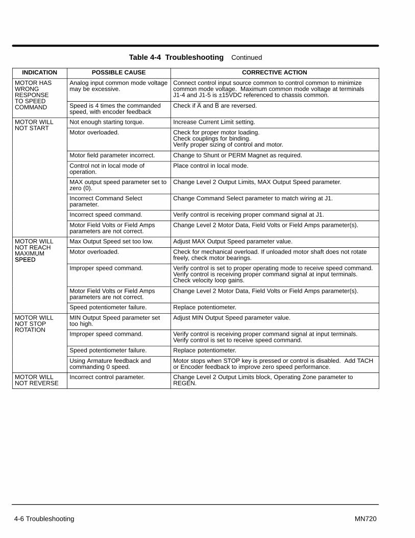
Section 1General Information
4-6 Troubleshooting MN720
Table 4-4 Troubleshooting Continued
INDICATION POSSIBLE CAUSE CORRECTIVE ACTION
MOTOR HASWRONGRESPONSE
Analog input common mode voltagemay be excessive.
Connect control input source common to control common to minimizecommon mode voltage. Maximum common mode voltage at terminalsJ1-4 and J1-5 is ±15VDC referenced to chassis common.
TO SPEEDCOMMAND Speed is 4 times the commanded
speed, with encoder feedbackCheck if A and B are reversed.
MOTOR WILL Not enough starting torque. Increase Current Limit setting.NOT START
Motor overloaded. Check for proper motor loading.Check couplings for binding.Verify proper sizing of control and motor.
Motor field parameter incorrect. Change to Shunt or PERM Magnet as required.
Control not in local mode ofoperation.
Place control in local mode.
MAX output speed parameter set tozero (0).
Change Level 2 Output Limits, MAX Output Speed parameter.
Incorrect Command Selectparameter.
Change Command Select parameter to match wiring at J1.
Incorrect speed command. Verify control is receiving proper command signal at J1.
Motor Field Volts or Field Ampsparameters are not correct.
Change Level 2 Motor Data, Field Volts or Field Amps parameter(s).
MOTOR WILL Max Output Speed set too low. Adjust MAX Output Speed parameter value.NOT REACHMAXIMUMSPEED
Motor overloaded. Check for mechanical overload. If unloaded motor shaft does not rotatefreely, check motor bearings.SPEED
Improper speed command. Verify control is set to proper operating mode to receive speed command.Verify control is receiving proper command signal at input terminals.Check velocity loop gains.
Motor Field Volts or Field Ampsparameters are not correct.
Change Level 2 Motor Data, Field Volts or Field Amps parameter(s).
Speed potentiometer failure. Replace potentiometer.
MOTOR WILLNOT STOP
MIN Output Speed parameter settoo high.
Adjust MIN Output Speed parameter value.
ROTATIONImproper speed command. Verify control is receiving proper command signal at input terminals.
Verify control is set to receive speed command.
Speed potentiometer failure. Replace potentiometer.
Using Armature feedback andcommanding 0 speed.
Motor stops when STOP key is pressed or control is disabled. Add TACHor Encoder feedback to improve zero speed performance.
MOTOR WILLNOT REVERSE
Incorrect control parameter. Change Level 2 Output Limits block, Operating Zone parameter toREGEN.
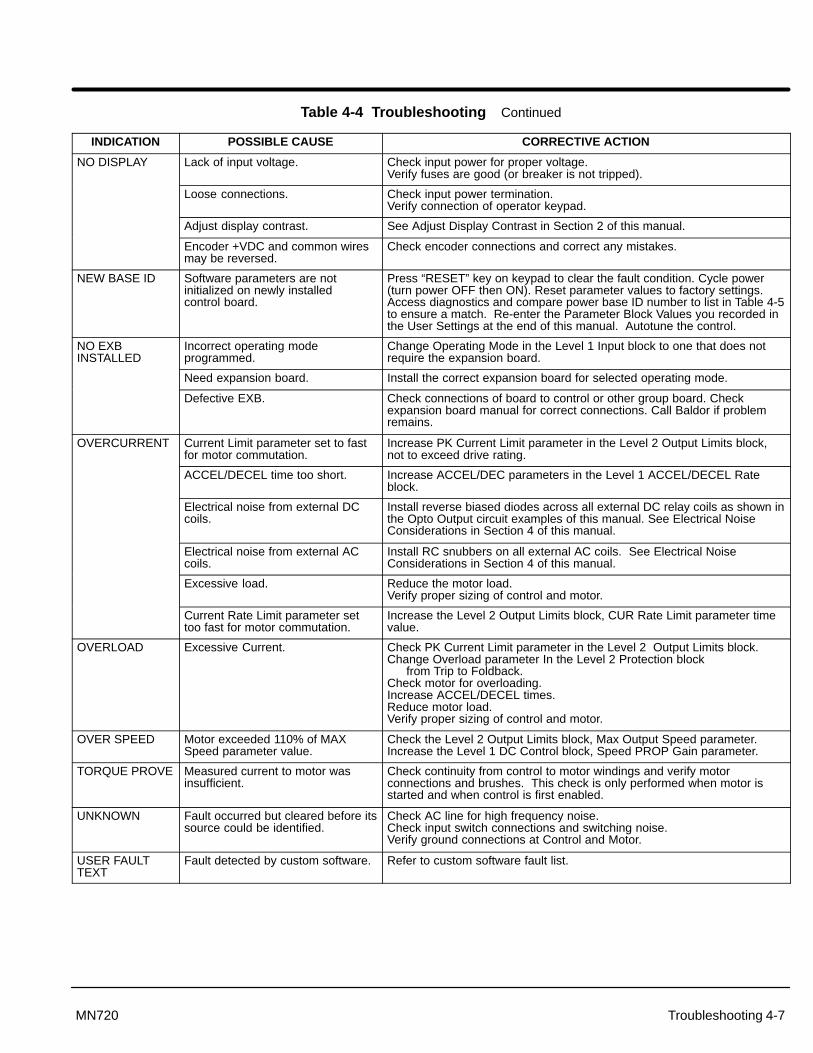
Section 1General Information
Troubleshooting 4-7MN720
Table 4-4 Troubleshooting Continued
INDICATION POSSIBLE CAUSE CORRECTIVE ACTION
NO DISPLAY Lack of input voltage. Check input power for proper voltage. Verify fuses are good (or breaker is not tripped).
Loose connections. Check input power termination.Verify connection of operator keypad.
Adjust display contrast. See Adjust Display Contrast in Section 2 of this manual.
Encoder +VDC and common wiresmay be reversed.
Check encoder connections and correct any mistakes.
NEW BASE ID Software parameters are notinitialized on newly installed control board.
Press “RESET” key on keypad to clear the fault condition. Cycle power(turn power OFF then ON). Reset parameter values to factory settings.Access diagnostics and compare power base ID number to list in Table 4-5to ensure a match. Re-enter the Parameter Block Values you recorded inthe User Settings at the end of this manual. Autotune the control.
NO EXBINSTALLED
Incorrect operating modeprogrammed.
Change Operating Mode in the Level 1 Input block to one that does notrequire the expansion board.
Need expansion board. Install the correct expansion board for selected operating mode.
Defective EXB. Check connections of board to control or other group board. Checkexpansion board manual for correct connections. Call Baldor if problemremains.
OVERCURRENT Current Limit parameter set to fastfor motor commutation.
Increase PK Current Limit parameter in the Level 2 Output Limits block, not to exceed drive rating.
ACCEL/DECEL time too short. Increase ACCEL/DEC parameters in the Level 1 ACCEL/DECEL Rateblock.
Electrical noise from external DCcoils.
Install reverse biased diodes across all external DC relay coils as shown inthe Opto Output circuit examples of this manual. See Electrical NoiseConsiderations in Section 4 of this manual.
Electrical noise from external ACcoils.
Install RC snubbers on all external AC coils. See Electrical NoiseConsiderations in Section 4 of this manual.
Excessive load. Reduce the motor load.Verify proper sizing of control and motor.
Current Rate Limit parameter settoo fast for motor commutation.
Increase the Level 2 Output Limits block, CUR Rate Limit parameter timevalue.
OVERLOAD Excessive Current. Check PK Current Limit parameter in the Level 2 Output Limits block.Change Overload parameter In the Level 2 Protection block
from Trip to Foldback.Check motor for overloading.Increase ACCEL/DECEL times.Reduce motor load.Verify proper sizing of control and motor.
OVER SPEED Motor exceeded 110% of MAXSpeed parameter value.
Check the Level 2 Output Limits block, Max Output Speed parameter.Increase the Level 1 DC Control block, Speed PROP Gain parameter.
TORQUE PROVE Measured current to motor wasinsufficient.
Check continuity from control to motor windings and verify motorconnections and brushes. This check is only performed when motor isstarted and when control is first enabled.
UNKNOWN Fault occurred but cleared before itssource could be identified.
Check AC line for high frequency noise.Check input switch connections and switching noise.Verify ground connections at Control and Motor.
USER FAULTTEXT
Fault detected by custom software. Refer to custom software fault list.
Section 1General Information
4-8 Troubleshooting MN720
Table 4-5 Power Base ID - Series 20H
130VAC ControlCatalog Numbers
PowerBase 230VAC Control
Catalog Numbers
PowerBase
460VAC ControlCatalog Numbers
PowerBase
IDCatalog Numbers ID Catalog Numbers IDBC20H410–CL 13C
BC20H103–CL F1 BC20H205–CL 0F2 BC20H420–CL 144BC20H107–CL F9 BC20H210–CL 0FA BC20H430–CL 14CBC20H110–CL 101 BC20H215–CL 102 BC20H440–CL 154BC20H115–CL 109 BC20H220–CL 10A BC20H450–CL 15CBC20H120–CL 111 BC20H225–CL 112 BC20H475–CL 164BC20H125–CL 119 BC20H240–CL 11A BC20H4100–CL 16CBC20H135–CL 121 BC20H250–CL 112 BC20H4125–CL 174BC20H140–CL 129 BC20H260–CL 12A BC20H4150–CL 17CBC20H150–CL 131 BC20H275–CL 132 BC20H4200–CL 1A4
BC20H2125–CL 182 BC20H4250–CL 184BC20H4300–CL 18CBC20H4400–EL 1ACBC20H4500–EL 194BC20H4600–EL 19C
Note: The Power Base ID number of a control is displayed in a DiagnosticInformation screen as a hexadecimal value.
Section 1General Information
Troubleshooting 4-9MN720
Control Circuit Board Test Points
Figure 4-1 Test Point Description
JP11 2 3
Pins Command Signal1&2 Voltage2&3 4-20mA
J6 Test Points
AV ARM Volts (5VDC=+1000, 2.5VDC=0, 0VDC=–1000)AI ARM Current (5VDC=125% at Rating, 0VDC=–125% at RatingFI Field Current (5VDC=50 AT, 0VDC=0 AT)TH Heatsink Temperature (4VDC=100°C)GND Ground
Section 1General Information
4-10 Troubleshooting MN720
Electrical Noise Considerations All electronic devices are vulnerable to significant electronic interference signals(commonly called “Electrical Noise”). At the lowest level, noise can cause intermittentoperating errors or faults. From a circuit standpoint, 5 or 10 millivolts of noise may causeabnormal operation.
At the extreme level, significant noise can cause damage to the drive. Therefore, it isadvisable to prevent noise generation and to follow wiring practices that prevent noisegenerated by other devices from reaching sensitive circuits. In a control, such circuitsinclude inputs for speed, torque, control logic, and speed and position feedback, plusoutputs to some indicators and computers.
Relay and Contactor Coils Among the most common sources of noise is the coil of a contactor or a relay. Whenthese highly inductive coil circuits are opened, transient conditions often generate spikesof several hundred volts in the control circuit. These spikes can induce several volts ofnoise in an adjacent wire that runs parallel to a control–circuit wire.
Figure 4-2 illustrates noise suppression for AC and DC operated coils.
Figure 4-2 AC & DC Coil Noise Suppression
AC Coil DC Coil
RC snubber
0.47 �FDiode
–
33 �
+
Wires between Controls and Motors
Output leads from a typical 460 VAC drive controller contain rapid voltage rises createdby power semiconductors switching 650V in less than a microsecond, 1,000 to 10,000times a second. These noise signals can couple into sensitive drive circuits. If shieldedpair cable is used, the coupling is reduced by nearly 90% compared to unshielded cable.
Even input AC power lines contain noise and can induce noise in adjacent wires. Insome cases, line reactors may be required.
To prevent induced transient noise in signal wires, all motor leads and AC power linesshould be contained in rigid metal conduit, or flexible conduit. Do not place lineconductors and load conductors in same conduit. Use one conduit for 3 phase inputwires and another conduit for the motor leads. The conduits should be grounded to forma shield to contain the electrical noise within the conduit path. Signal wires - even ones inshielded cable should never be placed in the conduit with motor power wires.

Section 1General Information
Troubleshooting 4-11MN720
Electrical Noise Considerations Continued
Special Drive SituationsFor severe noise situations, it may be necessary to reduce transient voltages in the wiresto the motor by adding load reactors. Load reactors are installed between the control andmotor.
Reactors are typically 3% reactance and are designed for the frequencies encountered inPWM drives. For maximum benefit, the reactors should be mounted in the driveenclosure with short leads between the control and the reactors.
Control Enclosures Motor controls mounted in a grounded enclosure should also be connected to earthground with a separate conductor to ensure best ground connection. Often groundingthe control to the grounded metallic enclosure is not sufficient. Usually painted surfacesand seals prevent solid metallic contact between the control and the panel enclosure.Likewise, conduit should never be used as a ground conductor for motor power wires orsignal conductors.
Special Motor Considerations Motor frames must also be grounded. As with control enclosures, motors must begrounded directly to the control and plant ground with as short a ground wire as possible.Capacitive coupling within the motor windings produces transient voltages between themotor frame and ground. The severity of these voltages increases with the length of theground wire. Installations with the motor and control mounted on a common frame, andwith heavy ground wires less than 10 ft. long, rarely have a problem caused by thesemotor–generated transient voltages.
Sometimes motor frame transient voltages are capacitively coupled to feedback devicesmounted on the motor shaft. To prevent this problem, add electrical isolation betweenthe motor and the feedback device. The most simple isolation method, shown in FigureNO TAG, has two parts: 1) A plate of electrical insulating material placed between themotor mounting surface and the feedback device. 2) An insulating coupling betweenmotor shaft and the shaft of the feedback device.
Figure 4-3 Isolated Mounting Method
Insulating plate
Insulating Coupling
Encoder or otherfeedback device
Mounting bracket
Analog Signal Wires Analog signals generally originate from speed and torque controls, plus DC tachometersand process controllers. Reliability is often improved by the following noise reductiontechniques:
• Use twisted-pair shielded wires with the shield grounded at the drive end only.• Route analog signal wires away from power or control wires (all other wiring types).• Cross power and control wires at right angles (90°) to minimize inductive noise
coupling.

Section 1General Information
4-12 Troubleshooting MN720
Electrical Noise Considerations Continued
Wiring PracticesThe type of wire used and how it is installed for specific applications makes the differencebetween obtaining reliable operation and creating additional problems.
Power Wiring Conductors carrying power to anything (motor, heater, brake coil, or lighting units, forexample) should be contained in conductive conduit that is grounded at both ends.These power wires must be routed in conduit separately from signal and control wiring.
Control–logic Conductors Typically, operator’s controls (push buttons and switches), relay contacts, limit switches,PLC I/O’s, operator displays, and relay and contactor coils operate at 115VAC or 24VDC.Although these devices usually operate at low current levels, they contain switching noisecaused by contact open/closure and solid–state switch operations. Therefore, these wiresshould be routed away from sensitive signal wires and contained within conduits orbundled away from open power and signal wires.
DC Tachometer Circuits Among the most sensitive circuits is the DC Tachometer. Reliability of a DC tachometercircuit is often improved by the following noise reduction techniques:
• Connect a 0.1 �F capacitor across the tachometer terminals to suppress ACnoise.
• Use twisted-pair shielded wires with the shield grounded at the control end only.You should avoid grounding the shield to the tachometer case or conduit.
• Follow the practices for analog signal wiring.
Analog Signal Wires Analog signals generally originate from speed and torque controls, plus DC tachometersand process controllers. Reliability is often improved by the following noise reductiontechniques:
• Use twisted-pair shielded wires with the shield grounded at the drive end only.
• Route analog signal wires away from power or control wires (all other wiringtypes).
• Cross power and control wires at right angles (90°) to minimize inductive noisecoupling.
Encoder Circuits Adjustable speed drives are especially sensitive to high frequency noise on encodersignal lines. Because these input signals cannot be heavily filtered special care must betaken to avoid transient noise from entering these signal lines. Drive reliability can begreatly improved by using the following noise reduction techniques:
• Use line driver output encoders to reduce the encoder output impedance.
• Select line driver inputs on the adjustable speed drive.
• Install twisted-pair shielded wire for power to the encoder and having eachoutput with its own return. (Avoid common conductors with multiple outputs orwith an output and the power source.)
• Never connect the encoder ground to the power ground terminal of the control.
• Run all encoder wires independently from all other power wires.
Plant Ground Connecting electrical equipment to a good ground is essential for safety and reliableoperation. In many cases, what is perceived as a ground isn’t. Result: equipment malfunctions or electrical shock hazard exists.
It may be necessary to retain the services of an electrical consultant, who is also alicensed professional engineer experienced in grounding practices to make the necessarymeasurements to establish if the plant ground is really grounded.

Section 5Specifications and Product Data
Specifications and Product Data 5-1MN720
Specifications:
Enclosure: Open Type (Chassis Mount)
Horsepower 2-50 HP @ 115VAC3-125 HP @ 230VAC5-600 HP @ 460VAC
Input Frequency 50/60 HZ ± 5%
Output Voltage 0 to (1.13 x Input VAC)VDC (REGEN)0 to (1.30 x Input VAC)VDC (ONE-WAY)
Output Current See Ratings Table 5-1
Service Factor 1.0
Duty Continuous
Overload Capacity See Ratings Table 5-1
Rated Storage Temperature: – 30 °C to +65 °C
Operating Conditions:
Voltage Range: 115 VAC Models230 VAC Models460 VAC Models �
105-130 VAC 3� 60 Hz180-264 VAC 3� 60 Hz / 180-230 VAC 3� 50 Hz340-528 VAC 3� 60 Hz / 340-460 VAC 3� 50 Hz
Input Frequency Variation: ±5%, 8.0Hz/Second Maximum Slew Rate
Input Line Impedance: 5% Maximum
Ambient Operating Temperature: 0 to +40 °CDerate Output 2% per °C over 40 °C to 55 °C Max
Ambient Temperature: 0 °C to +40 °C
Humidity: 10 to 90% RH Non-Condensing
Altitude: Sea level to 3300 Feet (1000 Meters)Derate 2% per 1000 Feet (303 Meters) above 3300 Feet
Shock: 1G
Vibration: 0.5G at 10Hz to 60Hz
� 460VAC control requires 230VAC 1� for cooling fans on some B and C size controls. See Table 5-1.
Section 1General Information
5-2 Specifications and Product Data MN720
Keypad Display:
Display Backlit LCD Alphanumeric 2 Lines x 16 Characters
Keys 12 key membrane with tactile response
Functions Output status monitoringDigital speed controlParameter setting and displayDiagnostic and Fault log displayMotor run and jogLocal/Remote toggle
LED Indicators Forward run commandReverse run commandStop commandJog active
Remote Mount 100 feet (30.3m) max from control
Control Specifications:
Control Method Three phase, full wave, bi-directional regenerative DC control with 6total pulses per cycle and 6 controlled pulses per cycle. NEMA Type C.
Speed Regulation Feedback Type:ArmatureEncoderTachometer (optional)Resolver (optional)
1% of base speed0.1% of set speed1% of set speed0.1% of set speed
Current (Rate Limit) - Time to peak current 0.008 Seconds - 1.0 Seconds
Accel / Decel Time 0 - 3600 Seconds for 2 assignable presets plus JOG
S-Curve Time 0 - 100%
JOG Speed 0 - Maximum speed
Minimum Output Speed 0 - Maximum speed
Maximum Output Speed 0 - Maximum speed
Auto Restart Manual or Automatic
IR Compensation Gain Available for Armature Feedback
Velocity Loop Bandwidth Adjustable to 20Hz
Current Loop Bandwidth Adjustable to 70Hz
Selectable Operating Modes KeypadStandard Run 3 Wire2 Wire Control with 15 PresetsSerialBipolar Speed/Torque Process ModeBipolar HoistSeven Speed Hoist, 2 Wire

Section 1General Information
Specifications and Product Data 5-3MN720
Field Power Supply:
Type Voltage Limited, Current Regulated Full Wave Single Phase
Voltage 0-85% of AC Line Input (in DC Volts)
Current 0.1 - 15 Amperes maximum standard (Standard to 300HP)0.3 - 40 Amperes maximum optional (Standard ≥400HP)Off for Permanent Magnet Motors
Field Economy Level Off, 25 - 100%
Field Forcing Level (hoist modes only) 100 - 125%
Differential Analog Input:
Common Mode Rejection 40 db
Full Scale Range ±5VDC, ±10VDC, 4-20 mA
Auto-selectable Resolutions 12 bits + sign below 1VDC command 9 bits + sign above 1VDC command
Update rate 2.7 msec with a 60Hz line
Other Analog Input:
Full Scale Range ±10 VDC
Resolution 9 bits + sign
Update Rate 2.7 msec with a 60Hz line
Analog Outputs:
Analog Outputs 2 Assignable
Full Scale Range 0 - 5 VDC
Source Current 1 mA maximum
Resolution 8 bits
Update Rate 2.7 msec with a 60Hz line
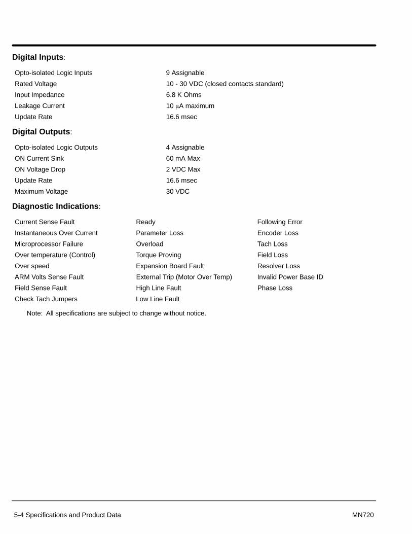
Section 1General Information
5-4 Specifications and Product Data MN720
Digital Inputs:
Opto-isolated Logic Inputs 9 Assignable
Rated Voltage 10 - 30 VDC (closed contacts standard)
Input Impedance 6.8 K Ohms
Leakage Current 10 �A maximum
Update Rate 16.6 msec
Digital Outputs:
Opto-isolated Logic Outputs 4 Assignable
ON Current Sink 60 mA Max
ON Voltage Drop 2 VDC Max
Update Rate 16.6 msec
Maximum Voltage 30 VDC
Diagnostic Indications:
Current Sense Fault Ready Following Error
Instantaneous Over Current Parameter Loss Encoder Loss
Microprocessor Failure Overload Tach Loss
Over temperature (Control) Torque Proving Field Loss
Over speed Expansion Board Fault Resolver Loss
ARM Volts Sense Fault External Trip (Motor Over Temp) Invalid Power Base ID
Field Sense Fault High Line Fault Phase Loss
Check Tach Jumpers Low Line Fault
Note: All specifications are subject to change without notice.

Section 1General Information
Specifications and Product Data 5-5MN720
Ratings
Table 5-1 Ratings
Max. OutputInputVAC
CatalogNumber Volts HP KW RMS
AmpsPeakAmps
Size Cooling BlowerVoltage
Blower PowerRequirement
115 BC20H103–CL 140 3 2.2 20 60 A – –115 BC20H107–CL 140 7 5.2 40 120 A – –115 BC20H110–CL 140 10 7.5 60 150 A – –115 BC20H115–CL 140 15 11.2 75 190 B – –115 BC20H120–CL 140 20 14.9 100 250 B � 115VAC 1x24 Watt115 BC20H125–CL 140 25 18.6 140 420 C � 115VAC 2x24 Watt115 BC20H135–CL 140 35 26 180 480 C � 115VAC 2x24 Watt115 BC20H140–CL 140 40 29.8 210 540 C � 115VAC 2x24 Watt115 BC20H150–CL 140 50 37.3 270 680 C � 115VAC 1x1.9 Watt230 BC20H205–CL 240 5 3.7 20 60 A – –230 BC20H210–CL 240 10 7.5 40 120 A – –230 BC20H215–CL 240 15 11.2 60 150 A – –230 BC20H220–CL 240 20 14.9 75 190 B – –230 BC20H225–CL 240 25 18.6 100 250 B 230 VAC 1x24 Watt230 BC20H240–CL 240 40 29.8 140 420 C 230 VAC 2x24 Watt230 BC20H250–CL 240 50 37.3 180 480 C 230 VAC 2x24 Watt230 BC20H260–CL 240 60 44.8 210 540 C 230 VAC 2x24 Watt230 BC20H275–CL 240 75 56 270 680 C 230/460 VAC 1x.95A/.48A230 BC20H2125–CL 240 125 93 420 1050 D 230/460 VAC 1x.95A/.48A460 BC20H410–CL 500 10 7.5 20 60 A – –460 BC20H420–CL 500 20 14.9 40 120 A – –460 BC20H430–CL 500 30 22.4 60 150 A – –460 BC20H440–CL 500 40 29.8 75 190 B – –460 BC20H450–CL 500 50 37.3 100 250 B � 115VAC 1x24 Watt460 BC20H475–CL 500 75 56 140 420 C 230/460VAC 1x.95A/.48A460 BC20H4100–CL 500 100 74.6 180 480 C 230/460VAC 1x.95A/.48A460 BC20H4125–CL 500 125 93 210 530 C 230/460VAC 1x.95A/.48A460 BC20H4150–CL 500 150 112 270 680 C 230/460VAC 1x.95A/.48A460 BC20H4200–CL 500 200 149 350 875 D 230/460VAC 1x.95A/.48A460 BC20H4250–CL 500 250 187 420 1050 D 230/460VAC 1x.95A/.48A460 BC20H4300–CL 500 300 224 500 1250 D 230/460VAC 1x.95A/.48A460 BC20H4400–EL 500 400 298 670 1340 G – Internal Connection460 BC20H4500–EL 500 500 373 840 1680 G – Internal Connection460 BC20H4600–EL 500 600 448 960 1920 G – Internal Connection
� Controls built before 2nd quarter 1996 have 230VAC fans.
Peak Amps are Rated for 3 Seconds Maximum. 150% of motor amps – 60 seconds 200% of motor amps – 8 seconds 300% of motor amps – 3 seconds (Within peak current capacity limits of control)
Note: All specifications are subject to change without notice.
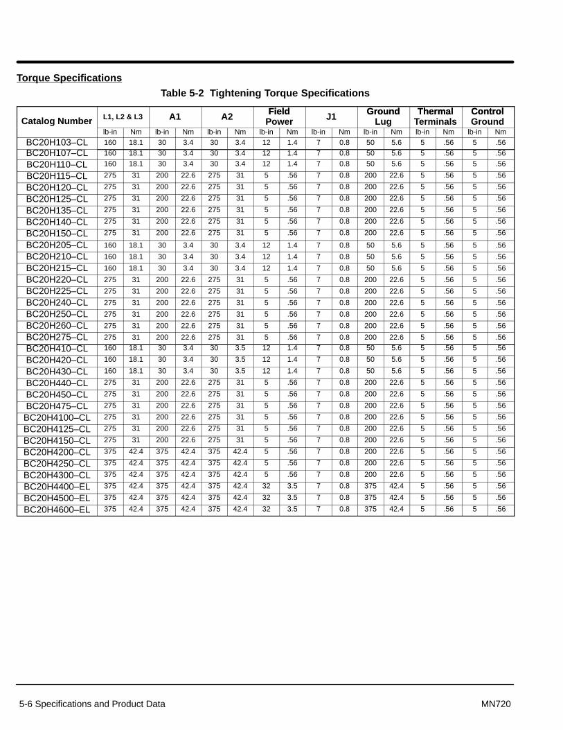
Section 1General Information
5-6 Specifications and Product Data MN720
Torque Specifications
Table 5-2 Tightening Torque Specifications
Field Ground Thermal ControlCatalog Number L1, L2 & L3 A1 A2 Field
Power J1 GroundLug
ThermalTerminals
ControlGround
lb-in Nm lb-in Nm lb-in Nm lb-in Nm lb-in Nm lb-in Nm lb-in Nm lb-in Nm
BC20H103–CL 160 18.1 30 3.4 30 3.4 12 1.4 7 0.8 50 5.6 5 .56 5 .56
BC20H107–CL 160 18.1 30 3.4 30 3.4 12 1.4 7 0.8 50 5.6 5 .56 5 .56
BC20H110–CL 160 18.1 30 3.4 30 3.4 12 1.4 7 0.8 50 5.6 5 .56 5 .56
BC20H115–CL 275 31 200 22.6 275 31 5 .56 7 0.8 200 22.6 5 .56 5 .56
BC20H120–CL 275 31 200 22.6 275 31 5 .56 7 0.8 200 22.6 5 .56 5 .56
BC20H125–CL 275 31 200 22.6 275 31 5 .56 7 0.8 200 22.6 5 .56 5 .56
BC20H135–CL 275 31 200 22.6 275 31 5 .56 7 0.8 200 22.6 5 .56 5 .56
BC20H140–CL 275 31 200 22.6 275 31 5 .56 7 0.8 200 22.6 5 .56 5 .56
BC20H150–CL 275 31 200 22.6 275 31 5 .56 7 0.8 200 22.6 5 .56 5 .56
BC20H205–CL 160 18.1 30 3.4 30 3.4 12 1.4 7 0.8 50 5.6 5 .56 5 .56
BC20H210–CL 160 18.1 30 3.4 30 3.4 12 1.4 7 0.8 50 5.6 5 .56 5 .56
BC20H215–CL 160 18.1 30 3.4 30 3.4 12 1.4 7 0.8 50 5.6 5 .56 5 .56
BC20H220–CL 275 31 200 22.6 275 31 5 .56 7 0.8 200 22.6 5 .56 5 .56
BC20H225–CL 275 31 200 22.6 275 31 5 .56 7 0.8 200 22.6 5 .56 5 .56
BC20H240–CL 275 31 200 22.6 275 31 5 .56 7 0.8 200 22.6 5 .56 5 .56
BC20H250–CL 275 31 200 22.6 275 31 5 .56 7 0.8 200 22.6 5 .56 5 .56
BC20H260–CL 275 31 200 22.6 275 31 5 .56 7 0.8 200 22.6 5 .56 5 .56
BC20H275–CL 275 31 200 22.6 275 31 5 .56 7 0.8 200 22.6 5 .56 5 .56
BC20H410–CL 160 18.1 30 3.4 30 3.5 12 1.4 7 0.8 50 5.6 5 .56 5 .56
BC20H420–CL 160 18.1 30 3.4 30 3.5 12 1.4 7 0.8 50 5.6 5 .56 5 .56
BC20H430–CL 160 18.1 30 3.4 30 3.5 12 1.4 7 0.8 50 5.6 5 .56 5 .56
BC20H440–CL 275 31 200 22.6 275 31 5 .56 7 0.8 200 22.6 5 .56 5 .56
BC20H450–CL 275 31 200 22.6 275 31 5 .56 7 0.8 200 22.6 5 .56 5 .56
BC20H475–CL 275 31 200 22.6 275 31 5 .56 7 0.8 200 22.6 5 .56 5 .56
BC20H4100–CL 275 31 200 22.6 275 31 5 .56 7 0.8 200 22.6 5 .56 5 .56
BC20H4125–CL 275 31 200 22.6 275 31 5 .56 7 0.8 200 22.6 5 .56 5 .56
BC20H4150–CL 275 31 200 22.6 275 31 5 .56 7 0.8 200 22.6 5 .56 5 .56
BC20H4200–CL 375 42.4 375 42.4 375 42.4 5 .56 7 0.8 200 22.6 5 .56 5 .56
BC20H4250–CL 375 42.4 375 42.4 375 42.4 5 .56 7 0.8 200 22.6 5 .56 5 .56
BC20H4300–CL 375 42.4 375 42.4 375 42.4 5 .56 7 0.8 200 22.6 5 .56 5 .56
BC20H4400–EL 375 42.4 375 42.4 375 42.4 32 3.5 7 0.8 375 42.4 5 .56 5 .56
BC20H4500–EL 375 42.4 375 42.4 375 42.4 32 3.5 7 0.8 375 42.4 5 .56 5 .56
BC20H4600–EL 375 42.4 375 42.4 375 42.4 32 3.5 7 0.8 375 42.4 5 .56 5 .56
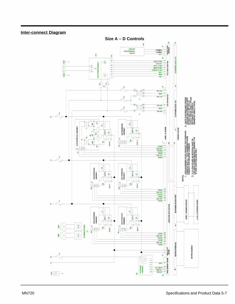
Section 1General Information
Specifications and Product Data 5-7MN720
Inter-connect Diagram
Size A – D Controls
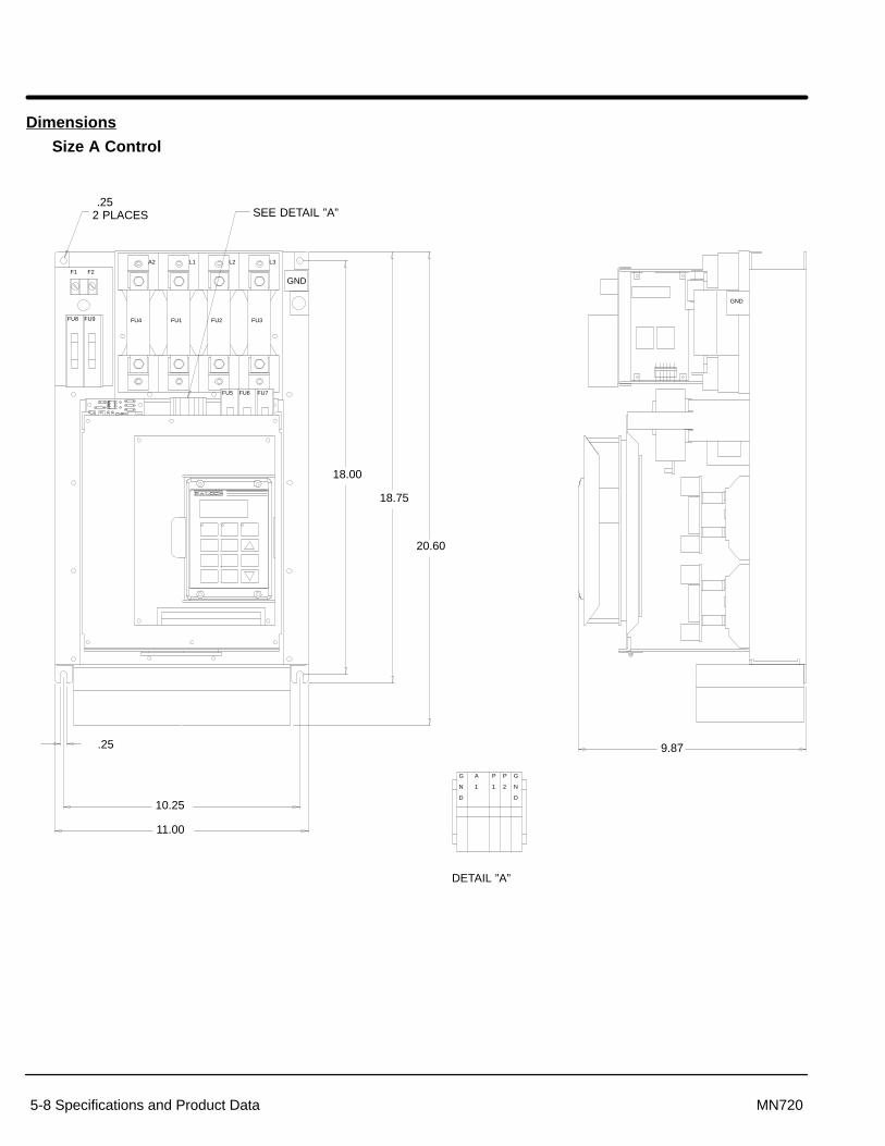
Section 1General Information
5-8 Specifications and Product Data MN720
Dimensions
Size A Control
GND
11.00
10.25
18.75
18.00
9.87
20.60
2 PLACES
.25
FU4 FU1 FU2 FU3
GND
F1 F2
A2 L1 L2 L3
FU5 FU6 FU7
G
N
D
A
1
P
1
P
2
G
N
D
DETAIL ”A”
SEE DETAIL ”A”
FU8 FU9
.25
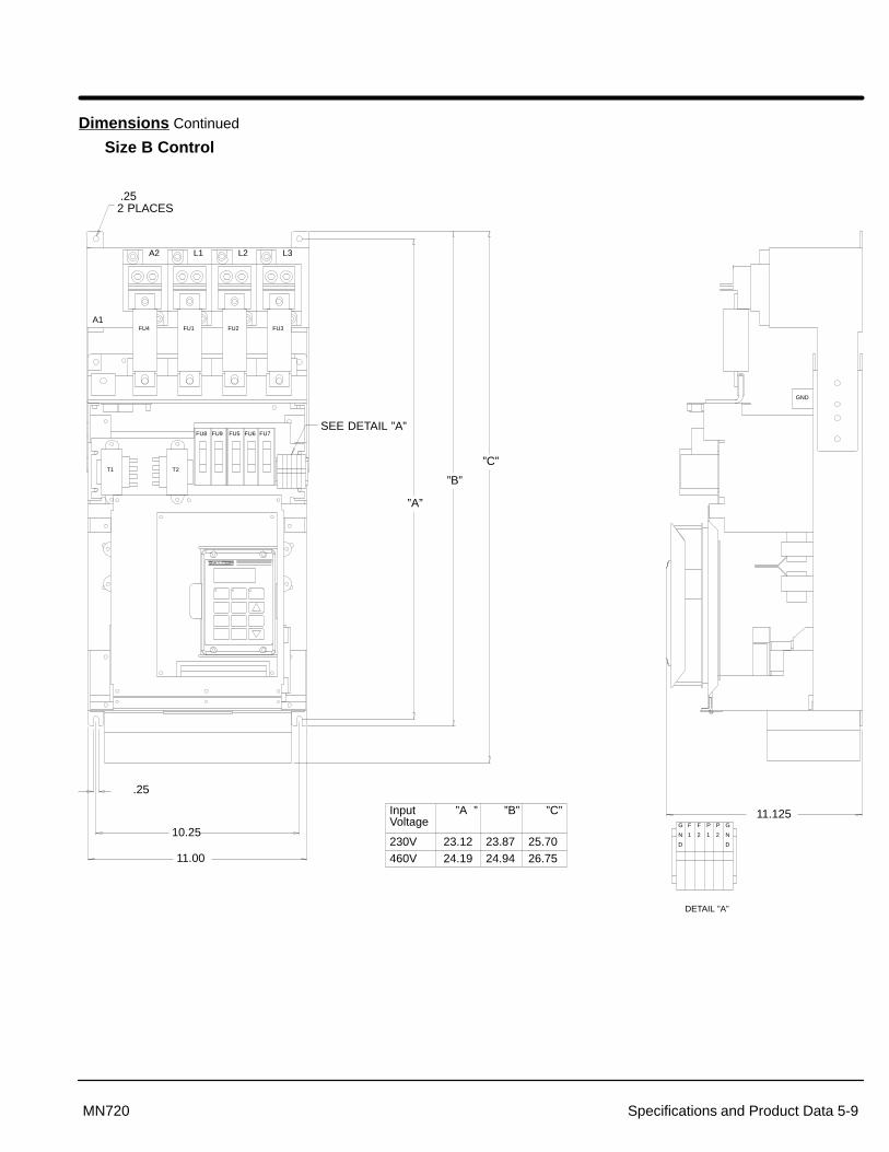
Section 1General Information
Specifications and Product Data 5-9MN720
Dimensions Continued
Size B Control
A2 L1 L2 L3
A1
10.25
11.00
”A”
”B”
”C”
2 PLACES
.25
GND
FU4 FU1 FU2 FU3
11.125
T1 T2
FU8 FU9 FU5 FU6 FU7
G
N
D
F
1
F
2
P
1
P
2
G
N
D
SEE DETAIL ”A”
DETAIL ”A”
Input ”A ” ”B” ”C”Voltage
230V 23.12 23.87 25.70460V 24.19 24.94 26.75
.25
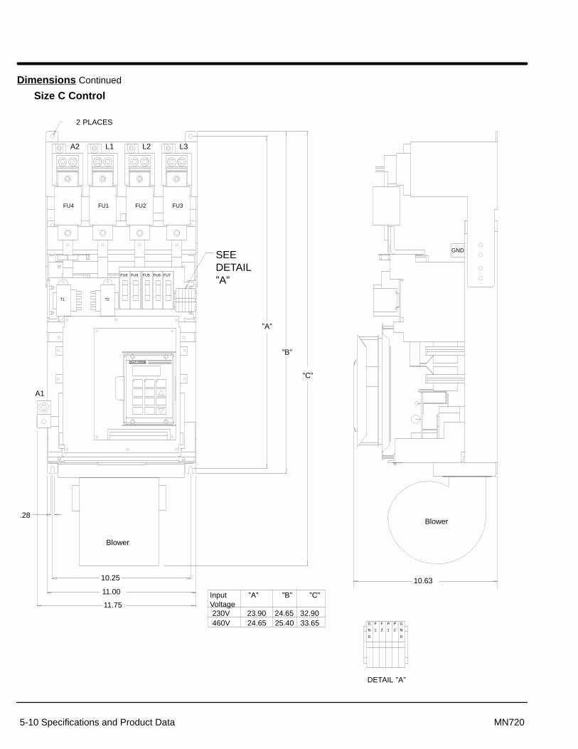
Section 1General Information
5-10 Specifications and Product Data MN720
Dimensions Continued
Size C Control
A2 L1 L2 L3
10.25
11.00
11.75
”A”
”C”
”B”
2 PLACES
10.63
FU4 FU1 FU2 FU3
A1
GND
T1 T2
FU8 FU9 FU5 FU6 FU7
G
N
D
F
1
F
2
P
1
P
2
G
N
D
DETAIL ”A”
SEE DETAIL”A”
Input ”A” ”B” ”C” Voltage230V 23.90 24.65 32.90460V 24.65 25.40 33.65
.28
Blower
Blower

Section 1General Information
Specifications and Product Data 5-11MN720
Dimensions Continued
Size D Control
43.80
40.00
39.25
.38
15.19
13.75.72
A2 L1 L2 L3
A1
12.06
12.43
16.87
Blower Blower

Section 1General Information
5-12 Specifications and Product Data MN720
Dimensions Continued
Size G Control
3.72(94,6)
2.66(67,6)
Removable ConduitMounting Plates(Customer Power Connections)
24.00(609,6)
23.63(600)
8.63 (219)
8.63 (219)12.41 (315)
31.50(800)
90.55(2300)
93.00(2362)
4.00(101,6)
47.25(1200)
AirOutletGrill
Air InletGrills (6)

Appendix A
Appendix A-1MN720
Field Supply ModuleThe standard field supply modules provide up to 85% of the incoming AC voltage as itsmaximum DC output voltage. Standard output current is 15 amps mounted to the controlchassis with an optional separately mounted 40 amp maximum supply available fromBaldor Electric.
It is possible to run motors with fields above 85% of the incoming AC voltage with theSeries 20H control. Doing so requires a voltage step–up transformer to be addedbetween the field supply module’s Ll – L2 connection. Note that this connection is phasesensitive with Ll and L2. Maximum AC input voltage to the field supply module should belimited to 528 VAC on 60 Hz.
Required step up transformer is calculated:
Minimum AC Input Volts �Required Maximum Motor Field Voltage
0.85
Example:
Motor field volts required is 300 VDC, AC input is 230 VAC
Required Maximum Motor Field Voltage0.85
� 3000.85
� 366VAC Minimum AC Input
Minimum step–up ratio for the transformer is calculated:
Calculated Minimum AC Input VoltsAC Line Input Volts
Transformer KVA is calculated by:
Transformer KVA = Max Field Volts x Max Field Amps
In the case of the voltage step–up transformer, the FIELD RATED VOLTS parametershould be calculated by:
Field Rated Volts � Rated Field Volts �Input Volts
Output Volts
Example from above:
Field Rated Volts � 300VDC ��230366� � 188VDC

Section 1General Information
A-2 Appendix MN720
The standard field connection is shown in Figure A-1.
Figure A-1 Standard Field Connection
L1
L2
L3
L1
L2
F+
F–
A10Field Power Module
FieldVolts DC
L1
L2
L3
Series 20HControl
When using a transformer to boost the AC input to the field supply module to get a fieldvoltage more than 85% of the AC line will be connected as shown in Figure A-2.
Figure A-2 Field Transformer Connection (to increase field output voltage)�1
�2
�3
L1
L2
F+
F–
A10Field Power Module
FieldVolts DC
�1
�2
�3
Series 20HControl
�
ControlTransformer
� Note that the wire that connects �2 with L2 of the Field Power Module isremoved and the control transformer is connected.
1. Output field voltage is adjusted as specified for the application.
2. Maximum Motor Field Voltage = 0.85 x V L1-L2
3. VL1�L2 � V �1��2 � N � V �1��2
Where N=Control transformer voltage ratio (Secondary/Primary)
4. Minimum control transformer VA rating = (Maximum Field Amps DC) x NV�1-�2
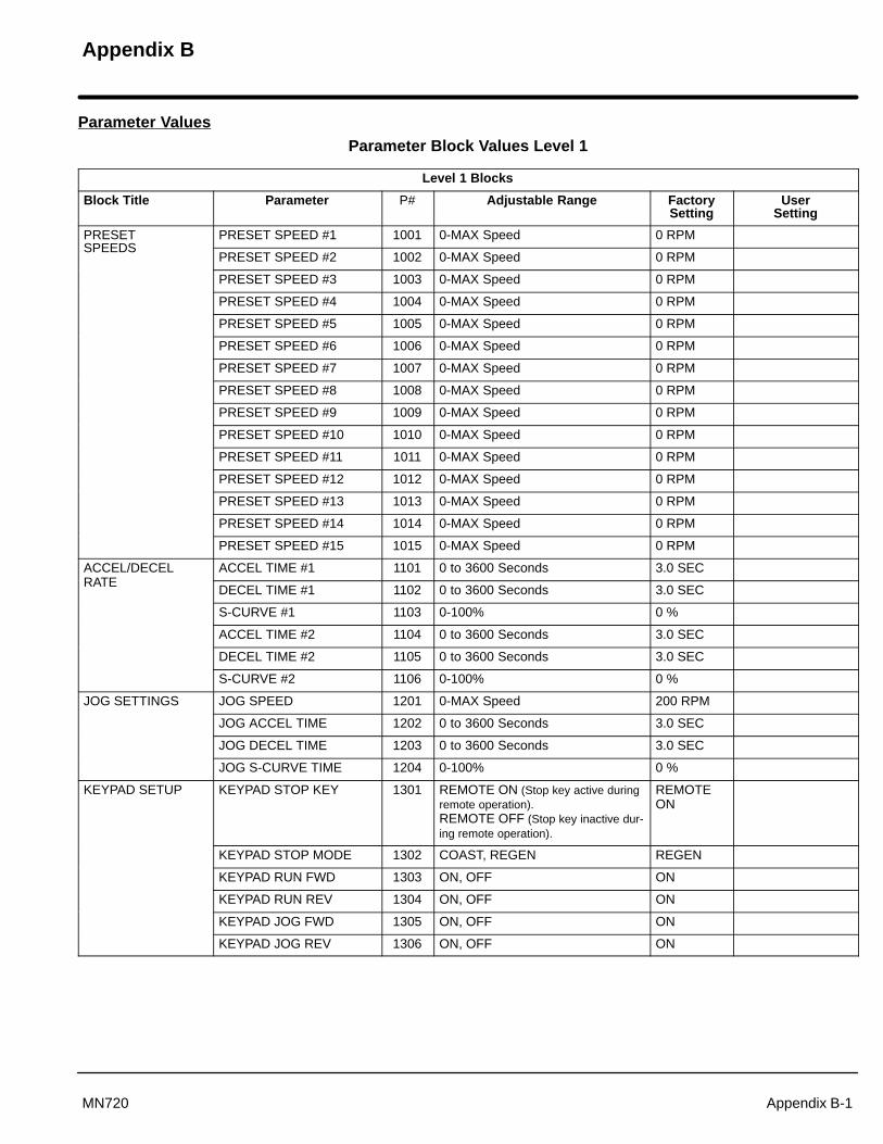
Appendix B
Appendix B-1MN720
Parameter Values
Parameter Block Values Level 1
Level 1 Blocks
Block Title Parameter P# Adjustable Range FactorySetting
UserSetting
PRESET PRESET SPEED #1 1001 0-MAX Speed 0 RPMSPEEDS
PRESET SPEED #2 1002 0-MAX Speed 0 RPM
PRESET SPEED #3 1003 0-MAX Speed 0 RPM
PRESET SPEED #4 1004 0-MAX Speed 0 RPM
PRESET SPEED #5 1005 0-MAX Speed 0 RPM
PRESET SPEED #6 1006 0-MAX Speed 0 RPM
PRESET SPEED #7 1007 0-MAX Speed 0 RPM
PRESET SPEED #8 1008 0-MAX Speed 0 RPM
PRESET SPEED #9 1009 0-MAX Speed 0 RPM
PRESET SPEED #10 1010 0-MAX Speed 0 RPM
PRESET SPEED #11 1011 0-MAX Speed 0 RPM
PRESET SPEED #12 1012 0-MAX Speed 0 RPM
PRESET SPEED #13 1013 0-MAX Speed 0 RPM
PRESET SPEED #14 1014 0-MAX Speed 0 RPM
PRESET SPEED #15 1015 0-MAX Speed 0 RPM
ACCEL/DECEL ACCEL TIME #1 1101 0 to 3600 Seconds 3.0 SECRATE
DECEL TIME #1 1102 0 to 3600 Seconds 3.0 SEC
S-CURVE #1 1103 0-100% 0 %
ACCEL TIME #2 1104 0 to 3600 Seconds 3.0 SEC
DECEL TIME #2 1105 0 to 3600 Seconds 3.0 SEC
S-CURVE #2 1106 0-100% 0 %
JOG SETTINGS JOG SPEED 1201 0-MAX Speed 200 RPM
JOG ACCEL TIME 1202 0 to 3600 Seconds 3.0 SEC
JOG DECEL TIME 1203 0 to 3600 Seconds 3.0 SEC
JOG S-CURVE TIME 1204 0-100% 0 %
KEYPAD SETUP KEYPAD STOP KEY 1301 REMOTE ON (Stop key active duringremote operation).REMOTE OFF (Stop key inactive dur-ing remote operation).
REMOTEON
KEYPAD STOP MODE 1302 COAST, REGEN REGEN
KEYPAD RUN FWD 1303 ON, OFF ON
KEYPAD RUN REV 1304 ON, OFF ON
KEYPAD JOG FWD 1305 ON, OFF ON
KEYPAD JOG REV 1306 ON, OFF ON

B-2 Appendix MN720
Parameter Block Values Level 1 Continued
Level 1 Blocks - Continued
Block Title Parameter P# Adjustable Range Factory UserSetting
INPUT OPERATING MODE 1401 KEYPADSTANDARD RUN15SPDSERIALBIPOLARPROCESS MODEBIPLOAR HOIST7 SPEED HOIST
KEYPAD
COMMAND SELECT 1402 POTENTIOMETER +/-10 VOLTS+/-5 VOLTS4 TO 20 mA10V W/EXT CL10V W/TORQ FFEXB PULSE FOL5V EXB10V EXB4-20mA EXB3-15 PSI EXBTACHOMETER EXBSERIALNONE
POTENTIO-METER
ANA CMD INVERSE 1403 ON, OFF OFF
ANA 2 OFFSET 1404 -20% TO +20% 0.0
ANA 2 DEADBAND 1405 0-10.00 V 0.20 V
OUTPUT OPTO OUTPUT #1 1501 READYZERO SPEED AT SPEEDOVERLOAD
READY
OPTO OUTPUT #2 1502OVERLOADKEYPAD CONTROLAT SET SPEEDFAULTFOLLOWING ERRMOTR DIRECTION
ZEROSPEED
OPTO OUTPUT #3 1503MOTR DIRECTIONDRIVE ONCMD DIRECTIONAT POSITIONOVER TEMP WARN
AT SPEED
OPTO OUTPUT #4 1504 RUNNING FIELDPROCESS ERRORDRIVE RUNM/FWD CONTACT
FAULT
ZERO SPD SET PT 1505 0-MAX Speed 200 RPM
AT SPEED BAND 1506 ±1000 RPM 100 RPM
SET SPEED 1507 0-MAX Speed Rated MotorSpeed
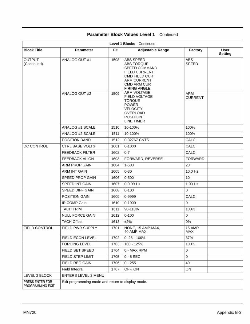
Appendix B-3MN720
Parameter Block Values Level 1 Continued
Level 1 Blocks - Continued
Block Title Parameter P# Adjustable Range Factory UserSetting
OUTPUT(Continued)
ANALOG OUT #1 1508 ABS SPEEDABS TORQUESPEED COMMANDFIELD CURRENTCMD FIELD CURARM CURRENTCMD ARM CURFIRING ANGLE
ABSSPEED
ANALOG OUT #2 1509FIRING ANGLEARM VOLTAGEFIELD VOLTAGETORQUEPOWERVELOCITYOVERLOADPOSITIONLINE TIMER
ARMCURRENT
ANALOG #1 SCALE 1510 10-100% 100%
ANALOG #2 SCALE 1511 10-100% 100%
POSITION BAND 1512 0-32767 CNTS CALC
DC CONTROL CTRL BASE VOLTS 1601 0-1000 CALC
FEEDBACK FILTER 1602 0-7 CALC
FEEDBACK ALIGN 1603 FORWARD, REVERSE FORWARD
ARM PROP GAIN 1604 1-500 20
ARM INT GAIN 1605 0-30 10.0 Hz
SPEED PROP GAIN 1606 0-500 10
SPEED INT GAIN 1607 0-9.99 Hz 1.00 Hz
SPEED DIFF GAIN 1608 0-100 0
POSITION GAIN 1609 0-9999 CALC
IR COMP Gain 1610 0-1000 0
TACH TRIM 1611 90-110% 100%
NULL FORCE GAIN 1612 0-100 0
TACH Offset 1613 ±2% 0%
FIELD CONTROL FIELD PWR SUPPLY 1701 NONE, 15 AMP MAX, 40 AMP MAX
15 AMPMAX
FIELD ECON LEVEL 1702 0, 25 - 100% 67%
FORCING LEVEL 1703 100 - 125% 100%
FIELD SET SPEED 1704 0 - MAX RPM 0
FIELD STEP LIMIT 1705 0 - 5 SEC 0
FIELD REG GAIN 1706 0 - 255 40
Field Integral 1707 OFF, ON ON
LEVEL 2 BLOCK ENTERS LEVEL 2 MENU
���������������
���������������
Exit programming mode and return to display mode.

B-4 Appendix MN720
Parameter Block Values Level 2
Level 2 Blocks
Block Title Parameter P# Adjustable Range Factory UserSetting
OUTPUT LIMITS OPERATING ZONE 2001 ONE WAY, REGEN REGEN
MIN OUTPUT SPEED 2002 0-MAX Speed 0 RPM
MAX OUTPUT SPEED 2003 0-5000 RPM Rated MotorSpeed
PK CURRENT LIMIT 2004 0-PEAK RATED CURRENT 1.5 X MotorARM Rating
CUR RATE LIMIT 2006 0.008-1.00 SEC CALC
CUSTOM UNITS DECIMAL PLACES 2101 0-5 0
VALUE AT SPEED 2102 0-65535/1000 RPM 00000/01000 RPM
UNITS OF MEASURE 2103 Selection of 9 Character Sets -
PROTECTION OVERLOAD 2201 FAULT, FOLDBACK FOLDBACK
EXTERNAL TRIP 2202 ON, OFF OFF
FOLLOWING ERROR 2203 ON, OFF OFF
TORQUE PROVING 2204 ON, OFF OFF
MISCELLANEOUS RESTART AUTO/MAN 2301 AUTOMATIC, MANUAL MANUAL
RESTART FAULT/HR 2302 0-10 0
RESTART DELAY 2303 0-120 SECONDS 0 SEC
FACTORY SETTINGS 2304 YES, NO NO
HOMING SPEED 2305 0-MAX Speed 100 RPM
HOMING OFFSET 2306 0-65535 CNTS EncoderCounts
SECURITY CONTROL
SECURITY STATE 2401 OFF, LOCAL, SERIAL,TOTAL SECURITY
OFF
ACCESS TIMEOUT 2402 0-600 SEC 0 SEC
ACCESS CODE 2403 0-9999 9999
MOTOR DATA ARMATURE VOLTAGE 2501 0-600 VOLTS Factory Set
ARM RATED AMPS 2502 0-999.9 Factory Set
MOTOR RATED SPD 2503 0-5000 RPM 1750 RPM
MOTOR FIELD 2504 SHUNT, PERM MAGNET SHUNT
MOTOR FIELD VOLTS 2505 0-600 CALC
MOTOR FIELD AMPS 2506 0-40 0.3
FEEDBACK TYPE 2507 ARMATURE, ENCODER,TACHOMETER, RESOLVER
ARMATURE
ENCODER COUNTS 2508 50-65535 CNTS 1024 PPR
RESOLVER SPEEDS 2509 0 to 10 1
TACHOMETER VOLTS 2510 0 - 2000V PER 1000 RPM 50
PK POWER LIMIT 2511 50 - 300% 100

Appendix B-5MN720
Parameter Block Values Level 2 Continued
Level 2 Blocks - Continued
Block Title Parameter P# Adjustable Range Factory UserSetting
PROCESS CONTROL
PROCESS FEEDBACK 2601 POTENTIOMETER+/-10VOLTS+/-5 VOLTS4 TO 20mA5V EXB10V EXB4-20mA EXB3-15 PSI EXBTACHOMETER EXBNONE
NONE
PROCESS INVERSE 2602 ON, OFF OFF
SETPOINT SOURCE 2603 SETPOINT CMDPOTENTIOMETER+/-10VOLTS+/-5 VOLTS4 TO 20mA5V EXB10V EXB4-20mA EXB3-15 PSI EXBTACHOMETER EXBNONE
SETPOINTCMD
SETPOINT COMMAND 2604 –100% to +100% 0.0 %
SET PT ADJ LIMIT 2605 0-100% 10.0 %
PROCESS ERR TOL 2606 1-100% 10 %
PROCESS PROP GAIN 2607 0-200 0
PROCESS INT GAIN 2608 0-9.99 HZ 0.00 HZ
PROCESS DIFF GAIN 2609 0-1000 0
FOLLOW I:O RATIO 2610 (1 - 65535) : (1 - 20) 1:1
FOLLOWER I:O OUT 2611 1-65535 1
MASTER ENCODER 2612 50-65535 1024

B-6 Appendix MN720
Parameter Block Values Level 2 Continued
Level 2 Blocks - Continued
Block Title Parameter P# Adjustable Range Factory UserSetting
AUTO-TUNING CALC PRESETS CALC YES, NO NO
CMD OFFSET TRMMeasures and trims outoffset voltage at AnalogInput #2 (J1-4 & J1-5).
AU1 - -
CUR LOOP COMPMeasures currentresponse while runningmotor at one half the ratedmotor current.
AU2 - -
FEEDBACK TESTSThis procedure checks thevalues entered in EncoderCounts, Resolver Polesand Feedback direction.This is accomplished byaccelerating the motor”open loop”, detecting thephasing of encoderfeedback and counting thenumber of encoder pulsesper revolution of the motor.It also check for outputwhen a DC tach isspecified and sets thefeedback direction. Pressthe ENTER key to run autotuning test. Not requiredfor ARMATUREFEEDBACK.
AU3 - -
SPD CNTRLR CALCMeasures the motorcurrent to accelerationratio during motor rotation.This procedure adjusts theSpeed INT Gain andSpeed PROP Gainparameters.
AU4 -
LEVEL 1 BLOCK Enters Level 1 Menu
���������������
���������������
Exit programming mode and return to display mode.

Appendix C
Appendix C-1MN720
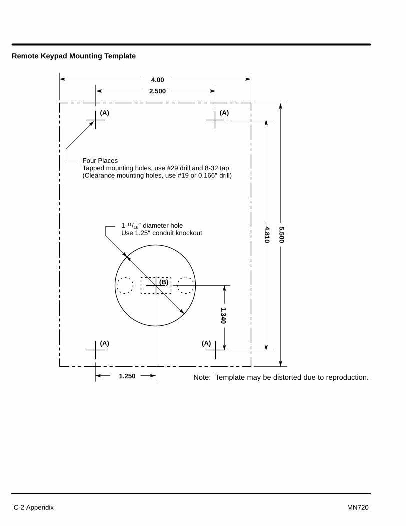
C-2 Appendix MN720
Remote Keypad Mounting Template
Four PlacesTapped mounting holes, use #29 drill and 8-32 tap(Clearance mounting holes, use #19 or 0.166″ drill)
4.00
2.500
1.250
1.340
4.810
5.500
1-11/16″ diameter holeUse 1.25″ conduit knockout
(B)
(A) (A)
(A) (A)
Note: Template may be distorted due to reproduction.

BALDOR ELECTRIC COMPANYP.O. Box 2400
Ft. Smith, AR 72902–2400(501) 646–4711
Fax (501) 648–5792
Baldor Electric CompanyMN720
Printed in USA1/01 C&J1500
CHTEL:+41 52 647 4700FAX:+41 52 659 2394
DTEL:+49 89 90 50 80FAX:+49 89 90 50 8491
UKTEL:+44 1454 850000FAX:+44 1454 850001
ITEL:+39 11 562 4440FAX:+39 11 562 5660
AUTEL:+61 29674 5455FAX:+61 29674 2495
FTEL:+33 145 10 7902FAX:+33 145 09 0864
CCTEL:+65 744 2572FAX:+65 747 1708
MXTEL:+52 47 61 2030FAX:+52 47 61 2010

��
��
��
���
��
��
� �
���
��
��
���
���
���
���
���
��
����


