Standard MNS Energy Range Rear Access Energy Centre 415V/6300 amps Introduction 3.3.0 Skillfully combining resources and expertise allows global technology leader ABB to manage a business interface with customers which brings successful results on a broad range of energy distribution projects. Within its extensive product portfolio, MNS is a compact low voltage switchgear solution with exceptional flexibility for energy distribution and motor control functions. It has been developed to encourage genuine profit and revenue gains for customers in many different sectors. Designed and built to form the centre of any modern power distribution system the new MNS-BS system offers unparalled levels of personnel safety, technical performance and operational reliability. The flexibility and intelligence applied to the design are apparent everywhere and at every level. The system is based upon a modular design incorporating tried and tested components selected from the wide range of ABB low voltage products. With the aid of sophisticated PC based tendering and engineering tools, as well as integrated design and production software, an entirely computerised flow of data from tendering through order processing, manufacturing and documentation and delivery is achieved. This ensures high and consistent quality and technical flexibility as well as short and on time deliveries to satisfy the most demanding needs for quick access to customised modern switchgear technology. ABB is the world’s leading manufacturer of electrotechnical equipment with global expertise and experience. Whether supplying an individual switchboard to a customer’s specific requirement or as part of a multi unit project package there will always be a local ABB branch able to provide comprehensive after sales service and support. Advice and assistance is offered for both Low Voltage Switchgear and Large Plant Engineering and will result in an efficient technical and cost effective solution for all requirements. NS and ABB will keep customers on top of electrotechnical developments today, tomorrow and for years to come.
Transcript
StandardMNS EnergyRange
Rear AccessEnergy Centre415V/6300 amps
Introduction 3.3.0
Skillfully combining resources and expertiseallows global technology leader ABB to manage a business interface with customerswhich brings successful results on a broadrange of energy distribution projects. Within itsextensive product portfolio, MNS is a compact low voltage switchgear solution withexceptional flexibility for energy distributionand motor control functions. It has beendeveloped to encourage genuine profit andrevenue gains for customers in many differentsectors.
Designed and built to form the centre of any modern power distribution system the new MNS-BS system offers unparalled levels of personnelsafety, technical performance and operational reliability.
The flexibility and intelligence applied to the design are apparent everywhere and at every level. The system is based upon a modulardesign incorporating tried and tested components selected from thewide range of ABB low voltage products.
With the aid of sophisticated PC based tendering and engineering tools,as well as integrated design and production software, an entirely computerised flow of data from tendering through order processing,manufacturing and documentation and delivery is achieved.
This ensures high and consistent quality and technical flexibility as wellas short and on time deliveries to satisfy the most demanding needs forquick access to customised modern switchgear technology.
ABB is the world’s leading manufacturer of electrotechnical equipmentwith global expertise and experience. Whether supplying an individual switchboard to a customer’s specific requirement or as part of a multi unitproject package there will always be a local ABB branch able to providecomprehensive after sales service and support.
Advice and assistance is offered for both Low Voltage Switchgear andLarge Plant Engineering and will result in an efficient technical and costeffective solution for all requirements.
NS and ABB will keep customers on top of electrotechnical developments today, tomorrow and for years to come.
Advantages of MNS
� Fully type tested in accordance with BS EN60439-1:1999 ASTA certified busbar systems up to 100kA for 1second
� Totally enclosed busbars and risers
� Main Busbar Ratings upto 6300Amps
� Distribution Busbars and Risers up to 4000A
� Rear cable access with devices removable from the front
� Separation in accordance with BS EN 60439-1:1999 up to Form 4b Type 7
� Framework and internal partitioning manufactured from galvanised sheet steel. Exterior cladding finished in electrostatic powder coated durable stove enamel Light Grey RAL7035 Texture
� Earthquake, vibration and shock proof design is largely maintenance free
� Easy conversion and retrofitting
StandardMNS EnergyRange
Rear AccessEnergy Centre415V/6300 amps
Features and Benefits 3.3.1
MNS Rear Access Low Voltage Switchboardsfrom ABB combine the experience of overthirty years of being at the forefront of technology in the design and manufacture oflow voltage switchgear solutions. Developedat the groups state of the art BS EN ISO9001 approved manufacturing facility basedin Sunderland, the new MNS Rear AccessSwitchboard offers to the discerning user a cost efficient product coupled with unparalled flexibility.
MNS is a complete switchgear system.Because the construction is based on welltested technology employing modular cubicles it is highly reliable and also the mostflexible and expandable system available.
Designed and built to form the centre of anymodern power distribution systemthe new MNSsystem offersunparalled levels ofpersonnel safety,technical performance andoperationalreliability. Whetheryou operate in thearea of pulp andpaper, metallurgy,petro-chemical,
power plants, offshore installations or in thedemanding infrastructure and building services sector you can be assured that withMNS we can provide a solution.
StandardMNS EnergyRange
Rear AccessEnergy Centre400V/6300 amps
Segregationand Wiring 3.3.6
Primary segregation within MNS is achieved through the division of the switchboard section into the three distinct zones of busbar, functionaland cabling. In simple terms the busbar zones contain the main anddistribution busbars; the functional zone houses the operational, incoming and outgoing devices; the cable zone segregates the cablesand wiring into an area which prevents the inevitable debris associatedwith these tasks coming into contact with the busbar and functionalareas during installation and maintenance.
Internal division is in the form of ventilated, galvanised sheet steel barriers providing a degree of protection conforming to IP 2X. Wherecables pass through plates then these are suitably harnessed and protected using grommets or insulated bushes. Cables between doorsand the fixed chassis are fully protected using flexible conduit or sleeving.
All internal control wiring is carried out in multi strand annealed copper conductors which is 600/1000volt grade PVC insulated with a minimumcross section of 1.0mm. Tri-rated cable complying with BS6231 is usedthroughout having a temperature rating of 105C. Wire ends are terminated with crimped connectors of the spade, ring or pin type, appropriate to the termination to which they are connected.
Segregation within the modern switchboardis of paramount importance. With demandfor operator safety increasing and device performance levels continually improving, thestructure which converts these devices into aworking system needs to combine optimumperformance with uncompromised levels ofsafety.
GENERAL
Outgoing cable connections
External Cableboxes to Form 4b Type 7
Click for animation GO
StandardMNS EnergyRange
Rear AccessEnergy Centre400V/6300 amps
Segregation and Wiring -continued
3.3.6a
Internal power wiring is carried out in tri-rated multi strand annealed copper conductors in accordance with BS6231. Insulation colour is blackthroughout with each cable end being clearly identified with phasecoloured tape or strapping. Cables are rated in accordance with the latest edition of the IEE wiring regulations and are provided with crimpedcable plugs of the appropriate size and type.
All cables are clearly identified using indelibly machine printed cable markers located at both ends of the cable.
Connection of functional units to outgoing cables is carried out in thecable zone in accordance with BS EN 60439-1:1999 Form 4B. Dependenton the application and project specification, additional levels of segrega-tion can be provided ranging from insulated bushes equipped with protec-tive shrouds (Form 4b type 5) up to individual fabricated steel cable boxesequipped with removable gland plates. (Form 4b type 7).
Cable boxes are sized to comply with the cable termination and spreadingrequirements contained in BS5398:1999. Terminations are once again, irre-spective of the trip setting or fuse rating sized to the maximum current orframe size of the device enabling circuits to be upgraded at a later datewith minimum disruption. Should oversize or parallel conductors be speci-fied provision will be made to accommodate these. As a consequencehowever the level of segregation achievable may be compromised.
Entry of incoming and outgoing cables can be from above or below or acombination of both. The space available for the termination of cableswithin the cable zone is extremely generous and allows ample room for thecable installation contractor to work unimpeded.
Irrespective of the trip setting or fuse rating all power wiring is sized to the maximum current or frame size of the appropriate device to ensure minimum disturbance should the circuit be upgradedat a later date.
Outgoing terminals withboot retainer
Flexible boots fitted toretainer Form 4b Type 5
StandardMNS EnergyRange
Rear AccessEnergy Centre400V/6300 amps
Outgoing Options 3.3.5
ABB is one of the world’s largest manufacturers of low voltage electrical components. Its comprehensive MNS-BS range includesair and moulded case circuit breakers, isolators and combinationswitches, motor starters, contactors and control devices and powerfactor correction equipment.
The flexible and modular design allows countless outgoing circuit device options tomeet the demands of wide ranging applications in diverse markets.
StandardMNS EnergyRange
Rear AccessEnergy Centre400V/6300 amps
Air Circuit Breakers 3.3.5a
Emax - E2 Emax - E3
The constant increase in the technological and functional complexity of electrical installations makes it essential for every component particularlythose such as protection circuit breakers which are crucial to safety tooffer the highest levels of continuity of service and reliability combinedwith minimal maintenance requirements.
ABB has designed the new generation of Emax low voltage air circuit breakers in line with these advanced installation requirements featuringhigh resistance to mechanical, electrical and thermal stresses.
Emax Air Circuit Breakers are designed to operate in conjunction withABB Isomax moulded case circuit breakers and have like them beendesigned for integration and accurate co-ordination with the many different low voltage products available from ABB.
Emax air circuit breakers are available in five different frame sizesE1,E2,E3, E4 and E6 all with the exception of E1 are available for incorporation in MNS. The current ratings and rated ultimate-short circuit breaking capacity of each frame size at 415volts are as follows:
� E2 up to 2000Amps 130kA
� E3 up to 3200Amps130kA
� E4 up to 4000Amps100kA
� E6 up to 6300Amps150kA
Air Circuit Breakers installed in MNS for outgoing circuits are selected from the ABB Emax range of technically advancedhigh performance Air Circuit Breakers complying fully with the requirements of BS EN 60947-2:1999 and IEC 60947-2:1999.
Emax Air Circuit Breaker - E4 Emax Air Circuit Breaker - E6
OUTGOING
StandardMNS EnergyRange
Rear AccessEnergy Centre400V/6300 amps
Air CircuitBreakers -continued
3.3.5b
Within MNS switchboards Emax air circuit breakers are mounted in individual cassettes fabricated from galvanised sheet steel with the frontcover being painted to match the exterior finish. Connections betweenthe ACB and the main or distribution busbars are carried out in single ormulti laminations of HDHC copper bar using purpose manufacturedconnector blocks at the termination points.
Outgoing cable access is provided at the rear of the ACB cassette andentry into the switchboard can be from above or below or a combination of both. Where a multi ACB installation is anticipated positioning the main horizontal busbars at the centre of the switchboard frequently results in a cost effective solution and simplifies the cableinstallation.
In the majority of installations ACBs are mounted in individual cubiclesto allow ample room for cabling and trunking.
Both dual and triple stacked ACB arrangements are available combiningE2 and E3 frame Air CircuitBreakers. However, in suchinstallations care must be exer-cised to ensure that adequatecabling capacity is available andthat the movement of cooling airthrough the structure is not com-promised.
Barriers are provided betweenthe busbar and outgoing side ofthe ACB connections ensuringfull compliance with the segregation requirements ofBSEN 60439-1:1999 Form 4.
A feature of the range is the modularity andthe fact that all breakers irrespective of rating have identical height and depthdimensions. Breakers are available in both triple and four pole configurations and for TPN applications a fixed neutral with detachable link, removable from the front of the switchboard is mounted alongside the breaker.
� E2 up to 2000Amps 130kA
� E3 up to 3200Amps 130kA
� E4 up to 4000Amps 100kA
� E6 up to 6300Amps 150kA
OUTGOING
Air Circuit Breaker Emax - E3
Dual stacked ACBs
Rear view of 6300A ACB connections tomain Busbars
StandardMNS EnergyRange
Rear AccessEnergy Centre400V/6300 amps
Moulded CaseCircuit Breakers -Outgoing
3.3.5c
The same criteria for the selection of air circuit breakers applies tomoulded case circuit breakers. It is again essential for every componentparticularly those crucial to safety to provide exceptional levels of reliability and minimal maintenance requirements.
These criteria were a vital aspect of the development of the Isomax Srange of MCCBs and resulted in a range of MCCBs of outstandingtechnical performance. Equipped with advanced state of the art electronic protection units, all are housed in enclosures with uniquelycompact dimensions.
Moulded Case Circuit Breakers employed inMNS are selected from the technicallyadvanced high performance Isomax S rangeand fully comply with International StandardsBS EN.60947-2:1999 and IEC 60947-2:1999.However for outgoing circuits, options areincreased with the addition of ABB’s revolutionary Tmax breaker with ratings from1 to 250Amps with both fixed and withdraw-able options. Tmax comes in three framesizes T1, T2 and T3 all of which are designedto operate and coordinate with each other.Selections of function and performance pre-viously unavailable in a breaker of this sizeare readily available and practically anyapplication up to 250Amps can be cateredfor within the three frame sizes.
Isomax - S5Isomax - S4
Tmax - T2 Tmax - T3
Isomax - S6 Isomax - S7
OUTGOING
StandardMNS EnergyRange
Rear AccessEnergy Centre400V/6300 amps
Moulded CaseCircuit Breakers -continued
3.3.5d
Breakers are mounted in individual, ventilated cassettes fabricated fromsmooth, galvanised sheet steel. Each cassette is fitted with a boltedcover or hinged door again depending on frame size through which theoperating handle protrudes. Both doors and covers are painted tomatch the switchboard’s exterior finish. Connections between mouldedcase circuit breakers and the main or distribution busbars are producedin single or multi laminations of electro-tinned HDHC copper bar.Purpose made connector blocks are used at the busbar juncture.Outgoing cable access is provided at the rear of the MCCB, with entryfrom above or below or a combination of both.
Dependent on frame size, breakers are available in MNS switchboards as fixed orwithdrawable units and can be supplied fullyprotected or as isolators. Both three and fourpole units are available in all frame sizes. ForTPN applications a fixed neutral with detachable link, removable from the front ofthe switchboard, is mounted alongside thebreaker.
OUTGOING
Rotary handle MCCBs
Outgoing rear connections fromMCCB with insulated Busbar plateremoved
4 Pole Tmax MCCBconnected to distribution barswith fully insulated terminals
� Tmax - T1 160A Thermal/Magnetic
� Tmax - T2 160A Electronic
� Tmax - T3 250A Thermal/Magnetic
� Isomax - S4 250A Electronic
� Isomax - S5 400A Electronic
� Isomax - S6 800A Electronic
� Isomax - S7 1250A Electronic
StandardMNS EnergyRange
Rear AccessEnergy Centre400V/6300 amps
MCCB BackpanAssemblies 3.3.5e
The installation of Moulded Case CircuitBreakers for outgoing circuits within MNS isfurther enhanced by the range of BackpanAssemblies available for group mounting ofMCCBs. Identical in all respects to the backpan so successful in the MNS range ofMCCB Panelboards this product allows forthe mounting of both single pole and multipole devices in an extremely compactand cost effective manner.
OUTGOING
Of particular interest to the Building Services and Retail market sectorswhere inclusion of single pole devices is frequently required, backpansare available in six, twelve or eighteen way triple pole units and can beprovided with a range of incoming protective devices or for direct connection. Segregation is achieved between devices by the use ofrigid mouldings and compliance up to BS EN 60439-1:1999 Form 4a.Type 5 is also available. The fully shrouded busbar system within the backpan utilises an innovative, patented design feature that encapsulates the busbars within insulated housings supported byextruded aluminium sections. These sections, designed to provide maximum strength and support, enable both conductors and devices tobe mounted in close proximity.
StandardMNS EnergyRange
Rear AccessEnergy Centre400V/6300 amps
MCCB BackpanAssemblies -continued
3.3.5f
Incoming and outgoing devices are selected from the ABB range ofhigh performance Isomax S and Tmax moulded case circuit breakers.
Within MNS MCCB backpans are mounted in individual, ventilated, galvanised sheet steel compartments supplied complete with a lockablehinged door which is finished in electrostatic, powder coated, durablestove enamel Light Grey to RAL7035 Texture.
Inside the compartment there are no exposed parts and the complete backpan is fully shrouded to prevent accidental contact.
Connection between the main or distribution busbar and the backpanare carried out in single or multi laminations of electro-tinned HDHCcopper bar using purpose manufactured connector blocks at the busbar juncture.
Outgoing cable access is provided at the rear of the backpan and entryinto the switchboard can be from above or below or a combination ofboth.
ASTA certified in accordance with BS EN60439-1:1999 to withstand a through fault of50kA for 1 second the one piece 800Ampbusbar system has no joints and is specifically designed to prevent theoccurence of hot spots. The aluminium busbar support provides an effective medium for the dissipation of heat in highambient temperatures.
� Tmax - T1 1P 160A Thermal/Magnetic
� Tmax - T1 160A Thermal/Magnetic
� Tmax - T2 160A Electronic
� Tmax - T3 250A Thermal/Magnetic
OUTGOING
StandardMNS EnergyRange
Rear AccessEnergy Centre400V/6300 amps
CombinationSwitchfuses and Isolators
3.3.5g
The fuse links are mechanically stationary elements, ensuring a long electrical and mechanical life for both AC and DC network applications. The units are of extremely compact dimensions allowing the construction of cost effective compact switchboards.
Powerline switchfuses are available in single to four pole configurations and can be specified with either switched orbolted neutrals with detachable neutral links.
In the case of switched neutral versions the contacts can be arranged for either simultaneous or early make/late breakswitching.
The design and manufacture of fusetechnology employ the latest technology inthe design and manufacture of fuse technology and have been fullytested in accordance with IEC947-3. Among the many advanced operational and safety features the following are included:
� Fuse carriers fully IP20 protected
� Fully protected fuse housings
� Patented operator independent quick make/quick break contacts which are self cleaning
� Wide selection of auxiliary contacts
� Flexible mounting
� Choice of operators
Within MNS switchfuses are located in individual, ventilated, galvanisedsheet steel compartments complete with hinged door which is paintedLight grey RAL7035 Texture to match the exterior finish of the switchboard. A rotary door interlocked operating handle is providedwhich can be locked in the OFF position.
Connections between switchfuses and the main or distribution busbarsare carried out in single or multi laminations of electro-tinned HDHCcopper bar using purpose manufactured connector blocks at the busbar juncture.
Incoming cable access is provided at the rear of the switchfuse compartment and entry into the switchboard can be from above orbelow or a combination of both.
Switchfuses incorporated in MNS are selected from the ABB Powerline range of combination switches with ratings rangingfrom 125Amps to 800Amps. The Powerlineswitchfuse combines a fused short circuitprotection device with load break switchingon both sides of the fusible element.
� Powerline OS Switchfuses 125A - 200A
� Powerline OESA Switchfuses 400A - 800A
� Slimline SRM Plug-in Switchfuses 63A - 630A
OUTGOING
Slimline Switchfuse with outgoing cables
StandardMNS EnergyRange
Rear AccessEnergy Centre400V/6300 amps
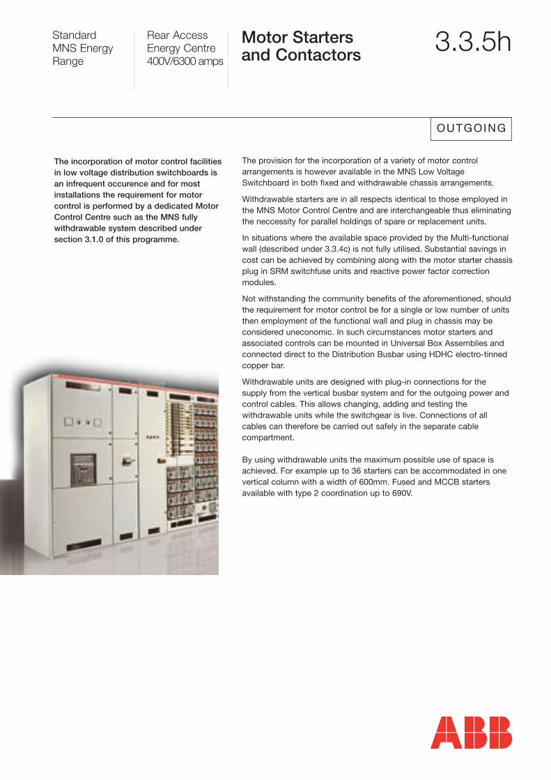
Motor Startersand Contactors 3.3.5h
OUTGOING
The provision for the incorporation of a variety of motor control arrangements is however available in the MNS Low VoltageSwitchboard in both fixed and withdrawable chassis arrangements.
Withdrawable starters are in all respects identical to those employed inthe MNS Motor Control Centre and are interchangeable thus eliminatingthe neccessity for parallel holdings of spare or replacement units.
In situations where the available space provided by the Multi-functionalwall (described under 3.3.4c) is not fully utilised. Substantial savings incost can be achieved by combining along with the motor starter chassisplug in SRM switchfuse units and reactive power factor correction modules.
Not withstanding the community benefits of the aforementioned, shouldthe requirement for motor control be for a single or low number of unitsthen employment of the functional wall and plug in chassis may be considered uneconomic. In such circumstances motor starters andassociated controls can be mounted in Universal Box Assemblies andconnected direct to the Distribution Busbar using HDHC electro-tinnedcopper bar.
Withdrawable units are designed with plug-in connections for the supply from the vertical busbar system and for the outgoing power andcontrol cables. This allows changing, adding and testing the withdrawable units while the switchgear is live. Connections of allcables can therefore be carried out safely in the separate cable compartment.
By using withdrawable units the maximum possible use of space isachieved. For example up to 36 starters can be accommodated in onevertical column with a width of 600mm. Fused and MCCB starters available with type 2 coordination up to 690V.
The incorporation of motor control facilitiesin low voltage distribution switchboards isan infrequent occurence and for most installations the requirement for motor control is performed by a dedicated MotorControl Centre such as the MNS fully withdrawable system described under section 3.1.0 of this programme.
The instrument panel has preformed knockouts for mounting, measuring, operating and indicating instruments.
The main switchgear (normally a fused motor switch or circuit-breaker)is operated by means of the operating handle located at the instrumentpanel, which is also used for the electrical as well as the mechanicalinterlocking function. A micro-switch with 1 make and 1 break contactis provided for electrical interlocking.
The withdrawable module condaptor is designed for a current up to 125A and can hold 2 modules size 8E/2 up to 63A or 4 modules size8E/4 up to 45A.
It comprises a 20-pole control connector for each module size 8E/4 and one or two 20-pole control connectors for each module size 8E/2.
The connections between the incoming and outgoing side are arrangedinside the withdrawable module condaptor and are protected against accidental arcs.
Withdrawable modules size 8E/4 and 8E/2.
These modules consist of the instrumentpanel and side panels made of insulatingmaterial, the rear wall with integrated cableconnections, and a 20-pole control connector as well as one or two profile sections for mounting snap-mounted components. If required the withdrawablemodule size 8/E2 can be equipped with 2 x 20 pole control connectors.
StandardMNS EnergyRange
Rear AccessEnergy Centre400V/6300 amps
Motor Startersand Contactors -continued
3.3.5i
OUTGOING
StandardMNS EnergyRange
Rear AccessEnergy Centre400V/6300 amps
Motor Startersand Contactors -continued
3.3.5j
OUTGOING
Withdrawable module condapter forfast expansion and modification of anenergised switchgear cubicle with small withdrawable modules size 8E/4 and 8E/2.
Motor Starters up to 315kW - Feeders up to800A. Withdrawable modules size 4E, 8E,12E, 16E, 20E, 24E, 36E and 40E.
The withdrawable modules consist of aninstrument panel and a rear wall made ofinsulating material and a front cover and sidepanels made of sheet steel as well as mount-ing channels. The hinged front cover offersthe advantage of easy accessibility of the built-in components (eg. for replacingfuses) from the front without withdrawing the module.
The front cover incorporates a cut out sectionfor an instrument panel which remains in position when the cover is opened. It is alsodesigned with preformed knockouts formounting instruments.
The front cover incorporates a cut out section for an instrument panel which remains in position when the cover is opened. It is also designedwith preformed knockouts for mounting instruments.
Module size 16E (with compartmentdoor) up to 132kW. Maximum 4in cubicle.
Module size 24E (with compartmentdoor) up to 250kW. Maximum 3in cubicle.
MNS - Main PowerContact
StandardMNS EnergyRange
Rear AccessEnergy Centre400V/6300 amps
Power FactorCorrection 3.3.5k
ABB has for many years been the market leader in dry type power factor correction capacitor technology. In that time the company’s reputation has grown worldwide for producing capacitors offering:
� Long life even under electrical stress
� Peak current handling capacity
� Minimum dielectric losses
� An integrated approach to facility and personnel safety consisting of self healing capacitor elements contained in avermiculite filled container complete with internal protection for the elements.
The practise of incorporating Power Factor Correction equipment into distribution switchboards has become commonplace in the last decadeand the solution provided within MNS offers levels of flexibility andcompactness hitherto unachievable. Among these benefits are the following.
� Cost savings by integration of the compensation modules into the switchgear system
� Compact size by combining the compensation modules with withdrawable distribution feeders and motor starters on a common functional wall riser
� Protection against accidental contact with the live distribution busbars provided by fully shrouded plug and socket shrouds
� High operational reliability and personal safety through internal arc partitioning between equipment compartment and busbar compartment
On installations where harmonics are present caused by non-linearelectrical loads such as variable speed drives, rectifiers, UPS systemsand computer reactors can be provided. These are mounted alongsidethe capacitors and form part of the withdrawable PFC chassis.
Control and switching of the PFC stages is performed by an ABB TypeRVC or RVK relays selection of which is dependent on the application. In addition to the controlling function relays are provided with monitoring and measurement functions and communication facilities.
GENERAL
In addition to the comprehensive range of modules which housedevices such as moulded case circuit breakers and switchfuses, acomprehensive range of universal box assemblies complete the MNSsystem and is available for the mounting of:
� MCB distribution boards
� instrumentation and meters
� contactors and relays
� fixed pattern motor starters
� control equipment
Each Universal Box assembly includes a hinged door and internalmounting plate the position of which is adjustable at 50mm intervals toa maximum depth of 310mm. All internal box components are manufactured from smooth, galvanised sheet steel. Doors are equippedwith concealed lift off hinges and can be supplied, drilled or punched toaccommodate door mounted equipment such as meters and relays.Exterior finish is durable electro statically applied powder coated paintLight Grey RAL7035 texture. Alternative finishes are available to orderat additional cost.
On Universal Boxes up to 600mm wide by 1000mm high (40E) a singledoor is provided which can be hinged on either side. Above this sizeUniversal Boxes are provided with double doors.
StandardMNS EnergyRange
Rear AccessEnergy Centre400V/6300 amps
Universal BoxAssemblies 3.3.5l
GENERAL
StandardMNS EnergyRange
Rear AccessEnergy Centre400V/6300 amps
Busbar System 3.3.4
In developing the MNS range ABB designers were aware that an innovative busbar design was necessary to account for the stressesimposed by ever increasing energy levels being distributed at low voltage while simultaneously providing the flexibility to allow devices tobe easily added or removed. A compact solution enabling the maximumnumber of circuits to be incorporated was also vital in view of therestrictions imposed by architects and specifiers. In the new MNS rangethe busbar system meets all the above criteria. Independent tests byASTA in accordance with BSEN 60439-1: 1999 achieved up to 100kAfor 1 second on main busbars and up to 80kA for 1 second on distribution busbars and risers.
While accepting the importance of the structure and functions carried out by theincoming and outgoing devices, the busbarsystem could justifiably be considered themost important element of the modern dayswitchboard. Both the incoming power delivering devices and the outgoing deviceswhich control and distribute the energy areconnected to it.
Cast copper connection on main Busbarsto distribution bars
StandardMNS EnergyRange
Rear AccessEnergy Centre400V/6300 amps
Main HorizontalBusbars System 3.3.4a
The main busbar support structure compris-es high density, modular glass reinforced polyester mouldings surrounded by a rigidstainless steel frame.
The whole busbar assembly can be located at the top, centre or bottomof the switchboard to provide flexibility in the mounting of incoming and outgoing devices and to aid the entry of incoming and outgoing cables.Irrespective of location the busbar system is extendible at either end ofthe switchboard.
Main busbars are manufactured from electro tinned, rectangular section, hard drawn, high conductivity copper bar. For current ratingsup to and including 4000Amps, two laminations of copper bar are usedfor both phase and neutral conductors. For 5000 and 6300 Amp assemblies, four laminations arranged in a packetised formation formaximum current carrying efficiency are used for both phase and neutral. Ratings up to 10000Amps are available to order. For systemswith high harmonic content the neutral conductor can be supplied attwice the rating of the phase conductors.
4000A main Busbars
StandardMNS EnergyRange
Rear AccessEnergy Centre400V/6300 amps
Main HorizontalBusbars System -continued
3.3.4b
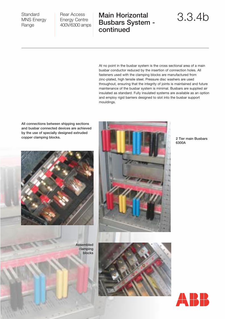
All connections between shipping sectionsand busbar connected devices are achievedby the use of specially designed extrudedcopper clamping blocks.
At no point in the busbar system is the cross sectional area of a mainbusbar conductor reduced by the insertion of connection holes. All fasteners used with the clamping blocks are manufactured from zinc-plated, high tensile steel. Pressure disc washers are used throughout, ensuring that the integrity of joints is maintained and future maintenance of the busbar system is minimal. Busbars are supplied airinsulated as standard. Fully insulated systems are available as an optionand employ rigid barriers designed to slot into the busbar supportmouldings.
2 Tier main Busbars6300A
Assembledclamping
blocks
StandardMNS EnergyRange
Rear AccessEnergy Centre400V/6300 amps
Distribution Busbarsand Risers 3.3.4c
Available in 2000Amp and 4000Amp ratings,distribution busbars and risers are manufactured from specially developedextruded sections of hard drawn, high conductivity copper or aluminium. The cop-per extrusion is electro-tinned and the alu-minium alochromed to eliminate the possibil-ity of any chemical interaction when con-necting with dissimilar metals.
TP&N MCCB connected to distribution bars
Distribution bars
Distribution busbars and risers are located in a ventilated sheet steelchamber and are held in place by high density glass reinforced mouldings with securing bolts locking the mountings together. Connection between the main busbar system and the distribution busbar riser is achieved by the use of a purpose designed copper casting of immense strength profiled to lock onto the main busbar providing a highly secure connection. The profile allows the connectionof devices to each side of the riser enabling a high number of devicesto be installed in a relatively small space. Connections between the distribution busbar and devices is by electro-tinned, hard drawn, highconductivity copper bar. Attachment of the device connections to thedistribution busbar uses specially designed non-rotating cast bolts fitted with pressure disc washers.
StandardMNS EnergyRange
Rear AccessEnergy Centre400V/6300 amps
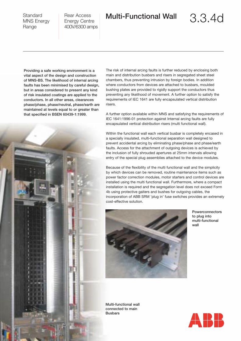
Multi-Functional Wall 3.3.4d
Providing a safe working environment is avital aspect of the design and constructionof MNS-BS. The likelihood of internal arcingfaults has been minimised by careful design,but in areas considered to present any kindof risk insulated coatings are applied to the conductors. In all other areas, clearancesphase/phase, phase/neutral, phase/earth aremaintained at levels equal to or greater thanthat specified in BSEN 60439-1:1999.
The risk of internal arcing faults is further reduced by enclosing bothmain and distribution busbars and risers in segregated sheet steelchambers, thus preventing intrusion by foreign bodies. In additionwhere conductors from devices are attached to busbars, mouldedbushing plates are provided to rigidly support the conductors thus preventing any likelihood of movement. A further option to satisfy therequirements of IEC 1641 are fully encapsulated vertical distribution risers.
A further option available within MNS and satisfying the requirements ofIEC 1641:1996-01 protection against Internal arcing faults are fullyencapsulated vertical distribution risers (multi functional wall).
Within the functional wall each vertical busbar is completely encased ina specially insulated, multi-functional separation wall designed to prevent accidental arcing by eliminating phase/phase and phase/earthfaults. Access for the attachment of outgoing devices is achieved bythe inclusion of fully shrouded apertures at 25mm intervals allowingentry of the special plug assemblies attached to the device modules.
Because of the flexibility of the multi functional wall and the simplicityby which devices can be removed, routine maintenance items such aspower factor correction modules, motor starters and control devices areinstalled using the multi functional wall. Furthermore, where a compact installation is required and the segregation level does not exceed Form4b using protective gaiters and bushes for outgoing cables, the incorporation of ABB SRM ’plug in’ fuse switches provides an extremelycost-effective solution.
Powerconnectorsto plug into multi-functionalwall
Multi-functional wallconnected to mainBusbars
StandardMNS EnergyRange
Rear AccessEnergy Centre400V/6300 amps
Incoming Arrangements 3.3.3
The flexibility of MNS-BS permits endlesscombinations of incoming arrangements tobe accommodated, provides ample space forincoming cables and where applicable, bustrunking. It also maximises performance andensures many years of trouble-free performance with the minimum of maintenance.
Incoming devices are selected from the comprehensive range of lowvoltage devices manufactured by ABB all of which can be guaranteedto provide high levels of performance with long lasting capability. Testedindependently in accordance with international specifications, the fullrange of devices can be relied upon to provide superior performanceand unprecedented levels of operator and system safety.
Available in the list of incoming options are the following:ACBs up to 6300AmpsMCCBs up to 2000AmpsFuse Switches up to 800AmpsIsolators up to 3150AmpsDirect Cable Bus Trunking
Fuseswitch
Tmax MCCB
Emax Air Circuit Breaker
StandardMNS EnergyRange
Rear AccessEnergy Centre400V/6300 amps
Air Circuit Breakers 3.3.3a
Air Circuit Breakers installed in MNS-BS arefrom the ABB Emax range. A technicallyadvanced high performance range complyingfully with the requirements of BS EN 60947-2:1999 and IEC 60947-2:1999.
The constant increase in the technological and functional complexity ofelectrical installations makes it essential for every component particularly those crucial to safety to provide exceptional levels of reliability and minimal maintenance requirements.
ABB has created the new generation of Emax low voltage air circuitbreakers to fully comply with these advanced installation requirements.Featuring high resistance to mechanical, electrical and thermal stressesthey operate perfectly with ABB Isomax moulded case circuit breakersand will integrate and co-ordinate with the many different low voltageproducts available from ABB.
Emax air circuit breakers are available in five different frame sizesE1,E2,E3, E4 and E6. All with the exception of E1 are available forincorporation in MNS. The current ratings and rated ultimate short circuit breaking capacity of each frame size at 415 volts are as follows:
� E2 up to 2000Amps 130kA
� E3 up to 3200Amps 130kA
� E4 up to 4000Amps 100kA
� E6 up to 6300Amps 150kA
Emax - E2 Emax - E3 Emax Air Circuit Breaker - E4 Emax Air Circuit Breaker - E6
StandardMNS EnergyRange
Rear AccessEnergy Centre400V/6300 amps
Air CircuitBreakers - continued 3.3.3b
A feature of the range is the modularity created by the fact that all breakers, irrespective of rating have identical heightand depth dimensions. Breakers are avail-able in either triple or four pole configura-tions, while for TPN applications a fixed neu-tral with detachable link removable from thefront of the switchboard is mounted along-side the breaker.
Emax air circuit breakers are mounted within MNS-BS in galvanisedsteel cassettes painted to match the exterior finish. Connectionsbetween the ACB and the main or distribution busbars are carried out insingle or multi laminations of hard drawn high conductivity copper barusing purpose manufactured connector blocks at the termination points.
Incoming cable access is provided at the rear of the cassette with entryinto the switchboard from above, below or a combination of both. In thecase of a multi ACB installation the main horizontal busbars are posi-tioned at the centre of the switchboard for cost effectiveness and instal-lation simplification.
In most installations ACBs are mounted in separate cubicles to allowroom for cabling, trunking and the frequently required metering and protection devices. Current transformers are provided on incoming busbars for protection and metering purposes.
Barriers are provided between the incoming and busbar side of the ACBconnections to comply with the segregation requirements of BSEN60439-1:1999 Form 4. When used as bus couplers both sides of theACB are totally segregated. Using barriers as previously described andby utilising bus transition sections, segregation between each busbar isachieved.
Both dual and triple stacked ACB arrangements are available combiningE2 and E3 frame breakers. In such installations however care must beexercised to ensure that adequate cabling capacity is available and thatthe movement of cooling air through the structure is not compromised.
� E2 up to 2000Amps 130kA
� E3 up to 3200Amps 130kA
� E4 up to 4000Amps 100kA
� E6 up to 6300Amps 150kA
Cable connections toincoming or outgoing ACBCopperwork
ACB housed in A ‘Cassette’showing removable neutral link
2 Tier main Busbars showing copperwork connections to ACB
StandardMNS EnergyRange
Rear AccessEnergy Centre400V/6300 amps
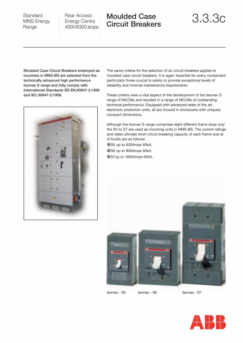
Moulded Case Circuit Breakers 3.3.3c
The same criteria for the selection of air circuit breakers applies tomoulded case circuit breakers. It is again essential for every componentparticularly those crucial to safety to provide exceptional levels of reliability and minimal maintenance requirements.
These criteria were a vital aspect of the development of the Isomax Srange of MCCBs and resulted in a range of MCCBs of outstandingtechnical performance. Equipped with advanced state of the art electronic protection units, all are housed in enclosures with uniquelycompact dimensions.
Although the Isomax S range comprises eight different frame sizes onlythe S5 to S7 are used as incoming units in MNS-BS. The current ratingsand rated ultimate short circuit breaking capacity of each frame size at415volts are as follows:
�S5 up to 630Amps 65kA.
�S6 up to 800Amps 65kA.
�S7up to 1600Amps 65kA.
Isomax - S5 Isomax - S6 Isomax - S7
Moulded Case Circuit Breakers employed asincomers in MNS-BS are selected from thetechnically advanced high performanceIsomax S range and fully comply withInternational Standards BS EN.60947-2:1999and IEC 60947-2:1999.
StandardMNS EnergyRange
Rear AccessEnergy Centre400V/6300 amps
Moulded Case Circuit Breakers - continued
3.3.3d
Dependent on frame size, breakers are available in MNS switchboardsas fixed or withdrawable units and can be supplied fully protected or asisolators. Both three and four pole units are available in all frame sizes.For TPN applications a fixed neutral with detachable link removablefrom the front of the switchboard, is mounted alongside the breaker.Breakers are mounted in individual, ventilated cassettes fabricated fromsmooth, galvanised sheet steel. Each cassette is fitted with a boltedcover or hinged door again depending on frame size through which theoperator protrudes. Both doors and covers are painted to match theswitchboard’s exterior finish. Connections between moulded case circuit breakers and the main or distribution busbars are produced insingle or multi laminations of electro-tinned HDHC copper bar. Purposemade connector blocks are used at the busbar juncture. Outgoing cableaccess is provided at the rear of the MCCB, with entry from above orbelow or a combination of both.
Incoming cable access is provided at the rear of the MCCB compartment and entry into the switchboard can be from above orbelow or a combination of both.
� S5 up to 630Amps 65kA
� S6 up to 800Amps 65kA
� S7 up to 1600Amps 65kA
MCCB in cassette mounted in switchboard
4 Pole Tmax MCCB connected to distribution bars with fully insulated terminals
StandardMNS EnergyRange
Rear AccessEnergy Centre400V/6300 amps
SwitchfuseIncomer 3.3.3e
Powerline switchfuses are available in one to four pole configurationsand can be specified with either switched or bolted neutrals withdetachable neutral links. In the case of switched neutral versions thecontacts can be arranged either simultaneously or early make/latebreak switching. The design of Powerline switchfuses incorporates thelatest techniques in thedesign and manufactureof fuse technology andhave been fully tested inaccordance withIEC947-3. Includedamong the manyadvanced operationaland safety features arethe following:
● Current Ratings 400 to 800Amps, 3 and 4 Pole● Fully IP20 protected fuse carriers● Fully protected fuse housings● Patented operator independent quick make/quick break self cleaning
contacts ● Wide choice of auxiliary contacts● Flexible mounting● Choice of operators
Within MNS-BS, switchfuses are located in individual, ventilated, galvanised sheet steel compartments complete with a hinged doorpainted to match the exterior finish of the switchboard. (light greyRAL7035 texture)
A lockable rotary door operating handle is provided which can belocked in the OFF position. Connections between switchfuses and themain or distribution busbars are produced in single or multi laminationsof electro-tinned HDHC copper bar. Purpose manufactured connectorblocks are used at the busbar juncture. Incoming cable access is provided at the rear of the switchfuse compartment and entry into theswitchboard can be from above, below or a combination of both.
Switchfuses used in MNS-BS are selectedfrom the ABB Powerline range of combination switches. Ratings range from20Amps to 800Amps. The Powerline switchfuse combines a fused short circuitprotection device with load break switch-ing on both sides of the fusible element.The fuse links are mechanically stationary elements, ensuring a long electrical andmechanical life for both AC and DC net-work applications. Extremely compact unitdimensions allow the construction of costeffective compact switchboards.
OESA Combination Switchfuses
40A Fuseswitch connected to distributionbars with fully insulated terminals
StandardMNS EnergyRange
Rear AccessEnergy Centre400V/6300 amps
Cubicle Construction& Mechanical Design 3.3.2
The construction of MNS is built around anextremely rigid bolted framework of rollformed ‘C’ section profiles manufacturedfrom 2mm galvanised mild steel. Each framemember is equipped with pre-punched holesat 25mm intervals for the mounting ofdevices, doors and covers. Each switchboard frame is assembled utilising unique mechanical corner joints andtransverse top and bottom beams resultingin the production of a cubicle of immensestrength and rigidity.
Complete cubicles are then bolted onto galvanised steel plinths whichrun the full length of the assembled shipping sections further adding tothe rigidity of the structure. Rectangular apertures are positioned in thefront and rear of the plinth to facilitate movement of the switchboardsections during installation.
Once installed grilles are clipped into the apertures allowing cool air toenter the switchboard at low level, passing through the switchboardbefore exiting at the top through carefully positioned roof vents.
The cooling is achieved by the chimney effect due to the careful positioning of airways and ventilation plates. Temperature rise testshave proven that devices installed in MNS are capable of achievingoperational performance equal to that achieved in free air.
All internal device compartments, barriers and partitions are manufactured from smooth finish galvanised sheet steel ventilated toallow the free flow of air throughout the structure while at the same timebeing strategically placed to prevent the passage of ionised gas flowingbetween device compartments in the unlikely event of an internal arcingfault developing. The modular construction of MNS proves of immense benefit when last minute alterations are required during the constructionstage or, when after a period in service operational requirementschange. The unique structure with fixing provisions at 25mm intervalson all planes allows removal and additions to be carried out with theminimum of effort.
This feature coupled with the flexible distribution busbar riser unique to MNS allows modifications to be carried out quickly and with minimum disruption. Exterior covers, doors and cladding panels are manufactured from smooth galvanised steel as used for all other MNS components. As an additional protection and to enhance aestheticsexterior surfaces are finished in electrostatic powder coated durablestove enamel Light Grey to RAL7035 Texture. Other finishes are available to special order and at additional cost.
With regard to segregation and degree of protection MNS is supplied asstandard to meet the requirements of IP2x for internal and IP42 forexternal segregation. Enhanced ratings are available to special order.
Click for animation GO
StandardMNS EnergyRange
Rear AccessEnergy Centre400V/6300 amps
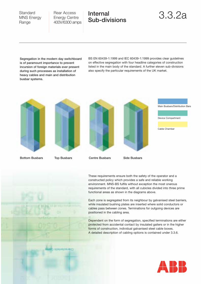
3.3.2aInternal Sub-divisions
Segregation in the modern day switchboardis of paramount importance to prevent incursion of foreign materials ever presentduring such processes as installation ofheavy cables and main and distribution busbar systems.
BS EN 60439-1:1999 and IEC 60439-1:1999 provides clear guidelineson effective segregation with four headline categories of constructionlisted in the main body of the standard. A further eleven sub-divisionsalso specify the particular requirements of the UK market.
These requirements ensure both the safety of the operator and a constructed policy which provides a safe and reliable working environment. MNS-BS fulfils without exception the most onerousrequirements of the standard, with all cubicles divided into three primefunctional areas as shown in the diagrams above.
Each zone is segregated from its neighbour by galvanised steel barriers,while insulated bushing plates are inserted where solid conductors orcables pass between zones. Terminations for outgoing devices arepositioned in the cabling area.
Dependent on the form of segregation, specified terminations are eitherprotected from accidental contact by insulated gaiters or in the higherforms of construction, individual galvanised steel cable boxes. A detailed description of cabling options is contained under 3.3.6.
Bottom Busbars Top Busbars Centre Busbars Side Busbars


![Large Aperture [O I] 6300A Photometry of Comet Hale-Bopp](https://static.documents.pub/doc/80x56/6206410c8c2f7b173005e7e8/large-aperture-o-i-6300a-photometry-of-comet-hale-bopp.jpg)


