38
MNS iS Motor Control Center MControl Interface Manual Profibus Direct System Release V5.4/0
MNS iS Motor Control Center MControl Interface Manual Profibus Direct System Release V5.4/0

MNS is a registered trademark.
Emax, Tmax are registered trademarks of ABB SACE Spa.
Microsoft, Windows and Windows XP are registered trademarks of Microsoft Corporation.
JAVA is a registered trademark from Sun Microsystems.
Product names of other products are registered trademarks of their manufacturers or owners.
This document relates to the MNS iS System Release 5.4/0.
The information in this document is subject to change without notice and should not be construed as a commitment by ABB. ABB assumes no responsibility for any errors that may appear in this document.
In no event shall ABB be liable for direct, indirect, special, incidental, or consequential damages of any nature or kind arising from the use of this document, nor shall ABB be liable for incidental or consequential damages arising from use of any software or hardware described in this document.
This document and parts thereof must not be reproduced or copied without ABB's written permission, and the contents thereof must not be imparted to a third party nor be used for any unauthorized purpose. The software described in this document is furnished under a license and may be used, copied, or disclosed only in accordance with the terms of such license.
All rights reserved.
Copyright © 2009 ABB Automation Products GmbH, Ladenburg, Germany
MNS iS MControl Interface Manual Profibus Direct
Content
1TGC910187M0201 – Release V5.4 3
Table of content
General ........................................................................................................................... 4 Target Group ..........................................................................................................................................4 Use of Warning, Caution, Information and Tip icon ...............................................................................4 Terminology............................................................................................................................................5 Related Documentation..........................................................................................................................9 Related System Version.........................................................................................................................9 Document Revision History....................................................................................................................9
Introduction.................................................................................................................. 10 Profibus Standard.................................................................................................................................10 MNS iS Hardware Requirements .........................................................................................................10 MNS iS Software Requirements ..........................................................................................................10
Basics........................................................................................................................... 11 PROFIBUS DP-V0 ...............................................................................................................................11
Cyclic Data Communication..........................................................................................................11 Diagnostics....................................................................................................................................11
PROFIBUS DP-V1 ...............................................................................................................................13 Acyclic Data Communication ........................................................................................................13
Interfaces...................................................................................................................... 14 MControl Profibus connector................................................................................................................14 Connection ...........................................................................................................................................14 Termination ..........................................................................................................................................15
Getting Started............................................................................................................. 17 Configuration parameters.....................................................................................................................17 Parameters...........................................................................................................................................17 Addressing ...........................................................................................................................................18 Failsafe.................................................................................................................................................19 Control Access .....................................................................................................................................20
PROFIBUS Data Mapping............................................................................................ 21 General.................................................................................................................................................21 Monitoring data.....................................................................................................................................22 QualityCode..........................................................................................................................................28 MControl status ....................................................................................................................................31 Starter dependent information..............................................................................................................32 Command format..................................................................................................................................33
General MNS iS MControl Interface ManualProfibus Direct
4 1TGC910187M0201 – Release V5.4
General
Target Group This document describes communication and control interfaces used in MNS iS.
The manual is primarily intended for those requiring information on accessing information and data provided from MNS iS. Furthermore the document provides information for integration of MNS iS as fieldbus component into PLC or higher level Process Control Systems to control system and application engineers.
It is assumed that the reader of this manual is familiar with basic terms of fieldbus and control communication (e.g. basic knowledge about PROFIBUS, Modbus etc.).
Use of Warning, Caution, Information and Tip icon

MNS iS MControl Interface Manual Profibus Direct
General
1TGC910187M0201 – Release V5.4 5
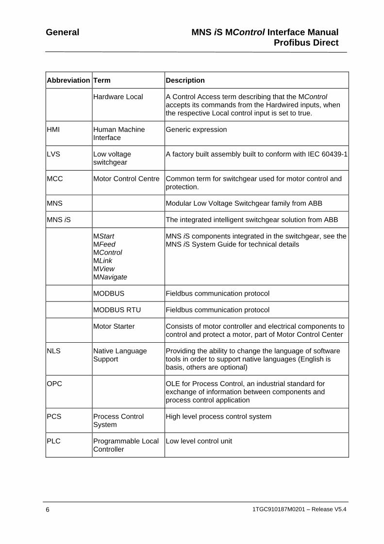
Terminology List of the terms, acronyms, abbreviations and definitions that the document uses.
Abbreviation Term Description
Aspect Object ABB technology. An Aspect Object is a computer representation of a real object such as a pump, a valve, an order or a virtual object such as a service or an object type. An Aspect Object is described by its aspects and is organized in structures.
Alarm Alarm is defined as status transition from any state to abnormal state. Status transition to abnormal state can be data crossing over the pre-defined alarm limit.
Bus Local A Control Access term describing that the MControl accepts its commands from a device on the switchgear control network, e.g. the Web Interface, MView.
COTS Commercial off the shelf
Commercial off the shelf product, term to describe products available on the market, ready to use
DCS Distributed Control System
See also PCS
DTM Device Type Manager Software module used to manage devices via fieldbus (e.g. PROFIBUS) using frame application environment (e.g. PactWare, ABB Fieldbus Builder etc.)
Eth. Ethernet Ethernet is a local area network (LAN) technology. The Ethernet standard specifies the physical medium, access control rules and the message frames.
Event An event is a status transition from one state to another. It can be defined as alarm, if the state is defined as abnormal or as warning as a pre-alarm state.
FD Field Device Term for devices connected to the fieldbus (e.g. motor control units or circuit breaker protection)
GSD file Geräte Stamm Datei (German abbreviation)
A hardware description file for a PROFIBUS-DP or PROFIBUS-DP/V1 slave type
GPS Global Positioning System
System to detect local position, universal time and time zone, GPS technology provides accurate time to a system
General MNS iS MControl Interface ManualProfibus Direct
6 1TGC910187M0201 – Release V5.4
Abbreviation Term Description
Hardware Local A Control Access term describing that the MControl accepts its commands from the Hardwired inputs, when the respective Local control input is set to true.
HMI Human Machine Interface
Generic expression
LVS Low voltage switchgear
A factory built assembly built to conform with IEC 60439-1
MCC Motor Control Centre Common term for switchgear used for motor control and protection.
MNS Modular Low Voltage Switchgear family from ABB
MNS iS The integrated intelligent switchgear solution from ABB
MStart MFeed MControl MLink MView MNavigate
MNS iS components integrated in the switchgear, see the MNS iS System Guide for technical details
MODBUS Fieldbus communication protocol
MODBUS RTU Fieldbus communication protocol
Motor Starter Consists of motor controller and electrical components to control and protect a motor, part of Motor Control Center
NLS Native Language Support
Providing the ability to change the language of software tools in order to support native languages (English is basis, others are optional)
OPC OLE for Process Control, an industrial standard for exchange of information between components and process control application
PCS Process Control System
High level process control system
PLC Programmable Local Controller
Low level control unit

MNS iS MControl Interface Manual Profibus Direct
General
1TGC910187M0201 – Release V5.4 7
Abbreviation Term Description
PROFIBUS-DP Fieldbus communication protocol with cyclic data transfer (V0).
PROFIBUS-DP/V1 Fieldbus communication protocol, extension of PROFIBUS- DP allowing acyclic data transfer and multi master (V1).
PROFIBUS-DP/V2 Fieldbus communication protocol, extension of PROFIBUS- DP allowing time stamp and communication between master and slave (V2).
RCU Remote Control Unit Local control unit with pushbutton and indicator to operate a device (e.g. motor) from field level.
RS232 Standard No. 232 for PC communication, established by EIA (Electronics Industries Association, USA)
RS485 Communication interface standard from EIA (Electronics Industries Association, USA), operating on voltages between 0V and +5V. RS-485 is more noise resistant than RS-232C, handles data transmission over longer distances, and can drive more receivers.
RTC Real Time Clock Integrated clock function in devices used to generate time and date information if a remote clock system is not present
Software Local A Control Access term describing that the MControl accepts its commands from the hardwired inputs as a result of either the PCS or MView passing the Control Access Authority to Soft-Local.
Note: Does not require the hardwired local input to be set to true.
SNTP Simple Network Time Protocol
a protocol used for time synchronization in Control Network through Ethernet
Switchgear Bus Network
Term used to describe the internal switchgear communication network, between MLink and MControl.
TCP/IP Transmission Control Protocol / Internet Protocol
TCP/IP is a high-level connection oriented, reliable, full duplex communication protocol developed for integration of the heterogenous systems.
Trip A consequence of an alarm activated or an external trip command from another device to stop the motor or trip the circuit breaker.

General MNS iS MControl Interface ManualProfibus Direct
8 1TGC910187M0201 – Release V5.4
Abbreviation Term Description
UTC Coordinated Universal Time
Coordinated Universal Time is the international time standard. It is the current term for what was commonly referred to as Greenwich Meridian Time (GMT). Zero (0) hours UTC is midnight in Greenwich England, which lies on the zero longitudinal meridian. Universal time is based on a 24 hour clock.
Warning A warning is defined as status transition from any state to pre-alarm state to inform in advance before an alarm level is reached.

MNS iS MControl Interface Manual Profibus Direct
General
1TGC910187M0201 – Release V5.4 9
Related Documentation MNS iS 1TGC910127 M0201 MNS iS Interface Manual MLink, Release 5.4
1TGC910137 M0201 MNS iS Interface Manual MView, Release 5.4
1TGC910157 M0201 MNS iS Interface Manual Profibus, Release 5.4
1TGC910167 M0201 MNS iS Interface Manual Modbus, Release 5.4
1TGC910001 B0204 MNS iS System Guide
1TGC910609 M0201 MNS iS Quick Guide Installation and System Setup, Release 5.4
1TGC910069 M0201 MNavigate Help file V5.4
1TGC910018 M0202 MNS iS ATEX – Enhancements for Safety
Profibus [1] PROFIBUS Installation Guideline, Rev 4, Nov 2002,
Profibus Competence Center Manchester, UK
[2] PROFIBUS Profiles for Low Voltage Switchgear Devices (LVSG), 3.122 Version 1.2 July 2006, PNO Karlsruhe, Germany
[3] PROFIBUS Installation Guideline for Cabling and Assembly, 8.022 Version 1.0.6 May 2006, PNO Karlsruhe, Germany
[4] PROFIBUS Installation Guideline for Commissioning 8.032 Version 1.0.2 November 2006 PNO Karlsruhe, Germany
[5] PROFIBUS Technology Description 4.002 Version October 2002 PNO Karlsruhe, Germany
Related System Version The content of this document is related to MNS iS System Release 5.4/0.
Document Revision History
Introduction MNS iS Interface Manual Profibus Direct
10 1TGC910187M0201 – Release V5.4
Introduction
Profibus Standard PROFIBUS is a manufacturer-independent fieldbus standard for applications in manufacturing, process and building automation. PROFIBUS technology is described in fixed terms in DIN 19245 as a German standard and in EN 50170 / IEC 61158 as an international standard. The PROFIBUS standard is thus available to every provider of automation product.
The PROFIBUS family is composed of three types of protocol, each of which is used for different tasks. Of course, devices with all three protocols can communicate with each other in a complex system by means of a PROFIBUS network.
The three types of protocols are: PROFIBUS FMS, DP and PA. Only the two protocol types DP and PA are important for process automation, whereas only DP is used in MNS iS. See also reference document [5].
PROFIBUS DP: the process fieldbus for the decentralized periphery
The PROFIBUS DP (RS 485) is responsible for communication between the Controller level of a process automation system and the decentralized periphery in the field. One feature of PROFIBUS DP is its high speed of transmission up to 12 Mbit/s.
MNS iS Hardware Requirements
MControl with Profibus Direct communications interface 1TGE120011R2xxx
MNS iS Software Requirements
For full support of the MNS iS V5.4/0 functionality the Profibus interface requires
• MControl base version 5.4 or higher
• GSD file version : ABB_0C43.GSD
(file available via local ABB Low Voltage Systems unit)

MNS iS MControl Interface Manual Profibus Direct
Basics
1TGC910187M0201 – Release V5.4 11
Basics
PROFIBUS DP-V0
Cyclic Data Communication
The data communication between the DPM1 (DP Master Class 1) and its assigned slaves is automatically handled by the DPM1 in a defined, recurring sequence. With each user data transfer, the master can write up to 244 bytes of output data to the slave and read up to 244 bytes of input data from the slave. The Data is read and written synchronously in one procedure.
Fig. 1 Cyclic User Data Transmission in DP
The data communication between the DPM1 and the slaves is divided into three phases: parameterization, configuration and data transfer. Before the master includes a DP slave in the data transfer phase, a check is run during the parameterization and configuration phase to ensure that the configured set point configuration matches the actual device configuration. During this check, the device type, format and length information and the number of inputs and outputs must also correspond. This provides you with reliable protection against parameterization errors.
Diagnostics
In addition to the cyclic data the PROFIBUS slave unit provides diagnostic data. With this diagnostic data the slave can indicate errors or warnings on the slave unit, the I/O-units or the I/O-channels. Some diagnostic data is generic and defined by the PNO. But most of the diagnostic data is manufacturer specific.
An example for generic diagnosis is: Slave not ready, Parameter fault and Watchdog monitoring.
MControl supports only generic diagnostic. Extended (manufacturer specific) diagnostic is not supported at the moment.
Basics MNS iS MControl Interface ManualProfibus Direct
12 1TGC910187M0201 – Release V5.4
Sync and Freeze Mode In addition to the normal cyclic communication between the DPM1 (DP Master Class 1) and the assigned slaves, a master can send the control commands sync and freeze via multicast to a group of slaves.
With the sync-command the addressed slaves will freeze the outputs in their current state. New output values received by the master will be stored while the output states remain unchanged. The stored output data are not sent to the outputs until the next sync command is received. The Sync mode is terminated with the “unsync” command.
In the same way, a freeze command causes the addressed slaves to enter freeze mode. In this mode, the states of the inputs are frozen at their current value. The input data are not updated again until the master sends the next freeze command. Freeze mode is terminated with the “unfreeze” command
MControl does not support Sync Mode and Freeze Mode.
DP Master Class 1 (DPM1) and Class 2 (DPM2) The DP master class 1 is the master that is in cyclic data transmission with the assigned slaves. To get into the cyclic communication the DPM1 has to configure the slave before.
The DP master class 2 is used for engineering and configuration. It does not have cyclic data transmission with the slave devices. Normally a DPM2 is only connected temporarily to the bus. A DPM2 can have class 2 communication to the slave devices before the slaves are configured via DPM1 and cyclic communication is active.
MControl does support communication with DPM1.
Monitoring the DP-V0 Communication The cyclic communication between the DPM1 and the slaves is monitored by the master and the slaves itself. If the DPM master unit detects a failure in the communication with a slave, it will indicate the corresponding slave as disturbed.
On slave side the communication with the master is controlled via the watchdog. If no data communication with the master occurs within the watchdog control interval, the slave automatically switches its outputs to the fail-safe state.
PROFIBUS watchdog must be enabled in the Master (DCS Controller) and failsafe functionality must be parameterized for MControl.
MNS iS MControl Interface Manual Profibus Direct
Basics
1TGC910187M0201 – Release V5.4 13
PROFIBUS DP-V1
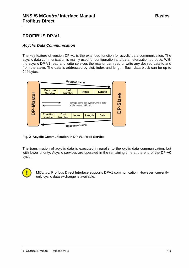
Acyclic Data Communication The key feature of version DP-V1 is the extended function for acyclic data communication. The acyclic data communication is mainly used for configuration and parameterization purpose. With the acyclic DP-V1 read and write services the master can read or write any desired data to and from the slave. The data is addressed by slot, index and length. Each data block can be up to 244 bytes.
Fig. 2 Acyclic Communication in DP-V1: Read Service
The transmission of acyclic data is executed in parallel to the cyclic data communication, but with lower priority. Acyclic services are operated in the remaining time at the end of the DP-V0 cycle.
MControl Profibus Direct Interface supports DPV1 communication. However, currently only cyclic data exchange is available.

Interfaces MNS iS MControl Interface ManualProfibus Direct
14 1TGC910187M0201 – Release V5.4
Interfaces
MControl Profibus connector Each MControl can be connected to the Profibus via a connector on the front side of the MControl. MControl acts as a standard PROFIBUS Slave device.
Fig. 3 MControl front view with PROFIBUS connector
Connection The physical medium for PROFIBUS-DP is RS-485, which allows 32 nodes in a single segment and 125 nodes in a network using 4 segments. Segments must be separated by using Repeater.
The PROFIBUS interface checks input signal for poll requests from master and detects the baud rate automatically (max Baud Rate = 12MBit).
Cable length may vary from 80-1200 m depending on transmission speed and repeater type in use. Cable length can be extended using fiber optic modems (yielding a more robust network). See reference document [4] for more details on cable connections and wiring.
PROFIBUS connector
LED Indication
LED 3 Red: not connected or
no communication
LED 4 Green: Communication running
MNS iS MControl Interface Manual Profibus Direct
Interfaces
1TGC910187M0201 – Release V5.4 15
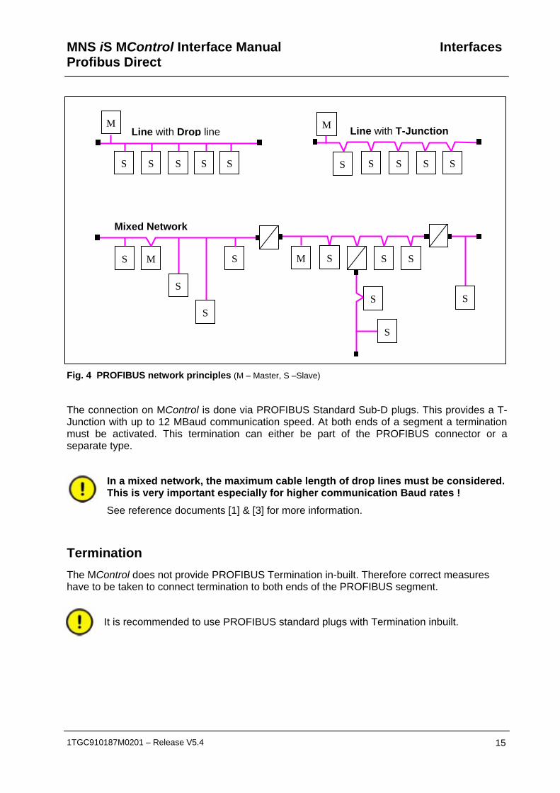
Fig. 4 PROFIBUS network principles (M – Master, S –Slave)
The connection on MControl is done via PROFIBUS Standard Sub-D plugs. This provides a T-Junction with up to 12 MBaud communication speed. At both ends of a segment a termination must be activated. This termination can either be part of the PROFIBUS connector or a separate type.
In a mixed network, the maximum cable length of drop lines must be considered. This is very important especially for higher communication Baud rates ! See reference documents [1] & [3] for more information.
Termination The MControl does not provide PROFIBUS Termination in-built. Therefore correct measures have to be taken to connect termination to both ends of the PROFIBUS segment.
It is recommended to use PROFIBUS standard plugs with Termination inbuilt.
Line with Drop line Line with T-Junction
Mixed Network
M M
S S
M M
S S S S S S S S
S
S
S
S S S
S
S
S
S
Interfaces MNS iS MControl Interface ManualProfibus Direct
16 1TGC910187M0201 – Release V5.4
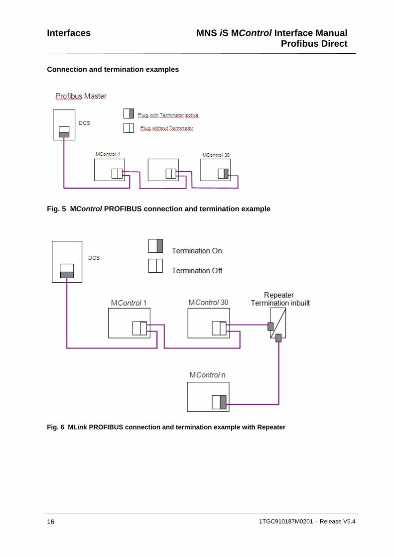
Connection and termination examples
Fig. 5 MControl PROFIBUS connection and termination example
Fig. 6 MLink PROFIBUS connection and termination example with Repeater
MNS iS MControl Interface Manual Profibus Direct
Getting Started
1TGC910187M0201 – Release V5.4 17
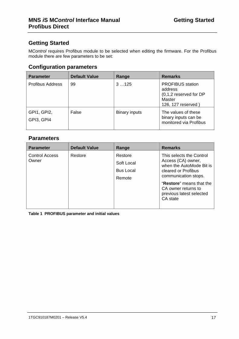
Getting Started MControl requires Profibus module to be selected when editing the firmware. For the Profibus module there are few parameters to be set:
Configuration parameters Parameter Default Value Range Remarks
Profibus Address 99 3 …125 PROFIBUS station address (0,1,2 reserved for DP Master 126, 127 reserved )
GPI1, GPI2,
GPI3, GPI4
False Binary inputs
The values of these binary inputs can be monitored via Profibus
Parameters Parameter Default Value Range Remarks
Control Access Owner
Restore Restore
Soft Local
Bus Local
Remote
This selects the Control Access (CA) owner, when the AutoMode Bit is cleared or Profibus communication stops.
“Restore” means that the CA owner returns to previous latest selected CA state
Table 1 PROFIBUS parameter and initial values

Getting Started MNS iS MControl Interface Manual Profibus Direct
18 1TGC910187M0201 – Release V5.4
Segment Segment
Segment Segment
2 . . . . .32 33 . . . . . 63
95. . . . . 125 64. . . . . 94
TerminationPROFIBUS Master DPM1
Addressing PROFIBUS DP allows the address range of 0 to 127. Following reservations apply:
0, 1, 2 - used for PROFIBUS Master
126, 127 - reserved
The remaining address numbers are available. It must be ensured that the number selected is unique for the PROFIBUS Master where the MControl is connected to. Using a number more than once will cause communication error on PROFIBUS.
MControl does not support address setting / changing from PROFIBUS Master. The address must be defined with the configuration parameter above and loaded into MControl.
If more than 32 devices are connected to a segment, repeater devices have to be used. Such repeater counts as one Slave within a segment without using an address number. Thus only 30 Slaves are possible within a segment.
Fig. 7 Example of max address range and slave numbers on one PROFIBUS Master
MNS iS MControl Interface Manual Profibus Direct
Getting Started
1TGC910187M0201 – Release V5.4 19
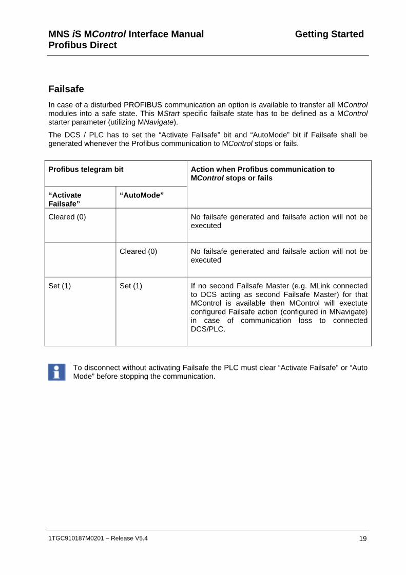
Failsafe In case of a disturbed PROFIBUS communication an option is available to transfer all MControl modules into a safe state. This MStart specific failsafe state has to be defined as a MControl starter parameter (utilizing MNavigate).
The DCS / PLC has to set the “Activate Failsafe” bit and “AutoMode” bit if Failsafe shall be generated whenever the Profibus communication to MControl stops or fails.
Profibus telegram bit
“Activate Failsafe”
“AutoMode”
Action when Profibus communication to MControl stops or fails
Cleared (0) No failsafe generated and failsafe action will not be executed
Cleared (0) No failsafe generated and failsafe action will not be executed
Set (1) Set (1) If no second Failsafe Master (e.g. MLink connected to DCS acting as second Failsafe Master) for that MControl is available then MControl will exectute configured Failsafe action (configured in MNavigate) in case of communication loss to connected DCS/PLC.
To disconnect without activating Failsafe the PLC must clear “Activate Failsafe” or “Auto Mode” before stopping the communication.
Data Mapping MNS iS MControl Interface ManualProfibus Direct
20 1TGC910187M0201 – Release V5.4
Control Access To request control via Profibus Direct the AutoMode bit must be set in the control structure:
• If the hardware local input is active the control will stay with the local inputs and the AutoMode bit inside the monitoring data will not be set.
• If the hardware local input is not active the MControl will accept the request and set the AutoMode bit in the monitoring data. Also the “CA MControl Fieldbus Interface” bit in the CA section of the MControl status is set. Then the MControl will follow the Profibus requests.
When clearing the AutoMode bit the control access owner will be set as specified in the setting of the parameter “Control Access Owner” of the direct Profibus interface.
To enable the control via MView, Gateways, RCU, etc. the AutoMode bit of the Profibus Direct interface must be cleared.

MNS iS MControl Interface Manual Profibus Direct
Data Mapping
1TGC910187M0201 – Release V5.4 21
PROFIBUS Data Mapping
General MControl supports
- the 2 PNO Standard Profibus profiles for Low Voltage Switchgear (Motor Management Starter Profile)
- a MControl proprietary full information profile
Profile type Monitoring data format
Command format
Remark
4read – 2write 0 0 Standard PNO profile Low Voltage Switchgear
4read – 4write 0 1 Standard PNO profile Low Voltage Switchgear
4read – 13write 0 2 Monitoring: Standard PNO profile Low Voltage Switchgear
Commands: MControl proprietary
244 read – 13 write 2 2 Monitoring: MControl proprietary
Commands: MControl proprietary
The standard profiles are based on the technical specification “Profiles for Low Voltage Switchgear, Version 1.2, July 2006).
Data Mapping MNS iS MControl Interface ManualProfibus Direct
22 1TGC910187M0201 – Release V5.4
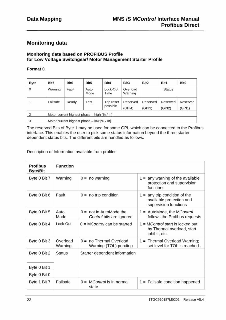
Monitoring data
Monitoring data based on PROFIBUS Profile for Low Voltage Switchgear/ Motor Management Starter Profile
Format 0
Byte Bit7 Bit6 Bit5 Bit4 Bit3 Bit2 Bit1 Bit0
0 Warning Fault
Auto Mode
Lock-Out Time
Overload Warning
Status
1 Failsafe Ready Test Trip reset possible
Reserved
(GPI4)
Reserved
(GPI3)
Reserved
(GPI2)
Reserved
(GPI1)
2 Motor current highest phase – high [% / In]
3 Motor current highest phase – low [% / In]
The reserved Bits of Byte 1 may be used for some GPI, which can be connected to the Profibus interface. This enables the user to pick some status information beyond the three starter dependent status bits. The different bits are handled as follows.
Description of Information available from profiles
Profibus Byte/Bit
Function
Byte 0 Bit 7 Warning 0 = no warning 1 = any warning of the available protection and supervision functions
Byte 0 Bit 6 Fault 0 = no trip condition 1 = any trip condition of the available protection and supervision functions
Byte 0 Bit 5 Auto Mode
0 = not in AutoMode the Control bits are ignored
1 = AutoMode, the MControl follows the Profibus requests
Byte 0 Bit 4 Lock-Out 0 = MControl can be started 1 = MControl start is locked out by Thermal overload, start inhibit, etc.
Byte 0 Bit 3 Overload Warning
0 = no Thermal Overload Warning (TOL) pending
1 = Thermal Overload Warning; set level for TOL is reached .
Byte 0 Bit 2
Byte 0 Bit 1
Byte 0 Bit 0
Status Starter dependent information
Byte 1 Bit 7 Failsafe 0 = MControl is in normal state
1 = Failsafe condition happened
MNS iS MControl Interface Manual Profibus Direct
Data Mapping
1TGC910187M0201 – Release V5.4 23
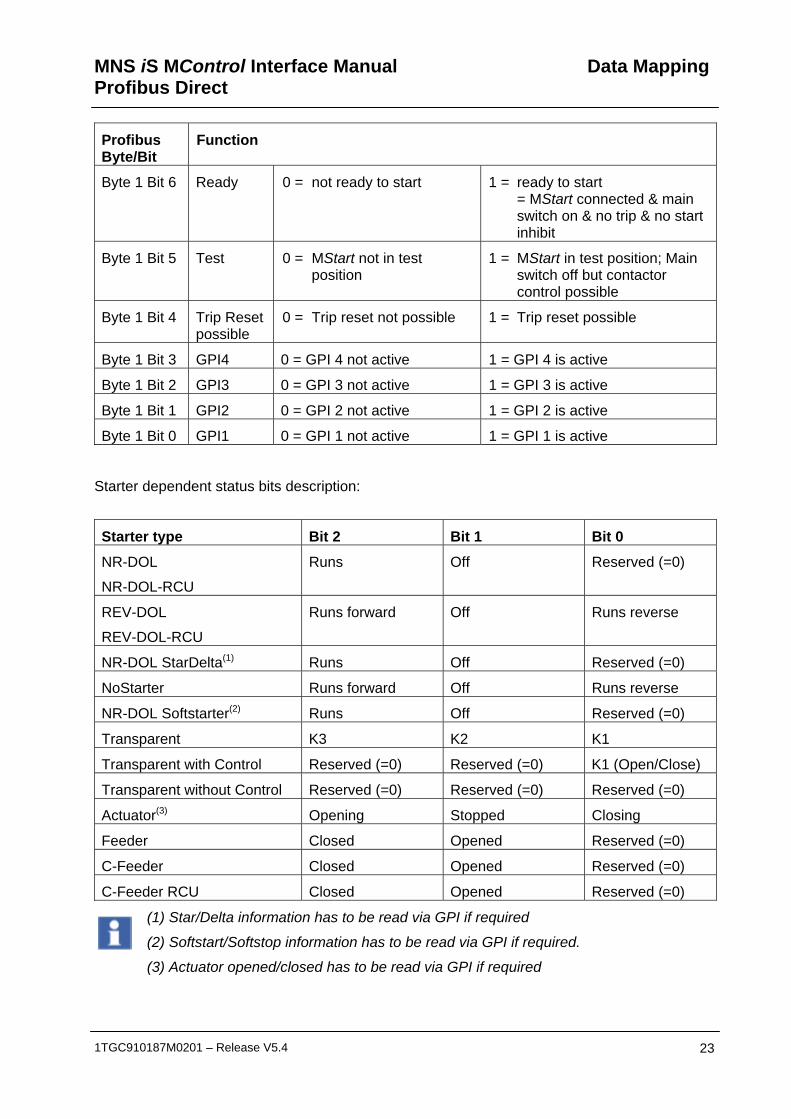
Profibus Byte/Bit
Function
Byte 1 Bit 6 Ready 0 = not ready to start 1 = ready to start = MStart connected & main switch on & no trip & no start inhibit
Byte 1 Bit 5 Test 0 = MStart not in test position
1 = MStart in test position; Main switch off but contactor control possible
Byte 1 Bit 4 Trip Reset possible
0 = Trip reset not possible 1 = Trip reset possible
Byte 1 Bit 3 GPI4 0 = GPI 4 not active 1 = GPI 4 is active
Byte 1 Bit 2 GPI3 0 = GPI 3 not active 1 = GPI 3 is active
Byte 1 Bit 1 GPI2 0 = GPI 2 not active 1 = GPI 2 is active
Byte 1 Bit 0 GPI1 0 = GPI 1 not active 1 = GPI 1 is active
Starter dependent status bits description:
Starter type Bit 2 Bit 1 Bit 0
NR-DOL
NR-DOL-RCU
Runs Off Reserved (=0)
REV-DOL
REV-DOL-RCU
Runs forward Off Runs reverse
NR-DOL StarDelta(1) Runs Off Reserved (=0)
NoStarter Runs forward Off Runs reverse
NR-DOL Softstarter(2) Runs Off Reserved (=0)
Transparent K3 K2 K1
Transparent with Control Reserved (=0) Reserved (=0) K1 (Open/Close)
Transparent without Control Reserved (=0) Reserved (=0) Reserved (=0)
Actuator(3) Opening Stopped Closing
Feeder Closed Opened Reserved (=0)
C-Feeder Closed Opened Reserved (=0)
C-Feeder RCU Closed Opened Reserved (=0)
(1) Star/Delta information has to be read via GPI if required
(2) Softstart/Softstop information has to be read via GPI if required.
(3) Actuator opened/closed has to be read via GPI if required

Data Mapping MNS iS MControl Interface ManualProfibus Direct
24 1TGC910187M0201 – Release V5.4
Format 2 This format delivers the full information as displayed on the MView.
Note : This layout is only valid for MControl Base Version 5.4 !
Prof
ibus
B
yte
offs
et
Bit
offs
et Data type Description
0 0
Unsigned32
QualityCode:
Bit field with bits indicating whether measurement values are valid.
See tables below !
4 0
Unsigned32
QualityCode2:
Bit field with bits indicating whether measurement values are valid.
See tables below !
8 0 Unsigned32
MControl status
See tables below !
12 0 Floating point Current phase 1 [A]
16 0 Floating point Current phase 2 [A]
20 0 Floating point Current phase 3 [A]
24 0 Unsigned16 Current phase 1 [%]
26 0 Unsigned16 Current phase 2 [%]
28 0 Unsigned16 Current phase 3 [%]
30 0 Floating point Earth fault current [A].
34 0 Floating point Phase 1-2 Voltage [V], Phase 1 Voltage [V]
38 0 Floating point Phase 2-3 Voltage [V]
42 0 Floating point Phase 3-1 Voltage [V]
46 0 Floating point Cos Phi (calculated)
50 0 Floating point Frequency [Hz]
54 0 Floating point Apparent power [0.1 kVA]5)
58 0 Floating point Active power [0.1 kW] 5)
62 0 Floating point Reactive power [0.1 kVAR] 5)
66 0 Floating point Temperature of contact L1 [ °C]
70 0 Floating point Temperature of contact L2 [°C]
74 0 Floating point Temperature of contact L3 [°C]
78 0 Unsigned32 K1 switching cycles
82 0 Unsigned32 K2 switching cycles
86 0 Unsigned32 K3 switching cycles
90 0 Unsigned32 MStart insertion cycles
94 0 Unsigned32 Operating hours [h]

MNS iS MControl Interface Manual Profibus Direct
Data Mapping
1TGC910187M0201 – Release V5.4 25
Prof
ibus
B
yte
offs
et
Bit
offs
et Data type Description
98 0 Unsigned16 Thermal image [%]
100 0 Unsigned16 Time to reset [s]
102 0 Unsigned16 Time to trip [s]
104 0 Unsigned16 Measured PTC resistance [Ω]
106 0 Integer16 PT100-3Ch Temperature Sensor1 [0.1 °C] 4) (only if respective HW available)
108 0 Integer16 PT100-3Ch Temperature Sensor2 [0.1 °C] 4) (only if respective HW available)
110 0 Integer16 PT100-3Ch Temperature Sensor3 [0.1 °C] 4) (only if respective HW available)
112 0 Unsigned16 GPI: Up to 16 user assigned input signals
114 0 Unsigned16 GPAI: User configurable Analog value (mostly [0.1 %]5) )
116 0 Floating point Motor start time [s]
120 0
Floating point Current at trip phase 1 [A]
124 0
Floating point Current at trip phase 2 [A]
128 0
Floating point Current at trip phase 3 [A]
132 0
Unsigned8 Quality code bit field to indicate whether current at trip is valid:
Bit 7: no current at trip stored
Bit 2: Current at trip L3 not valid
Bit 1: Current at trip L2 not valid
Bit 0: Current at trip L1 not valid
133 0 Unsigned8 Always zero
134 0 Integer16 MControl Base Version5)
136 0 Unsigned8 UUID read from MStart
142 0 TimeStampT6) The timestamp of the last Earo Entry change
150 0 EaroEntryT1) TOL/TOL Eexe
151 0 EaroEntryT1) PTC supervision
152 0 EaroEntryT1) PTC short circuit
153 0 EaroEntryT1) PTC open circuit
154 0 EaroEntryT1) Underload
155 0 EaroEntryT1) Underload CosPhi
156 0 EaroEntryT1) Phase failure
157 0 EaroEntryT1) -unused-
158 0 EaroEntryT1) -unused-

Data Mapping MNS iS MControl Interface ManualProfibus Direct
26 1TGC910187M0201 – Release V5.4
Prof
ibus
B
yte
offs
et
Bit
offs
et Data type Description
159 0 EaroEntryT1) Phase Unbalance
160 0 EaroEntryT1) UnderVoltage
161 0 EaroEntryT1) ControlVoltage
162 0 EaroEntryT1) Start limitation
163 0 EaroEntryT1) AutorestartInhibit
164 0 EaroEntryT1) -unused-
165 0 EaroEntryT1) EmStop
166 0 EaroEntryT1) MainSwitchSupervision
167 0 EaroEntryT1) FeedbackSupervision (K1)
168 0 EaroEntryT1) FeedbackSupervision (K2)
168 4 EaroEntryT1) Feeder MCB trip
169 0 EaroEntryT1) FeedbackSupervision (K3)
170 0 EaroEntryT1) MotorStillRunning
170 4 EaroEntryT1) Unexpected feeder current
171 0 EaroEntryT1) Motor not running
172 0 EaroEntryT1) Welded
173 0 EaroEntryT1) Testmode failure
174 0 EaroEntryT1) NoLoad
175 0 EaroEntryT1) Stall
176 0 EaroEntryT1) Earth Leakage
177 0 EaroEntryT1) Contact Temperature Unbalance
178 0 EaroEntryT1) External Trip 1
179 0 EaroEntryT1) External Trip 2
180 0 EaroEntryT1) IRF (Hardware)
181 0 EaroEntryT1) Actuator: both end switch active
182 0 EaroEntryT1) Actuator: Torque open
183 0 EaroEntryT1) Actuator: Torque close
184 0 EaroEntryT1) -unused-
185 0 EaroEntryT1) PT100-1Ch Card Failure (following data only if respective HW available)
186 0 EaroEntryT1) PT100-1Ch Sensor Low Limit
186 4 EaroEntryT1) PT100-1Ch Sensor Short Circuit
187 0 EaroEntryT1) PT100-1Ch Sensor High Limit
187 4 EaroEntryT1) PT100-1Ch Sensor Open Circuit
188 0 EaroEntryT1) PT100-3Ch Card Failure (following data only if respective HW available))
189 0 EaroEntryT1) PT100-3Ch Sensor1 Low Limit
189 4 EaroEntryT2) PT100-3Ch Sensor1 Short Circuit
MNS iS MControl Interface Manual Profibus Direct
Data Mapping
1TGC910187M0201 – Release V5.4 27
Prof
ibus
B
yte
offs
et
Bit
offs
et Data type Description
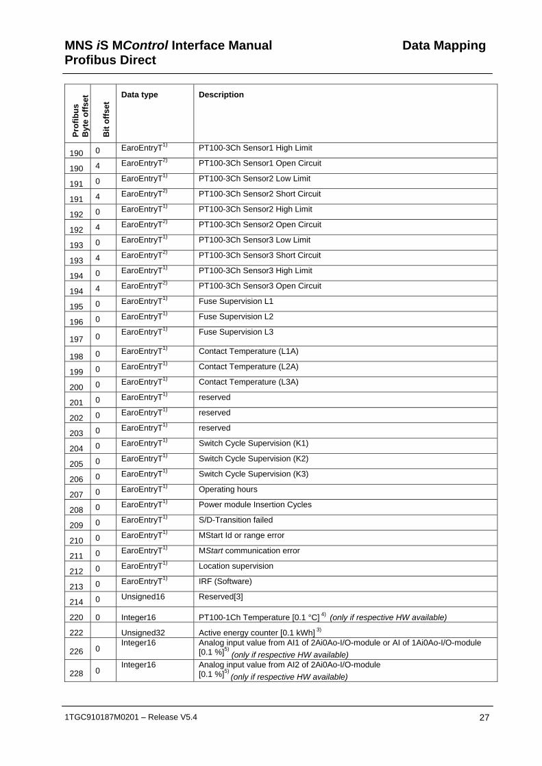
190 0 EaroEntryT1) PT100-3Ch Sensor1 High Limit
190 4 EaroEntryT2) PT100-3Ch Sensor1 Open Circuit
191 0 EaroEntryT1) PT100-3Ch Sensor2 Low Limit
191 4 EaroEntryT2) PT100-3Ch Sensor2 Short Circuit
192 0 EaroEntryT1) PT100-3Ch Sensor2 High Limit
192 4 EaroEntryT2) PT100-3Ch Sensor2 Open Circuit
193 0 EaroEntryT1) PT100-3Ch Sensor3 Low Limit
193 4 EaroEntryT2) PT100-3Ch Sensor3 Short Circuit
194 0 EaroEntryT1) PT100-3Ch Sensor3 High Limit
194 4 EaroEntryT2) PT100-3Ch Sensor3 Open Circuit
195 0 EaroEntryT1) Fuse Supervision L1
196 0 EaroEntryT1) Fuse Supervision L2
197 0 EaroEntryT1) Fuse Supervision L3
198 0 EaroEntryT1) Contact Temperature (L1A)
199 0 EaroEntryT1) Contact Temperature (L2A)
200 0 EaroEntryT1) Contact Temperature (L3A)
201 0 EaroEntryT1) reserved
202 0 EaroEntryT1) reserved
203 0 EaroEntryT1) reserved
204 0 EaroEntryT1) Switch Cycle Supervision (K1)
205 0 EaroEntryT1) Switch Cycle Supervision (K2)
206 0 EaroEntryT1) Switch Cycle Supervision (K3)
207 0 EaroEntryT1) Operating hours
208 0 EaroEntryT1) Power module Insertion Cycles
209 0 EaroEntryT1) S/D-Transition failed
210 0 EaroEntryT1) MStart Id or range error
211 0 EaroEntryT1) MStart communication error
212 0 EaroEntryT1) Location supervision
213 0 EaroEntryT1) IRF (Software)
214 0 Unsigned16 Reserved[3]
220 0 Integer16 PT100-1Ch Temperature [0.1 °C] 4) (only if respective HW available)
222 Unsigned32 Active energy counter [0.1 kWh] 3)
226 0 Integer16 Analog input value from AI1 of 2Ai0Ao-I/O-module or AI of 1Ai0Ao-I/O-module
[0.1 %]5) (only if respective HW available)
228 0 Integer16 Analog input value from AI2 of 2Ai0Ao-I/O-module
[0.1 %]5) (only if respective HW available)

Data Mapping MNS iS MControl Interface ManualProfibus Direct
28 1TGC910187M0201 – Release V5.4
Prof
ibus
B
yte
offs
et
Bit
offs
et Data type Description
232-244
0 Unsigned8 Reserved space all filled with 0
1) Bit field maps to the lower 4 bit (3,2,1,0) of the byte: (0, trip acknowledged, trip new, alarm) 2) Bit field maps to the higher 4 bit (7,6,5,4) of the byte: (0, trip acknowledged, trip new, alarm) 3) Transferred value is multiplied by 10 to allow for 1 fractional digit. The value 1234 means 123.4 kWh 4) Transferred value is multiplied by 10 to allow for 1 fractional digit. The value 1234 means 123.4 °C 5) Transferred value is multiplied by 10 to allow for 1 fractional digit. The value 1234 means 123.4 6) TimestampT is a timestamp with this format:
Byte DataType Contents
1 Unsigned8 Year: 0(*), 1 … 199
2 Unsigned8 Month: 0(*), 1 … 12
3 Unsigned8 Day: 0(*), 1 … 31
4 Unsigned8 Hour: 0 … 23
5 Unsigned8 Minute: 0 … 59
6 Unsigned8 Second: 0 … 59
7,8 Unsigned8 Millisecond: 0 … 999 (*) If the timestamp is invalid the entries for Year, Month and
Day are set to zero!
QualityCode The quality codes are bit fields indicating whether the measurement values are valid.
• If the bit is cleared data value is valid.
• If the bit is set the data value is invalid
QualityCode1
Bit
Data
31 reserved
30 MStart insertion cycles
29 K1, K2, K3 switching cycles
28 reserved
27 reserved
26 reserved
25 reserved

MNS iS MControl Interface Manual Profibus Direct
Data Mapping
1TGC910187M0201 – Release V5.4 29
QualityCode1
Bit
Data
24 reserved
23 reserved
22 Frequency
21 Reactive power
20 Active power
19 Apparent power
18 Cos Phi
17 reserved
16 reserved
15 reserved
14 Temperature of contact L3
13 Temperature of contact L2
12 Temperature of contact L1
11 reserved
10 reserved
9 reserved
8 Phase 3-1 Voltage
7 Phase 2-3 Voltage
6 Phase 1-2 Voltage, Phase 1 Voltage
5 Earth fault current
4 Current phase 3
3 Current phase 2
2 Current phase 1
1 reserved
0 reserved
QualityCode2 Bit
Data
31 Thermal image
30 Time to reset
29 Time to trip
28 AI2 (2Ai0Ao)
27 AI (1Ai1Ao) / AI1 (2Ai0Ao)
26 PTC resistance (only if respective HW available)

Data Mapping MNS iS MControl Interface ManualProfibus Direct
30 1TGC910187M0201 – Release V5.4
QualityCode2 Bit
Data
25 Reserved
24 Motor start time
23 Reserved
22 PT100_3CH_Temperature3 (only if respective HW available)
21 PT100_3CH_Temperature2 (only if respective HW available)
20 PT100_3CH_Temperature1 (only if respective HW available)
19 PT100_1CH_Temperature (only if respective HW available)
18 reserved
17 reserved
16 reserved
15 GPI16
14 GPI15
13 GPI14
12 GPI13
11 GPI12
10 GPI11
9 GPI10
8 GPI9
7 GPI8
6 GPI7
5 GPI6
4 GPI5
3 GPI4
2 GPI3
1 GPI2
0 GPI1

MNS iS MControl Interface Manual Profibus Direct
Data Mapping
1TGC910187M0201 – Release V5.4 31
MControl status Section Bits Notes
31 Remote
30 MControl Fieldbus Interface
29 Reserved
28 Reserved
27 Reserved
26 Reserved
25 HMI Local (MView)
24 Soft Local
Con
trol A
cces
s O
wne
r
23 Hardware Local
23 Set if TOL bypass is activated
22 Set if TOL startup inhibit is active
21 Set if MControl is locked out: The MControl can not be started due to TOL startup inhibit or an input signal
20 Set if MStart is in isolated position
19 Must be 0: Reserved for future use.
18 Must be 0: Reserved for future use.
17 Set if main switch is in on position
Var
ious
inpu
t sig
nals
16 Set if test switch is in on position
0 15-13 Starter dependent information
Failsafe 12 Starter entered failsafe status
11 Reserved
10 Trip Acknowledged
9 Trip New
Ear
oEnt
ryT
8 Alarm
State 7-0 Starter dependent information

Data Mapping MNS iS MControl Interface ManualProfibus Direct
32 1TGC910187M0201 – Release V5.4
Starter dependent information
Bits
NR
-DO
L
NR
-DO
L R
CU
REV
-DO
L
REV
-DO
L R
CU
NoS
tart
er
NR
-DO
l Sta
rDel
ta
NrD
ol S
ofts
tart
er
Act
uato
r
Tran
spar
ent
(with
/with
out C
ontr
ol)
Feed
er
C-F
eede
r
C-F
eede
r RC
U
15 0 0 0 0 1 0 0 1 0 1 1 1
14 0 1 0 1 1 0 1 0 0 1 1 1
13 0 1 0 1 1 1 0 0 0 0 0 0
7
Rea
dy
Rea
dy
Rea
dy
Rea
dy
Rea
dy
Rea
dy
Rea
dy
Rea
dy
Rea
dy
0
Rea
dy
Rea
dy
6 0 0 0 0
(Run
s)
Sta
r
Sof
tsta
rt
0 Ope
n P
ositi
on
0 0 0 0
5 0 0 0 0 0
Sof
tsto
p
0 Clo
se
Pos
ition
0 0 0 0
4 0 0
(Run
s)
CC
W
(Run
s)
CC
W
0 0 0 0 K3 0 0 0
3 0 0
(Run
s)
CW
(Run
s)
CW
0 0
(Run
s)
CC
W
(Run
s)
open
K2 0 0 0
2 0 0 Run
s
Run
s
0 0
(Run
s)
CW
(Run
s)
clos
e
K1 0 0 0
1 Run
s
Run
s
Stop
ped
Stop
ped
Run
s
Run
s
Run
s
Run
s
0
Clo
sed
Clo
sed
Clo
sed
0
Stop
ped
Stop
ped
Stop
ped
Stop
ped
Stop
ped
Stop
ped
Stop
ped
Sto
pped
0
Ope
ned
Ope
ned
Ope
ned

MNS iS MControl Interface Manual Profibus Direct
Data Mapping
1TGC910187M0201 – Release V5.4 33
Command format The command data are available in 3 formats:
- Format 0
- Format 1
- Format 2
Each format extends the range of control.
The control via Profibus depends very much on the “Auto-Mode”-Bit of the control structure. Whenever this Bit is set and “HW-Local” is not active the control is possible via Profibus.
To avoid future incompatibilities all unused and reserved bits in the command structure must be set to 0.
Format 0: Byte Bit7 Bit6 Bit5 Bit4 Bit3 Bit2 Bit1 Bit0
0 Reserved Trip Reset
Auto-Mode
Unused Unused Starter Control
1
Failsafe activate
Reserved Reserved Reserved Reserved Reserved Reserved Reserved
Format 1: Byte Bit7 Bit6 Bit5 Bit4 Bit3 Bit2 Bit1 Bit0
0 Reserved Trip Reset
Auto-Mode
Unused Unused Starter Control
1
Failsafe activate
Reserved Reserved Reserved Reserved Reserved Reserved Reserved
2
GO7 GO6 GO5 GO4 GO3 GO2 GO1 GO0
3
Reserved Reserved Reserved Reserved Reserved Reserved Reserved Reserved
Data Mapping MNS iS MControl Interface ManualProfibus Direct
34 1TGC910187M0201 – Release V5.4
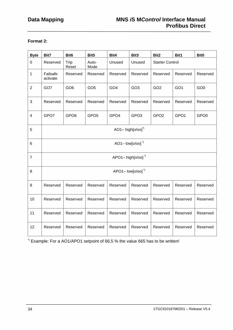
Format 2:
Byte Bit7 Bit6 Bit5 Bit4 Bit3 Bit2 Bit1 Bit0
0 Reserved Trip Reset
Auto-Mode
Unused Unused Starter Control
1
Failsafe activate
Reserved Reserved Reserved Reserved Reserved Reserved Reserved
2
GO7 GO6 GO5 GO4 GO3 GO2 GO1 GO0
3
Reserved Reserved Reserved Reserved Reserved Reserved Reserved Reserved
4
GPO7 GPO6 GPO5 GPO4 GPO3 GPO2 GPO1 GPO0
5
AO1– high[o/oo]*)
6
AO1– low[o/oo] *)
7
APO1– high[o/oo] *)
8
APO1– low[o/oo] *)
9
Reserved Reserved Reserved Reserved Reserved Reserved Reserved Reserved
10
Reserved Reserved Reserved Reserved Reserved Reserved Reserved Reserved
11
Reserved Reserved Reserved Reserved Reserved Reserved Reserved Reserved
12
Reserved Reserved Reserved Reserved Reserved Reserved Reserved Reserved
*) Example: For a AO1/APO1 setpoint of 66,5 % the value 665 has to be written!

MNS iS MControl Interface Manual Profibus Direct
Data Mapping
1TGC910187M0201 – Release V5.4 35
The starter dependent control bits are encoded as follows:
Starter type Bit 2 Bit 1 Bit 0
NR-DOL
NR-DOL-RCU
Start Stop Reserved (=0)
REV-DOL
REV-DOL-RCU
Start CW Stop Start CCW
NR-DOL StarDelta Start Stop Reserved (=0)
NoStarter Start CW Stop Start CCW
NR-DOL Softstarter Start Stop Reseverd (=0)
Transparent K3 K2 K1
Transparent with Control Reserved (=0) Reserved (=0) K1 (Open/Close)
Transparent without Control Reserved (=0) Reserved (=0) Reserved (=0)
Actuator Start open Stopped Start close
Feeder Reserved (=0) Reserved (=0) Reserved (=0)
C-Feeder Close Open Reserved (=0)
C-Feeder RCU Close Open Reserved (=0)
If “Stop” is set the starter is stopped and the other bits are invalid.
“Start CW” and “Start CCW” as well as “K1” and “K2” may not be set simultaneously.
If Actuator is open “Start open” command is ignored. If Actuator is closed “Start close” command is ignored.
Profibus Byte/Bit
Function
Byte 0 Bit 6 Trip Reset 1 = if there are resettable trips the trips are reset
Byte 0 Bit 5 Auto Mode
1 = the control is passed to Profibus if CA=”Hardware Local” is not active.
Byte 0 Bit 2
Byte 0 Bit 1
Byte 0 Bit 0
Starter Control
Starter dependent Control bits (see table above)
Byte 1 Bit 7 Failsafe 1 = Profibus master is failsafe master
Byte 2 Bit 7 GO 7 General purpose out 7 will follow this bit as long as AutoMode is set
Byte 2 Bit 6 GO 6 General purpose out 6 will follow this bit as long as AutoMode is set
Byte 2 Bit 5 GO 5 General purpose out 5 will follow this bit as long as AutoMode is set
Data Mapping MNS iS MControl Interface ManualProfibus Direct
36 1TGC910187M0201 – Release V5.4
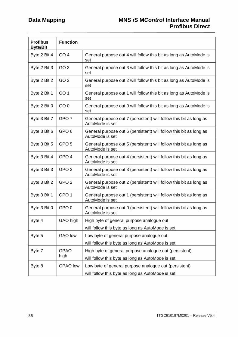
Profibus Byte/Bit
Function
Byte 2 Bit 4 GO 4 General purpose out 4 will follow this bit as long as AutoMode is set
Byte 2 Bit 3 GO 3 General purpose out 3 will follow this bit as long as AutoMode is set
Byte 2 Bit 2 GO 2 General purpose out 2 will follow this bit as long as AutoMode is set
Byte 2 Bit 1 GO 1 General purpose out 1 will follow this bit as long as AutoMode is set
Byte 2 Bit 0 GO 0 General purpose out 0 will follow this bit as long as AutoMode is set
Byte 3 Bit 7 GPO 7 General purpose out 7 (persistent) will follow this bit as long as AutoMode is set
Byte 3 Bit 6 GPO 6 General purpose out 6 (persistent) will follow this bit as long as AutoMode is set
Byte 3 Bit 5 GPO 5 General purpose out 5 (persistent) will follow this bit as long as AutoMode is set
Byte 3 Bit 4 GPO 4 General purpose out 4 (persistent) will follow this bit as long as AutoMode is set
Byte 3 Bit 3 GPO 3 General purpose out 3 (persistent) will follow this bit as long as AutoMode is set
Byte 3 Bit 2 GPO 2 General purpose out 2 (persistent) will follow this bit as long as AutoMode is set
Byte 3 Bit 1 GPO 1 General purpose out 1 (persistent) will follow this bit as long as AutoMode is set
Byte 3 Bit 0 GPO 0 General purpose out 0 (persistent) will follow this bit as long as AutoMode is set
Byte 4 GAO high High byte of general purpose analogue out
will follow this byte as long as AutoMode is set
Byte 5 GAO low Low byte of general purpose analogue out
will follow this byte as long as AutoMode is set
Byte 7 GPAO high
High byte of general purpose analogue out (persistent)
will follow this byte as long as AutoMode is set
Byte 8 GPAO low Low byte of general purpose analogue out (persistent)
will follow this byte as long as AutoMode is set


Contact us ABB Low Voltage Systems Publication Editor: ABB Automation Products GmbH Ladenburg, Germany Local Contacts on www.abb.com/mns
Copyright© 2009 ABB All rights reserved. Publication No. 1TGC910187M0201


