Mobile Access Portal Gateway Installation Instructions Part No. 24-10737-8, Rev. F Software Release 4.0 Issued April 2016 Refer to the QuickLIT website for the most up-to-date version of this document. Applications The Mobile Access Portal (MAP) Gateway is an alternate local display solution or a temporary portable commissioning device that enables users to leverage the power of mobility using smart phones, tablets, or laptop computers to interact with building automation equipment controls. The MAP Gateway serves up web pages through a built-in Wi-Fi access point or tethered Ethernet connection, which allows users to view and edit equipment controller configuration parameters, setpoints, schedules, and alarms through a browser. A mobile application is not required to use the MAP Gateway with your mobile device. The MAP Gateway can be used to see field bus devices on Metasys® systems, Facility Explorer systems, and Smart Equipment rooftop units (RTUs) with unit control boards (UCBs). The MAP Gateway supports Johnson Controls® branded Field Controllers, including FEC, FAC, VMA, PCA, PCG, and PCV Series devices. MAP Gateway also supports the TEC3000 Series Thermostats. The wireless connection on the MAP Gateway allows users of a supported mobile device to be up to 30 m (100 ft, line of sight) away indoors and up to 91 m (300 ft, line of sight) away outdoors. Power may be supplied via the SAB (sensor/actuator bus), the FCB (field controller bus), a supplied external power supply, or a micro USB port. The MAP Gateway comes in two configurations: a portable configuration and a stationary configuration. Configuration is chosen at purchase, and the accessories shipped with the MAP Gateway depend on the configuration chosen. When used as a portable device, the MAP Gateway can be attached to a lanyard. In this configuration, the MAP Gateway can be carried from site to site, depending on the needs and workflow of field personnel. When used as a stationary device, the MAP Gateway can be permanently mounted directly to a wall or DIN rail using the supplied MAP Gateway mounting cradle. North American Emissions Compliance United States This equipment has been tested and found to comply with the limits for a Class A digital device pursuant to Part 15 of the FCC Rules. These limits are designed to provide reasonable protection against harmful interference when this equipment is operated in a commercial environment. This equipment generates, uses, and can radiate radio frequency energy and, if not installed and used in accordance with the instruction manual, may cause harmful interference to radio communications. Operation of this equipment in a residential area may cause harmful interference, in which case the users will be required to correct the interference at their own expense. RF Transmitters: Compliance Statement (Part 15.19) This device complies with Part 15 of the FCC Rules. Operation is subject to the following two conditions: 1. This device may not cause harmful interference, and 2. This device must accept any interference received, including interference that may cause undesired operation. Warning (Part 15.21) Changes or modifications not expressly approved by the party responsible for compliance could void the user’s authority to operate the equipment. RF Exposure (OET Bulletin 65) To comply with FCC RF exposure requirements for mobile transmitting devices, this transmitter should only be used or installed at locations where there is at least 20 cm separation distance between the antenna and all persons. 1 Mobile Access Portal Gateway Installation Instructions
Transcript
Mobile Access Portal Gateway Installation InstructionsPart No. 24-10737-8, Rev. F
Software Release 4.0Issued April 2016
Refer to the QuickLIT website for the most up-to-date version of this document.
ApplicationsTheMobile Access Portal (MAP) Gateway is an alternatelocal display solution or a temporary portablecommissioning device that enables users to leverage thepower of mobility using smart phones, tablets, or laptopcomputers to interact with building automation equipmentcontrols. TheMAPGateway serves upweb pages througha built-in Wi-Fi access point or tethered Ethernetconnection, which allows users to view and editequipment controller configuration parameters, setpoints,schedules, and alarms through a browser. A mobileapplication is not required to use the MAP Gateway withyour mobile device.
The MAP Gateway can be used to see field bus deviceson Metasys® systems, Facility Explorer systems, andSmart Equipment rooftop units (RTUs) with unit controlboards (UCBs). The MAP Gateway supportsJohnson Controls® branded Field Controllers, includingFEC, FAC, VMA, PCA, PCG, and PCV Series devices.MAP Gateway also supports the TEC3000 SeriesThermostats.
The wireless connection on the MAP Gateway allowsusers of a supported mobile device to be up to 30 m (100ft, line of sight) away indoors and up to 91 m (300 ft, lineof sight) away outdoors. Power may be supplied via theSAB (sensor/actuator bus), the FCB (field controller bus),a supplied external power supply, or a micro USB port.
The MAP Gateway comes in two configurations: aportable configuration and a stationary configuration.Configuration is chosen at purchase, and the accessoriesshipped with the MAP Gateway depend on theconfiguration chosen.
When used as a portable device, the MAP Gateway canbe attached to a lanyard. In this configuration, the MAPGateway can be carried from site to site, depending onthe needs and workflow of field personnel.
When used as a stationary device, the MAP Gatewaycan be permanently mounted directly to a wall or DIN railusing the supplied MAP Gateway mounting cradle.
North American EmissionsCompliance
United StatesThis equipment has been tested and found to complywith the limits for a Class A digital device pursuant toPart 15 of the FCC Rules. These limits are designed toprovide reasonable protection against harmfulinterference when this equipment is operated in acommercial environment. This equipment generates,uses, and can radiate radio frequency energy and, if notinstalled and used in accordance with the instructionmanual, may cause harmful interference to radiocommunications. Operation of this equipment in aresidential areamay cause harmful interference, in whichcase the users will be required to correct the interferenceat their own expense.
This device complies with Part 15 of the FCC Rules.Operation is subject to the following two conditions:
1. This device may not cause harmful interference, and2. This device must accept any interference received,
including interference that may cause undesiredoperation.
Warning (Part 15.21)
Changes or modifications not expressly approved by theparty responsible for compliance could void the user’sauthority to operate the equipment.
RF Exposure (OET Bulletin 65)
To comply with FCC RF exposure requirements formobile transmitting devices, this transmitter should onlybe used or installed at locations where there is at least20 cm separation distance between the antenna and allpersons.
CanadaIndustry Canada StatementThe term IC before the certification/registration numberonly signifies that the Industry Canada technicalspecifications were met.
Le terme « IC » précédant le numérod'accréditation/inscription signifie simplement que leproduit est conforme aux spécifications techniquesd'Industry Canada.
InstallationObserve the following guidelines:
• Verify that all parts shipped with the MAP Gateway.• Keep the unit encased in the protective shell. If not
protected by the enclosure in which it ships, the MAPGateway may be subject to physical damage.
Parts Included (Portable Model)• MAP Gateway• Protective shell• 6-pin RJ-12 connector cable• Lanyard• Installation Instructions• Mobile Access Portal Gateway Quick Start Guide
(Part No. 24-10737-16)
Parts Included (Stationary Model)• MAP Gateway• Field bus adapter• Mounting bracket (with locking screw)• Installation Instructions• Mobile Access Portal Gateway Quick Start Guide
(Part No. 24-10737-16)
Special Tools NeededTo use the MAP Gateway, you need a mobile device(tablet or smart phone) or computer (laptop or desktop)that supports Wi-Fi.
If the unit is permanently mounted to a vertical surfacewithout a DIN rail, you need screws to mount the unit.The specific screw types depend upon the surface towhich the unit is mounted. The screw holes on the MAPGateway can accommodate M3.5 and #6 screws.
Use of the mounting bracket locking screw requires aT15 Torx driver.
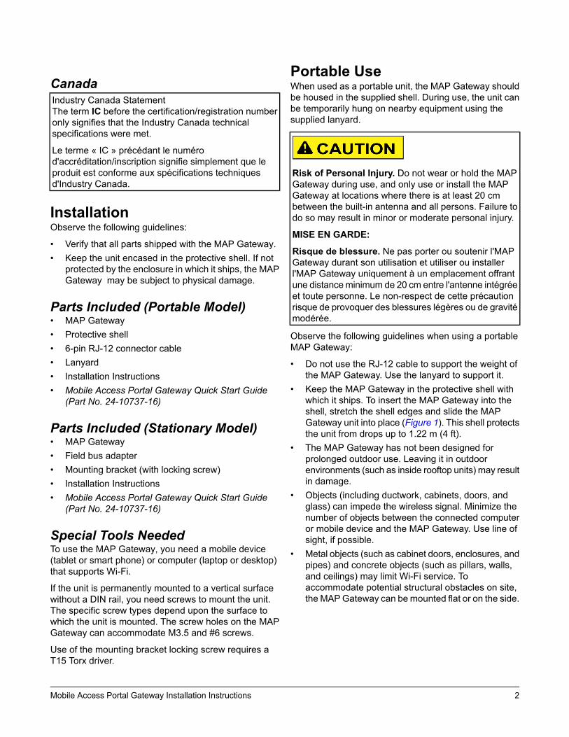
Portable UseWhen used as a portable unit, the MAP Gateway shouldbe housed in the supplied shell. During use, the unit canbe temporarily hung on nearby equipment using thesupplied lanyard.
Risk of Personal Injury. Do not wear or hold the MAPGateway during use, and only use or install the MAPGateway at locations where there is at least 20 cmbetween the built-in antenna and all persons. Failure todo so may result in minor or moderate personal injury.
MISE EN GARDE:
Risque de blessure. Ne pas porter ou soutenir l'MAPGateway durant son utilisation et utiliser ou installerl'MAP Gateway uniquement à un emplacement offrantune distanceminimum de 20 cm entre l'antenne intégréeet toute personne. Le non-respect de cette précautionrisque de provoquer des blessures légères ou de gravitémodérée.
Observe the following guidelines when using a portableMAP Gateway:
• Do not use the RJ-12 cable to support the weight ofthe MAP Gateway. Use the lanyard to support it.
• Keep the MAP Gateway in the protective shell withwhich it ships. To insert the MAP Gateway into theshell, stretch the shell edges and slide the MAPGateway unit into place (Figure 1). This shell protectsthe unit from drops up to 1.22 m (4 ft).
• The MAP Gateway has not been designed forprolonged outdoor use. Leaving it in outdoorenvironments (such as inside rooftop units) may resultin damage.
• Objects (including ductwork, cabinets, doors, andglass) can impede the wireless signal. Minimize thenumber of objects between the connected computeror mobile device and the MAP Gateway. Use line ofsight, if possible.
• Metal objects (such as cabinet doors, enclosures, andpipes) and concrete objects (such as pillars, walls,and ceilings) may limit Wi-Fi service. Toaccommodate potential structural obstacles on site,the MAPGateway can bemounted flat or on the side.
Risk of Property Damage. Do not use the RJ-12 cableor any other field bus cable or electrical cable to supportthe weight of the MAP Gateway. Hanging the MAPGateway from anything other than the supplied lanyardmay result in damage to the product or peripheralequipment.
MISE EN GARDE:
Risque de dégâts matériels. Ne pas utiliser le câbleRJ-12 ou tout autre câble de bus de terrain ou câbleélectrique pour soutenir le poids de l'MAP Gateway. Lasuspension de l'MAP Gateway à tout autre élément quela longe fournie risque d'endommager le produit ou leséquipements périphériques.
Figure 1: Portable MAPGateway and Protective Shell
Mounting
PermanentWhen used in a stationary configuration, the MAPGateway is permanently mounted using a bracket whichis provided with the stationary MAP Gateway. Werecommend the following three ways to mount the unit:vertically (upright and flush), horizontally (sideways andflush), or perpendicularly (perpendicular to the wall). Thisflexibility allows the unit to be mounted in a way thatminimizes spacial constraints and maximizes placementoptions for optimal wireless signal strength.
The unit should be mounted in such a way that labelscan be read if they are visible. (For example, do not mountthe unit upside down, which puts the labels upside down.)
Location ConsiderationsObserve the following guidelines when mounting a MAPGateway:
• Mount the MAP Gateway in areas free of corrosivevapors and observe the environmental limitationslisted in the Technical Specifications section of thisdocument.
• Objects (including ductwork, cabinets, doors, andglass) can impede the wireless signal. Minimize thenumber of objects between the connected computeror mobile device computer and the MAP Gateway.Use line of sight, if possible.
• Metal objects (such as cabinet doors, enclosures, andpipes) and concrete objects (such as pillars, walls,and ceilings) may limit Wi-Fi service. Toaccommodate potential structural obstacles on site,the MAP Gateway can be mounted flush against thewall or perpendicular to it.
• The MAP Gateway is not rated for outdoor mounting.
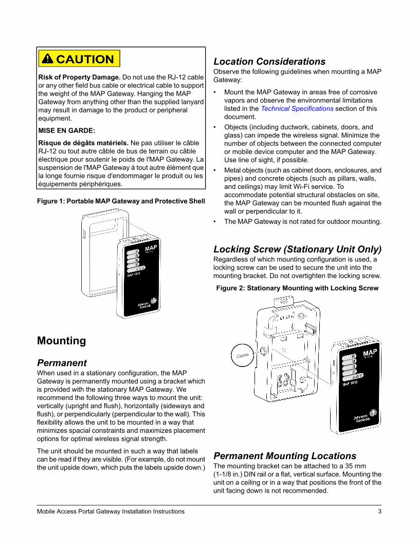
Locking Screw (Stationary Unit Only)Regardless of which mounting configuration is used, alocking screw can be used to secure the unit into themounting bracket. Do not overtighten the locking screw.
Figure 2: Stationary Mounting with Locking Screw
Permanent Mounting LocationsThe mounting bracket can be attached to a 35 mm(1-1/8 in.) DIN rail or a flat, vertical surface. Mounting theunit on a ceiling or in a way that positions the front of theunit facing down is not recommended.
Although the bracket has two mounting clips, only thebottom clip snaps inward. The top clip is permanentlylocked in the outward position, and it can be used as anadditional hole for screwing the bracket into place. If notutilized for DIN rail or surface mounting, the top andbottom clips may be removed from the mounting bracket.
DIN Rail Mounting
To mount the bracket on a DIN rail:
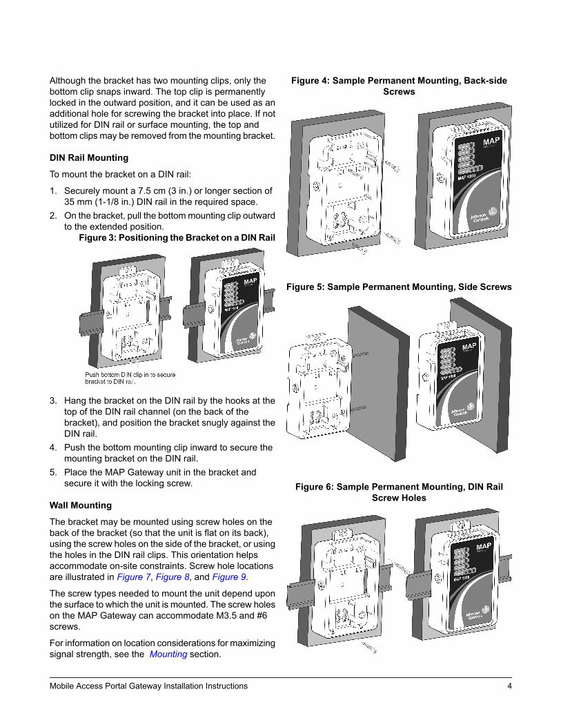
1. Securely mount a 7.5 cm (3 in.) or longer section of35 mm (1-1/8 in.) DIN rail in the required space.
2. On the bracket, pull the bottommounting clip outwardto the extended position.
Figure 3: Positioning the Bracket on a DIN Rail
3. Hang the bracket on the DIN rail by the hooks at thetop of the DIN rail channel (on the back of thebracket), and position the bracket snugly against theDIN rail.
4. Push the bottom mounting clip inward to secure themounting bracket on the DIN rail.
5. Place the MAP Gateway unit in the bracket andsecure it with the locking screw.
Wall Mounting
The bracket may be mounted using screw holes on theback of the bracket (so that the unit is flat on its back),using the screw holes on the side of the bracket, or usingthe holes in the DIN rail clips. This orientation helpsaccommodate on-site constraints. Screw hole locationsare illustrated in Figure 7, Figure 8, and Figure 9.
The screw types needed to mount the unit depend uponthe surface to which the unit is mounted. The screw holeson the MAP Gateway can accommodate M3.5 and #6screws.
For information on location considerations for maximizingsignal strength, see the Mounting section.
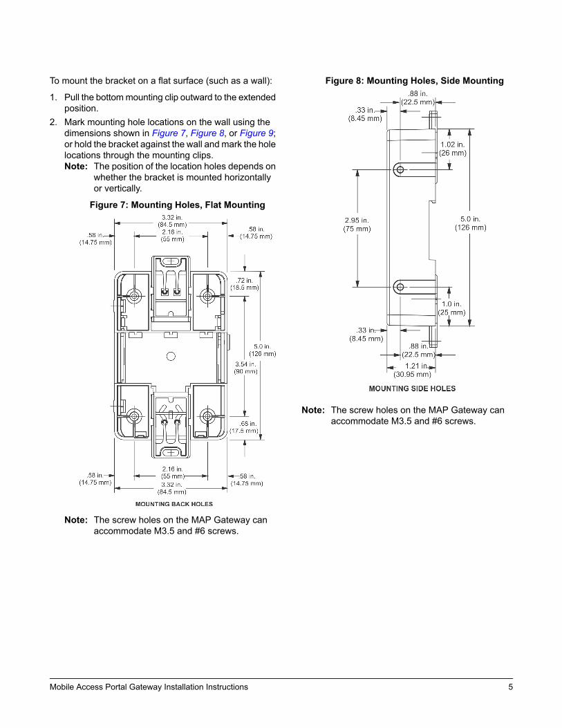
To mount the bracket on a flat surface (such as a wall):
1. Pull the bottommounting clip outward to the extendedposition.
2. Mark mounting hole locations on the wall using thedimensions shown in Figure 7, Figure 8, or Figure 9;or hold the bracket against the wall and mark the holelocations through the mounting clips.Note: The position of the location holes depends on
whether the bracket is mounted horizontallyor vertically.
Figure 7: Mounting Holes, Flat Mounting
Note: The screw holes on the MAP Gateway canaccommodate M3.5 and #6 screws.
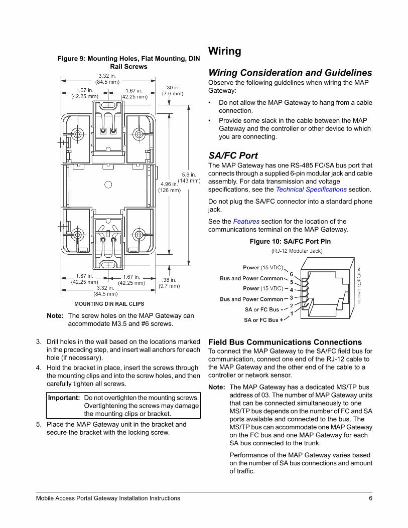
Figure 8: Mounting Holes, Side Mounting
Note: The screw holes on the MAP Gateway canaccommodate M3.5 and #6 screws.
Note: The screw holes on the MAP Gateway canaccommodate M3.5 and #6 screws.
3. Drill holes in the wall based on the locations markedin the preceding step, and insert wall anchors for eachhole (if necessary).
4. Hold the bracket in place, insert the screws throughthe mounting clips and into the screw holes, and thencarefully tighten all screws.
Important: Do not overtighten themounting screws.Overtightening the screwsmay damagethe mounting clips or bracket.
5. Place the MAP Gateway unit in the bracket andsecure the bracket with the locking screw.
Wiring
Wiring Consideration and GuidelinesObserve the following guidelines when wiring the MAPGateway:
• Do not allow the MAP Gateway to hang from a cableconnection.
• Provide some slack in the cable between the MAPGateway and the controller or other device to whichyou are connecting.
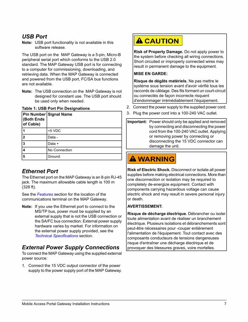
SA/FC PortThe MAP Gateway has one RS-485 FC/SA bus port thatconnects through a supplied 6-pin modular jack and cableassembly. For data transmission and voltagespecifications, see the Technical Specifications section.
Do not plug the SA/FC connector into a standard phonejack.
See the Features section for the location of thecommunications terminal on the MAP Gateway.
Figure 10: SA/FC Port Pin
Field Bus Communications ConnectionsTo connect the MAP Gateway to the SA/FC field bus forcommunication, connect one end of the RJ-12 cable tothe MAP Gateway and the other end of the cable to acontroller or network sensor.
Note: The MAP Gateway has a dedicated MS/TP busaddress of 03. The number of MAPGateway unitsthat can be connected simultaneously to oneMS/TP bus depends on the number of FC and SAports available and connected to the bus. TheMS/TP bus can accommodate oneMAPGatewayon the FC bus and one MAP Gateway for eachSA bus connected to the trunk.
Performance of the MAP Gateway varies basedon the number of SA bus connections and amountof traffic.
USB PortNote: USB port functionality is not available in this
software release.
The USB port on the MAP Gateway is a 5-pin, Micro-Bperipheral serial port which conforms to the USB 2.0standard. The MAP Gateway USB port is for connectingto a computer for commissioning, downloading, andretrieving data. When the MAP Gateway is connectedand powered from the USB port, FC/SA bus functionsare not available.
Note: The USB connection on the MAP Gateway is notdesigned for constant use. The USB port shouldbe used only when needed.
Table 1: USB Port Pin DesignationsSignal NamePin Number
(Both Endsof Cable)
+5 VDC1
Data -2
Data +3
No Connection4
Ground5
Ethernet PortThe Ethernet port on the MAPGateway is an 8-pin RJ-45jack. The maximum allowable cable length is 100 m(328 ft).
See the Features section for the location of thecommunications terminal on the MAP Gateway.
Note: If you use the Ethernet port to connect to theMS/TP bus, power must be supplied by anexternal supply that is not the USB connection orthe SA/FC bus connection. External power supplyhardware varies by market. For information onthe external power supply provided, see theTechnical Specifications section.
External Power Supply ConnectionsTo connect the MAPGateway using the supplied externalpower source:
1. Connect the 15 VDC output connector of the powersupply to the power supply port of the MAP Gateway.
Risk of Property Damage. Do not apply power tothe system before checking all wiring connections.Short circuited or improperly connected wires mayresult in permanent damage to the equipment.
MISE EN GARDE:
Risque de dégâts matériels. Ne pas mettre lesystème sous tension avant d'avoir vérifié tous lesraccords de câblage. Des fils formant un court-circuitou connectés de façon incorrecte risquentd'endommager irrémédiablement l'équipement.
2. Connect the power supply to the supplied power cord.3. Plug the power cord into a 100-240 VAC outlet.
Important: Power should only be applied and removedby connecting and disconnecting the powercord from the 100-240 VAC outlet. Applyingor removing power by connecting ordisconnecting the 15 VDC connector candamage the unit.
Risk of Electric Shock. Disconnect or isolate all powersupplies before making electrical connections. More thanone disconnection or isolation may be required tocompletely de-energize equipment. Contact withcomponents carrying hazardous voltage can causeelectric shock and may result in severe personal injuryor death.
AVERTISSEMENT:
Risque de décharge électrique. Débrancher ou isolertoute alimentation avant de réaliser un branchementélectrique. Plusieurs isolations et débranchements sontpeut-être nécessaires pour -couper entièrementl'alimentation de l'équipement. Tout contact avec descomposants conducteurs de tensions dangereusesrisque d'entraîner une décharge électrique et deprovoquer des blessures graves, voire mortelles.
Figure 11: MAPGateway with Sample External PowerSupply
Operation
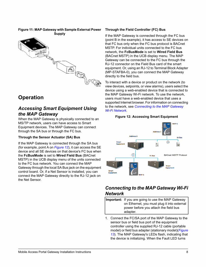
Accessing Smart Equipment Usingthe MAP GatewayWhen the MAP Gateway is physically connected to anMS/TP network, users can have access to SmartEquipment devices. The MAP Gateway can connectthrough the SA bus or through the FC bus.
Through the Sensor Actuator (SA) Bus
If the MAP Gateway is connected through the SA bus(for example, point A on Figure 12), it can access the SEdevice and all SE devices on that device's FC bus whenthe FcBusMode is set toWired Field Bus (BACnetMSTP) in the UCB display menu of the units connectedto the FC bus network. You can connect the MAPGateway through the local SA Bus jack on the equipmentcontrol board. Or, if a Net Sensor is installed, you canconnect the MAP Gateway directly to the RJ-12 jack onthe Net Sensor.
Through the Field Controller (FC) Bus
If the MAP Gateway is connected through the FC bus(point B in the example), it has access to SE devices onthat FC bus only when the FC bus protocol is BACnetMSTP. For individual units connected to the FC busnetwork, the FcBusMode is set toWired Field Bus(BACnet MSTP) in the UCB display menu. The MAPGateway can be connected to the FC bus through theRJ-12 connector on the Field Bus card of the smartequipment. Or, using an RJ-12 to Terminal Block Adapter(MP-STAFBA-0), you can connect the MAP Gatewaydirectly to the field bus.
To interact with a device or product on the network (toview devices, setpoints, or view alarms), users select thedevice using a web-enabled device that is connected tothe MAP Gateway Wi-Fi network. To use the network,users must have a web-enabled device that uses asupported Internet browser. For information on connectingto the network, see Connecting to the MAP GatewayWi-Fi Network.
Figure 12: Accessing Smart Equipment
Connecting to theMAPGatewayWi-FiNetworkImportant: If you are going to use the MAP Gateway
on Ethernet, you must plug it into externalpower before you attach the field busadapter.
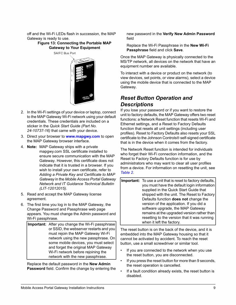
1. Connect the FC/SA port of the MAP Gateway to thesensor bus or field bus port of the equipmentcontroller using the supplied RJ-12 cable (portablemodel) or field bus adapter (stationary model)(Figure13). The MAP Gateway's LEDs flash, indicating thatthe device is initializing. When the Fault LED turns
off and the Wi-Fi LEDs flash in succession, the MAPGateway is ready to use.
Figure 13: Connecting the Portable MAPGateway to Your Equipment
2. In theWi-Fi settings of your device or laptop, connectto the MAPGatewayWi-Fi network using your defaultcredentials. These credentials are included on asticker in the Quick Start Guide (Part No.24-10737-16) that came with your device.
3. Direct your browser to www.mapgwy.com to openthe MAP Gateway browser interface.
4. Note: MAP Gateway ships with a privatemapgwy.com SSL certificate installed toensure secure communication with the MAPGateway. However, this certificate does notindicate that it is trusted in a browser. If youwish to install your own certificate, refer toAdding a Private Key and Certificate to MAPGateway in theMobile Access Portal GatewayNetwork and IT Guidance Technical Bulletin(LIT-12012015).
5. Read and accept the MAP Gateway licenseagreement.
6. The first time you log in to the MAP Gateway, theChange Password and Passphrase web pageappears. You must change the Admin password andWi-Fi passphrase.Important: After you change the Wi-Fi passphrase
or SSID, the webserver restarts and youmust rejoin the MAP Gateway Wi-Finetwork using the new passphrase. Onsome mobile devices, you must selectand forget the original MAP GatewayWi-Fi network before rejoining thenetwork with the new passphrase.
Replace the default password in the New AdminPassword field. Confirm the change by entering the
new password in the Verify New Admin Passwordfield
Replace the Wi-Fi Passphrase in the New Wi-FiPassphrase field and click Save.
Once the MAP Gateway is physically connected to theMS/TP network, all devices on the network that have anequipment number are available.
To interact with a device or product on the network (toview devices, set points, or view alarms), select a deviceusing the mobile device that is connected to the MAPGateway.
Reset Button Operation andDescriptionsIf you lose your password or if you want to restore theunit to factory defaults, the MAPGateway offers two resetfunctions: a Network Reset function that resets Wi-Fi andEthernet settings, and a Reset to Factory Defaultsfunction that resets all unit settings (including userprofiles). Reset to Factory Defaults also resets your SSLcertificate to the Johnson Controls® self-signed certificatethat is in the device when it comes from the factory.
The Network Reset function is intended for individualswho forget their Wi-Fi connection information, and theReset to Factory Defaults function is for use byadministrators who may want to clear all user profilesfrom a device. For information on resetting the unit, seeTable 2.
Important: To use a unit that is reset to factory defaults,you must have the default login informationsupplied in the Quick Start Guide thatshipped with the unit. The Reset to FactoryDefaults function does not change theversion of the application. If you did asoftware upgrade, the MAP Gatewayremains at the upgraded version rather thanresetting to the version that it was runningwhen it left the factory.
The reset button is on the back of the device, and it isembedded into the MAP Gateway housing so that itcannot be activated by accident. To reach the resetbutton, use a small screwdriver or similar tool.
• If you are connected to the network when you usethe reset button, you are disconnected.
• If you press the reset button for more than 9 seconds,the reset operation is cancelled.
• If a fault condition already exists, the reset button isdisabled.
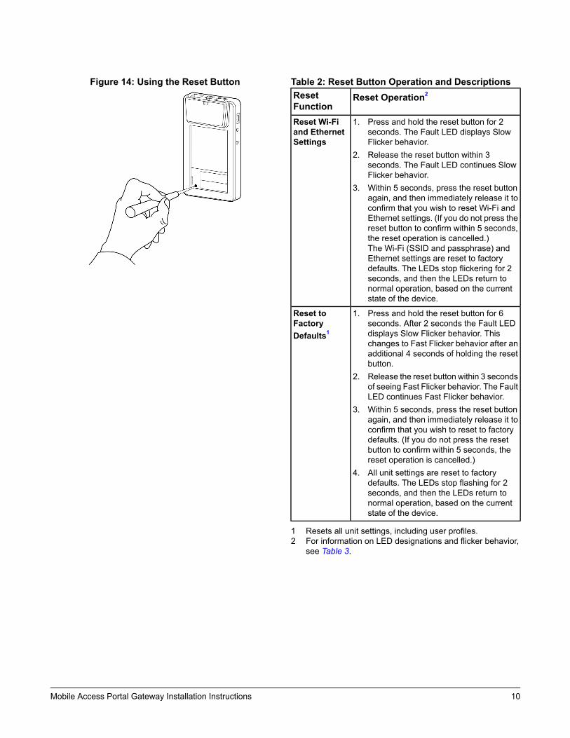
Figure 14: Using the Reset Button Table 2: Reset Button Operation and DescriptionsReset Operation2Reset
Function1. Press and hold the reset button for 2
seconds. The Fault LED displays SlowFlicker behavior.
2. Release the reset button within 3seconds. The Fault LED continues SlowFlicker behavior.
3. Within 5 seconds, press the reset buttonagain, and then immediately release it toconfirm that you wish to reset Wi-Fi andEthernet settings. (If you do not press thereset button to confirm within 5 seconds,the reset operation is cancelled.)The Wi-Fi (SSID and passphrase) andEthernet settings are reset to factorydefaults. The LEDs stop flickering for 2seconds, and then the LEDs return tonormal operation, based on the currentstate of the device.
Reset Wi-Fiand EthernetSettings
1. Press and hold the reset button for 6seconds. After 2 seconds the Fault LEDdisplays Slow Flicker behavior. Thischanges to Fast Flicker behavior after anadditional 4 seconds of holding the resetbutton.
2. Release the reset button within 3 secondsof seeing Fast Flicker behavior. The FaultLED continues Fast Flicker behavior.
3. Within 5 seconds, press the reset buttonagain, and then immediately release it toconfirm that you wish to reset to factorydefaults. (If you do not press the resetbutton to confirm within 5 seconds, thereset operation is cancelled.)
4. All unit settings are reset to factorydefaults. The LEDs stop flashing for 2seconds, and then the LEDs return tonormal operation, based on the currentstate of the device.
Reset toFactoryDefaults1
1 Resets all unit settings, including user profiles.2 For information on LED designations and flicker behavior,
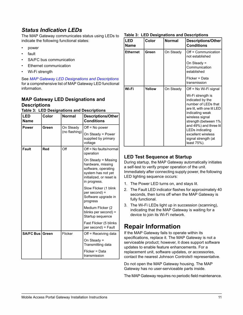
Medium Flicker (2blinks per second) =Startup sequence
Fast Flicker (5 blinksper second) = Fault
OffRedFault
Off = Receiving data
On Steady =Transmitting data
Flicker = Datatransmission
FlickerGreenSA/FCBus
Table 3: LED Designations and DescriptionsDescriptions/OtherConditions
NormalColorLEDName
Off = Communicationnot established
On Steady =Communicationestablished
Flicker = Datatransmission
On SteadyGreenEthernet
Off = No Wi-Fi signal
Wi-Fi strength isindicated by thenumber of LEDs thatare lit, with one lit LEDindicating weakwireless signalstrength (between 1%and 49%) and three litLEDs indicatingexcellent wirelesssignal strength (atleast 75%).
On SteadyYellowWi-Fi
LED Test Sequence at StartupDuring startup, the MAP Gateway automatically initiatesa self-test to verify proper operation of the unit.Immediately after connecting supply power, the followingLED lighting sequence occurs:
1. The Power LED turns on, and stays lit.2. The Fault LED indicator flashes for approximately 40
seconds, then turns off when the MAP Gateway isfully functional.
3. The Wi-Fi LEDs light up in succession (scanning),indicating that the MAP Gateway is waiting for adevice to join its Wi-Fi network.
Repair InformationIf the MAP Gateway fails to operate within itsspecifications, replace it. The MAP Gateway is not aserviceable product; however, it does support softwareupdates to enable feature enhancements. For areplacement unit, software updates, or accessories,contact the nearest Johnson Controls® representative.
Do not open the MAP Gateway housing. The MAPGateway has no user-serviceable parts inside.
TheMAPGateway requires no periodic fieldmaintenance.
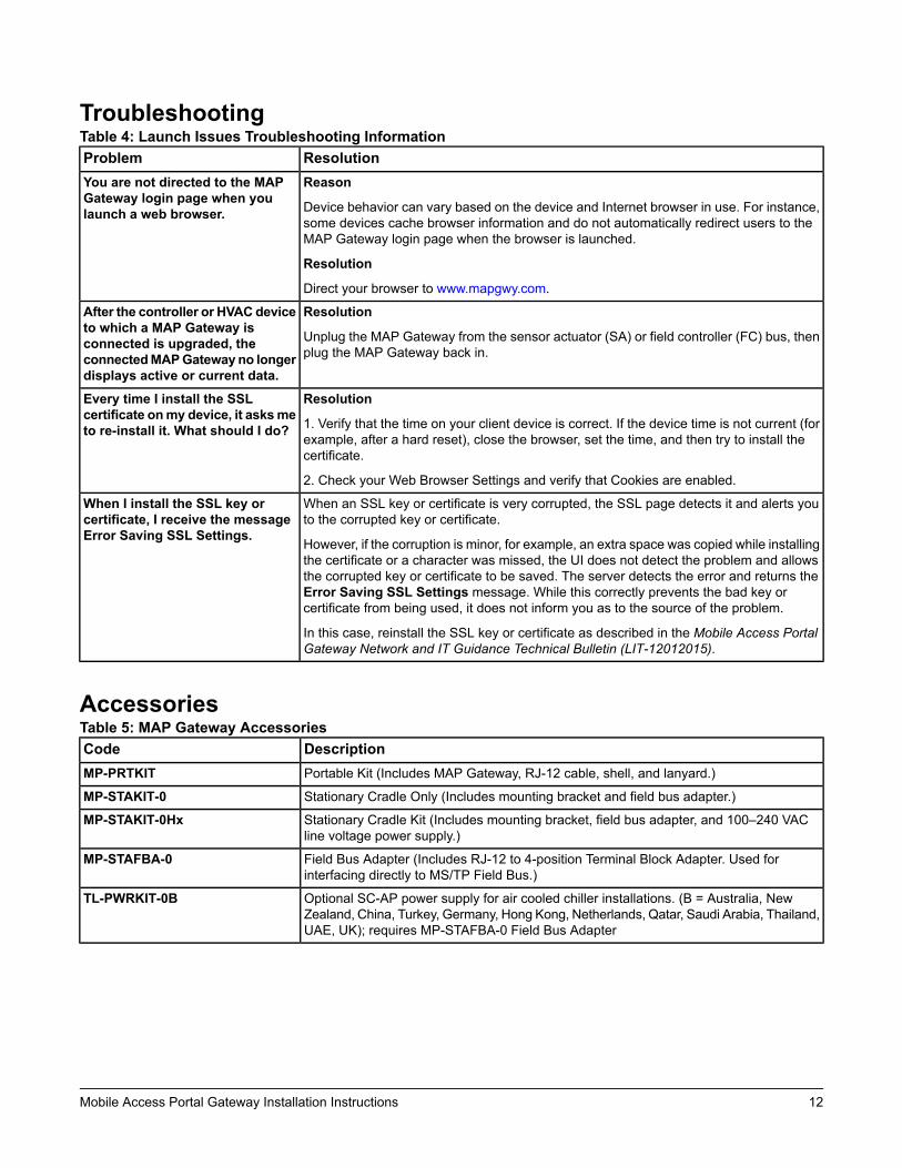
TroubleshootingTable 4: Launch Issues Troubleshooting Information
ResolutionProblemReason
Device behavior can vary based on the device and Internet browser in use. For instance,some devices cache browser information and do not automatically redirect users to theMAP Gateway login page when the browser is launched.
Resolution
Direct your browser to www.mapgwy.com.
You are not directed to the MAPGateway login page when youlaunch a web browser.
Resolution
Unplug the MAP Gateway from the sensor actuator (SA) or field controller (FC) bus, thenplug the MAP Gateway back in.
After the controller or HVACdeviceto which a MAP Gateway isconnected is upgraded, theconnectedMAPGateway no longerdisplays active or current data.
Resolution
1. Verify that the time on your client device is correct. If the device time is not current (forexample, after a hard reset), close the browser, set the time, and then try to install thecertificate.
2. Check your Web Browser Settings and verify that Cookies are enabled.
Every time I install the SSLcertificate onmy device, it asksmeto re-install it. What should I do?
When an SSL key or certificate is very corrupted, the SSL page detects it and alerts youto the corrupted key or certificate.
However, if the corruption is minor, for example, an extra space was copied while installingthe certificate or a character was missed, the UI does not detect the problem and allowsthe corrupted key or certificate to be saved. The server detects the error and returns theError Saving SSL Settings message. While this correctly prevents the bad key orcertificate from being used, it does not inform you as to the source of the problem.
In this case, reinstall the SSL key or certificate as described in the Mobile Access PortalGateway Network and IT Guidance Technical Bulletin (LIT-12012015).
When I install the SSL key orcertificate, I receive the messageError Saving SSL Settings.
AccessoriesTable 5: MAP Gateway Accessories
DescriptionCodePortable Kit (Includes MAP Gateway, RJ-12 cable, shell, and lanyard.)MP-PRTKIT
Stationary Cradle Only (Includes mounting bracket and field bus adapter.)MP-STAKIT-0
Stationary Cradle Kit (Includes mounting bracket, field bus adapter, and 100–240 VACline voltage power supply.)
MP-STAKIT-0Hx
Field Bus Adapter (Includes RJ-12 to 4-position Terminal Block Adapter. Used forinterfacing directly to MS/TP Field Bus.)
MP-STAFBA-0
Optional SC-AP power supply for air cooled chiller installations. (B = Australia, NewZealand, China, Turkey, Germany, Hong Kong, Netherlands, Qatar, Saudi Arabia, Thailand,UAE, UK); requires MP-STAFBA-0 Field Bus Adapter
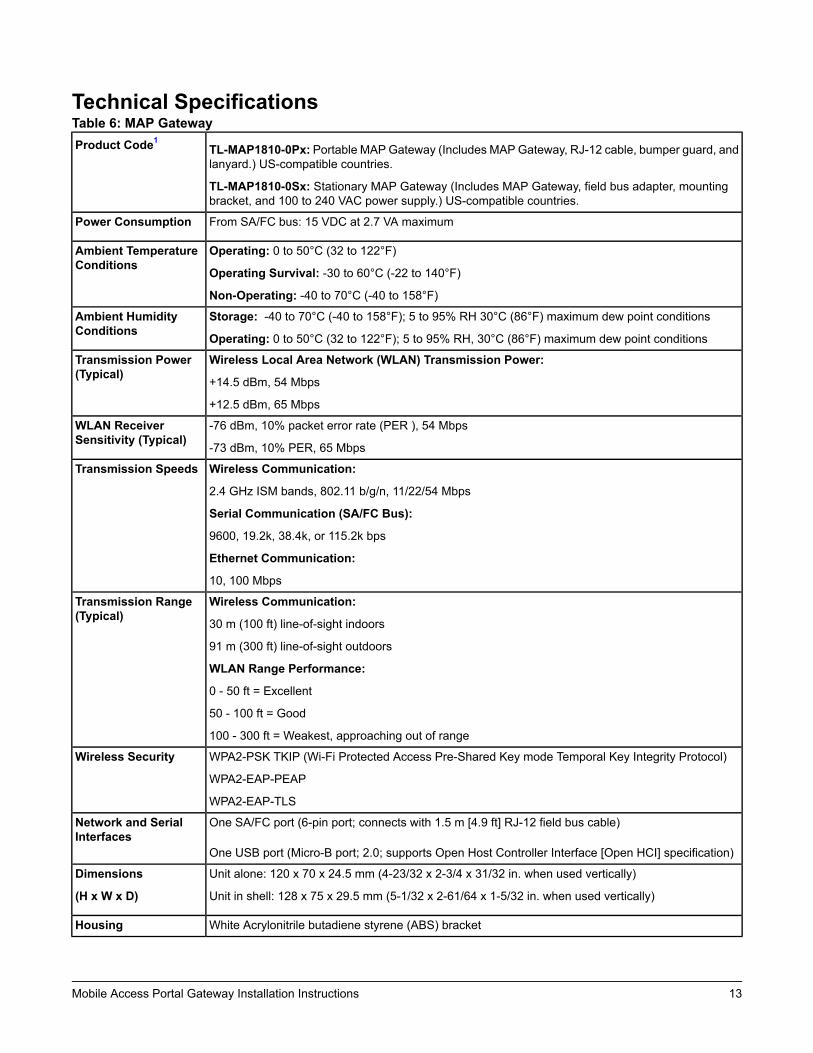
TL-MAP1810-0Sx: Stationary MAP Gateway (Includes MAP Gateway, field bus adapter, mountingbracket, and 100 to 240 VAC power supply.) US-compatible countries.
Product Code1
From SA/FC bus: 15 VDC at 2.7 VA maximumPower Consumption
Operating: 0 to 50°C (32 to 122°F)
Operating Survival: -30 to 60°C (-22 to 140°F)
Non-Operating: -40 to 70°C (-40 to 158°F)
Ambient TemperatureConditions
Storage: -40 to 70°C (-40 to 158°F); 5 to 95% RH 30°C (86°F) maximum dew point conditions
Operating: 0 to 50°C (32 to 122°F); 5 to 95% RH, 30°C (86°F) maximum dew point conditions
Ambient HumidityConditions
Wireless Local Area Network (WLAN) Transmission Power:
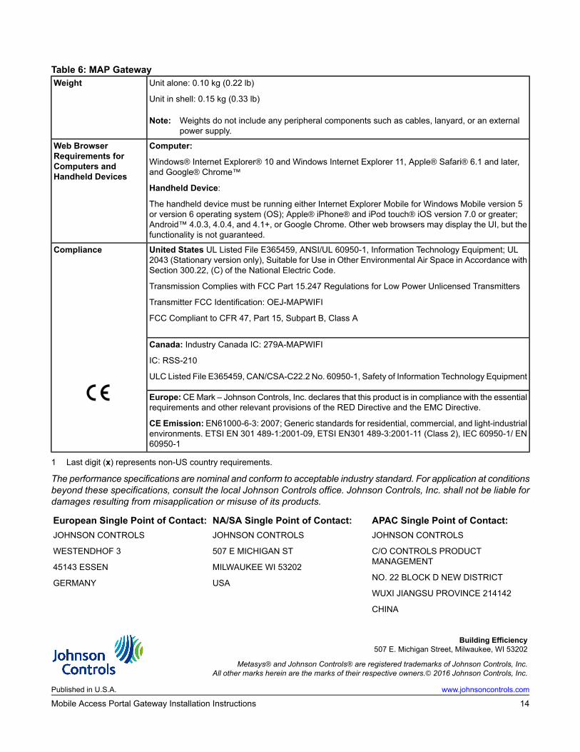
Note: Weights do not include any peripheral components such as cables, lanyard, or an externalpower supply.
Weight
Computer:
Windows® Internet Explorer® 10 and Windows Internet Explorer 11, Apple® Safari® 6.1 and later,and Google® Chrome™
Handheld Device:
The handheld device must be running either Internet Explorer Mobile for Windows Mobile version 5or version 6 operating system (OS); Apple® iPhone® and iPod touch® iOS version 7.0 or greater;Android™ 4.0.3, 4.0.4, and 4.1+, or Google Chrome. Other web browsers may display the UI, but thefunctionality is not guaranteed.
Web BrowserRequirements forComputers andHandheld Devices
United States UL Listed File E365459, ANSI/UL 60950-1, Information Technology Equipment; UL2043 (Stationary version only), Suitable for Use in Other Environmental Air Space in Accordance withSection 300.22, (C) of the National Electric Code.
Transmission Complies with FCC Part 15.247 Regulations for Low Power Unlicensed Transmitters
Transmitter FCC Identification: OEJ-MAPWIFI
FCC Compliant to CFR 47, Part 15, Subpart B, Class A
Compliance
Canada: Industry Canada IC: 279A-MAPWIFI
IC: RSS-210
ULC Listed File E365459, CAN/CSA-C22.2 No. 60950-1, Safety of Information Technology Equipment
Europe:CEMark – Johnson Controls, Inc. declares that this product is in compliance with the essentialrequirements and other relevant provisions of the RED Directive and the EMC Directive.
CE Emission: EN61000-6-3: 2007; Generic standards for residential, commercial, and light-industrialenvironments. ETSI EN 301 489-1:2001-09, ETSI EN301 489-3:2001-11 (Class 2), IEC 60950-1/ EN60950-1
1 Last digit (x) represents non-US country requirements.
The performance specifications are nominal and conform to acceptable industry standard. For application at conditionsbeyond these specifications, consult the local Johnson Controls office. Johnson Controls, Inc. shall not be liable fordamages resulting from misapplication or misuse of its products.
APAC Single Point of Contact:NA/SA Single Point of Contact:European Single Point of Contact:JOHNSON CONTROLS
C/O CONTROLS PRODUCTMANAGEMENT
NO. 22 BLOCK D NEW DISTRICT
WUXI JIANGSU PROVINCE 214142
CHINA
JOHNSON CONTROLS
507 E MICHIGAN ST
MILWAUKEE WI 53202
USA
JOHNSON CONTROLS
WESTENDHOF 3
45143 ESSEN
GERMANY
Building Efficiency507 E. Michigan Street, Milwaukee, WI 53202