5
Instruction Manual MJ518 Mobile Hydraulic Scissor Lift Table 330 lbs. (150 kg)

Instruction ManualMJ518
Mobile Hydraulic Scissor Lift Table330 lbs. (150 kg)

WARNING!Read this operation manual carefully and understand fully the operating instructions. Improper use of this unit could result in injury.
• DO NOT put foot or hand in scissor mechanism.• Keep neighbouring persons away from the unit when in use.• DO NOT stand in front or behind of lift table when it is in use.• DO NOT crawl under the table.• DO NOT put foot in front of rolling wheels.• DO NOT use lift table on slope or inclined surfaces. • DO NOT lift or ride people on this unit.
CAUTION!• DO NOT move this unit when lifting or lowering the bed or when the bed is in an elevated position. (Bed must be lowered when the unit is running)• DO NOT use this table for any purpose other than it’s intended use and do not load with more than the rated capacity.• DO NOT allow persons to operate this table without complete understanding of its operation.• DO NOT lower the bed too quickly.• During loading/unloading operation, do not release the parking brake.• Load should be distributed on at least 80% of the table area. Stop operation of lift table if load becomes too unstable, do not place objects protruding off edge of the bed.• DO NOT modify lift table without manufacturers written consent.
Daily InspectionDaily inspection of this unit is critical in order to locate any malfunction or fault. Check the following daily before operating your lift table.
1. Check for bending or cracking of the lift table.2. Check for any oil leakage from the cylinder.3. Check for vertical creep of the table.4. Check for smooth movement of the wheels.5. Ensure that brakes are fully functional.6. Ensure that all nuts and bolts are firmly tightened.
Assembly methodThe lift table is packed in a cardboard box. Assembling of the jack up pedal is required.WARNING: Assembly work must be done on a flat surface; wheels must be choked to prevent accidental rolling of the unit.
1. Insert the jack pedal into the pedal pipe and position the tapered side pedal end to right. Tighten the jack pedal using the removed nut and washer with the smallest hex key supplied in the box.

OPERATING THE LIFT TABLE
How to use the brakeThe brake is located next to the swivel caster on right hand side.1. To brake the lift table, press the brake pedal.
2. To release the brake, lift up the brake pedal.
CAUTION: Put lift table in brake mode when stationary in order to prevent sudden movement.
Lifting the TableTo lift the table, press the lifting pedal several times until the table reaches the desired height. The table
lowers slightly after reaching the highest position. Maximum Capacity of this table is 330 lbs. (150kg).WARNING: Do not overload lift table, stay within the rated capacity.Do not load the table on sides or ends only. Load must be distributed on at least 80% of table area.
Lowering the TableWARNING: DO NOT put foot or hand in scissor mechanism. The rotating knob lowers the table.NOTE: The hydraulic cylinder is designed to hold table. As is the nature of the hydraulic system, table lowers very slowly over an extended period of time. Please note that the table does not stay at the same height indefinitely.
Specifications
Model Capacity TableTable
HeightFoot Pedal
Strokes to ElevateWheel Weight
MJ518150 kg.330 lbs.
450 x 700 mm17.7" x 27.5"
220-720 mm8.6" x 28.3"
28100 mm
4"45 kg.99 lbs.
Service InstructionsChange hydraulic oil every 12 monthsLubricate the following areas every month: Fitting of Cylinder/oil, Roller Friction Surface/grease, Link Pin/oil, Pedal Fitting Point/oil, Grease Nipple/grease
Troubleshooting If the table does not lift when pressing lifting pedal several times:
• Adjust the control valve located on the hydraulic cylinder (A) by releasing the set screw and locking nut (B) using a flat screwdriver and a 14mm wrench.• Test the control lever and lifting pedal.
A B
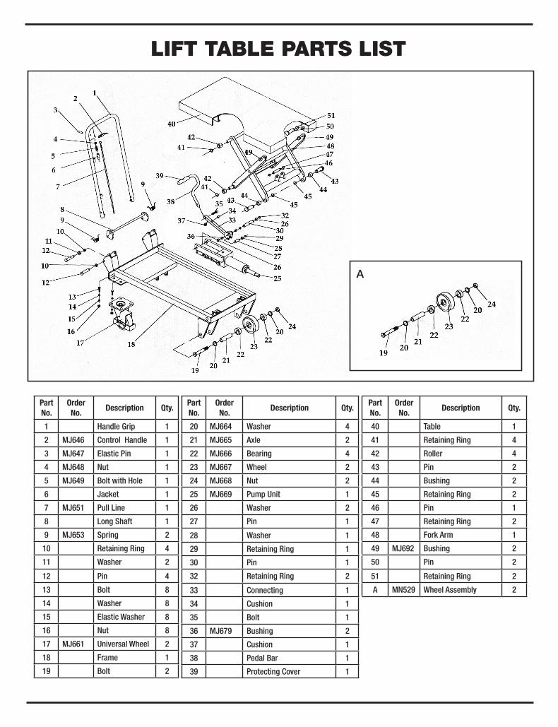
LIFT TABLE PARTS LIST
Part No.
OrderNo.
Description Qty.
1 Handle Grip 1
2 MJ646 Control Handle 1
3 MJ647 Elastic Pin 1
4 MJ648 Nut 1
5 MJ649 Bolt with Hole 1
6 Jacket 1
7 MJ651 Pull Line 1
8 Long Shaft 1
9 MJ653 Spring 2
10 Retaining Ring 4
11 Washer 2
12 Pin 4
13 Bolt 8
14 Washer 8
15 Elastic Washer 8
16 Nut 8
17 MJ661 Universal Wheel 2
18 Frame 1
19 Bolt 2
Part No.
OrderNo.
Description Qty.
20 MJ664 Washer 4
21 MJ665 Axle 2
22 MJ666 Bearing 4
23 MJ667 Wheel 2
24 MJ668 Nut 2
25 MJ669 Pump Unit 1
26 Washer 2
27 Pin 1
28 Washer 1
29 Retaining Ring 1
30 Pin 1
32 Retaining Ring 2
33 Connecting 1
34 Cushion 1
35 Bolt 1
36 MJ679 Bushing 2
37 Cushion 1
38 Pedal Bar 1
39 Protecting Cover 1
PartNo.
OrderNo.
Description Qty.
40 Table 1
41 Retaining Ring 4
42 Roller 4
43 Pin 2
44 Bushing 2
45 Retaining Ring 2
46 Pin 1
47 Retaining Ring 2
48 Fork Arm 1
49 MJ692 Bushing 2
50 Pin 2
51 Retaining Ring 2
A MN529 Wheel Assembly 2
A

HYDRAULIC CYLINDER PARTS LIST
PartNo.
Order No.
Description Qty.
201 MJ699 Seal Washer 1
202 Pump Cylinder 1
203 MJ701 Dust Ring 1
204 MJ702 Y-Seal 1
205 Pump Piston 1
206 Spring 1
207 Spring Cap 1
208 Retaining Ring 1
209 Joint Plate 2
210 Pin 1
211 Pump Body 1
212 Elastic Pin 1
213 Spring 1
214 Strike Pin 1
215 MJ713 Seal Washer 2
216 Axle Sleeve 1
217 MJ715 O-Ring 1
218 Nut 1
219 Screw 1
PartNo.
OrderNo.
Description Qty.
220 Lever Plate 1
221 Nut 1
222 Elastic Washer 1
223 Washer 1
224 Bolt with Hole 1
225 Bolt with Hole 1
226 Nut 1
227 Plug 1
228 MJ726 O-Ring 1
229 Adjusting Bolt 1
230 Spring 1
231 Spindle of Safety Valve 1
232 Steel Ball 1
233 MJ731 O-Ring 1
234 Seat of Pumping Valve 1
235 Spindle of Pumping Valve 1
236 Spring 1
237 Seal Washer 1
238 O-Ring
PartNo.
OrderNo.
Description Qty.
239 MJ737 Seal Washer 1
240 Cylinder 1
241 Housing 1
242 Bolt 1
243 Seal Washer 1
244 Retaining Ring 1
245 Washer 1
246 MJ744 O-Ring 1
247 MJ745 Cup Packing 1
248 Piston 1
249 MJ747 O-Ring 1
250 Piston Rod 1
251 Seal Washer 1
252 Cylinder Cap 1
253 MJ751 O-Ring 1
254 MJ752 Dust Ring 1
255 Plug 1
256 Liquid Throttle Sheath 1
257 Bolt 1


