26
Mobile IPv6 deployment opportunities in next generation 3GPP networks I. Guardini E. Demaria M. La Monaca

Mobile IPv6 deployment opportunities in next generation 3GPP networks
I. GuardiniE. DemariaM. La Monaca

2
Overview of SAE/LTE
• TerminologySAE (System Architecture Evolution): core network/system aspectsLTE (Long Term Evolution): new radio access (E-UTRAN)
• Main system characteristicssupport for packet services onlyOFDM radio technologypeak throughput per user : 100 Mbps DL and 50 Mbps UL (with a 20MHz channel width)multi-access core network: GERAN, UTRAN, E-UTRAN and non-3GPP
• Specifications to be completed by 2008

3
Logical architecture: non roaming
S5 SGi
S4
S3
S1 (CP)
PCRF
S7
S6a
HSS
Rx+
S10
2G/3GSGSN
S11
ServingGateway
S5
Operator IP services(e.g. IMS, PSS, ..)
MME
E-UTRANPDN
Gateway
ePDG
Untrusted non 3GPP IP access
Trusted non 3GPP IP access
HSS
S2a
S2b
S1 (UP)
eNB
eNB
X2
eNB: evolved Node B
MME: Mobility Management Entity (similar to the control part of the SGSN)
PDN GW: access gateway towards Packet Data Networks (similar to the GGSN)
SGi: interface towards Internet/Intranet (equivalent to Gi interface in GPRS)
UTRAN
GERAN
LegacyNetworks

4
Interworking with non 3GPP accesses (I)
• SAE supports both host-based and network-based mobility management solutions
Dual-Stack MIPv6 (host-based)Proxy MIPv6 and MIPv4 in Foreign Agent mode (network-based)
• PDN GW works as MIP/PMIP Home Agentwhen connected to a 3GPP access the UE can be assumed to be at home in MIP sense
mobility within 3GPP accesses (E-UTRAN, UTRAN and GERAN) is managed in a network-based fashion using 3GPP-specific protocols
service continuity is guaranteed in case the UE moves from a 3GPP access to a non 3GPP access (or vice versa)
the UE communicates using the same IP address independently of the access network it is attached to

5
Interworking with non 3GPP accesses (II)
• SAE distinguishes between “trusted” and “untrusted” non 3GPP accesses
• It is up to the operator to decide if a non 3GPP access is trusted or untrusted
the decision is not based just on the access network technology but may depend also on business considerations
• Interworking with an untrusted access is performed via an evolved PDG (ePDG)
the ePDG is similar to a VPN concentratorthe UE has to establish an IPsec tunnel with the ePDG to access operator’s servicesthe ePDG may implement IP mobility protocols (e.g. PMIPv6)

6
Interworking with non 3GPP accesses (III)
• Interworking with a trusted access is performed using a more lightweight procedure
the UE does not need to establish an IPsec tunnel with the ePDG in advanceMIP or PMIP protocols can be used directly between the non 3GPP access network and the SAE core network
the non 3GPP access gateway (e.g. ASN GW in case of mobile WiMAX) can run PMIPv6

7
Interworking with non 3GPP accesses (IV)
SGi
S7
HSS
Rx+S4
S3
S1 (CP)
S10
2G/3GSGSN
S11
MME
S1 (UP)
E-UTRAN
S6a
ServingGateway
Operator IP services(e.g. IMS, PSS, ..)
S2a
S2b
UE
S2c3GPP AAA
Server
Wa*
Ta*
Wm*
S6c
Wx*PCRF
PDNGateway
ePDG
Untrusted non 3GPP IP access(network-based)
Trusted non 3GPP IP access(network-based)
HSS
HAHA
Trusted/untrusted non 3GPP
(host-based)

8
Protocols on non 3GPP interfaces
• The protocols that have been selected for mobility between 3GPP and non 3GPP accesses are
S2a reference point (trusted non 3GPP accesses): Proxy Mobile IPv6 and Mobile IPv4 in Foreign Agent mode
Mobile IPv4 in FA mode was requested by CDMA2000 operators (e.g. Verizon), that want to re-use their already deployed Mobile IPv4 infrastructure
S2b reference point (untrusted non 3GPP accesses): Proxy Mobile IPv6 with dual-stack extensionsS2c reference point (host-based mobility on trusted/untrusted accesses): Dual-Stack Mobile IPv6 (DSMIPv6)
the usage of Mobile IPv4 in co-located mode is still under consideration

9
Interworking scenarios: non roaming
ServingGW
PDNGW
3GPPaccess
Trustednon 3GPP
Untrustednon 3GPP
ePDG
UE
S2a S2b
SGiS5
S1u, S4,S11
Proxy Mobile IPv6or MIPv4 in FA mode
ServingGW
3GPPaccess
Trustednon 3GPP
Untrustednon 3GPP
ePDG
UE
S2c S2c
SGiS5
S1u, S4,S11
PDNGW
Dual-StackMobile IPv6
Network-basedMobility
Host-basedMobility

10
Interworking scenarios: roaming (I)
ServingGW
PDNGW
3GPPaccess
ServingGW
Trustednon 3GPP
Untrustednon 3GPP
ePDG
3GPPaccess
HPLMN
VPLMN
UE
S2aS2b
S1u, S4,S11
S8b
SGiS5
S1u, S4,S11
ProxyMobile IPv6
ServingGW
PDNGW
3GPPaccess
ServingGW
Trustednon 3GPP
Untrustednon 3GPP
ePDG
3GPPaccess
HPLMN
VPLMN
UE
S2a S2b
S1u, S4,S11
S8a/b
SGiS5
S1u, S4,S11
GTP or ProxyMobile IPv6
PMIPv6 orMIPv4 in FA mode
Network-basedMobility
Proxy Mobile IPv6
11
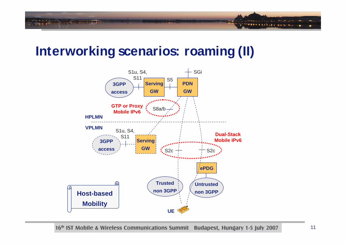
Interworking scenarios: roaming (II)
ServingGW
3GPPaccess
ServingGW
Trustednon 3GPP
Untrustednon 3GPP
ePDG
3GPPaccess
HPLMN
VPLMN
UE
S2c S2c
S1u, S4,S11
S8a/b
SGiS5
S1u, S4,S11
PDNGW
Dual-StackMobile IPv6
GTP or ProxyMobile IPv6
Host-basedMobility

12
Interworking scenarios: roaming (III)
• This scenario has not been officially accepted yet
the Serving GW works as a local mobility anchor and runs PMIPv6 with the PDN GW
the home address is provided by the PDN GW (i.e. the real HA)data traffic is anchored on the PDN GW the Serving GW handles local mobility through DSMIPv6the visited operator can use the Serving GW to enforce policies (e.g. charging)
not clear how to handle Serving GW relocation when the UE moves across VPLMNs
ServingGW
PDNGW
3GPPaccess
Trustednon 3GPP
Untrustednon 3GPP
ePDG
3GPPaccess
HPLMN
VPLMN
UE
S1u, S4,S11
S8b
SGiS5
S1u, S4,S11
ProxyMobile IPv6
ServingGW
S2cS2c
Host-basedMobility

13
PMIPv6/MIPv6: summary of usage scenarios
PDNGW
ServingGW
AccessGW PMIPv6PMIPv6
SGi
PDNGW
ServingGW PMIPv6DSMIPv6
SGi
PDNGW
AccessGW PMIPv6
SGi
PDNGWDSMIPv6
SGi
Roaming andnon roaming
Roaming
(S2a/b)
(S2c)
(S8b)
(S8b)
(S2a/b)
(S2c)
Cascade of PMIPv6 tunnels
Cascade of DSMIPv6 and PMIPv6 tunnels
Non 3GPPAccesses

14
Roaming with or without local anchor• Option A: no local anchor
HPLMN has to interface via PMIPv6 with all non 3GPP AGWsin VPLMNcomplicates the establishment and maintenance of roaming agreements
• Option B: local anchorPDN GW in HPLMN needs to interface via PMIPv6 just with the anchor point in VPLMNsimplifies the establishment of roaming agreementsthe visited operator can exploit the local anchor to enforce policies on UE’s data traffic
PDNGW
Non 3GPPAGWs
BSs
HPLMN VPLMN
PMIPv6 (S2a)
PDNGW
Non 3GPPAGWs
BSs
HPLMN VPLMN
ServingGW
PMIPv6 (S8b)
PMIPv6 (S2a)
No local anchorA
Local anchorB

15
Attach over S2a: trusted non 3GPP access (I)

16
Attach over S2a: trusted non 3GPP access (II)
• Step by step description of the procedure1. The initial Non-3GPP access specific L2 procedures are performed2. The EAP authentication procedure for network access is performed
involving the UE, trusted non-3GPP IP Access and the 3GPP AAA Server. In the roaming case, there may be several AAA proxies involved. The PDN GW information is returned as part of the reply from the 3GPP AAA Server to the MAG in the trusted non-3GPP access
3. After successful authentication and authorization, the L3 attachprocedure is triggered
4. MAG function of Trusted Non-3GPP IP Access sends Proxy Binding Update message to PDN GW
5. The selected PDN GW informs the 3GPP AAA Server of its address

17
Attach over S2a: trusted non 3GPP access (III)
• Step by step description of the procedure (cont’ed)6. The PDN GW processes the proxy binding update and creates a
binding cache entry for the UE. The PDN GW allocates IP address for the UE. The PDN GW then sends a proxy binding acknowledgement to the MAG function in Trusted Non-3GPP IP Access, including the IP address(es) allocated for the UE
7. The PMIPv6 tunnel is set up between the Trusted Non-3GPP IP Access and the PDN GW
8. L3 attach procedure is completed. IP connectivity between the UEand the PDN GW is set for uplink and downlink directions

18
Attach over S2b: untrusted non 3GPP access
UE ePDG PDN GW
1
2
4
5
6
7
IKEv2 (IP Address Configuration)
IPsec Tunnel
HSS/AAA
Proxy BU (MN-ID, IP addr Req)
Proxy Binding Ack(IP addr)
PMIP Tunnel
IKEv2 authentication and tunnel setup Authentication and Authorization
IPsec tunnel setup completion
3 Update PDN GW Address

19
Attach over S2b/S8b: cascade of tunnels (I)UE ePDG Serving GW
1
2
3
5
6
7
HSS/AAA
Proxy BU (MN-ID, IP Addr Request )
Proxy Binding Ack(IP Addr
Proxy BU ( MN-ID,IP Addr Req)
Proxy Binding AckIP Addr)
3GPP AAA Proxy
IKE_AUTH Authentication Authentication and Authorization Authentication and Authorization
IPsec tunnel setup completion
IKEv2 (IP Address Configuration)8
9
PDN GW
PMIP Tunnel PMIP TunnelIPsec Tunnel
4 Update PDN GWAddress

20
Attach over S2b/S8b: cascade of tunnels (II)
• Step by step description of the procedure1. The IKEv2 tunnel establishment procedure is started by the UE. The
ePDG IP address to which the UE needs to form IPsec tunnel is discovered via DNS query. The PDN GW information is returned as part of the reply from the 3GPP AAA Proxy to the ePDG. This may entail an additional name resolution step, issuing a request to a DNS Server
2. The ePDG sends the PBU message to the Serving GW3. The visited Serving GW processes the proxy binding update and
creates a binding cache entry for the UE. Then the visited Serving GW sends the PBU message to the PDN GW using its own address as the MAG address. Note that the binding cache entry on the Serving GW does not yet have the UE’s IP address information. This information will be added to the binding cache entry after step 4

21
Attach over S2b/S8b: cascade of tunnels (III)
• Step by step description of the procedure (cont’ed)4. The selected PDN GW informs the 3GPP AAA Server of its address5. The PDN GW processes the proxy binding update and creates a
binding cache entry for the UE. The PDN GW allocates an IP address for the UE. The PDN GW then sends a proxy binding ack to the Serving GW, including the IP address allocated for the UE. Once the Serving GW processes the proxy Binding Ack, it stores the UE’s IP address information in the binding cache entry
6. After the Proxy BU/Proxy BAck is successful, there is a PMIPv6 tunnel setup between the Serving GW and the PDN GW
7. The ePDG continues with the IKE_AUTH exchange
22
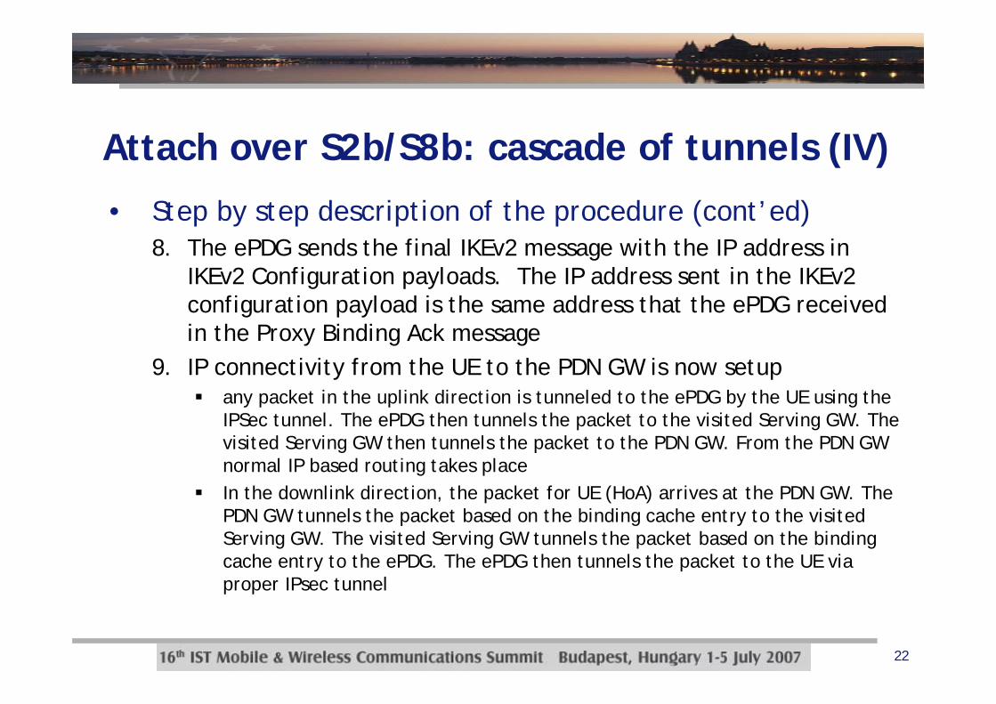
Attach over S2b/S8b: cascade of tunnels (IV)
• Step by step description of the procedure (cont’ed)8. The ePDG sends the final IKEv2 message with the IP address in
IKEv2 Configuration payloads. The IP address sent in the IKEv2 configuration payload is the same address that the ePDG received in the Proxy Binding Ack message
9. IP connectivity from the UE to the PDN GW is now setupany packet in the uplink direction is tunneled to the ePDG by the UE using the IPSec tunnel. The ePDG then tunnels the packet to the visited Serving GW. The visited Serving GW then tunnels the packet to the PDN GW. From the PDN GW normal IP based routing takes placeIn the downlink direction, the packet for UE (HoA) arrives at the PDN GW. The PDN GW tunnels the packet based on the binding cache entry to the visited Serving GW. The visited Serving GW tunnels the packet based on the binding cache entry to the ePDG. The ePDG then tunnels the packet to the UE via proper IPsec tunnel

23
PMIPv6: an example scenario (I)
ServingGateway
Operator IP services(e.g. IMS, PSS, ..)PDN
Gateway
ePDG
Untrusted non 3GPP IP access
S2a
S2b
UE E-UTRAN
AGW
MAGMAG
Trusted non 3GPP access
MAGMAG
Data packets HAHA
PBU
PBA
24
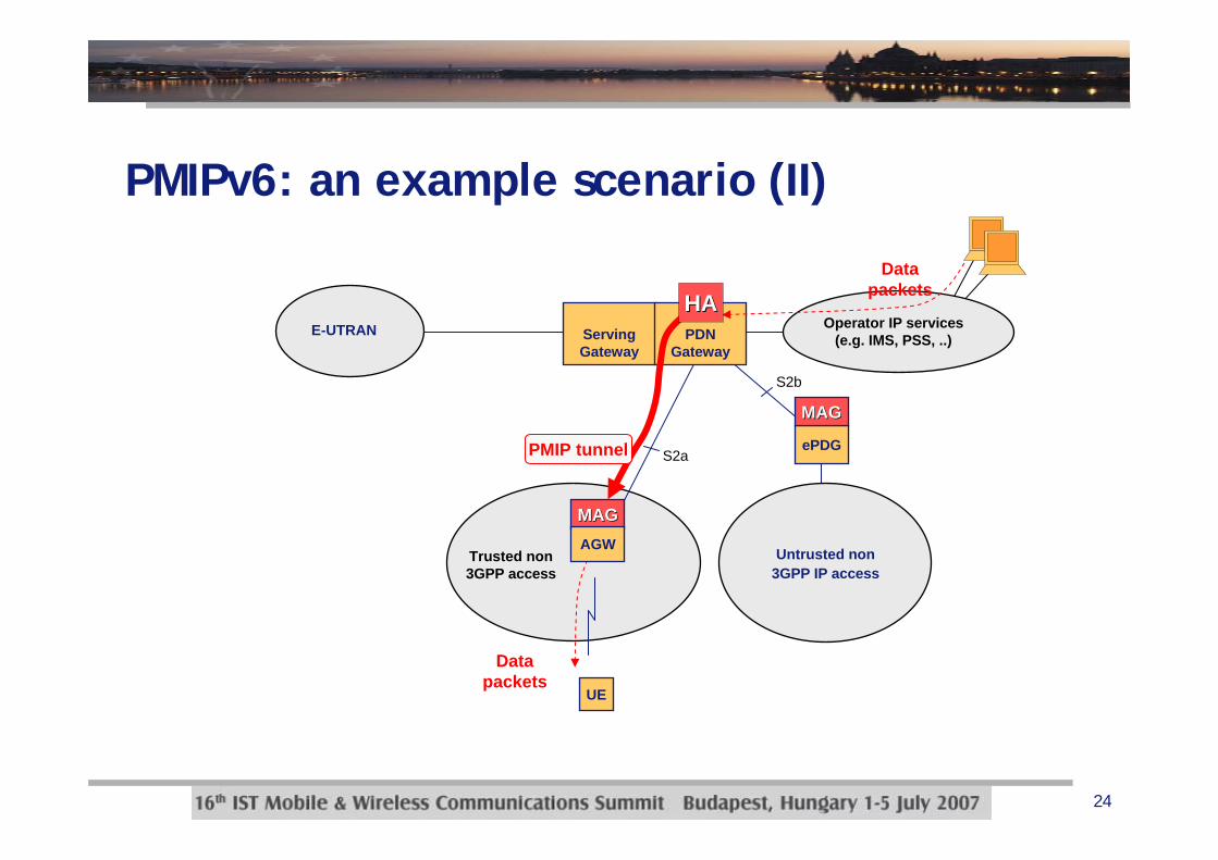
PMIPv6: an example scenario (II)
ServingGateway
Operator IP services(e.g. IMS, PSS, ..)PDN
Gateway
ePDG
Untrusted non 3GPP IP access
S2a
S2b
E-UTRAN
MAGMAG
Trusted non 3GPP access
MAGMAG
Data packets
UE
HAHA
AGW
PMIP tunnel
Data packets

25
PMIPv6 in 3GPP vs. PMIPv6 in IETF
• The PMIPv6 usage scenarios foreseen for 3GPP SAE/LTE present some differences with respect to those in the scope of the IETF MIP6 WG
PMIPv6 is used for inter-system handovers (i.e. handovers between 3GPP and non 3GPP accesses)
PMIPv6 is used as a global mobility protocol
PMIPv6 may be used in roaming scenarios, which means that the HAand the Proxy Mobility Agent may be located in different administrative domainsin the roaming case there is the possibility to have a cascade of PMIPv6 tunnels (AGW – Serving GW, Serving GW – PDN GW)
in this way there is a local anchor point in the visited domain, that can be used by the visited operator to enforce policies on UE’s trafficthe local anchor also simplifies the establishment of roaming agreements

26
Conclusions
• IETF protocols will be extensively used for 3GPP-non-3GPP mobility in UMTS Rel8
PMIPv6, DSMIPv6 and MIPv4 in FA mode
• Some open issues still need to be resolved/clarifiedmobility mode selection (PMIPv6, DSMIPv6 and MIPv4 in FA mode)multihoming (i.e. multiple interface) managementsimultaneous usage of multiple access technologies for load-sharing or performance optimizationcombined usage of PMIPv6 and DSMIPv6 in case the UE moves into an access network that does not support any mobility feature (e.g. domestic/public WiFi access)handover optimizations for tight interworking with mobile WiMAXand/or CDMA2000


