SSP 42004 Revision E National Aeronautics and Space Administration International Space Station Program Johnson Space Center Houston, Texas Contract No. NAS15–10000 International Space Station Program Revision E, May 22, 1997 Type 1 Approved by NASA Mobile Servicing System (MSS) to User (Generic) Interface Control Document Part I
Transcript
SSP 42004 Revision E
National Aeronautics and Space AdministrationInternational Space Station ProgramJohnson Space CenterHouston, TexasContract No. NAS15–10000
International Space Station Program
Revision E,
May 22, 1997
Type 1Approved by NASA
Mobile Servicing System (MSS) to User(Generic)
Interface Control DocumentPart I
SSP 42004, Part 1, Revision E May 22, 1997
REVISION AND HISTORY PAGE
REV. DESCRIPTION PUB.DATE
C Totally revised Space Station Freedom Document into an International Space Station Alpha Document 03–14–94
D Revision D reference PIRNs 42004–CS–0004A, 42004–NA–0002, 42004–NA–0003, TBD42004–NA–0004, 42004–NA–0007D, 42004–NA–0008A, 42004–NA–0009C,42004–NA–0010B, 42004–NA–0013A
SSP 42004, Part 1, Revision E May 22, 1997
i
INTERNATIONAL SPACE STATION PROGRAM
MOBILE SERVICING SYSTEM TO USER (GENERIC)
INTERFACE CONTROL DOCUMENT
MAY 22, 1997
CONCURRENCE
PREPARED BY:
CHECKED BY:
SIGNATURE
SUPERVISED BY (NASA):
PRINT NAME ORGN
DATE
SIGNATURE
PRINT NAME ORGN
DATE
SUPERVISED BY (BOEING):
SIGNATURE
PRINT NAME ORGN
DATE
SIGNATURE
PRINT NAME ORGN
DATE
DQA:
SIGNATURE
PRINT NAME ORGN
DATE
SSP 42004, Part 1, Revision E May 22, 1997
ii
NASA/CSA
INTERNATIONAL SPACE STATION PROGRAM
MOBILE SERVICING SYSTEM (MSS) TO USERINTERFACE CONTROL DOCUMENT
MAY 22, 1997
DATE
Print Name
For NASA
DATE
Print Name
For CSA
SSP 42004, Part 1, Revision E May 22, 1997
iii
PREFACE
SSP 42004, Mobile Servicing System (MSS) to User Interface Control Document (ICD)Part I shall be implemented on all new Program contractual and internal activities andshall be included in any existing contracts through contract changes. This document isunder the control of the Space Station Control Board (SSCB) with the concurrence ofCanadian Space Agency (CSA), and any changes or revisions will be approved by theSSCB and CSA.
Program Manager, DateInternational Space Station
SSP 42004, Part 1, Revision E May 22, 1997
iv
INTERNATIONAL SPACE STATION PROGRAM
MOBILE SERVICING SYSTEM TO USER (GENERIC)
INTERFACE CONTROL DOCUMENT PART 1
LIST OF CHANGES
MAY 22, 1997
All changes to paragraphs, tables, and figures in this document are shown below:
I3.1.5–1 FRGF TO USER INTERFACE HARDWARE RESPONSIBILITY I3 – 1. . . . . . . . . . .
SSP 42004, Part 1, Revision E May 22, 1997
1 – 1
1.0 INTRODUCTION
The Space Station provides a Mobile Servicing System (MSS) to assist in the assembly andexternal maintenance of the Space Station. The MSS will be used to service users, transporthardware about the Space Station, and support Extravehicular Activity (EVA) operations.
The flight segments of the MSS consist of the Space Station Remote Manipulator System(SSRMS), Mobile Remote Servicer Base System (MBS), the Special Purpose DexterousManipulator (SPDM), and the MSS Control Equipment (MCE). The Mobile Remote Servicer(MRS) comprises the MBS, and the SSRMS. The Space Station Manned Base (SSMB) MobileTransporter (MT) provides the mobility function for the MBS. The SSRMS and SPDM providethe capabilities to support Space Station assembly, maintenance, servicing, and EVA. Thecontrol equipment consists of hardware and software to control the MSS.
1.1 PURPOSE AND SCOPE
This Interface Control Document (ICD) defines and controls the physical and functionalinterfaces which shall be provided by the Mobile Servicing System (MSS) for users.
Chapter 3 of this ICD is divided into 8 sections (A, B, C, D, E, F, G, & I) as shown in Figure1.1–1. Definition for the Power and Data Grapple Fixture (PDGF) to user interfaces are inSection A. The MRS Base System (MBS) Common Attach System (MCAS) to user interfacesare defined in Section B. The ORU Tool Changeout Mechanism (OTCM) to user interfaces aredefined in Section C. The micro conical interfaces to users are defined in Section D. Theinterfaces between the SPDM ORU Tool Platform (OTP) and the users are defined in Section E.The interfaces between the SPDM tool storage and the user tool holder are defined in Section F.The interface between the SPDM OTCM and user tools shall be as defined in Section G. Theinterface between the FRGF and the generic user including the PWP shall be as defined inSection I.
1.1.1 SECTION A PURPOSE AND SCOPE
This section of the ICD defines and controls the physical, electrical, and functional interfacerequirements between the Power Data Grapple Fixture (PDGF) and a user of the SSRMS, SPDMor MBS Payload/ORU Accommodation (POA). The specific structural, mechanical, andelectrical attachments for the PDGF to the User will be defined in Part II of this ICD.
1.1.2 SECTION B PURPOSE AND SCOPE
This section of the ICD defines and controls the physical, electrical, and functional interfacerequirements between the MBS Common Attach System (MCAS) and a user. The specificstructural, mechanical, and electrical attachments for the MCAS interface to the user will bedefined in Part II of this ICD. The mechanical interface plane is defined between the MCAS(V–guides and the user guide pins, and the MCAS capture latch and user capture bar) and theuser. The electrical interface plane is defined between the MCAS active half of the UmbilicalMechanism Assembly (UMA) and the user passive half of the UMAs.
SSP 42004, Part 1, Revision E May 22, 1997
1 – 2
1.1.3 SECTION C PURPOSE AND SCOPE
This section of the ICD defines and controls the physical and functional interfaces andconstraints between the OTCM and users with Standard Dexterous Grasp Fixtures (SDGFs).This section of the ICD also defines and controls the generic physical and functional interfacesand constraints between the OTCM and the SPDM stabilization points.
1.1.4 SECTION D PURPOSE AND SCOPE
This section of the ICD defines and controls the generic physical and functional interfaces andconstraints between the MCF Tool and users.
1.1.5 SECTION E PURPOSE AND SCOPE
This section of the ICD defines and controls the generic physical and functional interfaces andconstraints between the OTP and the passive Common Structural Interface (CSI).
1.1.6 SECTION F PURPOSE AND SCOPE
This section of the ICD defines and controls the generic physical and functional interfaces andconstraints between the SPDM and tool holsters.
1.1.7 SECTION G PURPOSE AND SCOPE
This section of the ICD defines and controls the generic physical and functional interfaces andconstraints between the SPDM Tools and users.
1.1.8 RESERVED
1.1.9 SECTION I PURPOSE AND SCOPE
This section of the ICD defines and controls the physical, and functional interface requirementsbetween the Flight Releasable Grapple Fixture (FRGF) and a typical user of the SSRMS, SPDMor MBS Payload/ORU Accommodation (POA). The specific structural and mechanicalattachments for the FRGF to the User will be defined in Part II of this ICD.
1.1.10 RESERVED
1.1.11 RESERVED
1.1.12 RESERVED
1.1.13 RESERVED
1.1.14 APPENDIX A PURPOSE & SCOPE
This appendix of the ICD defines and controls the software interfaces between the MSS RWSCEU and the ISS payloads attached to the MSS. The scope of this document is limited to the
SSP 42004, Part 1, Revision E May 22, 1997
1 – 3
software interfaces between CEU and ISS payloads, elements, and devices attached to the MSS.This document does not address software interfaces between the Special Purpose Dexterous Ma-nipulator (SPDM) and ISS payloads, elements, and devices attached directly to the SPDM.
1.2 PRECEDENCE
In the event of conflict between the International Space Station System Specification and thisICD, the requirements in SSP 41000, the International Space Station System Specification shalltake precedence.
1.3 CHANGE AUTHORITY
The responsibility for assuring the definition, control, and implementation of the interfacesidentified in this document is vested with the National Aeronautics and Space Administration(NASA) Space Station Program Office and with the CSA. This document shall be formallyapproved and controlled in accordance with the provisions of SSP 30459, International SpaceStation Interface Control Plan.
1.4 COMMONALITY OF GRAPPLE FIXTURES AND END EFFECTORS (REFERENCEONLY)
1.4.1 TYPES OF GRAPPLE FIXTURES
1.4.1.1 SS GRAPPLE FIXTURES
The type of grapple fixture being developed specifically for Space Station application is thePDGF (defined in this ICD). The PDGF is mechanically compatible with both the NSTSStandard End Effector (SEE) and the Latching End Effector (LEE). The PDGF is electricallycompatible only with LEEs on the SSRMS, SPDM and the POA.
1.4.1.2 NSTS GRAPPLE FIXTURES
The FRGF is mechanically compatible with both the NSTS Standard End Effector (SEE) and theLatching End Effector (LEE) as shown in Table 1.4.1.2–1. The Electrical Flight Grapple Fixture(EFGF) is mechanically and electrically compatible only with the NSTS Special Purpose EndEffector (SPEE) as shown in Table 1.4.1.2–1. Interfaces associated with the SSRMSmanipulating a payload with the FRGF are defined in Section I of this ICD.
1.5 DEFINITION OF THE TERM “USER”
For purposes of this ICD, the term “user” shall be defined as any payload, pallet, or ORUcombination that interfaces with the SSRMS LEE, the SPDM LEE, the POA, the MCAS, theSPDM OTP, or the SPDM manipulators.
SSP 42004, Part 1, Revision E May 22, 1997
1 – 4
MOBILESERVICINGSYSTEM TO
USER (GENERIC)
PDGF TOUSER
Section A
MCAS TOUSER
Section B
ORU/TOOL-PLATFORM
TO USER Section E
OTCM TOUSERS
Section C
MICROCONICAL TO
USERSection D
SPDM TOUSER TOOLHOLSTERSection F
SPDM OTCMTO USERTOOLS
Section G
FRGFTO
USERSection I
FIGURE 1.1–1 MOBILE SERVICING SYSTEM TO USER ICD SECTIONS
SSP 42004, Part 1, Revision E May 22, 1997
1 – 5
TABLE 1.4.1.2–1 NSTS GF COMPATIBILITY
NSTSGF
SEE SPEE LEE
Mechanical Electrical Mechanical Electrical Mechanical ElectricalFRGF X N/A X N/A X N/A
EFGF X N/A X X NO NO
Legend: X CompatibleN/A No electrical connector either on GF or EE.NO Not compatible.
SSP 42004, Part 1, Revision E May 22, 1997
2 – 1
2.0 DOCUMENTS
2.1 APPLICABLE DOCUMENTS
The following documents of the exact date and revision shown form a part of this ICD to theextent specified herein.DOCUMENT NO. TITLE
ANSI Y 14.5M 1982 Dimensioning and Tolerancing
MIL–STD–1553B Digital Time Division Command/Response Multiplex DatabusRev B, Notice 28 Sep 86References A3.2.1.6.1, A3.2.2.6.1, B3.2.1.6.1, B3.2.2.6.1, C3.2.1.6,
3.2.2.6
NSTS–21000–IDD–ISS Shuttle Orbiter/International Space Station Cargo Standard2 May 95 InterfacesReferences I3.2.1.2, I3.2.1.3, I3.2.1.5.1.1, I3.2.1.5.1.2, I3.2.1.5.1.3
SSP 30219 Space Station Reference Coordinate SystemsRev D21 Jan 94References A3.1.2, B3.1.1.1, C3.1.1.1, D3.1.1.1, E3.1.1.1, F3.1.1.1
SSP 30240 Space Station Grounding RequirementsRev B3 Jun 94References A3.2.1.9.1.3, A3.2.2.9.1.3, B3.2.1.8.1.3, B3.2.2.8.1.3
C3.2.1.9.1.3, C3.2.2.9.1.3
SSP 30242 Space Station Cable/Wire Design and Control RequirementsRev C for Electromagnetic Compatibility3 Jun 94References A3.2.1.9.1.5, A3.2.2.9.1.5, B3.2.1.8.1.5, B3.2.2.8.1.5,
C3.2.1.9.1.5, C3.2.2.9.1.5
SSP 30243 Space Station System Requirements for Electro MagneticRev C1 Capability1 Jul 94References A3.2.1.9.1.1, A3.2.1.9.1.6, A3.2.1.9.1.7, A3.2.2.9.1.1,
SSP 30459 International Space Station Alpha Interface Control PlanRev G, R129 Aug 94Reference 1.3
SSP 30482 Electrical Power Specification and Standards: Vol I, ElectricalRev A, CN–001 Performance Specifications1 Jan 94References A3.2.1.5.1, A3.2.2.5.1, Figure A3.2.1.5.1–1, Figure
SSP 50194 Cargo Handling Interface Assembly to User ICDReferences 1.1.5, E3.1, Figure E3.1.1–1
SSQ 21635 General Specifications for Connectors and Accessories,Rev C Electrical, Circular, Miniature, IVA/EVA/Robot Compatible,
Space QualityReferences A3.2.1.4.1, A3.2.2.4.1, C3.2.1.4.1 C3.2.2.4.1
SSP 42004, Part 1, Revision E May 22, 1997
2 – 3
SSQ 21637 General Specification for Connectors and Accessories,Umbilical Interface, Environmental, Space Quality
References B3.2.1.4, B3.2.2.4
SSP 42004, Part 1, Revision E May 22, 1997
3 – 1
3.0 GENERAL
3.1 ENGINEERING UNITS AND TOLERANCES
When identified, dimensions in this document are shown first in the English Inch Pound (IP)system, and then in the metric equivalent Systems International units (SI) shown in parenthesis.Conversion of units shall be in accordance with ASTM E380. Unless otherwise specified, allflight drawing dimensions are in accordance with ANSI–Y–14.5.
SSP 42004, Part 1, Revision E May 22, 1997
A3 – 1
SECTION A3 PDGF TO USER INTERFACES
A3.0 REQUIREMENTS
A3.1 GENERAL
PDGFs are mounted on users to allow their manipulation by the LEEs associated with theSSRMS, the MBS POA, and the SPDM. The PDGF is also mechanically compatible with theNSTS SRMS.
A3.1.1 INTERFACE DESCRIPTION
The PDGFs will interface with the user via mechanical attachments and electrical connections.For users requiring electrical resources, a harness will be provided with the PDGF to supportelectrical connections. The mechanical/structural interface plane is at the mounting bolt holepattern of the PDGF. The electrical interface plane is between the User connectors and thePDGF harness connectors.
A3.1.2 COORDINATE SYSTEMS
The PDGF Coordinate System is defined in Figure A3.1.2–1. The LEE Coordinate System isdefined in Figure A3.1.2–2.
A3.1.3 PDGF INTERFACE FUNCTIONS
The PDGF shall :
A. Support mechanical and structural attachment to the user
B. Provide EVA access to interface attachments and connections
C. Provide an electrical bonding capability to the user
D. Support power, data, and video utility distribution to the user via a harness
A3.1.4 USER INTERFACE FUNCTIONS
The user shall :
A. Support mechanical and structural attachment of the PDGF
B. Provide EVA access to interface attachments and connections
C. Provide an electrical bonding capability to the PDGF
D. Support power, data, and video utility distribution from the PDGF harness
A3.1.5 INTERFACE RESPONSIBILITIES
The interface hardware responsibilities for the PDGF and the user will be as defined in TableA3.1.5–1.
SSP 42004, Part 1, Revision E May 22, 1997
A3 – 2
A3.2 INTERFACE REQUIREMENTS
A3.2.1 PDGF INTERFACE REQUIREMENTS
A3.2.1.1 PDGF ENVELOPES
a) The PDGF envelope shall provide the capability to EVA install and release the PDGF ORUassembly to or from the PDGF mounting ring.
b) The PDGF envelope shall provide the capability to EVA install and release the PDGF harnessto or from the PDGF mating connectors.
c) The EVA maintenance and approach envelopes are defined in Section A3.2.2.1.
A3.2.1.2 PDGF MECHANICAL INTERFACE
a) The PDGF shall provide a mounting ring for the mechanical attachment of the PDGF to theuser.
b) The PDGF mounting ring shall accommodate holes for eight user mounting bolts.
c) The PDGF shall provide a target for SSRMS operations.
d) The PDGF electrical bonding shall be through the mounting ring to the user.
e) The attachment mechanisms shall comply with SSP 50005, International Space Station FlightCrew Standard.
A3.2.1.3 PDGF STRUCTURAL INTERFACE
The PDGF to User interface shall meet all performance requirements while being subject to theMBS POA and SSRMS Tip LEE interface loads as defined in Table A3.2.1.3–1.
A3.2.1.3.1 IMPACT LOADS
During capture of a user payload by the SSRMS/SPDM or berthing a user payload on the POA,the impact load to the PDGF shall be as defined in Figure A3.2.1.3.1–1.
A3.2.1.3.2 PDGF WEIGHT
The weight of the PDGF, including the internal PDGF cabling and connector halves shall notexceed 85 lbs (38.5 kg). The weight excludes the PDGF electrical harness for users.
A3.2.1.4 PDGF ELECTRICAL INTERFACE HARDWARE
The PDGF harness shall provide the capability to be tied down on the user and to be mated withthe user connector.
SSP 42004, Part 1, Revision E May 22, 1997
A3 – 3
A3.2.1.4.1 ELECTRICAL CONNECTORS
Electrical connectors shall comply with the requirements of SSQ 21635, General Specificationsfor Connectors and Accessories, Electrical, Circular, Miniature, IVA/EVA/Robot Compatible,Space Quality.
A3.2.1.5 PDGF POWER INTERFACE
The PDGF shall supply power to the user through the PDGF1 and PDGF2 power circuits. Thisinterface is illustrated in Figure A3.2.1.5–1.
A3.2.1.5.1 POWER QUALITY
The interface power quality shall be in accordance with SSP 30482, Volume I and II, Interface C,with the exception of steady state voltage range as defined in Table A3.2.1.5.1–1.
A3.2.1.5.2 FAULT PROTECTION
Fault protection shall be provided in accordance with Table A3.2.1.5.1–1.
A3.2.1.5.3 DELETED
A3.2.1.5.4 ELECTRICAL CONNECTOR DEADFACING
The PDGF and PDGF harness shall comply with the electrical connector deadfacingrequirements as defined in Figure A3.2.1.5.4–1.
A3.2.1.5.5 REDUNDANCY
The PDGF harness shall have the capability to provide a prime and redundant secondary powerfeed to the user.
A3.2.1.6 C&DH INTERFACES
The PDGF harness shall provide a 1553 data bus interface to the user as defined in FigureA3.2.1.5–1.
A3.2.1.6.1 MIL–STD–1553 INTERFACES
a) The PDGF harness shall provide the A channel of the MSS local bus (MSS LB) stub and theB channel of the MSS local bus (MSS LB) stub through separate connectors.
b) Data services shall only be available during the MT stationary mode of operation.
SSP 42004, Part 1, Revision E May 22, 1997
A3 – 4
c) The payload to the RWS CEU data interfaces shall be defined in accordance with AppendixA.
A3.2.1.6.1.1 PROVIDE OUTPUT AMPLITUDE
PDGF harness shall provide a signal amplitude of a minimum of 3.6 volts, peak–to–peak,line–to–line, at the User interfaces for messages transmitted on MIL–STD–1553 bus.
A3.2.1.7 SYNC, CONTROL, AND VIDEO INTERFACES
The PDGF harness shall provide Pulse Frequency Modulation (PFM) sync, control, and videocopper interfaces to the user as shown in Figure A3.2.1.5–1.
A3.2.1.7.1 VIDEO, SYNC, AND CONTROL TRANSMISSION AND SIGNALCHARACTERISTICS
The video, sync, and control signals shall be transmitted between PDGF and user in accordancewith TBD.
A3.2.1.7.2 SYNC AND VIDEO POWER LEVELS
a) The SSRMS Tip via the PDGF shall be capable of transmitting to the User a minimum of –4dBm and a maximum of +9 dBm PFM sync signal.
b) The SSRMS Tip via the PDGF shall be capable of receiving from the User a minimum of –4dBm and a maximum of +9 dBm PFM video signal.
c) The payload camera commands carried by the PFM sync and control signals and thetelemetry carried by the video signal shall meet the requirements as defined in TBD.
d) The PFM sync and control signals transmitted to the User shall meet the video qualityrequirements as defined in TBD.
A3.2.1.8 PASSIVE THERMAL INTERFACE
A3.2.1.8.1 DELETED
A3.2.1.8.2 PDGF THERMAL CONDUCTANCE
The PDGF shall limit thermal conductance to the user to 3.0 W/°C maximum.
A3.2.1.9 ENVIRONMENTS
A3.2.1.9.1 ELECTROMAGNETIC EFFECTS
A3.2.1.9.1.1 ELECTROMAGNETIC COMPATIBILITY
The PDGF to user interface shall meet the requirements of SSP 30243, Space Station SystemsRequirements for Electromagnetic Compatibility.
SSP 42004, Part 1, Revision E May 22, 1997
A3 – 5
A3.2.1.9.1.2 GROUNDING
The PDGF to user interface shall meet the requirements of SSP 30240, Space Station GroundingRequirements.
A3.2.1.9.1.3 BONDING
a) The PDGF to user structural/mechanical interface shall meet the requirements of SSP 30245,Space Station Electrical Bonding Requirements.
b) Bonding provisions at the interface shall satisfy a Class H and R bond in accordance with theabove reference document.
A3.2.1.9.1.4 CABLE AND WIRE DESIGN
The PDGF to user cable and wire interface shall meet the requirements of SSP 30242, SpaceStation Cable/Wire Design and Control Requirements for Electromagnetic Compatibility.
A3.2.1.9.1.5 ELECTROSTATIC DISCHARGE
The PDGF to user interface shall meet the requirements of SSP 30243.
A3.2.1.9.1.6 CORONA
The PDGF to user interface shall meet the requirements of SSP 30243.
A3.2.2 USER INTERFACE REQUIREMENTS
A3.2.2.1 USER ENVELOPES
Depending on how the user is being manipulated, the following envelopes apply.
a) The user shall accommodate the SSRMS approach envelope around the PDGF for staticmode of operation as defined in Figure A3.2.2.1–1.
b) The user shall accommodate the SSRMS approach envelope around the PDGF for dynamicmode of operation (moving payload such as NSTS) as defined in Figure A3.2.2.1–2.
c) The user shall accommodate the POA approach envelope around the PDGF as defined inFigure A3.2.2.1–3.
d) The user shall accommodate the SPDM LEE approach envelope around the PDGF as definedin Figure TBD.
e) The EVA maintenance envelope around the PDGF shall be as defined in SSP 50005, section14.3.2.3.1.
SSP 42004, Part 1, Revision E May 22, 1997
A3 – 6
A3.2.2.1.1 DELETED
A3.2.2.2 USER MECHANICAL INTERFACE
a) The user shall provide accommodations for attachment of the PDGF mounting ring.
b) The user shall provide eight mounting bolts, tooling holes and nut assemblies for attachmentof the PDGF mounting ring.
c) The electrical bonding shall be through the mounting bolts and nut assemblies.
d) The attachment mechanisms shall comply with SSP 50005, International Space Station FlightCrew Standard, requirements for accessibility by EVA crew members.
A3.2.2.3 USER STRUCTURAL INTERFACE
The PDGF user interface shall meet all performance requirements while being subject to theMBS POA and SSRMS Tip loads as defined in Table A3.2.1.3–1.
A3.2.2.3.1 IMPACT LOADS
During capture of a user payload by the SSRMS/SPDM or mating a user payload on the POA,the impact load to the user shall be as defined in Figure A3.2.1.3.1–1.
A3.2.2.3.2 USER STIFFNESS REQUIREMENTS
The user shall provide a stiffness at the interface that maintains a fundamental structuralfrequency as defined below while constrained only at the interface.
Mass (Kg.) Minimum frequency (Hz.)
1000 0.5
20,900 0.18
116,000 0.032
A3.2.2.4 USER ELECTRICAL INTERFACE HARDWARE
The user shall provide the capability to tie down the PDGF harness.
A3.2.2.4.1 ELECTRICAL CONNECTORS
Electrical connectors shall comply with the requirements of SSQ 21635, General Specificationsfor Connectors and Accessories, Electrical, Circular, Miniature, IVA/EVA/Robot Compatible,Space Quality.
SSP 42004, Part 1, Revision E May 22, 1997
A3 – 7
A3.2.2.5 USER POWER INTERFACE
The user shall provide the capability to receive power through the PDGF1 and PDGF2 powercircuits. This interface is illustrated in Figure A3.2.1.5–1.
A3.2.2.5.1 POWER QUALITY
The interface power quality shall be in accordance with SSP 30482, Volume I and II, Interface C,with the exception of the steady state voltage range as defined in Table A3.2.1.5.1–1
A3.2.2.5.2 FAULT PROTECTION
The user shall be fault protected in accordance with Table A3.2.1.5.1–1.
A3.2.2.5.3 DELETED
A3.2.2.5.4 ELECTRICAL CONNECTOR DEADFACING
The user shall comply with the electrical connector deadfacing requirements as defined in FigureA3.2.1.5.4–1.
A3.2.2.6 C&DH INTERFACES
The user shall provide a 1553 data bus interface from the PDGF harness as defined in FigureA3.2.1.5–1.
A3.2.2.6.1 MIL–STD–1553 INTERFACES
a) The User shall communicate over the MSS LB with the interface characteristics as specifiedin MIL–STD–1553, Digital Time Division Command/Response Multiplex Databus.
b) The user harness shall receive the A channel of the MSS local bus (MSS LB) stub and the Bchannel of the MSS local bus (MSS LB) stub through separate connectors.
c) Data services shall only be available during stationary mode of operation. No data interfaceis available to users during MT translation.
d) The payload to the RWS CEU data interfaces shall be defined in accordance with AppendixA.
A3.2.2.6.1.1 BUS TERMINATION
a) The maximum allowable bus stub length for the User shall be limited to 11 feet as measuredfrom the PDGF/User interface to the isolation transformer as defined in Figures A3.2.2.6.1.1–1and A3.2.2.6.1.1–2.
SSP 42004, Part 1, Revision E May 22, 1997
A3 – 8
b) The User shall provide terminations at both ends of the User bus interface as defined inFigure A3.2.1.6.1.1–1 through A3.2.1.6.1.1–3.
A3.2.2.6.1.2 MIL–STD–1553 DATA BUS ADDRESSES
The MIL–STD–1553 bus addresses for the User RT’s on both the MSS LB and the PDGF LBshall be 2, 4, 7 and 21.
A3.2.2.6.1.3 PROVIDE OUTPUT AMPLITUDE
The User shall provide a signal amplitude of at least 3.6 volts, peak–to–peak, line–to–line at thePDGF interface.
A3.2.2.7 SYNC, CONTROL, AND VIDEO INTERFACES
a) The User shall receive PFM sync, control, and video interfaces from the PDGF harness asshown in Figure A3.2.1.5–1.
b) The User shall receive copper lines from the PDGF harness.
A3.2.2.7.1 VIDEO, SYNC, AND CONTROL TRANSMISSION AND SIGNALCHARACTERISTICS
The video, sync, and control signals shall be transmitted between the PDGF and the User inaccordance with TBD.
A3.2.2.7.2 SYNC AND VIDEO POWER LEVELS
a) The User shall be capable of receiving from the SSRMS Tip LEE a minimum of –4 dBm anda maximum of +9 dBm PFM sync signal via the User PDGF.
b) The User shall be capable of transmitting to the SSRMS Tip LEE a minimum of –4 dBm anda maximum of +9 dBm PFM video signal via the User PDGF.
c) The payload camera commands carried by the PFM sync and control signals and thetelemetry carried by the video signal shall meet the requirements as defined in TBD.
d) The PFM sync and control signals received by the User shall meet the video qualityrequirements as defined in TBD.
A3.2.2.8 PASSIVE THERMAL INTERFACE
A3.2.2.8.1 PDGF THERMAL CONDUCTANCE
a) During non–operational periods for the PDGF, the User structure shall be capable ofmaintaining the PDGF within its non–operational limits of –157 Deg. C to +121 Deg. C.
SSP 42004, Part 1, Revision E May 22, 1997
A3 – 9
b) During PDGF operations, the User structure shall be capable of maintaining the PDGF withinits operational limits of –70 Deg. C to +90 Deg. C.
c) The thermal conductance from the User to the PDGF will be 3.0 W/Deg. C maximum.
A3.2.2.9 ENVIRONMENTS
A3.2.2.9.1 ELECTROMAGNETIC EFFECTS
A3.2.2.9.1.1 ELECTROMAGNETIC COMPATIBILITY
The PDGF to user interface shall meet the requirements of SSP 30243, Space Station SystemsRequirements for Electromagnetic Compatibility.
A3.2.2.9.1.2 GROUNDING
The PDGF to user interface shall meet the requirements of SSP 30240, Space Station GroundingRequirements.
A3.2.2.9.1.3 BONDING
a) The PDGF to user structural/mechanical interface shall meet the requirements of SSP 30245,Space Station Electrical Bonding Requirements.
b) Bonding provisions at the interface shall satisfy a Class H and R bond in accordance with theabove referenced document.
A3.2.2.9.1.4 CABLE AND WIRE DESIGN
The PDGF to user cable and wire interface shall meet the requirements of SSP 30242, SpaceStation Cable/Wire Design and Control Requirements for Electromagnetic Compatibility.
A3.2.2.9.1.5 ELECTROSTATIC DISCHARGE
The PDGF to user interface shall meet the requirements of SSP 30243.
A3.2.2.9.1.6 CORONA
The PDGF to user interface shall meet the requirements of SSP 30243.
SSP 42004, Part 1, Revision E May 22, 1997
A3 – 10
YGFAS
Z GFAS
XGFAS
Space Station PDGF Coordinate System
The origin of the PDGF is at the origin of the EEOCS, when the SSRMS LEE and thePDGF are in fully rigidized configuration. See DRG 51800–0001 for clarification.
XGFAS – Along the centerline of the Grapple Shaft directed towards the Grapple Cam.
ZGFAS – Perpendicular to XGFAS and directed toward the Grapple Target Rod centerline.
YGFAS – Completes the right hand triad.
The position and oriention of this coordinate system relative to the SS Coordinate Systemshall be available based on the location of the PDGF to which the SSRMS is fixed.
Rotating right–handed Coordinate System
GFAS – Grapple Fixture Axis System
Name:
Orientationand Definition
Characteristics:
Grapple Target
GrappleTarget Rod
Grapple Cam
Face Plate
FIGURE A3.1.2–1 PDGF COORDINATE SYSTEM
SSP 42004, Part 1, Revision E May 22, 1997
A3 – 11
END EFFECTOR CAMERA
LINE–OF–SIGHT
WRIST ROLL AXIS
Z EEZ EE
X EE Y EE
NAME:
ORIENTATION AND DEFINITIONS:
CHARACTERISTICES:
Latching End Effector (LEE) Operating System.
The origin is located on the wrist roll joint axis at the tip of theend effector.
The XEE–axis is parallel with the wrist roll axis. Positive XEE isalong the Line–of–Sight at the End Effector camera. YEE is posi-tive right as seen through the End Effector camera. PositiveZEE is down as seen through the End Effector camera.
Rotating right–handed Cartesian System.
(Reference only)
FIGURE A3.1.2–2 LEE OPERATING COORDINATE SYSTEM
SSP 42004, Part 1, Revision E May 22, 1997
A3 –12
TABLE A3.1.5–1 PDGF TO USER INTERFACE HARDWARE RESPONSIBILITY
PDGF/User Interface Hardware Responsibilities (1)
NASA/User Hardware
CSA Hardware
SSRMS X
SPDM X
MBS POA X
PDGF ORU (includes mounting ring)(1) X
PDGF bolt hole pattern, tooling holes and mounting bolts(2) X
PDGF harness(3) X
User PDGF harness connector X
Harness tie down points X
Notes:
1) PDGFs are designed, developed, and verified by CSA and supplied by NASA to users as GFE.
2) PDGF bolts are the responsibility of the user.
3) The PDGF harness is designed, developed, verified by NASA. The PDGF harness is terminated with connectors provided by CSA.
SSP 42004, Part 1, Revision E May 22, 1997
A3 – 13
TABLE A3.2.1.3–1 PDGF TO USER STRUCTURAL LOADS
PDGF to User Loads (4) Torsional(1) Bending(1) Shear(2)(5) Tensile(2)(5)
Moment Moment Force Force
ft lbf ft lbf lbf lbf
(N–m) (N–m) (N) (N)
From SSRMS Operations(7) 2280
(3100)
2280
(3100)
225
(1000)
225
(1000)
From SSRMS During(6)(8)
MT Translation1200
(1600)
1200
(1600)
37
(165)
150
(667)
From POA During(6)(8)
MT Translation1125
(1525)
1125
(1525)
37
(165)
150
(667)
From POA During(3)
MT Stationary Operations3000
(4068)
3000
(4068)
50
(222)
50
(222)
From SPDM Operationswhile SPDM is attached
(TBD#1) (TBD#1) (TBD#1) (TBD#1)while SPDM is attached
to the SSRMS
Notes:
1) The torsional moment and bending moment for either case will be applied separately.
2) The shear force and tensile force for either case will be applied separately. One moment and one force for either case can be applied simultaneously.
3) Stationary loads at POA assume a load of 50 lbf. at 60 ft.
4) Forces and moments are valid for any direction.
5) For payloads less than or equal to 1000 kg., the shear and tensile force is 310 lbf. (1380 N).
6) MT braking force is 150 lbf along the direction of travel.
7) For SSRMS operations, the elbow joint angle is not less than 60 degrees from straightarm configuration.
8) MT Loads during translation perpendicular to the direction of travel are 37 lbf.
SS
P 42004, P
art 1, Revision E
May 22, 1997
A3 - 14
Curvic Coupling: (445 N) 100lb applied to curvic both atany point.
(890 N)200 lb
(445 N)100 lb
(445 N)100 lb
(814 N)183 lb
Face Plate(Outside of Curvio
Coupling)
PDFG/LEEContactPlane
Face Plate (inside of CurvicCoupling)
PDGF/LEE Curvic Coupling
GFASX
Note: For structural analysis purposes, these loads will be assumed static.
Face Plate: (445 N) 100lb applied to the face plate atany point inside of the curvic coupling.
Grapple Shaft: (890 N) 200lb applied to the grapplecam at an angle of 20o to the axis of the grapple shaft .
Cam Arm: (814 N) 183 lb applied to a cam arm at anypoint.
FIGURE A3.2.1.3.1–1 PDGF IMPACT LOADS
SSP 42004, Part 1, Revision E May 22, 1997
A3 – 15
PDGF USER
MSS LB A (1553 DATA)
MSS LB B (1553 DATA)
PFM SYNC (2)
PDGF1 (PAYLOAD POWER)
PDGF2 (PAYLOAD POWER)
PFM VIDEO (3)
FIGURE A3.2.1.5–1 PDGF TO USER ELECTRICAL INTERFACES
SSP 42004, Part 1, Revision E May 22, 1997
A3 – 16
TABLE A3.2.1.5.1–1 PDGF TO USER ELECTRICAL INTERFACE PARAMETERS
Circuit Name
INTERFACEVrange
(volts) 3
OperatingCurrent(amps)
OvercurrentProtection
PDGF1 107.5 to 126 0 to 16.7 1, 2
PDGF2 107.5 to 126 0 to 16.7 1, 2
NOTES:
1 Protection is equivalent with SSP 30263:002, Type II RPCM Standard ICD2 Protection is equivalent with SSP30263:002, Type VI RPCM Standard ICD.3 Minimum voltage includes 1 volt drop across the PDGF harness.
Notes: 1) Clearance volume centered on centerline of PDGF
2) Clearance required beyond 40” (1016 mm) from attachment plane will be dependent on the user and the required SSRMS configuration.
3) The PDGF target mounting orientation on the user will be determined by
the operational task and the required viewing reference for the operator.
4) Encroachment into this envelope by waiver only.
5) This approach envelop does not account for SSRMS runaway.
87.49”(2222 mm)
Approach Envelope(Conical) 40”
(1016 mm)
37.5” (953 mm)
6”(152 mm)
58°
USER STAY-OUT ZONE
FIGURE A3.2.2.1–1 SSRMS LEE APPROACH ENVELOPE (STATIC)
SSP 42004, Part 1, Revision E May 22, 1997
A3 – 19
98.2”(2494 mm)
Approach Envelope(Conical) 35”
(889 mm)
39.5”(1003 mm)
6”(152 mm)
50°
USER STAY-OUT ZONE
Notes: 1) Clearance volume centered on centerline of PDGF,
2) Clearance required beyond 35” (899 mm) from attachment plane will be dependent on the user and the required SSRMS configuration.
3) The PDGF target mounting orientation on the user will be determined by the operational task and the required viewing reference for the operator.
4) Encroachment into this envelope by waiver only.
5) This approach envelop does not account for SSRMS runaway.
FIGURE A3.2.2.1–2 SSRMS LEE APPROACH ENVELOPE (DYNAMIC/FREE FLYER)
SSP 42004, Part 1, Revision E May 22, 1997
A3 – 20
62.49”(158 mm)
Approach Envelope(Conical)
20”(508 mm)
37.5”(953 mm)
6”(152 mm)
58°
USER STAY-OUTZONE
Notes: 1) Clearance volume centered on centerline of PDGF
2) Clearances required beyond 20” (508 mm) from attachment plane will be dependent on the user and the required SSRMS configuration that allows SSRMS to handoff to the POA.
3) The PDGF target mounting orientation on the user will be determined by the operational task and the required viewing reference for the operator.
4) Encroachment into this envelope by waiver only.
FIGURE A3.2.2.1–3 POA APPROACH ENVELOPE
SS
P 42004, P
art 1, Revision E
May 22, 1997
A3 – 21
SSBA SSBA
MSS LB
SSRMS
Note:1) Module to provide terminated DBC during installation
SS Buffer AmplifierBus CouplerBus Termination
SSBA:
Legend
JEM MODULE
FIGURE A3.2.2.6.1.1–1 JEM–PM MODULE DURING INSTALLATION
SS
P 42004, P
art 1, Revision E
May 22, 1997
A3 – 22
SSBA SSBA
MSS LB
SSRMS
Note:1) Module to provide terminated DBC during installation
Module HeaterControlUnit RT
SS Buffer AmplifierBus CouplerBus Termination
SSBA:
Legend
APM MODULE
FIGURE A3.2.2.6.1.1–2 APM MODULE KEEP–ALIVE DURING INSTALLATION
SS
P 42004, P
art 1, Revision E
May 22, 1997
A3 – 23
SSBA SSBA
MSS LB
SSRMS
Note:1) Payload to terminate MSS LB when data bus is used otherwise data bus left open
PAYLOAD RT
PAYLOAD
SS Buffer AmplifierBus CouplerBus Termination
SSBA:
Legend
FIGURE A3.2.2.6.1.1–3 GENERIC PAYLOAD
SSP 42004, Part 1, Revision E May 22, 1997
B3 – 1
SECTION B3 MCAS TO USER INTERFACE
B3.0 REQUIREMENTS
B3.1 GENERAL
The MBS provides a MBS Common Attach System (MCAS) to accommodate users fortransportation and servicing. The MCAS provides both structural and electrical interfaces tousers. The hardware on the MCAS consists of three V–guides with Ready–To–Latch (RTL)indicators, one capture latch, and one electrical Umbilical Mechanism Assembly (UMAs). TheUMA will provide the active mating half of the MCAS interface. The user passive halfhardware consists of guide pins, a capture bar, and the passive umbilical harness includingconnector.
The MCAS will interface with the user via mechanical attachments and electrical connections.Users will be provided with power and data connections via the MCAS UMA.
The MCAS does not support video interfaces.
B3.1.1 INTERFACE DESCRIPTION
The MCAS to user interface consist of structural, mechanical, thermal, power and datainterfaces.
B3.1.2 COORDINATE SYSTEM
The Space Station integrated stage configuration and elements will be in accordance with thecoordinate systems defined in SSP 30219, Space Station Reference Coordinate Systems. SSP30219 defines the MSC Operating Coordinate Systems. The MCAS operating coordinate systemshall be as defined Figure B3.1.2–1.
B3.1.3 MCAS INTERFACE FUNCTIONS
The MCAS shall:
A. Support structural and mechanical attachment to the user
B. Provide the active mechanical attachment
C. Support the mating and demating of users
D. Support utility distribution to the user
E. Provide EVA access to interface attachments and connections
F. Support indication of user attachment
G. Provide and circuit protect power to the user
SSP 42004, Part 1, Revision E May 22, 1997
B3 – 2
H. Control the power supply to the user
I. Supply and receive data at the user interface
J. Define the user envelope
B3.1.4 USER INTERFACE FUNCTIONS
The user shall:
A. Support structural and mechanical attachment to the MCAS
B. Provide the passive mechanical attachment to the MCAS
C. Support utility distribution from the MCAS
D. Provide EVA access to interface attachments and connections
E. Receive power from the MCAS
F. Supply and receive data from the MCAS interface
G. Accommodate defined user envelope.
B3.1.5 INTERFACE RESPONSIBILITIES
The interface hardware responsibilities will be as defined in Table B3.1.5–1.
B3.2 INTERFACE REQUIREMENTS
B3.2.1 MCAS INTERFACE REQUIREMENTS
B3.2.1.1 ENVELOPE REQUIREMENTS
a) The MCAS shall accommodate the maximum user envelope as defined in Figure B3.2.1.1–1.
b) The MCAS attachment envelope shall accommodate access to the capture latch and UMA byan EVA crew member, in accordance with SSP 50005, Section 14.3.2.3.1, ISS Flight CrewIntegration Standard, Requirements for Accessibility by EVA Crew Members.
B3.2.1.2 MECHANICAL ATTACHMENT
a) The MCAS shall provide three V–guides for the alignment and capture of the user.
b) The MCAS shall provide a capture latch to secure the active and passive sides of theinterface.
c) The MCAS shall provide RTL microswitches for indication of user attachment.
d) The MCAS shall provide an active electrical umbilical mechanism to mate with the user.
SSP 42004, Part 1, Revision E May 22, 1997
B3 – 3
e) The mechanical design of the capture latch and active UMA shall allow an EVA crewmember to mate and demate the interface in accordance with SSP 50005.
B3.2.1.3 STRUCTURAL LOADS
The MCAS shall withstand structural loads as defined in Table B3.2.1.3–1.
B3.2.1.3.1 LOAD SPECTRUM
The MCAS load spectrum shall be as defined in Table B3.2.1.3.1–1 (TBD).
B3.2.1.3.2 MCAS IMPACT LOADS
During berthing of a user onto the MCAS, the impact loads to the MCAS shall be limited to amaximum of 2050 lbf axially and 900 lbf laterally on any V–guide (vane).
B3.2.1.3.3 MCAS STIFFNESS REQUIREMENTS
The MCAS, when integrated with the MBS, shall provide a minimum stiffness at the passiveMCAS interface as defined below:
Rotational stiffness about X , Y and Z axis = 4.3 x 10e5 ft–lb/rad.
B3.2.1.4 ELECTRICAL CONNECTORS
The characteristics for electrical connectors at the MCAS connector panel shall be in accordancewith SSQ 21637, General Specification for Connectors and Accessories, Umbilical Interface,Environmental, Space Quality.
B3.2.1.5 MCAS ELECTRICAL INTERFACE
a) The MCAS shall provide electrical interfaces to the user as defined in Figure B3.2.1.5–1.
b) The MCAS shall provide electrical power to the User during the stationary mode of operation(MT plugged into a utility port).
B3.2.1.5.1 POWER QUALITY
The MCAS interface power quality shall be in accordance with SSP 30482, Volume I and II,Interface C, with the exception of the steady state voltage range defined in Table B3.2.1.5.1–1.
B3.2.1.5.2 FAULT PROTECTION
The MCAS shall provide fault protection as shown in Table B3.2.1.5.1–1.
SSP 42004, Part 1, Revision E May 22, 1997
B3 – 4
B3.2.1.5.3 DELETED
B3.2.1.5.4 ELECTRICAL CONNECTOR DEADFACING
The MCAS shall comply with the electrical connector deadfacing requirements as defined inFigure A3.2.1.5.4–1.
B3.2.1.5.5 REDUNDANCY
The MCAS shall have the capability to provide primary and redundant power feeds to the user.
B3.2.1.6 MCAS C&DH INTERFACE
a) The MCAS shall provide a MSS LB stub interface to the user as defined in FigureB3.2.1.6–1.
b) The MCAS shall provide the A channel of the MSS local bus (MSS LB) stub and the Bchannel of the MSS local bus (MSS LB) stub through one User connector.
c) Data services shall only be available during MT stationary mode of operation.
d) The MCAS payload to the RWS CEU data interfaces shall be defined in accordance withAppendix A.
B3.2.1.6.1 PROVIDE OUTPUT AMPLITUDE
The MCAS shall provide a signal amplitude of at least 2.35 volts peak–to–peak, line–to–line atthe user interface for messages transmitted on a MIL–STD–1553 bus.
B3.2.1.6.2 MIL–STD–1553 ADDRESS
The MCAS shall provide MSS LB Remote Terminal (RT) Address 21 for the user.
B3.2.1.7 SYNC, CONTROL AND VIDEO INTERFACES
Not applicable
B3.2.1.8 THERMAL INTERFACE
The MCAS will provide a passive thermal interface to the user.
B3.2.1.9 ENVIRONMENTS
B3.2.1.9.1 ELECTROMAGNETIC EFFECTS
B3.2.1.9.1.1 ELECTROMAGNETIC COMPATIBILITY
The MCAS to user interface shall meet the requirements of SSP 30243, Space Station SystemsRequirements for Electromagnetic Compatibility.
SSP 42004, Part 1, Revision E May 22, 1997
B3 – 5
B3.2.1.9.1.2 GROUNDING
The MCAS to user interface shall meet the requirements of SSP 30240, Space Station GroundingRequirements.
B3.2.1.9.1.3 BONDING
a) The MCAS to user structural/mechanical interface shall meet the requirements of SSP 30245,Space Station Electrical Bonding Requirements.
b) Bonding provisions at the interface shall satisfy a Class H bond in accordance with the abovereference document.
B3.2.1.9.1.4 CABLE AND WIRE DESIGN
The MCAS to user cable and wire interface shall meet the requirements of SSP 30242, SpaceStation Cable/Wire Design and Control Requirements for Electromagnetic Compatibility.
B3.2.1.9.1.5 ELECTROSTATIC DISCHARGE
The MCAS to user interface shall meet the requirements of SSP 30243.
B3.2.1.9.1.6 CORONA
The MCAS to user interface shall meet the requirements of SSP 30243.
B3.2.2 USER INTERFACE REQUIREMENTS
B3.2.2.1 ENVELOPE REQUIREMENTS
a) The user shall not exceed the envelope defined in Figure B3.2.1.1–1.
b) The user envelope shall accommodate access to the capture latch and UMA by an EVA crewmember in accordance with SSP 50005, section 14.3.2.3.1.
B3.2.2.2 MECHANICAL ATTACHMENT
a) The user shall provide three guide pins for the alignment of the user to MCAS.
b) The user shall provide a capture bar for use in securing the active and passive sides of theinterface.
c) The user shall provide a passive electrical UMA.
SSP 42004, Part 1, Revision E May 22, 1997
B3 – 6
d) The attachment mechanisms shall comply with SSP 50005, International Space Station FlightCrew Integration Standard.
B3.2.2.3 STRUCTURAL LOADS
The user shall withstand structural loads as defined in Table B3.2.1.3–1.
B3.2.2.3.1 USER IMPACT LOADS
During berthing of a user onto the MCAS, the impact loads to the MCAS shall be limited to amaximum of 2050 lbf axially and 900 lbf laterally on any V–guide (vane).
B3.2.2.3.2 USER STIFFNESS REQUIREMENTS
The user shall provide a stiffness at the passive MCAS interface that maintains a fundamentalstructural frequency of 1.0 Hz while constrained at the interface.
B3.2.2.4 USER ELECTRICAL CONNECTORS
The characteristics for the user electrical connectors shall be in accordance with SSQ 21637,General Specification for Connectors and Accessories, Umbilical Interface, Environmental,Space Quality.
B3.2.2.5 USER ELECTRICAL INTERFACE
a) The User shall receive electrical interfaces from MCAS as defined in Figures B3.2.1.5–1.
b) The user shall receive electrical power from MCAS during the stationary mode of operation(MT plugged into a utility port). No power is available during MT translation for periods of upto 120 minutes.
B3.2.2.5.1 POWER QUALITY
The User interface power quality shall be in accordance with SSP 30482, Volume I and II,Interface C, with the exception of the steady state voltage range as defined in TableB3.2.1.5.1–1.
B3.2.2.5.2 FAULT PROTECTION
The user shall receive fault protection as shown in Table B3.2.1.5.1–1.
B3.2.2.5.3 DELETED
B3.2.2.5.4 REDUNDANCY
The user shall have the capability to receive prime and redundant power feeds from the MCAS.
SSP 42004, Part 1, Revision E May 22, 1997
B3 – 7
B3.2.2.6 USER C&DH INTERFACE
a) The user shall receive a MSS LB stub interface as defined in Figure B3.2.1.6–1. No datainterface is available during MT translation.
b) The user shall receive the A channel of the MSS local bus (MSS LB) stub and the B channelof the MSS local bus (MSS LB) stub through one User connector.
c) Data services shall only be available during stationary mode of operation.
d) The MCAS payload to the RWS CEU data interfaces shall be defined in accordance withAppendix A.
B3.2.2.6.1 PROVIDE OUTPUT AMPLITUDE
The user shall provide a signal amplitude of at least 17 volts peak–to–peak, line–to–line at theMCAS interface.
B3.2.2.6.2 MIL–STD–ADDRESS
The User shall receive MSS LB Remote Terminal (RT) address 21.
B3.2.2.7 SYNC, CONTROL AND VIDEO INTERFACE
Not applicable
B3.2.2.8 THERMAL INTERFACE
The User will provide a passive thermal interface to the MCAS.
B3.2.2.9 ENVIRONMENTS
B3.2.2.9.1 ELECTROMAGNETIC EFFECTS
B3.2.2.9.1.1 ELECTROMAGNETIC COMPATIBILITY
The MCAS to user interface shall meet the requirements of SSP 30243, Space Station SystemsRequirements for Electromagnetic Compatibility.
B3.2.2.9.1.2 GROUNDING
The MCAS to user interface shall meet the requirements of SSP 30240, Space Station GroundingRequirements.
SSP 42004, Part 1, Revision E May 22, 1997
B3 – 8
B3.2.2.9.1.3 BONDING
a) The MCAS to user structural/mechanical interface shall meet the requirements of SSP 30245,Space Station Electrical Bonding Requirements.
b) Bonding provisions at the interface shall satisfy a Class H bond in accordance with the abovereference document.
B3.2.2.9.1.4 CABLE AND WIRE DESIGN
The MCAS to user cable and wire interface shall meet the requirements of SSP 30242, SpaceStation Cable/Wire Design and Control Requirements for Electromagnetic Compatibility.
B3.2.2.9.1.5 ELECTROSTATIC DISCHARGE
The MCAS to user interface shall meet the requirements of SSP 30243.
B3.2.2.9.1.6 CORONA
The MCAS to user interface shall meet the requirements of SSP 30243.
SSP 42004, Part 1, Revision E May 22, 1997
B3–9
MCAS
MCAS
+Y
+X
User Equipment
+Y
+Z
Orientation: – Positive ”X” axis away from thelatch as shown– Positive ”Y” and ”Z” axis as shown in the figure relative to the 3–V guides
1) The torsional moment and bending moment for either case will be applied separately. 2) The shear force and tensile force for either case will be applied separately. One moment andone force for either case can be applied simultaneously.3) MT braking force is 150 lbf. along Y–axis. Maximum force vector in XZ plane is 37 lbf.
SSP 42004, Part 1, Revision E May 22, 1997
B3 – 13
TABLE B3.2.1.3.1–1 MCAS TO USER LOAD SPECTRUM
TBD
SSP 42004, Part 1, Revision E May 22, 1997
B3 – 14
Primary Payload Power
MSS LB Channel A
Redundant Payload Power
MSS LB Channel B
MCAS User
FIGURE B3.2.1.5–1 MCAS TO USER ELECTRICAL FUNCTIONAL DIAGRAM
SSP 42004, Part 1, Revision E May 22, 1997
B3 – 15
TABLE B3.2.1.5.1–1 MCAS TO USER ELECTRICAL INTERFACE REQUIREMENTS
Circuit Name
INTERFACEVrange
(volts dc)
OperatingCurrent(amps)
OvercurrentProtection
MCAS USER1 112.5 to 126 0 to 12 NOTE 1
MCAS USER2 112.5 to 126 0 to 12 NOTE 1
NOTES:
1 Protection is equivalent with SSP 30263:002, Type I RPCM Standard ICD.
2 The operating current is 9.7 A with 113 Vdc minimum interface voltage.
SS
P 42004, P
art 1, Revision E
May 22, 1997
B3 – 16
MCU
MSS LB
Note:1) The MCAS to user electrical interface is located where the MCAS UMA active half meets the user passive half.
MCASUSER
MBS
MCAS USER
MSS Control UnitBus CouplerBus Termination
MCU:
Legend
FIGURE B3.2.1.6–1 MCAS TO USER C&DH INTERFACE
SSP 42004, Part 1, Revision E May 22, 1997
C3 – 1
SECTION C3 OTCM TO USER INTERFACES
C3.0 REQUIREMENTS
C3.1 GENERAL
The SPDM reach and manipulation capabilities allow servicing and maintenance of userequipment. The SPDM OTCM can interface mechanically with user equipment by grasping astandard dexterous grasp fixture (SDGF) attached to the user equipment. An SDGF may be anH– fixture, a Micro fixture, a Parallel Jaw fixture, or a Modified Micro. A clearance envelope isrequired around the SDGF before it can be grasped by the OTCM. A dexterous handling target(DHT) is required to be located in a spatial relationship to the SDGF (TBD#12). The DHT isused in conjunction with the OTCM camera and lights to provide a means of aligning the OTCMto the SDGF prior to grasping the SDGF.
Once the mechanical interface between the OTCM and the user equipment has been established,the OTCM can establish further interfaces with the user equipment as follows:
i) by extending a socket driver from the OTCM to a standard 7/16 inch bolt head colocated withthe SDGF, and subsequently applying torque to the bolt head,
ii) by extending an umbilical connector from the OTCM into an appropriately positioned matingconnector on the user equipment, and subsequently transferring electrical power, data, and videosync to the user and/or receiving data and video from the user equipment.
In addition, the SPDM can interface mechanically with micro conical fixtures and with standard7/16 inch bolt heads not colocated with an SDGF using the SPDM Standard Tools as defined inSections D and G of this ICD.
C3.1.1 INTERFACE DESCRIPTION
The OTCM to user interfaces consist of structural, mechanical, thermal, power, data, and videointerfaces. The interface definition is shown in Figure C3.1.1–1.
The mechanical/structural interface plane defined in this ICD is between the mounting surface ofthe user and the grasp fixture and DHT. An interface plane is also defined between the socketdrive and the Standard 7/16 bolt head (user). The electrical interface plane defined in this ICD isbetween the OTCM umbilical connector (male half) and the user connector (female half).
C3.1.1.1 COORDINATE SYSTEMS
The Space Station integrated stage configuration and elements shall be in accordance with thecoordinate systems defined SSP 30219, Space Station Reference Coordinate Systems
C3.1.1.1.1 OTCM OPERATIONS COORDINATE SYSTEM
The OTCM Operating Coordinate System is as shown in Figure C3.1.1.1.1–1 (TBD#13).
SSP 42004, Part 1, Revision E May 22, 1997
C3 – 2
C3.1.1.1.2 H–FIXTURE OPERATIONS COORDINATE SYSTEM
The H–Fixture Operating Coordinate System is as shown in Figure C3.1.1.1.2–1.
C3.1.1.1.3 MICRO FIXTURE OPERATIONS COORDINATE SYSTEM
The Micro Fixture Operating Coordinate System is as shown in Figure C3.1.1.1.3–1.
C3.1.1.1.4 PARALLEL JAW FIXTURE OPERATIONS COORDINATE SYSTEM
The Parallel Jaw Fixture Operating Coordinate System is as shown in Figure C3.1.1.1.4–1(TBD#14).
C3.1.1.1.5 MODIFIED MICRO FIXTURE OPERATIONS COORDINATE SYSTEM
The Modified Micro Fixture Operating Coordinate System is as shown in Figure C3.1.1.1.5–1(TBD#15).
C3.1.1.2 OTCM INTERFACE FUNCTIONS
The OTCM shall:
A. Support structural/mechanical attachment to the user
B. If required, support utility distribution to the user
C. Provide for EVA release of OTCM from a user interface in the event of an OTCM failure
D. Provide for viewing of targets and method of aligning OTCM for attachment to SDGF
E. Provide torque and OTCM axial force to activate bolts, tools, and other user mechanisms
F. Provide and circuit protect power to the user
G. Control the power supply to the user
H. Supply and receive data at the user interface
I. Supply video sync and control to the user
J. Receive video from the user
C3.1.1.3 USER INTERFACE FUNCTIONS
The user shall:
A. Support structural/mechanical attachment of OTCM via an SDGF
B. If required, support utility distribution from the OTCM
C. Provide EVA access to interface attachments and connections
D. Support targets for OTCM attachment
SSP 42004, Part 1, Revision E May 22, 1997
C3 – 3
E. Receive power from the OTCM
F. Provide and receive data at the OTCM interface
G. Receive video sync and control from the OTCM
H. Provide video to the OTCM
I. Provide for transmission of torque and OTCM axial force where required to activate bolts,tools or other user mechanisms
C3.1.2 INTERFACE RESPONSIBILITIES
The interface hardware responsibilities for the OTCM interface components and the user shall beas defined in Table C3.1.2–1.
C3.2 INTERFACE REQUIREMENTS
C3.2.1 OTCM INTERFACE REQUIREMENTS
C3.2.1.1 ENVELOPES
C3.2.1.1.1 H–FIXTURE ENVELOPE
The access envelope around each H–fixture shall be as defined in Figures C3.2.1.1.1–1 throughC3.2.1.1.1–3. This envelope includes the OTCM, DHT and Gripper Jaw envelope for eachH–fixture.
C3.2.1.1.2 MICRO FIXTURE ENVELOPE
The access envelope around each Micro fixture shall be as defined in Figure C3.2.1.1.2–1through C3.2.1.1.2–3. This envelope includes the OTCM, DHT and Gripper Jaw envelope foreach micro fixture.
C3.2.1.1.3 PARALLEL JAW FIXTURE ENVELOPE
The access envelope around a Parallel Jaw interface shall be as defined in Figure C3.2.1.1.3–1(TBD#16). This envelope includes the OTCM, DHT and Gripper Jaw envelope for each paralleljaw fixture.
C3.2.1.1.4 MODIFIED MICRO FIXTURE ENVELOPE
The access envelope around each Modified Micro fixture shall be as defined in FigureC3.2.1.1.4–1 through C3.2.1.1.4–3 (TBD#17). This envelope includes the OTCM, DHT andGripper Jaw envelope for each micro fixture.
SSP 42004, Part 1, Revision E May 22, 1997
C3 – 4
C3.2.1.1.5 EVA ACCESS
C3.2.1.1.5.1 OTCM RELEASE ENVELOPE
The clearance envelope around the OTCM for EVA access to release the OTCM gripper anddemate the OTCM umbilical connector shall be as defined in Figure C3.2.1.1.5.1–1 (TBD#18).
C3.2.1.2 SDGF MECHANICAL INTERFACE
The grasp fixtures shall be equipped with holes to accommodate user mounting bolts. TheOTCM shall provide an umbilical connector which mates with the user connector. The DHTshall provide (TBD#19) features for mounting to the user equipment. The SDGF shall beequipped with a central hole to accommodate a 7/16 inch bolt head with clearance for the toolused to actuate the bolt.
C3.2.1.3 SDGF STRUCTURAL INTERFACE
The on–orbit loads transmitted to H–fixtures and Micro fixtures on User hardware duringmanipulation, under nominal (operational) conditions, shall be as defined in Table C3.2.1.3–1.Worst case SPDM failure loads are given in this table for information. The on–orbit nominalloads transmitted to an H–Fixture for stabilization shall be as defined in Table C3.2.1.3–2. Worstcase SPDM failure loads are given in this table for information. All loads are measured at thestructural interface located at the mounting plane between the SDGF and the user hardware orsupporting structure.
C3.2.1.3.1 IMPACT ENERGY
The SDGF shall be capable of withstanding the impact energy defined in Table C3.2.1.3.1–1during capture of the user equipment by the OTCM.
C3.2.1.4 OTCM ELECTRICAL INTERFACE HARDWARE
C3.2.1.4.1 ELECTRICAL CONNECTORS
OTCM umbilical electrical connectors shall comply with the requirements of SSQ 21635,General Specifications for Connectors and Accessories, Electrical, Circular, Miniature,IVA/EVA/Robot Compatible, Space Quality.
C3.2.1.5 OTCM ELECTRICAL POWER INTERFACE
The SPDM OTCM shall supply power to the user through a single OTCM power circuit. Thisinterface is illustrated in Figure C3.2.1.5–1.
C3.2.1.5.1 POWER QUALITY
The interface power quality shall be in accordance with SSP 30482, Volume I and II, Interface C,with steady state voltage range as defined in Table C3.2.1.5.1–1.
SSP 42004, Part 1, Revision E May 22, 1997
C3 – 5
C3.2.1.5.2 FAULT PROTECTION
The SPDM shall provide protection as shown in Table C3.2.1.5.1–1.
C3.2.1.5.3 ELECTRICAL BONDING INTERFACES
The OTCM electrical connections shall be in compliance with SSP 30245, SSP ElectricalBonding Requirements. Bonding provisions at the interface shall satisfy a Class H and R bondin accordance with the above reference document.
C3.2.1.5.4 ELECTRICAL CONNECTOR DEADFACING
The OTCM electrical connections shall comply with the electrical connector deadfacingrequirements as defined in Figure A3.2.1.5.4–1.
C3.2.1.6 OTCM DATA INTERFACE
If required, the OTCM shall provide data resources to the user as defined in Figure C3.2.1.5–1.
The data link for the OTCM to user interface shall not be available when the OTCM is attachedvia the parallel jaw fixture. The data bus shall communicate to the user with the interfacecharacteristics as specified in MIL–STD–1553, Digital Time Division Command/ResponseMultiplex Databus. The data rates during stationary and transport operations shall be as definedin Table C3.2.1.6–1. No data interface is available during MSC translation.
C3.2.1.7 OTCM VIDEO INTERFACE
If required, the OTCM shall provide sync, control, and video interfaces to the user as defined inFigure C3.2.1.5–1. Video interface for the OTCM to user interface shall not be available whenthe user is attached to the OTCM via the parallel jaw fixture. Each OTCM shall accept onecomposite video input signal from the user. External video inputs from either OTCM shall beselectable as part of the three video channel allocation. No video interface is available duringMSC translation.
C3.2.1.7.1 VIDEO, SYNC, AND CONTROL TRANSMISSION AND SIGNALCHARACTERISTICS
The video, sync, and control shall be transmitted between OTCM and the User in accordancewith SSP 50002, ISS Video Standard. The video, sync, and control signal characteristics shall bein accordance EIA–RS–170A.
C3.2.1.8 OTCM THERMAL CONTROL INTERFACE
The worst case predicted temperatures on the OTCM–side of the OTCM to user interface, priorto acquiring of a grasp fixture by the gripper jaws, shall be within (TBD#20)°F and(TBD#20)°F..
SSP 42004, Part 1, Revision E May 22, 1997
C3 – 6
OTCM to user thermal conductance (H, micro, parallel jaw, and modified micro fixtures only)shall be limited to (TBD#20) W/°C maximum.
C3.2.1.9 ENVIRONMENTS
C3.2.1.9.1 ELECTROMAGNETIC EFFECTS
C3.2.1.9.1.1 ELECTROMAGNETIC COMPATIBILITY
The OTCM to user interface shall meet the requirements of SSP 30243, Space Station SystemsRequirements for Electromagnetic Compatibility.
C3.2.1.9.1.2 GROUNDING
The OTCM to user interface shall meet the requirements of SSP 30240, Space StationGrounding Requirements.
C3.2.1.9.1.3 BONDING
The OTCM to user structural/mechanical interface shall meet the requirements of SSP 30245,Space Station Electrical Bonding Requirements.
C3.2.1.9.1.4 CABLE AND WIRE DESIGN
The OTCM to user cable and wire interface shall meet the requirements of SSP 30242, SpaceStation Cable/Wire Design and Control Requirements for Electromagnetic Compatibility.
C3.2.1.9.1.5 ELECTROSTATIC DISCHARGE
The OTCM to user interface shall meet the requirements of SSP 30243.
C3.2.1.9.1.6 CORONA
The OTCM to user interface shall meet the requirements of SSP 30243.
C3.2.2 USER INTERFACE REQUIREMENTS
C3.2.2.1 ENVELOPES
C3.2.2.1.1 H–FIXTURE ENVELOPE
The user shall provide an access envelope around each H–fixture as defined in FiguresC3.2.1.1.1–1 through C3.2.1.1.1–3. This envelope includes the OTCM, DHT and Gripper Jawenvelope for each H–fixture.
SSP 42004, Part 1, Revision E May 22, 1997
C3 – 7
C3.2.2.1.2 MICRO FIXTURE ENVELOPE
The user shall provide an access envelope around each Micro fixture as defined in FigureC3.2.1.1.2–1 through C3.2.1.1.2–3. This envelope includes the OTCM, DHT and Gripper Jawenvelope for each Micro fixture.
C3.2.2.1.3 PARALLEL JAW FIXTURE ENVELOPE
The user shall provide an access envelope around a Parallel Jaw interface as defined in FigureC3.2.1.1.3–1 (TBD#21). This envelope includes the OTCM, DHT and Gripper Jaw envelope foreach Parallel Jaw fixture.
C3.2.2.1.4 MODIFIED MICRO FIXTURE ENVELOPE
The user shall provide an access envelope around each Modified Micro fixture as defined inFigure C3.2.1.1.4–1 through C3.2.1.1.4–3 (TBD#22). This envelope includes the OTCM, DHTand Gripper Jaw envelope for each Micro fixture.
C3.2.2.1.5 EVA ACCESS
C3.2.2.1.5.1 OTCM RELEASE ENVELOPE
The user shall provide a clearance envelope around the OTCM for EVA access to release theOTCM gripper and demate the OTCM umbilical connector as defined in Figure C3.2.1.1.5.1–1(TBD#23).
C3.2.2.2 USER MECHANICAL INTERFACE
The user shall provide mounting bolts to mount the grasp fixture. If electrical resources arerequired, the user shall provide a fixed connector for the OTCM umbilical. The user shallprovide mounting features required for mounting the DHT. If fastener activation is required, theuser shall provide 7/16 inch bolt head colocated with the SDGF.
C3.2.2.3 USER STRUCTURAL INTERFACE
The on–orbit loads to be sustained during manipulation by User hardware equipped withH–Fixture and Micro fixtures, under nominal (operational) conditions, shall be as defined inTable C3.2.1.3–1. Worst case SPDM failure loads are given in this table for information. Theon–orbit nominal loads to be sustained by structures supporting H–Fixtures for stabilization shallbe as defined in Table C3.2.1.3–2. Worst case SPDM failure loads are given in this table forinformation. All loads are measured at the structural interface located at the mounting planebetween the SDGF and the user hardware or supporting structure.
C3.2.2.3.1 IMPACT ENERGY
The user shall be capable of withstanding the impact energy defined in Table C3.2.1.3.1–1during capture of the user equipment by the OTCM.
SSP 42004, Part 1, Revision E May 22, 1997
C3 – 8
C3.2.2.3.2 USER NATURAL FREQUENCY (FOR MANIPULATION)
The minimum natural frequency of the user, assuming the user is structurally constrained only bythe corresponding SDGF, shall be 8 Hertz.
C3.2.2.3.3 USER ROTATIONAL STIFFNESS (FOR STABILIZATION)
The minimum rotational stiffness required from a user providing a stabilization site (via anH–fixture) at the user mounting surface of the H–fixture shall be 5,000 ft–lb/rad about all axes.
C3.2.2.3.4 OTCM UMBILICAL MECHANISM MATE LOADS
The user electrical umbilical connector shall be capable of withstanding a force of 50 lbf normalto the umbilical mate/demate interface.
C3.2.2.3.5 USER LINEAR STIFFNESS (FOR STABILIZATION)
The minimum linear stiffness required from a user providing a stabilization site (via anH–fixture) at the user mounting surface of the H–fixture shall be 1,000 lb/in in all directions.
C3.2.2.4 OTCM ELECTRICAL INTERFACE HARDWARE
C3.2.2.4.1 ELECTRICAL CONNECTORS
Electrical connectors shall comply with the requirements of SSQ 21635, General Specificationsfor Connectors and Accessories, Electrical, Circular, Miniature, IVA/EVA/Robot Compatible,Space Quality.
C3.2.2.5 USER ELECTRICAL POWER INTERFACE
The user shall provide the capability to receive power through the OTCM power circuit. Thisinterface is illustrated in Figure C3.2.1.5–1.
C3.2.2.5.1 POWER QUALITY
The interface power quality shall be in accordance with SSP 30482, Volume I and II, Interface C,with steady state voltage range as defined in Table C3.2.1.5.1–1.
C3.2.2.5.2 DELETED
C3.2.2.5.3 ELECTRICAL BONDING INTERFACES
The user electrical connections shall be in compliance with SSP 30245, SSP Electrical BondingRequirements. Bonding provisions at the interface shall satisfy a Class H and R bond inaccordance with the above reference document.
SSP 42004, Part 1, Revision E May 22, 1997
C3 – 9
C3.2.2.5.4 ELECTRICAL CONNECTOR DEADFACING
The user electrical connections shall comply with the electrical connector deadfacingrequirements as defined in Figure A3.2.1.5.4–1.
C3.2.2.6 USER DATA INTERFACE
If required, the OTCM shall provide data resources to the user as defined in Figure C3.2.1.5–1.
The data link for the OTCM to user interface shall not be available when the OTCM is attachedvia the parallel jaw fixture. The data bus shall communicate to the user with the interfacecharacteristics as specified in MIL–STD–1553, Digital Time Division Command/ResponseMultiplex Databus. The data rates during stationary and transport operations shall be asdefined in Table C3.2.1.6–1. No data interface is available during MSC translation.
C3.2.2.7 OTCM VIDEO INTERFACE
If required, the OTCM shall provide sync, control, and video interfaces to the user as defined inFigure C3.2.1.5–1. Video interface for the OTCM to user interface shall not be available whenthe user is attached to the OTCM via the parallel jaw fixture. Each OTCM shall accept onecomposite video input signal from the user. External video inputs from either OTCM shall beselectable as part of the three video channel allocation. No video interface is available duringMSC translation.
C3.2.2.7.1 VIDEO, SYNC, AND CONTROL TRANSMISSION AND SIGNALCHARACTERISTICS
The video, sync, and control shall be transmitted between the OTCM and the User in accordancewith SSP 50002, ISS Video Standard. The video, sync, and control signal characteristics shall bein accordance EIA–RS–170A.
C3.2.2.8 USER THERMAL CONTROL INTERFACE
The worst case predicted temperatures on the user–side of the OTCM to user interface, prior toacquiring of a grasp fixture by the gripper jaws, are as given in Table C3.2.2.8–1 (TBD#24).OTCM to user thermal conductance (H, micro, parallel jaw, and modified micro fixtures only)shall be limited to (TBD#24) W/°C maximum.
C3.2.2.9 ENVIRONMENTS
C3.2.2.9.1 ELECTROMAGNETIC EFFECTS
C3.2.2.9.1.1 ELECTROMAGNETIC COMPATIBILITY
The OTCM to user interface shall meet the requirements of SSP 30243, Space Station SystemsRequirements for Electromagnetic Compatibility.
SSP 42004, Part 1, Revision E May 22, 1997
C3 – 10
C3.2.2.9.1.2 GROUNDING
The OTCM to user interface shall meet the requirements of SSP 30240, Space StationGrounding Requirements.
C3.2.2.9.1.3 BONDING
The OTCM to user structural/mechanical interface shall meet the requirements of SSP 30245,Space Station Electrical Bonding Requirements.
C3.2.2.9.1.4 CABLE AND WIRE DESIGN
The OTCM to user cable and wire interface shall meet the requirements of SSP 30242, SpaceStation Cable/Wire Design and Control Requirements for Electromagnetic Compatibility.
C3.2.2.9.1.5 ELECTROSTATIC DISCHARGE
The OTCM to user interface shall meet the requirements of SSP 30243.
C3.2.2.9.1.6 CORONA
The OTCM to user interface shall meet the requirements of SSP 30243.
SSP 42004, Part 1, Revision E May 22, 1997
C3 – 11
FIGURE C3.1.1–1 OTCM TO USER INTERFACE PLANE
SSP 42004, Part 1, Revision E May 22, 1997
C3 – 12
H Fixture Coordinate System
Origin of the SDGF frame is located at the geometric center of the grip-ping interface. (Origin of the SDGF frame coincide with the origin of theOTCM fram when the SDGF is fully grasped by the gripped mechanismof the OTCM. The top surface of the SDGF is parallel to the Y–Z plane atX=0.55 inches.)
+X axis is normal to the top surface of the SDGF and points away fromthe SDGF mounting surface.
+Z axis points towards the DHT.
+Y axis completes the right–handed Cartesian coordinate system.
Right–handed Cartesian Coordinate.
Note: for reference only
Name:
Orientationand Definition
Characteristics:
DEFINITION
FIGURE C3.1.1.1.2–1 H FIXTURE OPERATING COORDINATE SYSTEM
H–Fixture, Micro (–1) Fixture, Micro (–3) Fixture, Parallel Jaw Fixture, DHT Target and OTCMumbilical are designed, developed and verified by CSA. Modified Micro Fixture is designed developed and verified by NASA
FIGURE C3.2.1.1.2–3 CLEARANCE ENVELOPE FOR MICRO–FIXTURE (SECTION B–B)(SHEET 3 OF 3)
SSP 42004, Part 1, Revision E May 22, 1997
D3 – 1
SECTION D3 MICRO CONICAL FITTING TO USER INTERFACES
D3.0 REQUIREMENTS
D3.1 GENERAL
The SPDM reach and manipulation capabilities allow servicing and maintenance of userequipment. The SPDM by itself can interface with user equipment provided with an SDGF asdefined in Section C. The OTCM can also grasp a micro conical fitting (MCF) via the MicroConical (MC) Tool. The MC Tool is carried on the SPDM and can be grasped by the OTCM asrequired. Visual cues are required to be located in a spatial relationship to the MCF (TBD#29)).The visual cues are used in conjunction with the OTCM camera and lights to provide a means ofaligning the MC Tool to the MCF prior to grasping the MCF . The MC Tool can apply torque toa standard 7/16 inch bolt head colocated with the MCF. There are no electrical interfacesassociated with the MCF to user interface.
D3.1.1 INTERFACE DESCRIPTION
The MC Tool to user interfaces consist of structural, mechanical, and thermal interfaces. Themechanical/structural interface plane defined in this ICD is between the mounting surface of theuser and the MCF and MCF visual cues. An interface plane is also defined between the MCTool socket drive and the Standard 7/16 bolt head (user).
D3.1.1.1 COORDINATE SYSTEMS
The Space Station integrated stage configuration and elements shall be in accordance with thecoordinate systems defined SSP 30219, Space Station Reference Coordinate Systems
D3.1.1.1.1 MC TOOL OPERATIONS COORDINATE SYSTEM
The MC Tool Operating Coordinate System is as shown in Figure D3.1.1.1.1–1 (TBD#30).
D3.1.1.2 MC TOOL INTERFACE FUNCTIONS
The MC Tool shall:
A. Support structural/mechanical attachment to the user
B. Provide EVA access to interface attachments
C. Provide torque and OTCM axial force to activate bolts and other user mechanisms
SSP 42004, Part 1, Revision E May 22, 1997
D3 – 2
D3.1.1.3 USER INTERFACE FUNCTIONS
The user shall:
A. Support structural/mechanical attachment of MCF
B. Provide EVA access to interface attachments and connections
C. Support targets for MC Tool alignment
D. Provide for transmission of torque and axial force where required to activate bolts and other
user mechanisms
D3.1.2 INTERFACE RESPONSIBILITIES
The interface hardware responsibilities for the MC Tool and the user shall be as defined in TableD3.1.2–1.
D3.2 INTERFACE REQUIREMENTS
D3.2.1 MCF INTERFACE REQUIREMENTS
D3.2.1.1 ENVELOPES
D3.2.1.1.1 MCF ENVELOPE
The access envelope around each MCF shall be as defined in Figure D3.2.1.1.1–1. Thisenvelope includes the OTCM, MC Tool, and MCF Target.
D3.2.1.1.2 MC TOOL RELEASE ENVELOPE
The clearance envelope around the MC Tool for EVA access to release the MC Tool be asdefined in Figure D3.2.1.1.2–1 (TBD#31).
D3.2.1.2 MCF MECHANICAL INTERFACE
The MCF shall accommodate holes for the user mounting bolts. The electrical bonding shall bethrough the MCF. The visual cues shall provide (TBD#32) for mounting to the user.
D3.2.1.3 MCF STRUCTURAL INTERFACE
The MCF on orbit loads shall be as defined in Table D3.2.1.3–1. The structural interfacebetween the MCF and the user exists at the mounting plane between the MCF and the user.
SSP 42004, Part 1, Revision E May 22, 1997
D3 – 3
Structural loads are transmitted by bolts and other mounting features which penetrate theinterface plane. The grasp fixture shall be capable of transmitting the limit loads specified inTable D3.2.1.3–1 without separation or backlash. The grasp fixtures shall be capable ofwithstanding the stresses induced by the mounting bolts used to attach the MCF to the userequipment when torqued to (TBD#33) ft–lbs.
D3.2.1.3.1 IMPACT ENERGY
The MCF shall be capable of withstanding an impact energy of .1 Joules during capture of theuser equipment by the MC Tool.
D3.2.1.4 MCF THERMAL CONTROL INTERFACE
The worst case predicted temperatures on the OTCM–side of the MC Tool to user interface, priorto acquiring of an MCF by the MC Tool, shall be between (TBD#34)°F and (TBD#34)°F. MCTool to user thermal conductance shall be limited to (TBD#34) W/°C maximum.
D3.2.1.5 ENVIRONMENTS
D3.2.1.5.1 ELECTROMAGNETIC EFFECTS
D3.2.1.5.1.1 BONDING
The MCF to user structural/mechanical interface shall meet the requirements of SSP 30245,Space Station Electrical Bonding Requirements.
D3.2.1.5.1.2 ELECTROSTATIC DISCHARGE
The MCF to user interface shall meet the requirements of SSP 30243.
D3.2.1.5.1.3 CORONA
The MCF to user interface shall meet the requirements of SSP 30243.
D3.2.2 USER INTERFACE REQUIREMENTS
D3.2.2.1 ENVELOPES
D3.2.2.1.1 MCF ENVELOPES
The user shall provide an access envelope around each MCF as defined in Figure D3.2.1.1.1–1.This envelope includes the MC Tool, MCF, and visual cues.
SSP 42004, Part 1, Revision E May 22, 1997
D3 – 4
D3.2.2.1.2 MC TOOL RELEASE ENVELOPE
The user shall provide a clearance envelope around the MC Tool for EVA access to release theMC Tool as defined in Figure D3.2.1.1.2–1 (TBD#35).
D3.2.2.2 USER MECHANICAL INTERFACE
The user shall provide mounting bolts to mount the grasp fixture. The electrical bonding shall bethrough the user bolts. The user shall provide the mounting features for the visual cues. Iffastener activation is required, the user shall provide 7/16 inch bolt head colocated with theMCF.
D3.2.2.3 USER STRUCTURAL INTERFACE
The user on orbit loads shall be as defined in Table D3.2.1.3–1. The structural interface betweenthe MCF and the user exists at the mounting plane between the MCF and the user. Structuralloads are transmitted by bolts and other mounting features which penetrate the interface plane.The user shall be capable of transmitting the limit loads specified in Table D3.2.1.3–1 withoutseparation or backlash. The user shall be capable of withstanding the stresses induced by themounting bolts used to attach the MCF to the user equipment when torqued to (TBD#36) ft–lbs.
D3.2.2.3.1 IMPACT ENERGY
The user shall be capable of withstanding an impact energy of .1 Joules during capture of theuser equipment by the MC Tool.
D3.2.2.4 USER THERMAL CONTROL INTERFACE
The worst case predicted temperatures on the user–side of the MC Tool to user interface, prior toacquiring of an MCF by the MC Tool shall be between (TBD#37)°F and (TBD#37)°F. MC Toolto user thermal conductance shall be limited to (TBD#37) W/°C maximum.
D3.2.2.5 ENVIRONMENTS
D3.2.2.5.1 ELECTROMAGNETIC EFFECTS
D3.2.2.5.1.1 BONDING
The MCF to user structural/mechanical interface shall meet the requirements of SSP 30245,Space Station Electrical Bonding Requirements.
D3.2.2.5.1.2 ELECTROSTATIC DISCHARGE
The MCF to user interface shall meet the requirements of SSP 30243.
D3.2.2.5.1.3 CORONA
The MCF to user interface shall meet the requirements of SSP 30243.
SSP 42004, Part 1, Revision E May 22, 1997
D3 – 5
TABLE D3.1.2–1 MCF TO USER INTERFACE RESPONSIBILITIES
MC Tool InterfaceCompnents
NASA CSA User
MC Tool X
MCF X
Visual Cues (TBD#38) (TBD#38) (TBD#38)
MCF Mounting Bolts& Standard BoltHead
X
OTCM X
MCF IS DESIGNED, DEVELOPED AND VERIFIED BY NASA
SSP 42004, Part 1, Revision E May 22, 1997
D3 – 6
TABLE D3.2.1.3–1 MCF TO USER STRUCTURAL LOADS
Loads Moment FT–LBF
Force LBF
MCF 125 50
Note:
1) Moments are bending and torsional moments.
2) Forces are shear and tensile forces.
3) Resultant forces and moments can be applied simultaneously in any direction.
SSP 42004, Part 1, Revision E May 22, 1997
D3 – 7
31 in
8 in
14 in
2.5 in (65 mm)
(203 mm)
(787 mm)
(356 mm)
Notes: 1) Clearance volume centered on centerline of MCF 2) Clearances required beyond 31” (787 mm) from
attachmanet plane will be dependent on the user and the required SPDM configuration.
3) The MCF visual cues mounting orientation on the user will be determined by the operational task andthe required viewing reference for the operator
4) Encroachment into this envelope by waiver only.
FIGURE D3.2.1.1.1–1 USER APPROACH ENVELOPE FOR MC TOOL
SSP 42004, Part 1, Revision E May 22, 1997
E3 – 1
SECTION E3 SPDM OTP TO USER INTERFACES
E3.0 REQUIREMENTS
E3.1 GENERAL
The SPDM provides an ORU/Tool Platform (OTP) for temporary storage of user payloads. ACommon Structural Interface (CSI) device is used at the OTP for the user interface. The OTPprovides a structural and mechanical interface with the passive CSI and is the interface definedin this ICD. The user will interface with the active CSI as defined in SSP 50194, CHIA to UserICD.
E3.1.1 INTERFACE DESCRIPTION
The OTP to CSI interfaces consist of structural, mechanical, and thermal interfaces. Thestructural, mechanical, and thermal interface is between the OTP and the passive CSI as shownin Figure E3.1.1–1.
E3.1.1.1 COORDINATE SYSTEMS
The coordinate system shall be in accordance with the coordinate systems defined SSP 30219,Space Station Reference Coordinate Systems.
E3.1.1.1.1 OTP OPERATING COORDINATE SYSTEM
The OTP Operating Coordinate System (OTP OCS) is as shown in Figure E3.1.1.1.1–1(TBD#39).
E3.1.1.2 OTP INTERFACE FUNCTIONS
The OTP shall:
A. Support structural/mechanical attachment to the passive CSI
B. Provide EVA access to interface attachments
C. Provide a CSI envelope
SSP 42004, Part 1, Revision E May 22, 1997
E3 – 2
E3.1.1.3 CSI INTERFACE FUNCTIONS
The CSI shall:
A. Support structural/mechanical attachment
B. Provide EVA access to interface attachments and connections
E3.1.2 INTERFACE RESPONSIBILITIES
The interface hardware responsibilities for the OTP and the CSI shall be as defined in TableE3.1.2–1.
E3.2 INTERFACE REQUIREMENTS
E3.2.1 OTP INTERFACE REQUIREMENTS
E3.2.1.1 ENVELOPES
The OTP shall provide a 12” x 12” x (TBD#40) envelope for the passive CSI.
E3.2.1.1.1 OTP ENVELOPE
DELETED
E3.2.1.1.2 OTP PASSIVE CSI RELEASE ENVELOPE
DELETED
E3.2.1.2 OTP MECHANICAL INTERFACE
The OTP shall interface to the passive half of the CSI. The OTP shall provide a bolt hole patternfor the passive CSI to interface with as defined in Figure E3.2.1.2–1. (TBD #44)
E3.2.1.3 OTP STRUCTURAL INTERFACE
The OTP to passive CSI shall sustain a maximum of 500 lbf and 1000 ft–lbf loads measured atthe center of the CSI during on–orbit transport of the SPDM. The maximum on on–orbit loadsat the OTP to passive CSI platform with the active CSI attached to the passive CSI shall be 50lbf and 125 ft–lbf moment during normal berthing or deberthing of ORUs to the active CSI. TheOTP to passive CSI interface shall withstand the launch induced loads as defined in (TBD#41).
E3.2.1.3.1 IMPACT ENERGY
The OTP to passive CSI interface shall be capable of withstanding an impact energy of 0.1joules when the SPDM is attaching the active CSI to the passive CSI.
SSP 42004, Part 1, Revision E May 22, 1997
E3 – 3
E3.2.1.4 OTP THERMAL CONTROL INTERFACE
The worst case predicted temperatures on the OTP–side of the OTP to passive CSI interfaceshall be between (TBD#42) °F and (TBD#42) °F. OTP to user thermal conductance shall belimited to (TBD#42) W/°C maximum.
E3.2.1.5 ENVIRONMENTS
E3.2.1.5.1 ELECTROMAGNETIC EFFECTS
E3.2.1.5.1.1 BONDING
The OTP to passive CSI structural/mechanical interface shall meet the requirements of SSP30245, Space Station Electrical Bonding Requirements.
E3.2.1.5.1.2 ELECTROSTATIC DISCHARGE
The OTP to passive CSI interface shall meet the requirements of SSP 30243.
E3.2.1.5.1.3 CORONA
The OTP to passive CSI interface shall meet the requirements of SSP 30243.
E3.2.2 PASSIVE CSI INTERFACE REQUIREMENTS
E3.2.2.1 ENVELOPES
The maximum envelope for the passive CSI shall be 12” x 12” x (TBD#43).
E3.2.2.1.1 OTP ENVELOPES
DELETED
E3.2.2.1.2 OTP RELEASE ENVELOPE
DELETED
E3.2.2.2 PASSIVE CSI MECHANICAL INTERFACE
The passive CSI shall interface to the OTP. The passive CSI shall provide the bolts for OTP tointerface with as defined in Figure E3.2.1.2–1 (TBD#44).
SSP 42004, Part 1, Revision E May 22, 1997
E3 – 4
E3.2.2.3 PASSIVE CSI STRUCTURAL INTERFACE
The OTP to passive CSI shall sustain a maximum of 500 lbf and 1000 ft–lbf loads measured atthe center of the CSI during on–orbit transport of the SPDM. The maximum on on–orbit loadsat the OTP to passive CSI platform with the active CSI attached to the passive CSI shall be 50lbf and 125 ft–lbf moment during normal berthing or deberthing of ORUs to the active CSI. TheOTP to passive CSI interface shall withstand the launch induced loads as defined in (TBD#45).
E3.2.2.3.1 IMPACT ENERGY
The passive CSI to OTP interface shall be capable of withstanding an impact energy of 0.1 joulewhen the SPDM is attaching the active CSI to the passive CSI.
E3.2.2.4 PASSIVE CSI THERMAL CONTROL INTERFACE
The worst case predicted temperatures on the passive CSI of the OTP to user interface shall bebetween (TBD#46)°F and (TBD#46)°F. Passive CSI to OTP thermal conductance shall belimited to (TBD#46) W/°F maximum.
E3.2.2.5 ENVIRONMENTS
E3.2.2.5.1 ELECTROMAGNETIC EFFECTS
E3.2.2.5.1.1 BONDING
The OTP to passive CSI structural/mechanical interface shall meet the requirements of SSP30245, Space Station Electrical Bonding Requirements.
E3.2.2.5.1.2 ELECTROSTATIC DISCHARGE
The OTP to passive CSI interface shall meet the requirements of SSP 30243.
E3.2.2.5.1.3 CORONA
The OTP to passive CSI interface shall meet the requirements of SSP 30243.
SSP 42004, Part 1, Revision E May 22, 1997
E3 – 5
TABLE E3.1.2–1 OTP TO CSI INTERFACE RESPONSIBILITIESÁÁÁÁÁÁÁÁÁÁÁÁÁÁÁÁÁÁÁÁÁÁÁÁÁÁÁÁÁÁ
OTP Interface Components ÁÁÁÁÁÁÁÁÁÁÁÁÁÁÁÁÁÁ
NASA ÁÁÁÁÁÁÁÁÁÁÁÁÁÁÁÁÁÁÁÁ
CSAÁÁÁÁÁÁÁÁÁÁÁÁÁÁÁÁÁÁÁÁÁÁÁÁÁÁÁÁÁÁ
OTP ÁÁÁÁÁÁÁÁÁÁÁÁÁÁÁÁÁÁ
ÁÁÁÁÁÁÁÁÁÁÁÁÁÁÁÁÁÁÁÁ
XÁÁÁÁÁÁÁÁÁÁÁÁÁÁÁÁÁÁÁÁÁÁÁÁÁÁÁÁÁÁÁÁÁÁÁÁÁÁÁÁÁÁÁÁÁ
OTP bolt pattern and fastener for passiveCSI bolts
Note : Passive half of CSI is bolted onto the OTP.
SSP 42004, Part 1, Revision E May 22, 1997
E3 – 6
USER/PAYLOAD
ACTIVE CSI
PASSIVE CSI
OTP
SSP 50194
CHIA to User ICD
SSP 50194
CHIA to User ICD
SSP 42004
MSS to User ICD
FIGURE E3.1.1–1 OTP/PASSIVE CSI INTERFACE PLANE
SSP 42004, Part 1, Revision E May 22, 1997
F3 – 1
SECTION F3 SPDM TO USER TOOL HOLSTER INTERFACES
F3.0 REQUIREMENTS
F3.1 GENERAL
The SPDM carries several grasping and manipulating attachments as part of its normalequipment. These attachments are known as the SPDM Standard Tools. Each tool is carried in aholster from which it is grasped by the OTCM and subsequently removed or replaced, asrequired. Each holster is specific to the tool it carries. However, there is a standard interfacebetween the holster and the SPDM as defined below.
F3.1.1 INTERFACE DESCRIPTION
The SPDM to tool holster interfaces consist of structural, mechanical, and thermal interfaces.
F3.1.1.1 COORDINATE SYSTEMS
The Space Station integrated stage configuration and elements shall be in accordance with thecoordinate systems defined SSP 30219, Space Station Reference Coordinate Systems
F3.1.1.1.1 SPDM OPERATIONS COORDINATE SYSTEM
The SPDM Operating Coordinate System (SPDM OCS) is as shown in Figure F3.1.1.1.1–1(TBD#47).
F3.1.1.2 SPDM INTERFACE FUNCTIONS
The SPDM shall:
A. Support structural/mechanical attachment to the tool holster
F3.1.1.3 USER INTERFACE FUNCTIONS
The tool holster shall:
A. Support structural/mechanical attachment of SPDM
F3.1.2 INTERFACE RESPONSIBILITIES
The interface hardware responsibilities for the SPDM and the tool holster shall be as defined inTable F3.1.2–1.
SSP 42004, Part 1, Revision E May 22, 1997
F3 – 2
F3.2 INTERFACE REQUIREMENTS
F3.2.1 SPDM INTERFACE REQUIREMENTS
F3.2.1.1 ENVELOPES
F3.2.1.1.1 SPDM ENVELOPE
The SPDM shall provide an access envelope to grasp the tools within the tool holsters.
F3.2.1.1.2 SPDM RELEASE ENVELOPE
The SPDM shall provide a clearance envelope around the tool holsters for EVA access to releasethe tool within the tool holster as defined in Figure F3.2.1.1.2–1 (TBD#48).
F3.2.1.2 SPDM MECHANICAL INTERFACE
The SPDM shall interface to the tool holster with a bolt hole pattern.
F3.2.1.3 SPDM STRUCTURAL INTERFACE
The SPDM shall support the loads to the holster interface planes as defined in Table F3.2.1.3–1(TBD#49).
F3.2.1.4 SPDM THERMAL CONTROL INTERFACE
The worst case predicted temperatures on the SPDM –side of the SPDM to tool holster interfaceshall be between (TBD#50)°F and (TBD#50)°F. SPDM to tool holster thermal conductanceshall be limited to (TBD#50) W/°C maximum.
F3.2.1.5 ENVIRONMENTS
F3.2.1.5.1 ELECTROMAGNETIC EFFECTS
F3.2.1.5.1.1 BONDING
The SPDM to tool holster structural/mechanical interface shall meet the requirements of SSP30245, Space Station Electrical Bonding Requirements.
F3.2.1.5.1.2 ELECTROSTATIC DISCHARGE
The SPDM to tool holster interface shall meet the requirements of SSP 30243.
SSP 42004, Part 1, Revision E May 22, 1997
F3 – 3
F3.2.1.5.1.3 CORONA
The SPDM to tool holster interface shall meet the requirements of SSP 30243.
F3.2.2 TOOL HOLSTER INTERFACE REQUIREMENTS
F3.2.2.1 ENVELOPES
F3.2.2.1.1 SPDM ENVELOPES
The tool holster shall provide a clearance envelope around the tool for EVA access to release thetool within the tool holster as defined in Figure F3.2.1.1.2–1 (TBD#51).
F3.2.2.2 TOOL HOLSTER MECHANICAL INTERFACE
The tool holster shall interface to the SPDM with interface bolts. The electrical bonding shall bethrough the tool holster fasteners.
F3.2.2.3 TOOL HOLSTER STRUCTURAL INTERFACE
The tool holster shall support the loads to the SPDM interface planes as defined in TableF3.2.2.3–1 (TBD#52).
F3.2.2.4 TOOL HOLSTER THERMAL CONTROL INTERFACE
The worst case predicted temperatures on the tool holster–side of the SPDM to tool holsterinterface, prior to acquiring of an SPDM by the tool holster, shall be between (TBD#53)°F and(TBD#53)°F. Tool holster to SPDM thermal conductance shall be limited to (TBD#53) W/°Cmaximum.
F3.2.2.5 ENVIRONMENTS
F3.2.2.5.1 ELECTROMAGNETIC EFFECTS
F3.2.2.5.1.1 BONDING
The SPDM to tool holster structural/mechanical interface shall meet the requirements of SSP30245, Space Station Electrical Bonding Requirements.
F3.2.2.5.1.2 ELECTROSTATIC DISCHARGE
The SPDM to tool holster interface shall meet the requirements of SSP 30243.
F3.2.2.5.1.3 CORONA
The SPDM to tool holster interface shall meet the requirements of SSP 30243.
SSP 42004, Part 1, Revision E May 22, 1997
F3 – 4
TABLE F3.1.2–1 SPDM TO TOOL HOLSTER INTERFACE RESPONSIBILITIES
SECTION I FLIGHT RELEASEABLE GRAPPLE FIXTURE TO USER INTERFACES
I3.0 REQUIREMENTS
I3.1 GENERAL
NSTS Flight Releasable Grapple Fixtures (FRGF) are mounted on users to allow theirmanipulation by the LEEs associated with the SSRMS, the MBS POA, and the SPDM and by theNSTS SRMS. The NSTS Electrical Flight Grapple Fixture (EFGF) is not compatible with theLEE
I3.1.1 INTERFACE DESCRIPTION
The FRGF’s will interface with the user via mechanical attachments. The mechanical andstructural interface plane is at the mounting plane of the FRGF. The Interface Plane is shown inFigure I3.1.1–1.
I3.1.2 COORDINATE SYSTEMS
The LEE Coordinate System is defined in Figure A3.1.2–2. The FRGF Coordinate System isdefined in Figure I3.1.2–1.
I3.1.3 FRGF INTERFACE FUNCTIONS
The FRGF shall :
A. Support mechanical/structural attachment to the user
B. Provide EVA access to FRGF Release Mechanism
I3.1.4 USER INTERFACE FUNCTIONS
The user shall :
A. Support mechanical/structural attachment to the FRGF
B. Provide EVA access to FRGF Release Mechanism.
I3.1.5 INTERFACE RESPONSIBILITIES
The interface hardware responsibilities for the FRGF and the user will be as defined in TableI3.1.5–1.
SSP 42004, Part 1, Revision E May 22, 1997
I3 – 2
I3.2 INTERFACE REQUIREMENTS
I3.2.1 FRGF INTERFACE REQUIREMENTS
I3.2.1.1 FRGF ENVELOPES
a) The FRGF shall provide the capability to EVA install and release the FRGF pin.
b) The EVA maintenance and approach envelopes around the FRGF are defined in SectionA3.2.2.1.
I3.2.1.2 FRGF MECHANICAL INTERFACE
a) The FRGF to user mechanical interfaces shall be as defined in NSTS–21000–IDD–ISS(Shuttle Orbiter/International Space Station Cargo Standard Interfaces), section 14.4.1.5,Dimensional Fit.
b) The FRGF pin install and release mechanism shall comply with SSP 50005, InternationalSpace Station Flight Crew Integration Standard.
I3.2.1.3 FRGF STRUCTURAL INTERFACE
The FRGF to User structural interface loads shall be as defined in NSTS–21000–IDD–ISS,section 14.4.5.1.
I3.2.1.3.1 IMPACT LOADS
During capture of a user payload by the SSRMS/SPDM or berthing a user payload on the POA,the impact load to the FRGF shall be as defined in NSTS–21000–IDD–ISS, section 14.4.1.6.
I3.2.1.3.2 FRGF WEIGHT
The weight of the FRGF shall not exceed 28 lbs. (62 kg.).
I3.2.1.4 PASSIVE THERMAL INTERFACE
The FRGF to user thermal interfaces shall be as defined in NSTS–21000–IDD–ISS, section14.4.7.
I3.2.1.5 ENVIRONMENTS
I3.2.1.5.1 BONDING
The FRGF to user structural/mechanical bonding interface shall be as defined inNSTS–21000–IDD–ISS, section 14.4.6.
SSP 42004, Part 1, Revision E May 22, 1997
I3 – 3
I3.2.2 USER INTERFACE REQUIREMENTS
I3.2.2.1 USER ENVELOPES
Depending on how the user is being manipulated, the following envelopes apply.
a) The user shall accommodate the SSRMS LEE approach envelope around the FRGF for staticmode of operation as defined in Figure A3.2.2.1–1.
b) The user shall accommodate the SSRMS LEE approach envelope around the FRGF fordynamic mode of operation (moving payload such as NSTS) as defined in Figure A3.2.2.1–2.
c) The user shall accommodate the POA approach envelope around the FRGF as defined inFigure A3.2.2.1–3.
d) The user shall accommodate the SPDM LEE approach envelope around the FRGF as definedin Figure TBD.
e) The EVA maintenance envelope around the FRGF shall be as defined in SSP 50005, section14.3.2.3.1.
I3.2.2.2 USER MECHANICAL INTERFACE
a) The user to FRGF mechanical interfaces shall be as defined in NSTS–21000–IDD–ISS,section 14.4.1.5.
b) The user to FRGF mounting requirements shall be as defined in NSTS–21000–IDD–ISS,section 14.4.3.
I3.2.2.3 USER STRUCTURAL INTERFACE
The FRGF to user interface shall meet all performance requirements while being subject to theMBS POA and SSRMS Tip loads as defined in NSTS–21000–IDD–ISS, section 14.4.5.1.
I3.2.2.3.1 IMPACT LOADS
During capture of a user payload by the SSRMS or berthing a user payload on the POA, theimpact load to the user FRGF shall be as defined in NSTS–21000–IDD–ISS, section 14.4.1.6.
I3.2.2.3.2 USER STIFFNESS REQUIREMENTS
The user shall provide a stiffness at the interface that maintains a fundamental structuralfrequency as defined in NSTS–21000_IDD–ISS, section 14.4.5.2.
I3.2.2.4 PASSIVE THERMAL INTERFACE
I3.2.2.4.1 FRGF THERMAL CONDUCTANCE
The user to FRGF thermal interfaces shall be as defined in NSTS–21000–IDD–ISS, section14.4.7.
SSP 42004, Part 1, Revision E May 22, 1997
I3 – 4
I3.2.2.5 ENVIRONMENTS
I3.2.2.5.1 BONDING
The user to FRGF structural/mechanical bonding shall be as defined in NSTS–21000–IDD–ISS,section 14.4.6.
SSP 42004, Part 1, Revision E May 22, 1997
I3 – 5
FRGF/USER INTERFACE PLANE
FIGURE I3.1.1–1 FRGF TO USER INTERFACE PLANE
SSP 42004, Part 1, Revision E May 22, 1997
I3 – 6
YGFAS
Z GFAS
XGFAS
Grapple Target
GrappleTarget Rod
Grapple Cam
Face Plate
FIGURE I3.1.2–1 FRGF COORDINATE SYSTEM
SSP 42004, Part 1, Revision E May 22, 1997
I3 – 7
TABLE I3.1.5–1 FRGF TO USER INTERFACE HARDWARE RESPONSIBILITY
FRGF/User Interface Hardware NASA/User CSA
Responsibilities(1) Hardware Hardware
SSRMS LEE X
SPDM LEE X
MBS POA LEE X
FRGF (including thermal isolators) X
FRGF bolt hole pattern and mounting bolts X
Note:
1) FRGFs are supplied by NASA to users as GFE. FRGF bolts are the responsibility of theuser.
APPENDIX A SOFTWARE INTERFACE DEFINITION BETWEEN THE CONTROLELECTRONICS UNIT AND ISS PAYLOADS ATTACHED TO MSS ELEMENTS
1.0 INTRODUCTION
1.1 PURPOSE & SCOPE
The purpose of this document is to provide definition of the software interface requirementsbetween the Mobile Servicing System (MSS) Robotics Workstation (RWS) Control ElectronicsUnit (CEU) Configuration Item and International Space Station (ISS) payloads attached to MSSelements. The scope of this document is limited to the software interfaces between CEU and ISSpayloads, elements, and devices attached to the MSS. This document does not address softwareinterfaces between the Special Purpose Dexterous Manipulator (SPDM) and ISS payloads,elements, and devices attached directly to the SPDM.
1.2 PRECEDENCE
In the event of conflict between SSP 41167, MSS Segment Specification, and the contents of thisInterface Control Document (ICD), the requirements of the MSS Segment Specification shalltake precedence.
1.3 RESPONSIBILITY AND CHANGE AUTHORITY
This document is prepared and maintained in accordance with SSP 30459, International SpaceStation Interface Control Plan.
1.4 SYSTEM DESCRIPTION
1.4.1 MOBILE SERVICING SYSTEM (MSS)
The MSS comprises the Space Station Remote Manipulator System (SSRMS), the Special Pur-pose Dexterous Manipulator (SPDM), the Mobile Remote Servicer Base System (MBS), the Ar-tificial Vision Unit (AVU) and any attached payloads. The Robotics Workstation (RWS) ControlElectronics Unit (CEU) interfaces with the payloads attached to the MSS to allow commandingand monitoring of these components. This document describes the CEU to MSS Payload soft-ware interface.
1.4.2 MOBILE SERVICING SYSTEM (MSS) PAYLOAD
The MSS provides the capability for a MIL–STD–1553 command and monitoring interface topayloads attached to MSS elements. These payloads may be either core systems and elementsrequiring data services during installation or transport, or actual ISS payloads providing sciencedata to the crew and ground. The capabilities provided for MSS Payloads differ from servicesavailable to normal ISS payloads, as described within this document. This document identifiesthe capabilities and constraints for interfacing with the RWS CEU as an MSS Payload.
SSP 42004, Part 1, Revision E May 22, 1997
2–1
2.0 DOCUMENTS
2.1 APPLICABLE DOCUMENTS
The following documents of the exact date and revision shown form a part of this ICD to theextent specified herein.DOCUMENT NO. TITLE
MIL–STD–1553B Digital Time Division Command/Response Multiplex DatabusRev B, Notice 28 Sep 86
D684–10018–1 International Space Station Alpha United States On–OrbitRev. A Segment Prime Contractor Interface Control Plan InterfaceNov. 11, 1994 Control Document
D684–10056–1 International Space Station Alpha Prime ContractorRev. A Software Standards and Procedures SpecificationJuly 29, 1994
SSP 30459 International Space Station Interface Control PlanRev G, R129 Aug 94
SSP 41175–2 Software Interface Control Document Part IRev A Station Management and Control to International SpaceMay 1, 1996 Station Book 2, General Software Requirements
SPAR–SS–ICD–1148 MSS Local Busses Interface Control DocumentIssue EMarch 1996
SSP 42004, Part 1, Revision E May 22, 1997
3 – 1
3.0 MSS PAYLOAD INTERFACE
3.1 INTERFACE FUNCTIONS
There are two Mobile Servicing System (MSS) Robotics Workstation (RWSs) on orbit; one inthe USL, and one in the Cupola. Each RWS contains a Control Electronics Unit (CEU), whichprovides command and monitor capability to all MSS elements. The CEU is a remote terminalto the Command and Control (C&C) Multiplexer–Demultiplexer (MDM) on either theInternational Space Station (ISS) CB EXT–1 or CB EXT–2 data bus.
The MSS provides a command and monitoring interface capability for MSS Payloads. Thesepayloads may be either core systems and elements requiring data services during installation ortransport, or actual ISS payloads providing science data to the crew and ground. The SpaceStation Remote Manipulator System (SSRMS) and the Mobile Remote Servicer Base System(MBS) provide the MSS physical connection to the MSS Payload. The CEU provides thelogical interface to the MSS Payload.
The system interface in Figure 3.1–1 defines the data connectivity among the C&C MDM, RWSCEU, and MSS Payloads.
3.1.1 INITIALIZATION
Initialization of the MSS Payload requires setting up the MSS Payload data paths through theCEU and C&C MDM.
The C&C MDM will receive a command from the operator to begin polling the CEU for MSSPayload data. Additionally, the C&C MDM will receive a command to define the routingrequired for this data. Presently, only two paths have been defined: 1) Route Science Power Platform data to Service Module Central Computer2) Collect Attached Pressurized Module Heater Control Unit data and route as a preemptiveHousekeeping packet.Implementation of other MSS Payload routing paths will require modification to the C&C MDMsoftware.
The CEU will receive a Payloads_Data_Acq_Profile command (defined in SSP 41175–10) fromthe operator defining the MSS Payload Remote Terminal (RT) address and subaddress to bepolled for MSS Payload status data (up to a maximum of three RTs, due to the limitation of theCEU–C&C MDM MSS Payload status boxcar allocation). The parameter values in thiscommand are defined by the configuration and requirements of the MSS Payload. MSS PayloadRT addresses are constrained to 2, 4, 7, and 21 on the MSS LB and MSS PDGF LB; for MSSPayloads attached to the MCAS data interface, the RT address will be 21. Upon receipt of thiscommand, the CEU will begin polling the requested MSS Payload(s). Additionally, the CEUwill provide a point–to–point sync at 10 Hz if requested. The point–to–point sync should berequested only once per payload, regardless of the number of boxcars being polled.
The MSS Payload will receive a command to be defined by the MSS Payload to begin datatransfer to the CEU. The MSS Payload will provide data in the subaddress(es) as defined in the
SSP 42004, Part 1, Revision E May 22, 1997
3 – 2
Payloads_Data_Acq_Profile command(s) to the CEU. The MSS Payload initialization will notrequire any special commands or interfaces directly from the CEU to the MSS Payload.
The MSS Payload Power–On Self Test (POST) results, if provided, can be made available fortelemetry, either as standard cyclic status data or in separate subaddresses. The POST results canbe retrieved by cyclically polling these subaddresses.
3.1.2 REMOTE TERMINAL CAPABILITIES
3.1.2.1 SUBADDRESS UTILIZATION
To support MSS Payloads, a certain level of flexibility is required for the interface. Some of theMSS Payloads are only temporarily attached to the MSS; additional configurations for MSSPayloads may require interfaces with either the payload or core MIL–STD–1553 data system.Since the MSS Payload interface is primarily a temporary interface, the flexibility has beendriven into this interface. The CEU must provide the capability to configure the standardcommand transfer subaddresses and the cyclic status data transfer subaddresses based on inputfrom the crew or ground, based on the configuration of the specific payload.a. The CEU shall configure the standard command transfer subaddresses and the cyclic
status data transfer subaddresses for a specific Remote Terminal address, as commanded by the crew or ground.
b. The CEU and MSS Payload shall implement the MIL–STD–1553 subaddresses in accordance with Table 3.1.2.1–1. Auto–indexing is not implemented for this interface.
c. The MSS Payload shall define separate subaddresses for the standard command transfer (2 contiguous subaddresses) and the cyclic status data transfer (maximum of 3 subaddresses; not required to be contiguous).
3.1.3 GENERAL INTERFACE REQUIREMENTS
A block diagram of the CEU to MSS Payload interface is shown in Figure 3.1.3–1.
3.1.3.1 STANDARD COMMAND TRANSFERS
Standard commands are sent to MSS Payloads by the CEU. The commands are CCSDS packetsand are composed of 64 words with unused words zero–filled. Each MSS Payload command isonly sent once by the CEU. The CEU will increment the bus counter on the appropriate bus if aMIL–STD–1553 bus error is detected on the MSS payload command transfer.
The MSS Payload will provide status data in MSS Payload Cyclic Status to the operator todetermine if the command has been properly executed. It is the responsibility of the operator toresend the command if the status data indicates the command has not been executed. The MSSPayload shall be able to reject a duplicate command.
CCSDS command sources include any PCS, the CCS, and ground control. MSS Payloadcommand destinations include only APIDs identified for RWS_CEU_Active. The APIDs
SSP 42004, Part 1, Revision E May 22, 1997
3 – 3
supported for MSS Payloads are provided in Table 3.1.3.1–1, MSS PAYLOAD SUPPORTEDAPIDS. Additionally, the Function Code in the command is used by the CEU to determine thedestination of the command beyond the CEU. The Function Codes for MSS Payloads areprovided in Table 3.1.3.1–2, MSS PAYLOAD FUNCTION CODES. The available commandbandwidth of 10 commands/second (constrained by the CCS–to–CEU interface) is shared amongall MSS elements, the MSS Artificial Vision Unit (AVU), and a maximum of three MSSPayloads.
A. The CEU shall provide the capability to route commands to a maximum of threesimultaneous MSS Payload RTs.
3.1.3.2 MSS PAYLOAD DATA
Ninety–six (96) words at 10 Hz have been allocated to the transfer of attached payload data tothe CEU from up to three payloads. This transfer rate and size is the aggregate capability for allMSS Payloads; if multiple MSS Payload RTs require simultaneous communication, the MSSPayload data will be multiplexed to fit within the CEU–to–CCS MSS Payload data allocation.
The CEU will provide the capability to poll up to three MSS Payload RTs simultaneously. AllMSS Payloads will be polled at a 10 Hz rate. The CEU will receive a command from the crewor ground to define which subaddress(es) will be polled for each RT, up to a maximum of threeboxcars of aggregate MSS Payload data (maximum bandwidth available from CEU to C&CMDM).. The CEU shall configure the cyclic status data transfer for a specific Remote Terminaladdress, based on command to configure for MSS Payload polling from the crew or ground.. The MSS Payload shall multiplex data to fit within the available CEU polling allocation,as defined in the external command.
3.1.4 SSP 41175 BOOK 2 APPLICABILITY
This section lists the applicability of Book 2 to the MSS Payload interface. Exceptions arenoted.
3.1.4.1 BOOK 2 SECTION–BY–SECTION APPLICABILITY
The following Book 2 sections are applicable to the MSS Payload interface:
A. SSP 41175 Book 2 paragraph 3.2, titled “Physical Layer” is applicable.
B. SSP 41175 Book 2 paragraph 3.3, titled “Link Layer” is applicable.
C. SSP 41175 Book 2 paragraph 3.3.1, titled “Media Access Control” isapplicable.
D. SSP 41175 Book 2 paragraph 3.3.1.1, titled “Implemented Mode CodeDefinitions” is not applicable.
E. SSP 41175 Book 2 paragraph 3.3.1.2, titled “Status Word Usage” is applicableas modified:
SSP 42004, Part 1, Revision E May 22, 1997
3 – 4
The MSS Payload will implement the status words as specified in Table 3.3.1.2–1 SSP41175, Book 2 under the section entitled “Status Word Usage”. The MSS Payload willprovide the status word to the operator as cyclic telemetry data.
F. SSP 41175 Book 2 paragraph 3.3.1.3, titled “General 1553 Characteristics” isnot applicable.
G. SSP 41175 Book 2 paragraph 3.3.2, titled “Link Layer” is applicable.
H. SSP 41175 Book 2 paragraph 3.3.2.1, titled “Link Layer CharacteristicDefinition” is not applicable.
I. SSP 41175 Book 2 paragraph 3.3.2.1.1, titled “CCSDS Protocol Definition”is not applicable.
J. SSP 41175 Book 2 paragraph 3.3.2.1.2, titled “Processing Synchronization” isapplicable. MSS Payloads which multiplex their data will have to implement processingsynchronization. MSS Payloads can use either a point–to–point sync or the MSS Payloadcyclic data poll from the CEU as a synchronization signal. The CEU shall provide thepoint–to–point synchronization signal to the MSS Payload every 100 msec +/– 100 usecwhen requested by the operator. The CEU shall provide the RWS Frame Count as a dataword with the point–to–point synchronization signal.
K. SSP 41175 Book 2 paragraph 3.3.2.1.3, titled “APID Routing” is applicable.The CEU is the CCSDS endpoint for all MSS components, including MSS Payloads.
L. SSP 41175 Book 2 paragraph 3.3.2.1.4, titled “Word Formatting” is notapplicable.
M. SSP 41175 Book 2 paragraph 3.3.2.1.4.1, titled “Intel Format (for MDMs)” isnot applicable.
N. SSP 41175 Book 2 paragraph 3.3.2.1.4.2, titled “Non–Intel Format” is notapplicable.
O. SSP 41175 Book 2 paragraph 3.3.2.1.5, titled “I/O Structure” is notapplicable.
P. SSP 41175 Book 2 paragraph 3.3.2.2, titled “Pipe Definition” is notapplicable.
Q. SSP 41175 Book 2 paragraph 3.3.2.2.1, titled “Broadcast Sync” is notapplicable. A Point–to–Point sync will be available to a payload if requested.
R. SSP 41175 Book 2 paragraph 3.3.2.2.2, titled “Broadcast Time” is notapplicable.
S. SSP 41175 Book 2 paragraph 3.3.2.2.3, titled “Broadcast Ancillary Data” isnot applicable.
T. SSP 41175 Book 2 paragraph 3.3.2.2.4, titled “Standard Command” is notapplicable.
U. SSP 41175 Book 2 paragraph 3.3.2.2.4.1, titled “Bus ControllerRequirements” is not applicable.
V. SSP 41175 Book 2 paragraph 3.3.2.2.4.2, titled “RT Requirements” is notapplicable.
SSP 42004, Part 1, Revision E May 22, 1997
3 – 5
W. SSP 41175 Book 2 paragraph 3.3.2.2.4.3, titled “Command ValidationRequirements” is not applicable.
X. SSP 41175 Book 2 paragraph 3.3.2.2.4.4, titled “Data Formats” is notapplicable.
Y. SSP 41175 Book 2 paragraph 3.3.2.2.4.5, titled “System Function Codes forCommands” is not applicable.
Z. SSP 41175 Book 2 paragraph 3.3.2.2.5, titled “Data Load CommandTransactions” is not applicable.
AA. SSP 41175 Book 2 paragraph 3.3.2.2.5.1, titled “Bus ControllerRequirements” is not applicable.
AB. SSP 41175 Book 2 paragraph 3.3.2.2.5.2, titled “RT Requirements” is notapplicable.
AC. SSP 41175 Book 2 paragraph 3.3.2.2.5.3, titled “Data Formats” is notapplicable.
AD. SSP 41175 Book 2 paragraph 3.3.2.2.6, titled “Normal Data Dump PacketTransactions” is not applicable.
AE. SSP 41175 Book 2 paragraph 3.3.2.2.6.1, titled “Description of Start DataDump Command” is not applicable.
AF. SSP 41175 Book 2 paragraph 3.3.2.2.6.2, titled “Description of Setup DataDump Command” is not applicable.
AG. SSP 41175 Book 2 paragraph 3.3.2.2.6.3, titled “Bus ControllerRequirements” is not applicable.
AH. SSP 41175 Book 2 paragraph 3.3.2.2.6.4, titled “Remote TerminalRequirements” is not applicable.
AI. SSP 41175 Book 2 paragraph 3.3.2.2.6.5, titled “Data Formats” is notapplicable.
AJ. SSP 41175 Book 2 paragraph 3.3.2.2.7, titled “Extended Data Dump PacketTransactions” is not applicable.
AK. SSP 41175 Book 2 paragraph 3.3.2.2.7.1, titled “Bus ControllerRequirements” is not applicable.
AL. SSP 41175 Book 2 paragraph 3.3.2.2.7.2, titled “RT Requirements” is notapplicable .
AM. SSP 41175 Book 2 paragraph 3.3.2.2.7.3, titled “Data Formats” is notapplicable.
AN. SSP 41175 Book 2 paragraph 3.3.2.2.8, titled “Command Poll/CommandRequests” is not applicable.
AO. SSP 41175 Book 2 paragraph 3.3.2.2.9, titled “Cyclic Data Acquisition” is notapplicable.
AP. SSP 41175 Book 2 paragraph 3.3.2.2.9.1, titled “Loss of Sync Indication” isnot applicable.
SSP 42004, Part 1, Revision E May 22, 1997
3 – 6
AQ. SSP 41175 Book 2 paragraph 3.3.2.2.9.2, titled “File/Memory TransferStatus” is not applicable.
AR. SSP 41175 Book 2 paragraph 3.3.2.2.9.3, titled “Processing Frame Counter”is not applicable.
AS. SSP 41175 Book 2 paragraph 3.3.2.2.9.4, titled “Command Responses” is notapplicable.
AT. SSP 41175 Book 2 paragraph 3.3.2.2.9.5, titled “Emergency, Caution andWarning and Advisory Indicators” is not applicable.
AU. SSP 41175 Book 2 paragraph 3.3.2.2.9.6, titled “Mode Code CommandResponse” is not applicable.
AV. SSP 41175 Book 2 paragraph 3.3.2.2.9.7, titled “Reserved” is not applicable.
AX. SSP 41175 Book 2 paragraph 3.3.2.2.9.9, titled “Command ResponseCounters” is not applicable.
AY. SSP 41175 Book 2 paragraph 3.3.3, titled “System Management” is notapplicable.
AZ. SSP 41175 Book 2 paragraph 3.3.3.1, titled “BC Initialization” is notapplicable.
BA. SSP 41175 Book 2 paragraph 3.3.3.2, titled “RT Initialization” is notapplicable.
BB. SSP 41175 Book 2 paragraph 3.3.3.3, titled “Bus Failure Detection, Isolationand Recovery” is not applicable.
BC. SSP 41175 Book 2 paragraph 3.3.3.4, titled “Bus Controller FDIR” isapplicable, in the sense that after losing communications with CEU for 300 milliseconds,the MSS Payload should initiate an equipment safing response.
BD. SSP 41175 Book 2 paragraph 3.3.3.5, titled “Remote Terminal FDIR” is notapplicable.
BE. SSP 41175 Book 2 paragraph 3.4, titled “Application Layer” is not applicable.
BF. SSP 41175 Book 2 paragraph 3.4.1, titled “File and Memory TransferRequirements” is not applicable.
BG. SSP 41175 Book 2 paragraph 3.4.1.2, titled “Data Load Command” is notapplicable.
BH. SSP 41175 Book 2 paragraph 3.4.1.3, titled “Data Dump Set–up Command”is not applicable.
BI. SSP 41175 Book 2 paragraph 3.4.1.4, titled “Start Data Dump Command” isnot applicable.
BJ. SSP 41175 Book 2 paragraph 3.4.2, titled “Reserved” is not applicable.
BK. SSP 41175 Book 2 paragraph 3.4.3, titled “Time Management” is notapplicable.
SSP 42004, Part 1, Revision E May 22, 1997
3 – 7
BL. SSP 41175 Book 2 paragraph 3.4.3.1, titled “General Description” is notapplicable.
BM. SSP 41175 Book 2 paragraph 3.4.3.2, titled “Requirements” is not applicable.
BN. SSP 41175 Book 2 paragraph 3.4.4, titled “Data Acquisition andDecommutation” is not applicable.
BO. SSP 41175 Book 2 paragraph 3.4.5, titled “E,C,W and Advisory Processing”is not applicable.
BP. SSP 41175 Book 2 paragraph 3.4.6, titled “MDM Health” is not applicable.
3.1.4.2 TRANSACTION RATES AND SIZES
Each of the status poll transactions below contains their own 10 Hz, 1 Hz, and 0.1 Hz data areas.As a reference, SPAR–SS–ICD–1148 defines the total set of bus transactions on the MSS LB andMSS PDGF LB, where the MSS Payload transactions are a subset of the transaction on thesebuses.
A. The CEU shall support the data/command transaction rates and sizes asspecified in Table 3.1.4.2–1.
B. The MSS Payload shall support the data/command transaction rates and sizesas specified in Table 3.1.4.2–1.
3.2 CEU OUTPUTS TO MSS PAYLOAD
This section presents the command and data information that is sent from the CEU to the MSSPayload.
It is divided according to whether or not the CEU performs any unique processing associatedwith the information. PUI numbers are designated as NRxxxxx or CRxxxxx to distinguishwhether the item is the responsibility of NASA (N) or CSA (C).
3.2.1 COMMAND INTERFACE
There are no CEU commands to the MSS Payload.
3.2.2 DATA INTERFACE
Table 3.2.2–1 lists the data that originates from the CEU and are sent to the MSS Payload. Byconvention, the five–digit numerical PUI suffix assigned to this class of data elements rangesfrom 01000 through 01999.
3.2.3 PASS–THROUGH INTERFACE
Table 3.2.3–1 lists the commands that the CEU receives from outside sources (PCS, ground) andpasses along to the MSS Payload. By convention, the five–digit numerical PUI suffix assignedto this class of commands ranges from 02000 through 02999.
SSP 42004, Part 1, Revision E May 22, 1997
3 – 8
3.3 MSS PAYLOAD OUTPUTS TO CEU
This section presents the command and data information that is sent from the MSS Payload tothe CEU. It is divided according to whether or not the CEU performs any unique processingassociated with the information.
3.3.1 COMMAND INTERFACE
There are no MSS Payload commands to the CEU.
3.3.2 DATA INTERFACE
There are no MSS Payload data items explicitly for the CEU.
3.3.3 PASS–THROUGH INTERFACE
Tables 3.3.3–1 lists the data that the MSS Payload sends to the CEU for pass–through to outsidesources such as the PCS or ground. By convention, the five–digit numerical PUI suffix assignedto this class of data elements ranges from 05000 through 99999.
Appendix A is not subject to SSCB change control. Responsibility for control of configurationmanagement abbreviations and acronyms is delegated to Configuration Management.
This appendix will be reviewed as required and changes will be issued as replacement pages orby complete revision of the appendix as appropriate. All requested changes will be directed toConfiguration Management.
B.2 ABBREVIATIONS AND ACRONYMS
AVU Artificial Vision Unit
CCTV Closed Circuit Television
CSA Canadian Space Agency
CSI Common Structural Interface
DHT Dexterous Handling Target
EFGF Electrical Flight Grapple Fixture
EMI Electromagnetic Interference
EVA Extravehicular Activity
FRGF Flight Releasable Grapple Fixture
ft feet
Hz Hertz
ICD Interface Control Document
in inch
IP International Partner
IPI Integrated Program Interface
ITA Integrated Truss Assembly
kbps kilo bits per second
SSP 42004, Part 1, Revision E May 22, 1997
B – 2
kg kilograms
kN–m kiloNewton–meter
kW kilowatt
lbs pounds
LEE Latching End Effector
m meter
mA milliAmps
MBS MRS Base System
MC Micro Conical
MCAS MBS Common Attach System
MCE MSS Control Equipment
MCF Micro Conical Fitting
MRS Mobile Remote Servicer
MSS Mobile Servicing System
MT Mobile Transporter
NASA National Aeronautics and Space Administration
N Newton
NSTS National Space Transportation System
OMCS Operations Management and Control Software
ORU Orbit–Replaceable Unit
OTCM ORU/Tool Changeout Mechanism
OTP ORU/Tool Platform
PDGF Power and Data Grapple Fixture
PFM Pulse Frequency Modulation
POA Payload/ORU Accommodation
PSA Payload/ORU Support Assembly
SSP 42004, Part 1, Revision E May 22, 1997
B – 3
PWP Portable Workplatform
rad Radian
RSGF Rigidize Sensing Grapple Fixture
RT Remote Terminal
SDGF Standard Dexterous Grasp Fixture
SEE Standard End Effector
SI Systems International
SPDA Secondary Power Distribution Assembly
SPDM Special Purpose Dexterous Manipulator
SPEE Special Purpose End Effector
SSCB Space Station Control Board
SSL SSRMS Support Latch
SSRMS Space Station Remote Manipulator System
TBD To Be Determined
TBR To Be Reviewed
TUS Trailing Umbilical System
UMA Umbilical Mechanism Assembly
Vdc Volts, direct current
W Watts
SSP 42004, Part 1, Revision E May 22, 1997
C – 1
APPENDIX C ISSUE SHEETS
MSS TO USER ICD Part 1 ISSUES – Date 7 March ’94 – Page 1
ACTION NUMBER: 42004–PART1–002 – Runaway vs Normal Ops Loads
ISSUE DESCRIPTION :
AFFECTED PARAGRAPHS :
ACTION PLAN :
DUE DATE :
CSA/SPAR has a requirement to work to failure loads. NASA has a requirement to-work to normal operating loads. Structure may not meet failure loads generated byafailed OTCM unless normal loads x margin of safety is greater than failure loads.
Conduct follow up telecon with NASA, Prime, CSA, and SPAR to understand the CSA/SPAR requirement. Ensure that the failure moment falls with in the factor of safetymargin of PG’s. Determine if ICD should define normal or failure loads.Determine im-pacts (if any) of the agreement and present to the VAIT. Update the ICDPart I accord-ingly. Action – Loads AIT.
April 15, 1994
Section C and D.
SSP 42004, Part 1, Revision E May 22, 1997
C – 2
MSS TO USER ICD Part 1 ISSUES – Date 7 March ’94 – Page 1
ACTION NUMBER: 42004–PART1–004 – Commonality of Grasp Fixtures
ISSUE DESCRIPTION :
AFFECTED PARAGRAPHS :
ACTION PLAN :
DUE DATE : June 30, 1994
Sect C and D.
Note: Commonality of the grasp fistures simplifies the number of interfaces.Presently, the ICD defines the interface between the SPAR provided Micros andH–Fixtures to the user and the MDA provided microconical to the user. The mi-croconical interfaces directly with the MCF tool. The Micros and H–Fixtures in-terface directly with the OTCM. Additional interface planes may be establishedwith the SPDM OTCM with the MDA manufactured H–Fixtures and micros andthe Rocketdyne manufactured and modified H–Fixtures and micros. Rocketdyneis also modifying the microconical to incorporate the bolt retention device.
SPAR, Rocketdyne, and MDA are developing several types of grasp fixtures tobe used on OURs. SPAR is designing and manufacturing the H Fisture and theMicros. MDA is designing and manufacturing three type of micro conicals andmanufacturing the H–Fixtures and SPAR micros. Rocketdyne is manufacturingmodified SPAR micros and MDA micro conicals to incorporate a bolt retentiondevice. Rocketdyne is manufacturing, SPAR H–Fixture. Boeing is procuring di-rectly.
Ensure the Program is aware of the number of the various type of grasp fis-tures. The VAIT should determine if the program should proceed as is or try toobtain more commonality the grasp fixtures. To look at commanality, a tradestudy should be performed to look at the cost delta (savings and impacts) fromcommon suppliers of the grasp fixtures (impacts to existing boxes bs cost sav-ing of manufacturing and verifying). Update the ICD interfaces accordingly.
SSP 42004, Part 1, Revision E May 22, 1997
D – 1
APPENDIX D TBD LIST
TBD# LOCATION PAGE# DATECLOSED
1 TABLE A3.2.2.3–1 PDGF TO USER STRUCTURAL LOADS A3–30


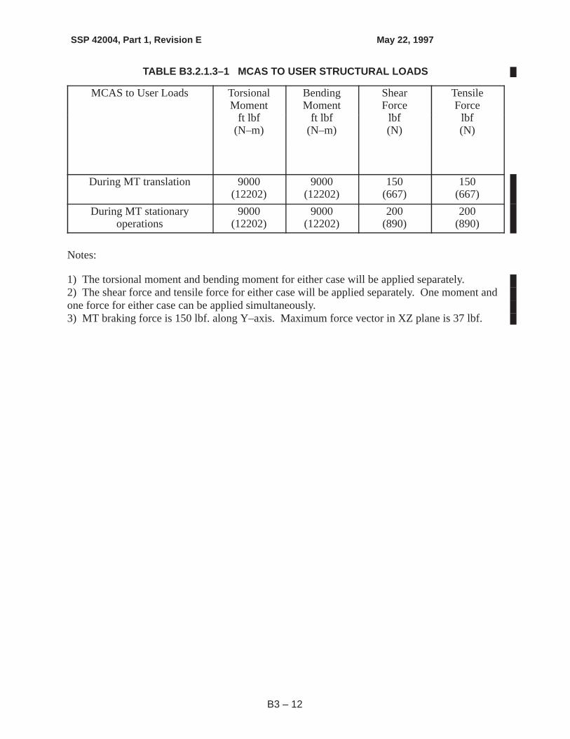

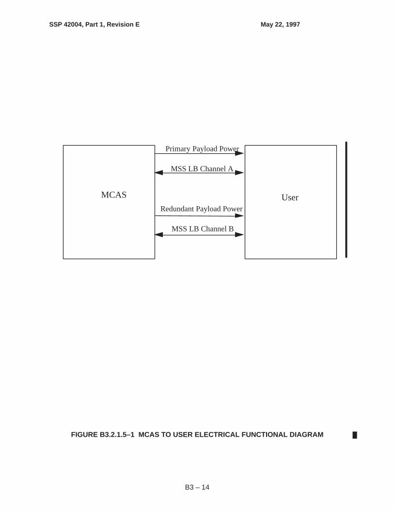


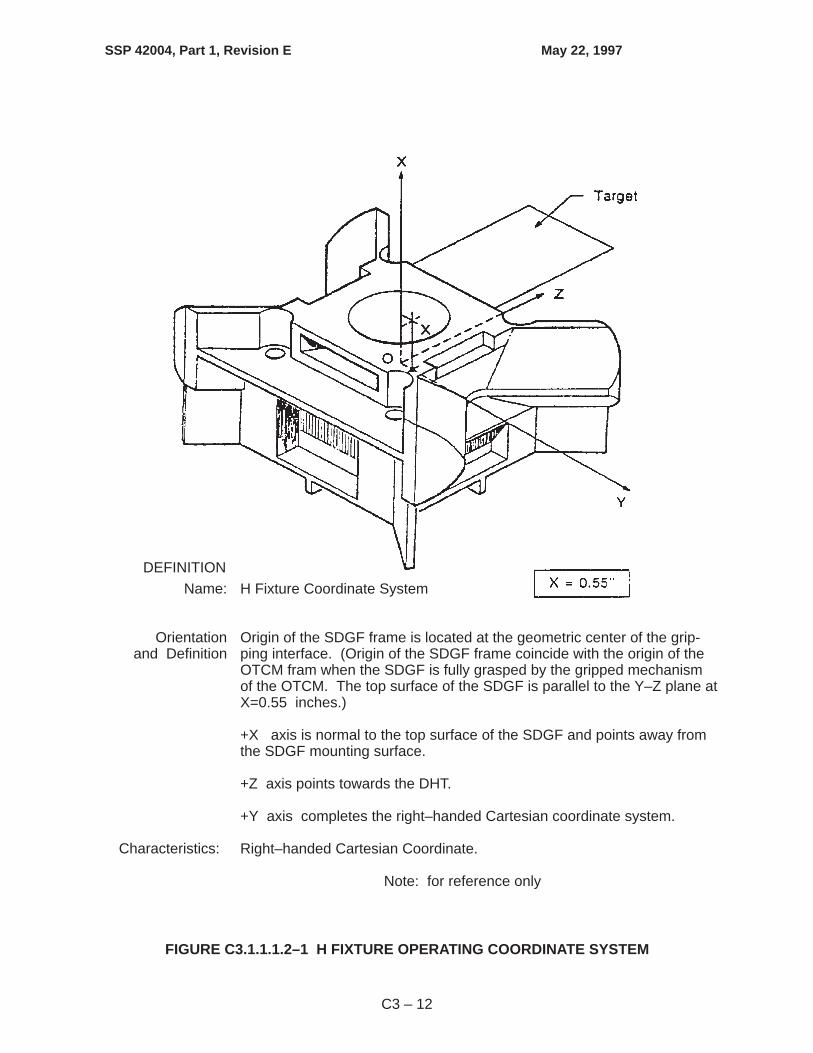


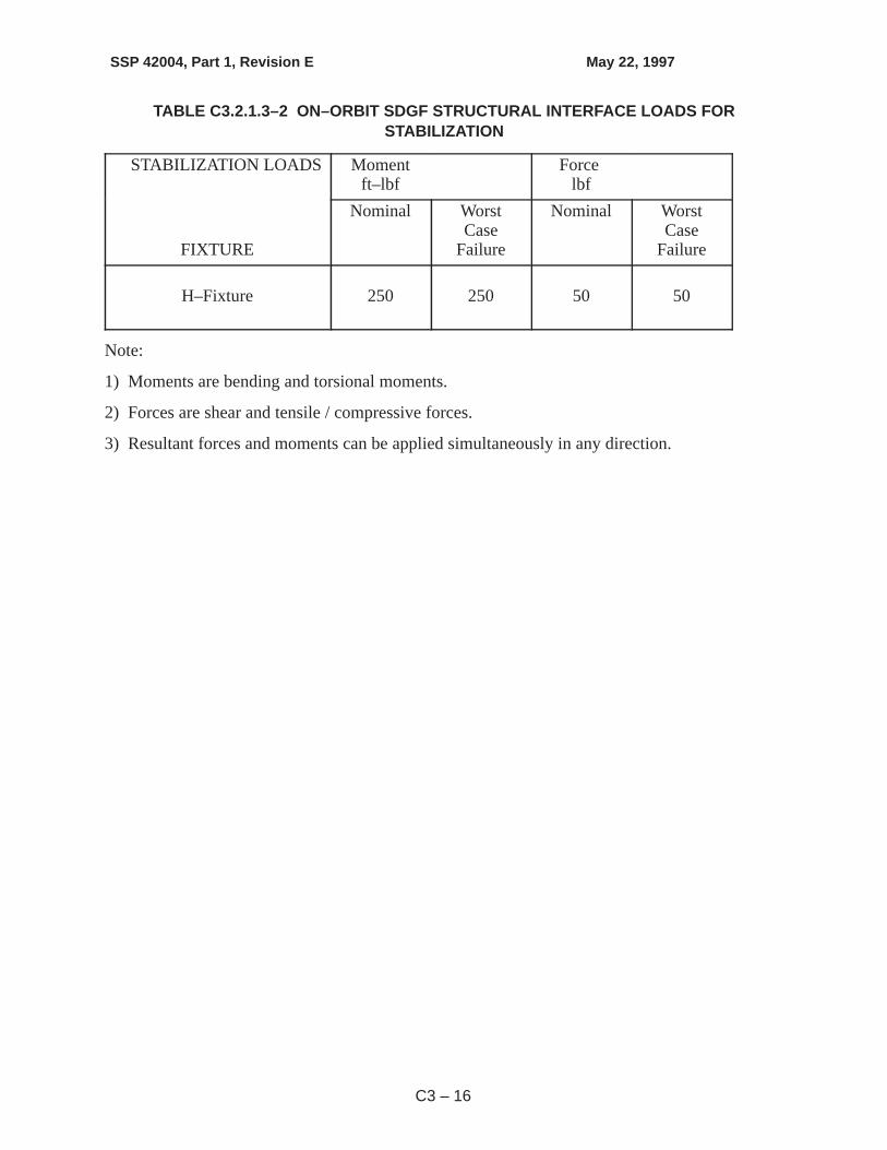


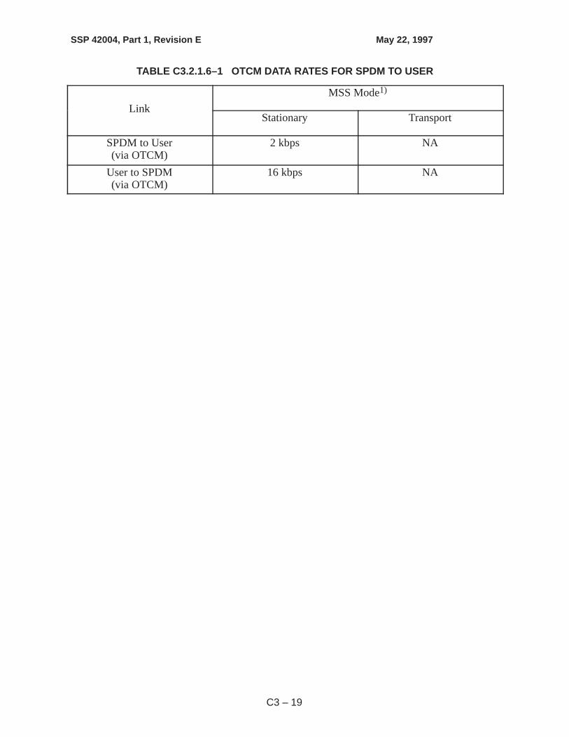


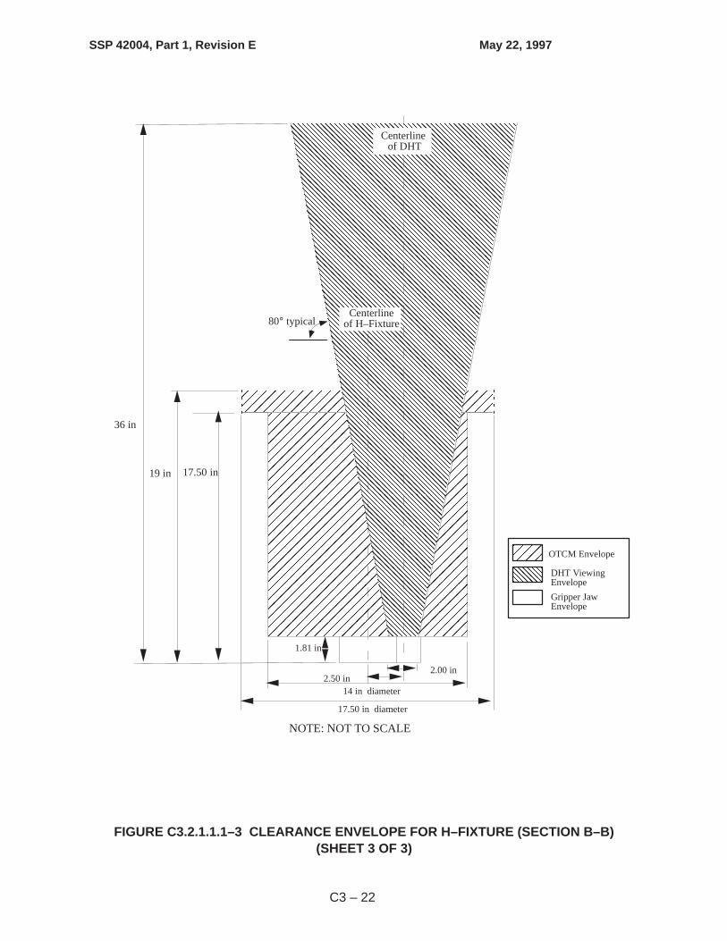


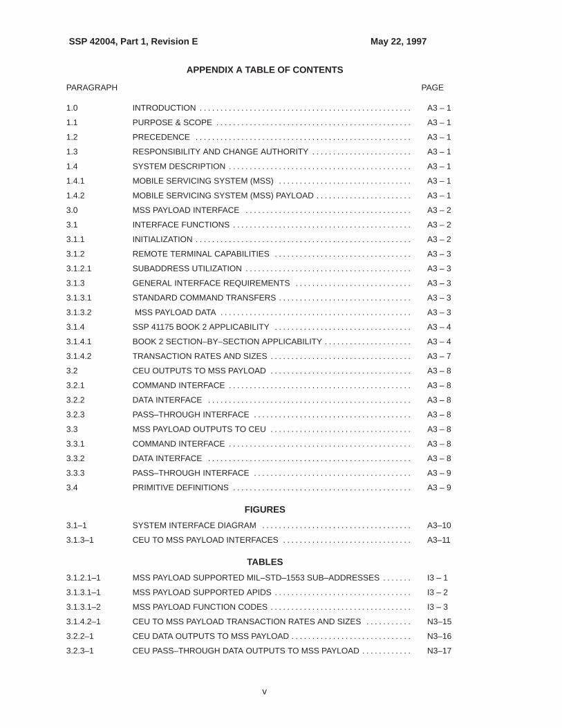


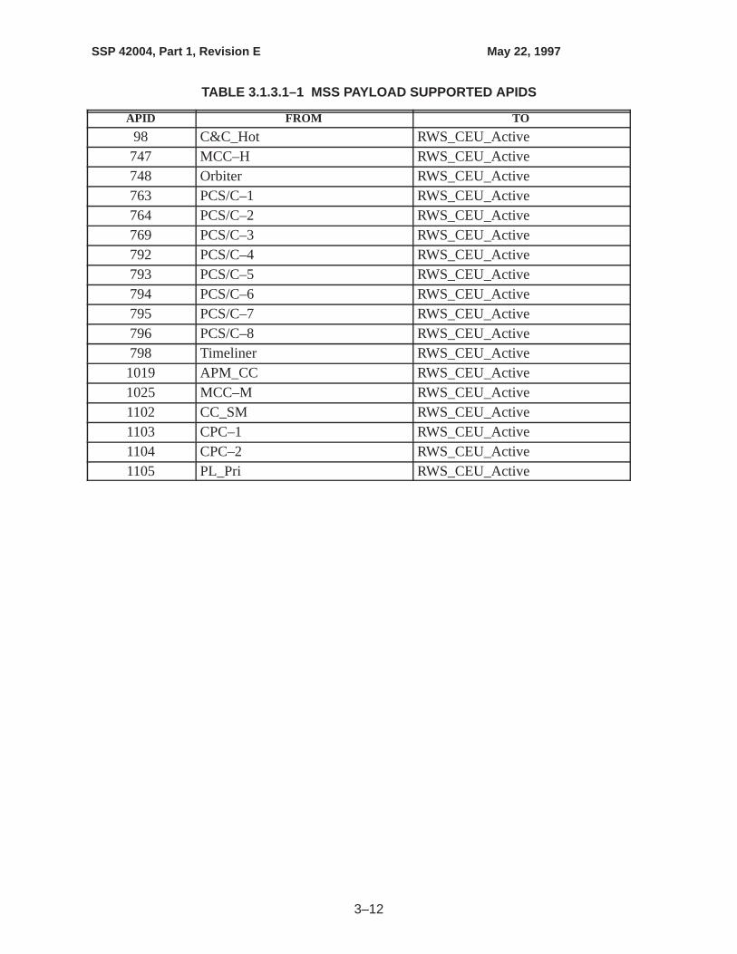


![i cro eparate Screen Y 100 Y) 30 O. 1kWi cro eparate Screen Y 100 Y) 30 O. 1kW 3ØX200VXO.1 kW MSS- 300 MSS- 600 MSS- 900 MSS -1200 MSS- 1500 MSS- 1800 [kg] 200 260 325 455 520 585](https://static.documents.pub/doc/80x56/608f28a1057c035c36673166/i-cro-eparate-screen-y-100-y-30-o-1kw-i-cro-eparate-screen-y-100-y-30-o-1kw.jpg)