30


MOBILE TERMINAL RECEIVER DESIGN

MOBILE TERMINAL RECEIVER DESIGNLTE AND LTE‐ADVANCED
Sajal Kumar DasERICSSON, Bangalore, India
This edition first published 2017© 2017 John Wiley & Sons Singapore Pte. Ltd.
Registered OfficeJohn Wiley & Sons Singapore Pte. Ltd., 1 Fusionopolis Walk, #07‐01 Solaris South Tower, Singapore 138628.
For details of our global editorial offices, for customer services and for information about how to apply for permission to reuse the copyright material in this book please see our website at www.wiley.com.
All Rights Reserved. No part of this publication may be reproduced, stored in a retrieval system or transmitted, in any form or by any means, electronic, mechanical, photocopying, recording, scanning, or otherwise, except as expressly permitted by law, without either the prior written permission of the Publisher, or authorization through payment of the appropriate photocopy fee to the Copyright Clearance Center. Requests for permission should be addressed to the Publisher, John Wiley & Sons Singapore Pte. Ltd., 1 Fusionopolis Walk, #07‐01 Solaris South Tower, Singapore 138628, tel: 65‐66438000, fax: 65‐66438008, email: [email protected].
Wiley also publishes its books in a variety of electronic formats. Some content that appears in print may not be available in electronic books.
Designations used by companies to distinguish their products are often claimed as trademarks. All brand names and product names used in this book are trade names, service marks, trademarks or registered trademarks of their respective owners. The Publisher is not associated with any product or vendor mentioned in this book. This publication is designed to provide accurate and authoritative information in regard to the subject matter covered. It is sold on the understanding that the Publisher is not engaged in rendering professional services. If professional advice or other expert assistance is required, the services of a competent professional should be sought.
Limit of Liability/Disclaimer of Warranty: While the publisher and author have used their best efforts in preparing this book, they make no representations or warranties with respect to the accuracy or completeness of the contents of this book and specifically disclaim any implied warranties of merchantability or fitness for a particular purpose. It is sold on the understanding that the publisher is not engaged in rendering professional services and neither the publisher nor the author shall be liable for damages arising herefrom. If professional advice or other expert assistance is required, the services of a competent professional should be sought.
Library of Congress Cataloging‐in‐Publication Data
Names: Das, Sajal Kumar, author.Title: Mobile terminal receiver design : LTE and LTE-advanced / Sajal Kumar Das.Description: Singapore ; Hoboken, NJ : John Wiley & Sons, 2016. | Includes bibliographical
references and index.Identifiers: LCCN 2016026712 (print) | LCCN 2016035373 (ebook) | ISBN 9781119107309 (cloth) |
ISBN 9781119107439 (pdf) | ISBN 9781119107446 (epub)Subjects: LCSH: Cell phones–Design and construction. | Mobile communication systems–
Technological innovations. | Long-Term Evolution (Telecommunications)Classification: LCC TK6564.4.C45 D37 2016 (print) | LCC TK6564.4.C45 (ebook) | DDC 621.3845/6–dc23LC record available at https://lccn.loc.gov/2016026712
Set in 10/13pt Times by SPi Global, Pondicherry, India
10 9 8 7 6 5 4 3 2 1

Preface xiAbbreviations xiii
1 Introduction to Mobile Terminals 11.1 Introduction to Mobile Terminals 1
1.1.1 Building Blocks of a Smartphone 21.2 History of the Mobile Phone 41.3 Growth of the Mobile Phone Market 51.4 Past, Present, and Future of Mobile Communication Devices 8Further Reading 8
2 Cellular Systems Modems 92.1 Introduction to Modems 92.2 Telecommunication Networks 102.3 Cellular Concepts 142.4 Evolution of Mobile Cellular Networks 162.5 First‐Generation (1G) Cellular Systems 16
2.5.1 First‐Generation Mobile Phone Modem Anatomy 182.6 Cellular System Standardization 182.7 Second‐Generation (2G) Cellular Systems 19
2.7.1 GSM System 202.8 GSM Mobile Phone Modem Anatomy 27
2.8.1 Receiver Unit 272.8.2 Transmitter Unit 33
2.9 Channel Estimation and Equalization in GSM Mobile Terminals 332.9.1 Channel Condition Detection Techniques 342.9.2 Protocol Stack of GSM Mobile 38
Contents
vi Contents
2.10 Third‐Generation (3G) Cellular Systems 402.10.1 Overview of UMTS System Architecture 402.10.2 UMTS Air Interface 412.10.3 Physical Channel Transmission 462.10.4 UMTS UE Protocol Architecture 522.10.5 UMTS Addressing Mechanism 572.10.6 Radio Links, Radio Bearers, and Signal Radio Bearers 58
2.11 UMTS UE System Operations 582.11.1 Carrier RSSI Scan 582.11.2 Cell Search 582.11.3 System Information Reception 602.11.4 Paging Reception and DRX 612.11.5 RRC Connection Establishment 62
2.12 WCDMA UE Transmitter Anatomy 652.13 WCDMA UE Receiver Anatomy 67
2.13.1 Baseband Architecture 672.14 Evolution of the UMTS System 71
2.14.1 HSDPA 722.14.2 HSUPA 762.14.3 HSPA+ 812.14.4 Receiver Architecture (RAKE and G-RAKE)
Evolution for WCDMA 83References 85Further Reading 85
3 LTE Systems 873.1 LTE Cellular Systems 873.2 3GPP Long‐Term Evolution (LTE) Overview 88
3.2.1 LTE Design Goals 883.3 3GPP LTE Specifications 893.4 LTE Network Architecture 893.5 Interfaces 913.6 System Protocol Architecture 91
3.6.1 User Plane Data Flow Diagram 933.6.2 Protocol States 933.6.3 Bearer Service Architecture 95
3.7 LTE‐Uu Downlink and Uplink Transmission Schemes and Air Interface 953.7.1 Downlink Transmission Scheme 953.7.2 LTE Downlink Frame Structure 1003.7.3 Uplink Transmission Scheme and Frame Structure 103
3.8 Channel Structure 1043.8.1 Downlink Channel Structure and
Transmission Mechanism 105

Contents vii
3.8.2 Downlink Physical Channel Processing 1243.8.3 Uplink Channel Structure and Transmission Mechanism 1283.8.4 Uplink Physical Channel Processing 131
3.9 Multiple Input Multiple Output (MIMO) 1333.9.1 MIMO in the LTE System 1353.9.2 Transmission Mode (TM) 136
3.10 Uplink Hybrid Automatic Repeat Request (ARQ) 1373.11 UE Categories 1373.12 LTE UE Testing 137References 139Further Reading 139
4 LTE UE Operations Procedures and Anatomy 1404.1 UE Procedures 1404.2 Network and Cell Selection in Terminals 142
4.2.1 PLMN Selection 1424.2.2 Closed Subscriber Group Selection 1444.2.3 Cell Selection Criteria 144
4.3 Cell Search and Acquisition 1454.3.1 Cell Search and Synchronization Procedure 145
4.4 Cell‐Specific Reference (CRS) Signal Detection 1484.5 PBCH (MIB) Reception 1504.6 PCFICH Reception 1524.7 PHICH Reception 1524.8 PDCCH Reception 152
4.8.1 Implementation of Control Channel Decoder 1534.9 PDSCH Reception 1554.10 SIB Reception 1554.11 Paging Reception 155
4.11.1 Calculation of Paging Frame Number 1564.11.2 Paging Procedure 156
4.12 UE Measurement Parameters 1584.13 Random Access Procedure (RACH Transmission) 159
4.13.1 Preamble Transmission by UE 1604.14 Data Transmission 1624.15 Handover 164
4.15.1 Idle State Mobility Management 1664.15.2 Interoperability with Legacy Systems (I‐RAT) 166
4.16 Anatomy of an LTE UE 1674.17 Channel Estimation 1684.18 Equalization 1704.19 Detection 1724.20 Decoder 173Reference 173Further Reading 173

viii Contents
5 Smartphone Hardware and System Design 1745.1 Introduction to Smartphone Hardware 1745.2 Smartphone Processors 174
5.2.1 Processor Operations 1785.2.2 Processor Types 1795.2.3 Advanced Risk Machine (ARM) 1815.2.4 DSP‐Based Implementation 1895.2.5 SOC‐Based Architecture 1895.2.6 Commonly Used Processors in Smart Phones 190
5.3 LTE Smartphone Hardware Implementation 1905.4 Memory 191
5.4.1 Read‐Only Memory (ROM) 1925.4.2 Flash Memory 1935.4.3 Random‐Access Memory (RAM) 194
5.5 Application Processing Unit 1965.5.1 Application Processor Peripherals 196
5.6 Multimedia Modules 1975.7 Microphone 197
5.7.1 Principle of Operation 1975.8 Loudspeaker 2005.9 Camera 2015.10 Display 2025.11 Keypad and Touchscreen 2035.12 Analog‐to‐Digital Conversion (ADC) Module 2055.13 Automatic Gain Control (AGC) Module 2075.14 Frequency Generation Unit 2095.15 Automatic Frequency Correction (AFC) Module 212
5.15.1 The Analog VC‐TCXO 2135.15.2 Digitally Controlled Crystal Oscillators – DCXO 213
5.16 Alert Signal Generation 2155.17 Subscriber Identity Module (SIM) 2165.18 Connectivity Modules 217
5.18.1 Bluetooth 2175.18.2 USB 2195.18.3 WiFi 222
5.19 RF Baseband (BB) Interface 2265.20 System Design 226
5.20.1 System Design Goal and Metrics 2275.20.2 System Architecture 228
Reference 229Further Reading 229
6 UE RF Components and System Design 2306.1 Introduction to RF Systems 2306.2 RF Front‐End Module (FEM) 230
6.2.1 Antenna 230

Contents ix
6.2.2 Baluns 2426.2.3 Mixers 247
6.3 RF Downconversion 2516.3.1 Different Types of RF Downconversion Techniques 2516.3.2 Homodyne Receivers 2566.3.3 Low IF Receiver 2646.3.4 Wideband IF Receivers 267
6.4 Receiver Performance Evaluation Parameters 2696.4.1 Receiver Architecture Comparison 2726.4.2 Other Feasible Architectures 2726.4.3 Path to Future Receivers 272
6.5 RF Transmitter 2726.5.1 Power‐Limited and Bandwidth‐Limited Digital
Communication System Design 2756.5.2 Investigation of the Tradeoffs between Modulation
and Amplifier Nonlinearity 2786.6 Transmitter Architecture Design 279
6.6.1 Nonlinear Transmitters 2806.6.2 Linear Transmitters 2806.6.3 Common Architecture for Nonlinear and
Linear Transmitters 2816.6.4 Polar Transmitter 2836.6.5 Power Amplifier (PA) 285
6.7 Transmitter Performance Measures 2886.7.1 Design Challenges 289
6.8 LTE Frequency Bands 289Further Reading 291
7 Software Architecture Design 2927.1 Introduction 2927.2 Booting Process 292
7.2.1 Initialization (Boot) Code 2947.3 Operating System 298
7.3.1 Commonly Used Mobile Operating Systems 2997.3.2 Real‐Time Operating System 3027.3.3 OS Operation 3027.3.4 Selection of an Operating System 303
7.4 Device Driver Software 3037.5 Speech and Multimedia Application Software 304
7.5.1 Speech Codec 3047.5.2 Voice Support in LTE 3097.5.3 Audio Codec 3107.5.4 Images 3117.5.5 Video 313

x Contents
7.6 UE Protocol Stack Software 314Further Reading 316
8 Battery and Power Management Unit Design 3178.1 Introduction to the Power Management Unit 3178.2 Battery Charging Circuit 318
8.2.1 Battery Charging from a USB Port 3198.2.2 Wireless Charging 320
8.3 Battery 3208.3.1 Battery Working Principles 3208.3.2 Power versus Energy 3228.3.3 Talk Time and Standby Time 3228.3.4 Types of Rechargeable Batteries and Performance Parameters 322
8.4 Mobile Terminal Energy Consumption 3248.4.1 System‐Level Analysis of Power Consumption 325
8.5 Low‐Power Smartphone Design 3268.6 Low‐Power Design Techniques 327
8.6.1 System‐Level Power Optimization 3278.6.2 Algorithmic Level 3298.6.3 Technology 3308.6.4 Circuit/Logic 3318.6.5 Architecture 3328.6.6 Power Consumption in Microprocessors 3328.6.7 Power Consumption in Memory 332
Further Reading 335
9 4G and Beyond 3379.1 Introduction to LTE‐Advanced 3379.2 LTE‐Advanced Features 337
9.2.1 Carrier Aggregation 3379.2.2 Enhanced Uplink Multiple Access 3419.2.3 Enhanced Multiple Antenna Transmission 3429.2.4 Relaying 3429.2.5 Device to Device 3429.2.6 Coordinated Multipoint (CoMP) 3449.2.7 Heterogeneous Networks and Enhanced ICIC 3449.2.8 LTE Self‐Optimizing Networks (SON) 346
9.3 LTE‐A UE Modem Processing 3469.4 LTE‐A UE Implementation 3479.5 Future Generations (5G) 3489.6 Internet of Things (IoT) 350Further Reading 351
Index 352

Mobile systems have evolved over several generations, from 1G to 4G and beyond, due to an ongoing demand for higher data rates, for better quality, for more complex applications, and for seamless intersystems handover and lower latency. As a result, the mobile phone has changed from a simple telephone to a complex smartphone. Today, a smartphone encapsulates computing capabilities with cellular network access functionality in a single integrated system, with high‐quality graphics, a portable size, support for complex user applications, and multimode connectivity features. The demand for supporting various complex applications, new applications, smaller form factors, lower power consumption, and multi‐RAT support, has meant that the challenges in mobile phone design have been manifold. In particular, new challenges have arisen in the design of innovative mobile handset solutions, which can offer smaller sizes, low power consumption, low cost, and tremendous flexibility, while supporting more advanced features and providing an improved data rate and higher performance.
This book has been written to address these challenges. Its aim has been to equip mobile phone system designers and students with an all‐in‐one guide, starting from basic concepts and progressing to advanced system design, and introducing readers to various innovative solutions. It walks readers through 2G, 3G, and 4G mobile‐phone system architectures and their basic building blocks, the different air‐interface standards, operating principles, hardware anatomy, software and protocols, internal modules, components, and circuits for legacy and next‐generation smartphones, including various research areas in 4G and 5G systems.
Mobile Terminal Receiver Design explains basic working principles, system architecture, and specification details of legacy and next‐generation mobile systems. It covers in detail RF transmitter and receiver blocks, digital baseband processing blocks, receiver and trans-mitter signal processing, protocol stacks, AGC, AFC, ATC, the power supply, clocking, connectivity modules, and application modules with different design solutions for exploring
Preface
xii Preface
various tradeoffs. It also explains the internal blocks, hardware and software components, and anatomy of legacy and LTE/LTE‐Advanced smartphones, from principle to practice to product. Multi‐RAT design requirements are also discussed, together with key design attributes such as low power consumption, slim form factors, seamless I‐RAT handover, sensitivity, and selectivity.
This book is based on my experiences as a design engineer in the field of wireless and mobile communications and modelled from an academic course developed for electronics communication engineering students, and from a useful design handbook for practicing engi-neers and technicians. It is intended to help software, hardware and RF design engineers, researchers, product managers, as well as industry veterans in the areas of mobile phone system and chipset design to understand the evolution of radio access technologies and emergent trends, and also to help them make innovative and competitive next‐generation mobile devices.
I express my sincere thanks to my colleagues, friends and family members for their valuable suggestions. Any constructive criticisms and suggestions for improving the book will be gratefully received and should be sent to [email protected].
Dr Sajal Kumar Das
3GPP – Third‐Generation Partnership ProjectACK – acknowledgment (in ARQ protocols)ADC – analog to digital converterAM – amplitude modulationAMPS – advanced mobile phone serviceAMR – adaptive multirate (speech codec)APN – access point nameARQ – automatic repeat requestAWGN – additive white Gaussian noiseBCCH – broadcast control channelBCH – broadcast channelBER – bit error rateCDMA – code division multiple accessCFO – carrier frequency offsetCMOS – complementary metal oxide semiconductorCN – core networkCPC – continuous packet connectivityCQI – channel quality indicatorCRC – cyclic redundancy checkCS – circuit switchedDCCH – dedicated control channelDECT – digital European cordless telephoneDFE – digital front endDigRF – digital RF interface standardDL – downlinkDL‐SCH – downlink shared channelDPCCH – dedicated physical control channel
Abbreviations

xiv Abbreviations
DRX – discontinuous receptionDS‐CDMA – direct sequence code division multiple accessDSP – digital signal processorDTCH – dedicated traffic channelDTX – discontinuous transmissionDwPTS – downlink pilot time slotEDGE – enhanced data rates for GSM evolutioneNB – E‐UTRAN Node BEPC – evolved packet coreEPS – evolved packet systemETACS – extended total access communication systemEUTRA – evolved universal terrestrial radio accessE‐UTRAN – evolved UTRANFCC – Federal Communication CommissionFDD – frequency division duplexFDMA – frequency division multiple accessFEC – forward error correctionFER – frame error rateFFT – fast Fourier transformFTP – file transfer protocolGaAS – gallium arsenideGERAN – GSM EDGE radio access networkGP – guard periodGPRS – general packet radio servicesGSM – Global System for Mobile CommunicationsGSM‐EFR – GSM enhanced full rateHARQ – hybrid ARQHSDPA – high‐speed downlink packet accessHSPA – high‐speed packet accessHSUPA – high‐speed uplink packet accessICI – intercarrier interferenceIFFT – inverse FFTIMT – International Mobile TelecommunicationIP – Internet protocolLTE – Long‐Term EvolutionMAC – medium access controlMBMS – multimedia broadcast and multicast serviceMCH – multicast channelMCS – modulation and coding schemeMIMO – multiple input multiple outputMTCH – MBMS traffic channelNACK – negative acknowledgment (in ARQ protocols)

Abbreviations xv
NAS – nonaccess stratumOFDM – orthogonal frequency division multiplexingOFDMA – orthogonal frequency division multiple accessPAPR – peak‐to‐average power ratioPBCH – physical broadcast channelPCCH – paging control channelPCFICH – physical control format indicator channelPCS – personal communication standardPDC – personal digital cellularPDCP – packet data convergence protocolPDCCH – physical downlink control channelPDC‐EFR – PDC‐enhanced full ratePDCP – packet‐data convergence protocolPDSCH – physical downlink share channelPDN – packet data networkP‐GW – packet data network gatewayPHICH – physical hybrid ARQ indicator channelPMCH – physical multicast channelPMI – precoding matrix indicatorPOCSAG – Post Office Code Standard Advisory GroupPRB – physical resource blockPSHO – packet switched handoverP‐SS – primary synchronization signalPUSCH – physical uplink shared channelQAM – quadrature amplitude modulationQoS – quality of serviceQPSK – quadrature phase‐shift keyingRB – radio bearerRB – resource blockRF – radio frequencyRF‐BB – radio frequency and baseband moduleRL – radio linkRLC – radio link controlROHC – robust header compressionRRC – radio resource controlRS – reference signalRTT – radio transmission technologyRV – redundancy versionSAE – system architecture evolutionSC‐FDMA – single carrier frequency division multiple accessSCTP/IP – stream control transmission protocol / IPSMS – short message service

xvi Abbreviations
SR – scheduling requestSRB – signal radio bearerS‐SS – secondary synchronization signalTDD – time division duplexTDMA – time division multiple accessTDMA‐EFR – TDMA enhanced full rateTE – transverse electricTEM – transverse electromagneticTM – transverse magneticTR – technical releaseTTI – transmission time intervalUE – user equipmentUL – uplinkUL‐SCH – uplink shared channelUMTS – universal mobile telecommunications systemUTRA – universal terrestrial radio accessUTRAN – universal terrestrial radio access networkVoIP – voice over IPWDT – watchdog timer

Mobile Terminal Receiver Design: LTE and LTE-Advanced, First Edition. Sajal Kumar Das. © 2017 John Wiley & Sons Singapore Pte. Ltd. Published 2017 by John Wiley & Sons Singapore Pte. Ltd.
Introduction to Mobile Terminals
1.1 Introduction to Mobile Terminals
A mobile communication device is a small, portable electronic device, with wireless communication capabilities, which is easy to carry around. There are several types of mobile communication devices, like cell phones or mobile phones, WLAN devices, and GPS navigation devices, but it is the mobile phone that has adopted the term “mobile device,” and gradually its purpose has shifted from a verbal communication tool to a multimedia tool.
A mobile phone, which is also known as mobile terminal (MT), cellular phone, cell phone, hand phone, or simply a phone, is a device that can send and receive telephone calls over a radio link while being connected to a cellular base station operated by a cellular network operator. It provides user mobility around a wide geographic area. A feature phone is a low‐end mobile phone with limited capabilities and it provides mainly voice calling, text messaging, multimedia, and Internet functionality. In addition to telephone calls, modern multifunctional mobile phones with more computing capabilities, which support a wide variety of other applications and services like SMS, MMS, e‐mails, Internet, Web browsing, news, gaming, playing music, movies, calendar management, contact, video, photography, short‐range connectivity, location‐specific information, WLAN connectivity, and GPS connectivity, are considered as smartphones. Smartphones offer all these services in single device, so they are becoming increasingly important as work tools for users who rely on these services. Today, they have become universal replacements for personal digital assistant (PDA) devices. Typically, a smartphone incorporates handheld computer functionalities along with the communication capabilities of a cell phone by providing support
1

2 Mobile Terminal Receiver Design
of multimodal, multi‐RAT connectivity and user customized applications. Personal digital assistants / enterprise digital assistants, tablet computers, ultramobile PCs, and a lot of wearable devices also provide mobile communication capabilities by integrating communication modems in them. Various types of these devices are shown in Figure 1.1.
1.1.1 Building Blocks of a Smartphone
A system‐level block diagram of a smartphone is shown in Figure 1.2. Smartphones are equipped with various functional blocks as given below:
• Mobile terminal modem unit. This unit (cellular systems modem) interfaces with the cellular base stations, and sends / receives user information (voice, data) generated by the application unit. So it interacts with a base station using different cellular air interface standards like GSM, WCDMA, LTE etc. to send / receive information to distantly located called party or server. It also interacts locally with its application units, like speech, video, and data transfer applications for getting / providing the user application data. This is discussed in Chapters 2, 3 and 4. This consists of two main submodules: Radio Frequency (RF) unit and Baseband (BB) unit.
◦ RF unit. The RF analog front‐end unit’s transmitter circuit helps to upconvert the low‐frequency baseband signal to a high‐frequency amplified RF signal for transmission, and the receiver circuit helps to downconvert the analog amplified received high‐frequency signal to a low‐frequency baseband signal. The RF unit is discussed in detail in Chapter 6.
◦ Baseband unit. The baseband unit helps for digital bit detection, system protocol processing for proper and reliable communication with the network. These are discussed in detail in Chapter 4 and 5.
◦ SIM. A subscriber identification module (SIM) is an integrated circuit that securely stores the international mobile subscriber identity (IMSI) and the related key used to identify and authenticate subscribers on mobile telephony devices. A SIM circuit is embedded into a removable plastic card, called “SIM card.” This is discussed in detail in Chapter 5.
(a) (b) (c) (d)
Figure 1.1 (a) PDA, (b) smartphone (c) tablet (d) wearable device

Introduction to Mobile Terminals 3
• Application unit. This unit is in charge of running various applications. It interacts with the modem and connectivity modules to send / receive information from remote devices, and uses that data to drive various applications. It provides the functions that users want to execute on the smart phone and these may include speech, audio playback, fax transmission / reception, Internet, e‐mail, Web browsing, image reproduction, streaming video, games, and so forth. This unit also handles the interface functions such as keyboard, display, and speech recognition, and it interfaces and manages other connectivity modules such as GPS and WLAN. Depending on the smartphone device complexity, there could one or several application processors in a mobile phone. The architecture design and selection details are provided in Chapter 5 and 7. The application processor consists of components like the processor core and device interfaces, which communicate with other peripheral devices attached to the application processor like the LCD screen, camera, keypad, universal serial bus (USB), and multimedia card (MMC) via interfaces. These are discussed in detail in Chapter 5.
◦ Peripheral devices. There are several peripheral devices placed in the smart phone for different purposes. Like, for data transfer with other devices or PC, an USB device is placed in the phone. Similarly, UART, I2S etc. are used for intermodule or interdevice communication. The other devices are like, SD / MMC, LCD display, keyboard, microphone, and speaker are also used in a mobile phone. These are discussed in detail in Chapter 5.
◦ Multimedia modules. It performs multimedia related functions like, speech encoding /decoding, audio encoding / decoding, video encoding / decoding by employing various multimedia standards (MP3, JPEG, MPEG, and so forth). As multimedia‐related functions are time consuming, so these are generally implemented in dedicated hardware block. Also, smartphone contain graphics processing unit (GPU) for rapid processing of multimedia functions. These are discussed in detail in Chapters 5 and 7.
Application processor
ApplicationsMemory
Flash Vibrator
MICSpeaker
CameraImage Block
Various sensors
Cell basestations
GPS
RF
RF Baseband
Baseband
Cellular systems modem (GSM, WCDMA, LTE..)
Connectivity modules(WLAN, BT, GPS,....)
Battery and powermanagement unit
Clock distribution unit
Modem-ApplicationInterface (e.g. AT-CMD) Display
Touchscreen key
MotorUSB
SIM
SDRAM
Protocol Stack (AS and NAS)Phy layerRx / Tx signal processing
Audio block(Encoder / Decoder)
Figure 1.2 System‐level block diagram of a typical smartphone

4 Mobile Terminal Receiver Design
◦ Various sensors and actuators. A sensor is a device that measures a physical quantity and converts it into a signal (electrical or optical) by an instrument. They sense the changes in the environment and send them to the application processor. The commonly used sensors in handsets include accelerometers, gyroscopes, proximity sensors, ambient light sensors, barometers, and so forth. On the other hand, an actuator is a type of motor that is responsible for moving or controlling a mechanism or a system. These are discussed in detail in Chapter 5.
◦ Vibrator. A vibra alert device is used to give a silent alert signal to the phone user. Generally the vibration is made using an improperly balanced motor and controlled with a pulse width modulation (PWM) signal via the battery terminal. These are discussed in detail in Chapter 5.
◦ Connectivity modules. Apart from cellular system modem, the smart phone also houses several other wireless connectivity modules like, Geo Positioning System (GPS), Bluetooth (BT), FM radio, ZigBee, Wireless LAN (WLAN), and so forth. These individual submodules have RF and digital baseband processing unit and interact with the other devices, peripherals like, headset or server through radio interface. These are discussed in detail in Chapter 5.
• Power management module. This unit is responsible for distributing the regulated battery power among various modules, conversion of the battery voltage (generally 3.6 V) according to the different voltage level needed by different modules, which means up or down conversion to various voltages (such as 4.8 V, 2.8 V, 1.8 V and 1.6 V) using, for example, a DC‐DC converter, a battery power consumption control device, sleep‐related functionalities management, battery‐charging control. The battery‐charging component is responsible for charging the battery of the smartphone. These are discussed in detail in Chapter 8.
• Clock distribution module. This distributes a clock signal to the mobile phone. The clock signal is required in every digital blocks in the system and also it is required in RF unit for scheduling transmission and reception at a specific time. These are discussed in detail in Chapter 5.
• Memory. Various types of memory are used in the mobile phone for storing code and data. Generally, Flash memory, EPROM, and DRAM memory are used in a mobile phone. These are discussed in detail in Chapter 5.
Apart from all these hardware blocks, firmware and software components reside in the memory and are executed by processors to configure, control, and process different hardware modules, applications, and protocols. These are discussed in Chapter 7.
1.2 History of the Mobile Phone
Prior to 1973, mobile telephony was limited to phones installed in cars, trains and other vehicles, mainly due to the larger size and weight of the equipment. On April 3, 1973, Martin Cooper, a senior engineer at Motorola, made the first mobile telephone call from
Introduction to Mobile Terminals 5
handheld subscriber equipment, which was around 23 cm long, 13 cm deep and 4.45 cm wide and weighed 1.1 kg and offered a talk time of just 30 min with 10 h of recharge time. Since then, mobile phones have evolved dramatically, with enriched features like audio, and video players, video cameras, handheld gaming devices and support for Internet access, augmented reality, commercial services and a whole host of other applications. They also reduced in size, weight, and cost.
In 1992 Motorola introduced the first digital palm‐size mobile telephone named Motorola 3200. In 1992, Nokia developed Nokia 1011, which was first mass‐produced GSM phone. In 1992 IBM introduced Simon, a personal communicator with PDA and phone combination, which had a monochrome touchscreen and a stylus. In 1996, Nokia introduced the communicator 9000 series as a smart phone with outward facing dial pad, navigation keys, and monochromatic display. Nokia 7120 supported WAP browser. One year later, Ericsson released the GS 88 smart phone with a touchscreen inside and a stylus. Samsung Uproar cell phone was introduced with MP3 music capabilities. Nokia 8310 was having several premium features such as FM radio, infrared, and a fully functional calendar. Ericsson T39 was a tiny Bluetooth‐capable handset. In 1999, NTT DoCoMo pioneered the first mobile Internet service in Japan on existing 2G technologies, which was soon replaced by the first 3G handsets in October 2001. In 2002, the first phones with built‐in cameras became publicly available in the Nokia 7650 and the Sanyo SPC‐5300. In 2004, Motorola introduced Razor V3, which is a very lightweight sleek phone. In January 2007, Apple launched its first iPhone, combining three products into one handheld device: a mobile phone, an iPod, and a wireless communication device, which had an autorotate and a multitouch sensor. This device helped Apple to capture a significant market share. In 2008, Nokia released a GPS‐enabled smartphone with sleek, compact design.
The mobile phone continues to evolve. In 2008 LTE standardization was released and today the most recent phone comes with fourth‐generation (4G) technology. This allows users to download music, watch videos, make video calls and join video conferences at much faster speeds. Today, this magical portable technology box has become an essential part of interpersonal communication and its significance is further increasing over time.
1.3 Growth of the Mobile Phone Market
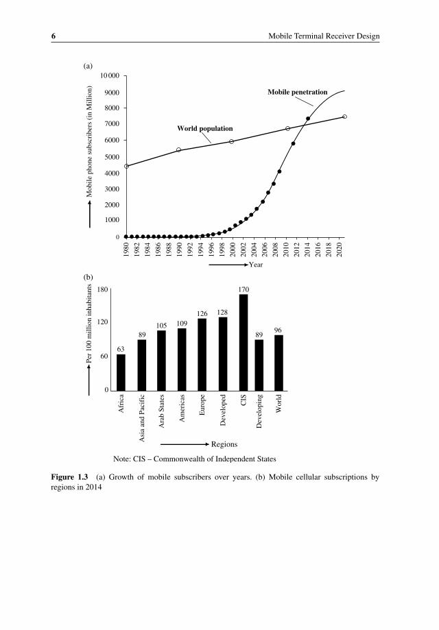
The first mobile subscriptions took place in the early 1980s. During that period the total number of mobile phones in the market were around 0.023 million. Since then aided by affordability of cheap mobile phones and support of newer features fueled the mobile phone growth year after year. Figure 1.3(a) shows the growth of mobile subscribers since 1980 (according to ITU published figures). In 2014, the number of worldwide mobile users reached more than 5.6 billion (whereas world human population was 7.1 billion).
Low‐end mobile phones are often referred to as feature phones. They are limited in their capabilities and primarily designed for basic telephony services. Handsets with more advanced computing ability, hosting a lot of other features apart from voice communication,
6 Mobile Terminal Receiver Design
Figure 1.3 (a) Growth of mobile subscribers over years. (b) Mobile cellular subscriptions by regions in 2014
(a)
World population
1000
0
1980
1982
1984
1986
1988
1990
1992
1994
1996
1998
2000
2002
2004
2006
2008
2010
2012
2014
2016
2018
2020
2000
3000
4000
5000
6000
7000
8000
9000
10 000
Mobile penetration
Year
Mob
ile p
hone
sub
scri
bers
(in
Mill
ion)
(b)
0
6063
Afr
ica
Asi
a an
d Pa
cifi
c
Ara
b St
ates
Am
eric
as
Eur
ope
Dev
elop
ed
CIS
Dev
elop
ing
Wor
ld
89105 109
126 128
170
8996
120
180
Regions
Note: CIS – Commonwealth of Independent States
Per
100
mill
ion
inha
bita
nts
Introduction to Mobile Terminals 7
are known as smartphones. Recently, smartphone penetration has increased significantly due to greater use of the Internet and complex applications. Global smartphone users surpassed the 1 billion mark in 2012 and in 2014 touched around 1.75 billion. Figure 1.3(b) shows mobile phone penetration by geographic regions.
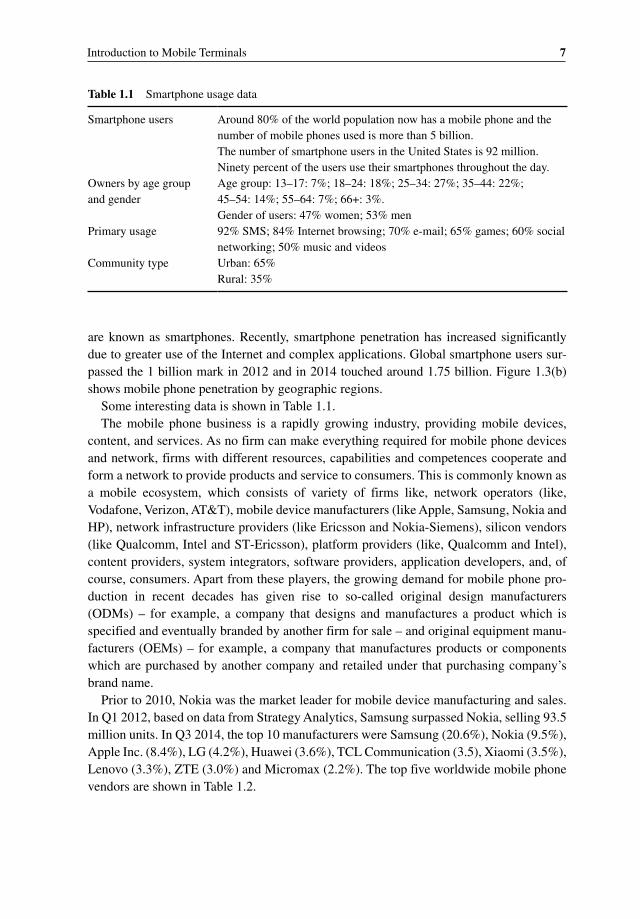
Some interesting data is shown in Table 1.1.The mobile phone business is a rapidly growing industry, providing mobile devices,
content, and services. As no firm can make everything required for mobile phone devices and network, firms with different resources, capabilities and competences cooperate and form a network to provide products and service to consumers. This is commonly known as a mobile ecosystem, which consists of variety of firms like, network operators (like, Vodafone, Verizon, AT&T), mobile device manufacturers (like Apple, Samsung, Nokia and HP), network infrastructure providers (like Ericsson and Nokia‐Siemens), silicon vendors (like Qualcomm, Intel and ST‐Ericsson), platform providers (like, Qualcomm and Intel), content providers, system integrators, software providers, application developers, and, of course, consumers. Apart from these players, the growing demand for mobile phone production in recent decades has given rise to so‐called original design manufacturers (ODMs) – for example, a company that designs and manufactures a product which is specified and eventually branded by another firm for sale – and original equipment manufacturers (OEMs) – for example, a company that manufactures products or components which are purchased by another company and retailed under that purchasing company’s brand name.
Prior to 2010, Nokia was the market leader for mobile device manufacturing and sales. In Q1 2012, based on data from Strategy Analytics, Samsung surpassed Nokia, selling 93.5 million units. In Q3 2014, the top 10 manufacturers were Samsung (20.6%), Nokia (9.5%), Apple Inc. (8.4%), LG (4.2%), Huawei (3.6%), TCL Communication (3.5), Xiaomi (3.5%), Lenovo (3.3%), ZTE (3.0%) and Micromax (2.2%). The top five worldwide mobile phone vendors are shown in Table 1.2.
Table 1.1 Smartphone usage data
Smartphone users Around 80% of the world population now has a mobile phone and the number of mobile phones used is more than 5 billion.The number of smartphone users in the United States is 92 million.Ninety percent of the users use their smartphones throughout the day.
Owners by age group and gender
Age group: 13–17: 7%; 18–24: 18%; 25–34: 27%; 35–44: 22%; 45–54: 14%; 55–64: 7%; 66+: 3%.Gender of users: 47% women; 53% men
Primary usage 92% SMS; 84% Internet browsing; 70% e‐mail; 65% games; 60% social networking; 50% music and videos
Community type Urban: 65%Rural: 35%

8 Mobile Terminal Receiver Design
1.4 Past, Present, and Future of Mobile Communication Devices
In the past, the use of a mobile phone was mainly for voice communication, but today there are thousands of applications that a mobile phone offers, including text messaging (SMS), a multimedia messaging service (MMS), Internet access, Web browsing, sending and receiving e‐mails, listening to music, reading books, video chat, video recording, location service, time watching, alarm, calendar, calculator. Apart from these, nowadays mobile phones are also used in the field of telemedicine, healthcare, and wearables. In future it has huge potential to be used for watching TV, controlling and tracking remove devices, home automation, object recognition, e‐commerce, and so forth.
Further Reading
Arrepim, http://stats.areppim.com/stats/stats_mobile.htm (accessed April 26, 2016).Das, Sajal Kumar. (2000) Microwave Signals and Systems Engineering, Khanna Publishers.Das, Sajal Kumar. (2010) Mobile Handset Design, John Wiley & Sons, Ltd.Haykin, S. (2005) Communication Systems, John Wiley & Sons, Inc.Proakis, J. G. and Salehi, M. (2005) Fundamentals of Communication Systems, Pearson Prentice Hall.Tse, D. and Viswanath, P. (2005) Fundamentals of Wireless Communication, Cambridge University Press.
Table 1.2 Top five worldwide total mobile phone vendors, 2013
Rank Manufacturer Source: Gartner (%) Source: IDC (%)
1 Samsung 24.6 24.52 Nokia (now Microsoft) 13.9 13.83 Apple Inc. 8.3 8.44 LG 3.8 3.85 ZTE 3.3 –6 Huawei – 3.0
Others 34.0 46.4

Mobile Terminal Receiver Design: LTE and LTE-Advanced, First Edition. Sajal Kumar Das. © 2017 John Wiley & Sons Singapore Pte. Ltd. Published 2017 by John Wiley & Sons Singapore Pte. Ltd.
Cellular Systems Modems
2.1 Introduction to Modems
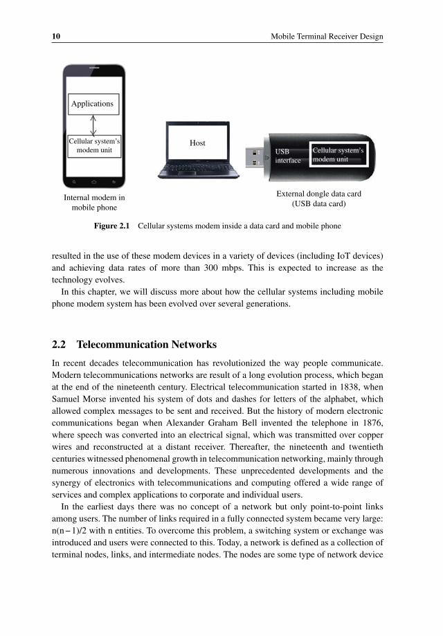
A modem is an electronic device that helps to modulate and demodulate the information at the transmitter and receiver block respectively in order to transmit the information signal reliably through the propagating medium. The word “modem” came from the term “ modulator‐demodulator.” The modulator unit takes a baseband (low‐rate / frequency) signal as input and converts it into a high‐rate / frequency‐modulated signal as output. If the baseband information signal is analog, then analog modulations, like AM, FM, and PM are used, otherwise if the baseband signal is digital then digital modulations like ASK, FSK, and PSK are used in the modulator to produce a low‐frequency analog signal, which is later converted to a high‐frequency RF signal before transmission through the medium. Initially a modem was also known as “data phone,” as it enabled a computer terminal (host) to send and receive information over telephone lines (PSTN) by converting the digital data of a computer terminal into an analog signal used on telephone phone lines and then converting it back to its original form once it was received at the other end. These modems are com‑monly known as “dialup modems.” Wireless modems work in the same way as a dialup analog modem, except they convert digital data into radio signals for transmission through air. The cellular systems modem is also wireless modem used in cellular networks and reside inside a cellular mobile terminal, as shown in Figure 1.2. Today, this modem unit can be integrated inside a mobile phone or it is used in a dongle data card and connected to the host PC device via USB or other interfaces as shown in Figure 2.1. The evolution of the modem over a cellular wireless network has occurred at a much more rapid pace,
2
10 Mobile Terminal Receiver Design
resulted in the use of these modem devices in a variety of devices (including IoT devices) and achieving data rates of more than 300 mbps. This is expected to increase as the technology evolves.
In this chapter, we will discuss more about how the cellular systems including mobile phone modem system has been evolved over several generations.
2.2 Telecommunication Networks
In recent decades telecommunication has revolutionized the way people communicate. Modern telecommunications networks are result of a long evolution process, which began at the end of the nineteenth century. Electrical telecommunication started in 1838, when Samuel Morse invented his system of dots and dashes for letters of the alphabet, which allowed complex messages to be sent and received. But the history of modern electronic communications began when Alexander Graham Bell invented the telephone in 1876, where speech was converted into an electrical signal, which was transmitted over copper wires and reconstructed at a distant receiver. Thereafter, the nineteenth and twentieth centuries witnessed phenomenal growth in telecommunication networking, mainly through numerous innovations and developments. These unprecedented developments and the synergy of electronics with telecommunications and computing offered a wide range of services and complex applications to corporate and individual users.
In the earliest days there was no concept of a network but only point‐to‐point links among users. The number of links required in a fully connected system became very large: n(n − 1)/2 with n entities. To overcome this problem, a switching system or exchange was introduced and users were connected to this. Today, a network is defined as a collection of terminal nodes, links, and intermediate nodes. The nodes are some type of network device
Host
Applications
Cellular system’smodem unit Cellular system’s
modem unit
Internal modem inmobile phone
External dongle data card(USB data card)
USBinterface
Figure 2.1 Cellular systems modem inside a data card and mobile phone
Cellular Systems Modems 11
and may either be data communication equipment (DCE), such as a modem, hub, bridge, or switch, or data terminal equipment (DTE) such as a digital telephone handset, a host computer, a router, workstation, or server. The links are the means through which the nodes communicate with each other, like copper cables, optical fiber, or radio waves.
Generally, the three main mechanisms through which the communication takes place are (i) transmission, (ii), switching, and (iii) signaling.
• Transmission is the process of transporting information between two end terminals in the network. Generally, transmission systems use four basic media for information transfer: copper cables, optical fiber cables, radio waves (air), and free‐space optics.
• Switching is required to establish the appropriate signal flow path between two commu‑nicating terminals. The nodes use circuit switching, message switching, or packet switch‑ing to pass the signal through the correct links and nodes to reach the correct destination terminal. In circuit switching the network reserves a dedicated channel (fixed bandwidth) for the entire communication duration as if nodes were physically connected, keeping the bit delay constant. In message switching the message is sent to the nearest directly connected switching node, which then checks for errors, selects the best available route and forwards the message to the next intermediate node. Each node stores the full message, checks for errors and forwards it, so this method is also known as the “store‐and‐forward” method. Packet switching also uses the store‐and‐forward mechanism but here the message is broken into small series of packets and then routed between nodes over data links shared with other traffic. Two major packet switching modes are connectionless and connection‐oriented packet switching. In connectionless switching each packet has complete addressing or routing information and is routed individually, which sometimes results in out‐of‐order delivery. In the case of connection‐oriented packet switching, a connection is defined and preallocated in the connection setup phase, before any packet is transferred.
• Signaling is the mechanism that allows network entities to establish, maintain, and terminate communication sessions in a network.
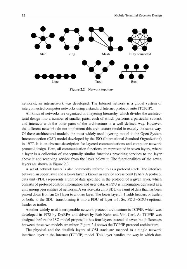
A logical model that describes how networks are structured or configured and describes how network nodes are interconnected is known as network topology. Various network topologies used today. These are shown in Figure 2.2.
Today, there are several basic types of telecommunications networks in use like, public switched telecommunications networks (PSTNs), cellular networks, computer networks, the Internet network, and the global Telex network. PSTN provides a traditional plain old telephone service (POTS), which relies on circuit switching to connect one phone to another via complex interconnection through a variety of heterogeneous switching sys‑tems. A cellular network is a wireless network deployed over cellular structure as explained in detail in section 2.3. A computer network is data network that allows computers to exchange data mainly in the form of packets. It can range from a local area network (LAN) to a wide area network (WAN), based on the size. As there was a need to interconnect these
12 Mobile Terminal Receiver Design
networks, an internetwork was developed. The Internet network is a global system of interconnected computer networks using a standard Internet protocol suite (TCP/IP).
All kinds of networks are organized in a layering hierarchy, which divides the architec‑tural design into a number of smaller parts, each of which performs a particular subtask and interacts with the other parts of the architecture in a well defined way. However, the different networks do not implement this architecture model in exactly the same way. Of these architectural models, the most widely used layering model is the Open System Interconnection (OSI) model developed by the ISO (International Standard Organization) in 1977. It is an abstract description for layered communications and computer network protocol design. Here, all communication functions are represented in seven layers, where a layer is a collection of conceptually similar functions providing services to the layer above it and receiving service from the layer below it. The functionalities of the seven layers are shown in Figure 2.3.
A set of network layers is also commonly referred to as a protocol stack. The interface between an upper layer and a lower layer is known as service access point (SAP). A protocol data unit (PDU) represents a unit of data specified in the protocol of a given layer, which consists of protocol control information and user data. A PDU is information delivered as a unit among peer entities of networks. A service data unit (SDU) is a unit of data that has been passed down from an OSI layer to a lower layer. The lower layer, n‐1, adds headers or trailer, or both, to the SDU, transforming it into a PDU of layer n‐1. So, PDU = SDU + optional header or trailer.
Another widely used interoperable network protocol architecture is TCP/IP, which was developed in 1978 by DARPA and driven by Bob Kahn and Vint Cerf. As TCP/IP was designed before the ISO model proposal it has four layers instead of seven but differences between these two models are minor. Figure 2.4 shows the TCP/IP protocol architecture.
The physical and the datalink layers of OSI stack are mapped to a single network interface layer in the Internet (TCP/IP) model. This layer handles the way in which data
Star Ring Mesh Fully connected
Line Tree Bus
Figure 2.2 Network topology


