i MOBILE WIMAX: PRE-HANDOVER OPTIMIZATION USING HYBRID BASE STATION SELECTION PROCEDURE A thesis submitted in partial fulfilment of the requirements for the Degree of Master of Engineering in Electrical and Computer Engineering in the University of Canterbury by Arpan Mandal University of Canterbury 2008
Transcript
i
MOBILE WIMAX: PRE-HANDOVER
OPTIMIZATION USING HYBRID BASE
STATION SELECTION PROCEDURE
A thesis submitted in partial fulfilment of the
requirements for the Degree
of Master of Engineering in Electrical and Computer
2.3 BROAD INTRODUCTION TO RESEARCH AREA................................................... 19 2.4 SUMMARY ......................................................................................................... 21
3 HANDOVER IN WIRELESS TECHNOLOGIES.............................................. 22 3.1 WHY HANDOVER? ............................................................................................ 22 3.2 TYPES OF HANDOVER ....................................................................................... 23 3.3 STAGES OF HANDOVER..................................................................................... 28
3.3.1 Handover Initiation ..................................................................................... 28 3.3.1.1 Relative Signal Strength................................................................................. 29 3.3.1.2 Relative Signal Strength with Threshold....................................................... 30 3.3.1.3 Relative Signal Strength with Hysteresis ...................................................... 30 3.3.1.4 Relative Signal Strength with Hysteresis and Threshold.............................. 31 3.3.1.5 Prediction Techniques.................................................................................... 31
Figure 1. PSTN and WiMAX............................................................................. 3 Figure 2. Types of networks............................................................................. 13 Figure 3. WiMAX Protocol Stack.................................................................... 15 Figure 4. Inter-cell and Intra- cell handover..................................................... 25 Figure 5. Hard Handover between the MSS and BSs...................................... 27 Figure 6. Signal strength and hysteresis between two BSs (potential
handover) .............................................................................................. 29 Figure 7. MAC Layer Handover Procedure..................................................... 38 Figure 8. MSS initiated HO as seen by MSS................................................... 41 Figure 9. MSS initiated HO as seen by the SBS.............................................. 42 Figure 10. Example of Scanning ...................................................................... 46 Figure 11. Hard Handover in WiMAX ............................................................ 48 Figure 12. Simulated Network Topology (6BSs, 18 SSs) ............................... 50 Figure 13. Proposed optimization along with Hybrid BS selection
procedure .............................................................................................. 58 Figure 14. Hybrid BS selection procedure....................................................... 59 Figure 15. Scanning Time Vs Instances of MOB_SCN_REP messages ........ 69 Figure 16. Further optimization prior to MSS release ..................................... 70
iv
Acknowledgments
The research undertaken would not have been possible without the
guidance and assistance I have been able to enjoy.
Firstly, I would like to thank my thesis supervisor Professor Harsha
Sirisena, for providing me the right balance of guidance and independence
in my research. I am immensely indebted to him for his advice both in
technical and non-technical matters. He has always been willing to take the
time to help me and offer advice. I am also grateful to my co-supervisor,
Dr Kishore Mehrotra for his great support, especially towards the initial
stages of giving a shape to the research idea. Special thanks to Professor
Krzysztof Pawlikowski from the Dept of Comuter Science for his valuable
input.
I would like to extend many thanks to my colleagues at the Network
Research Group, especially Mr. Sayan K. Ray for the time spent together
and the knowledge we have been sharing. We presented a research paper
together and it has been a morale booster for me. I am also grateful to my
friends and staff members at the University of Canterbury for their
continuous support and encouragement. I would specially wish to thank
Pieter Kilstra and Florin Predan for their prompt response for any system
problems. Without their support, it would have been an uphill task to do
my work.
v
My special thanks go to my parents and parents-in-laws for their trust and
prayers. I would like to acknowledge the dedication and sacrifice of my
wife and daughter. The thesis would have never been completed without
her presence beside me.
vi
Abstract
A major consideration for mobile WiMAX is seamless handoff. The
British English term for transferring a cellular call is handover whereas
the Americans prefer to call it handoff. Cellular-based standards have the
advantage of many years experience in handover for voice calls, while for
broadband mobility in itself is no mean feat, and handover is still a
challenge. Mobile IP, with “slow” handover, will be fine for web-browsing
but not good enough for decent voice quality. Many services require the
appearance of seamless connections (VoIP, VPNs, etc). Much of the
complexity (and latency) in the cellular network is from maintaining these
connections across cell boundaries. Handovers in wireless technologies
have always been a challenging topic of discussion.
According to the mobility framework of IEEE 802.16e, a Mobile Station
(MSS) should scan the neighbouring Base Stations (BSs) for selecting the
best BS for a potential handover. However, the standard does not specify
the number of BSs to be scanned leaving room for unnecessary scanning.
Moreover, prolonged scanning also interrupts data transmissions thus
degrading the QoS of an ongoing connection. Reducing unnecessary
scanning is an important issue. This thesis proposes a scheme to reduce the
number of BSs to scan, thus improving the overall handover performance.
Simulation results show that the proposed hybrid predictive BS selection
scheme for potential scanning activities is more effective than the
vii
conventional IEEE 802.16e handover scheme in terms of handover delay
and resource wastage.
Before the actual handover process, there is scope of reducing the total
number of iterations of message exchanges occurring between the mobile
MSS, the SBS and the neighbouring BSs which are potential targets for
handover. Simulations prove that it takes upto 700 ms to decide the target
BS before initiating the handover process with it. There are multiple
message exchanges to choose a set of potential target BSs from all the
neighbouring BSs. A few more messages flow between the MSS, SBS and
potential target BSs to choose the best candidate BS for handover. The
many stages and messages waste time and could be reduced. This thesis
discusses some ways to reduce them and backs it up with simulation
results.
viii
Acronyms
ASN Access Services Network ASN-GW Access Services Network - Gateway BE Best Effort BS Base Station CBR Constant Bit Rate CPE Customer Premise Equipment CSN Connectivity Services Network DCD Downlink channel descriptor DL Down Link FBSS Fast base station switching IPv4 IP IPv6 IP LOS Line of Sight MAC Medium Access Control MDHO Macro diversity handover MSC Mobile Switching Centre MSS Mobile Subscriber Station NLOS Non Line Of Sight NWG Network Working Group (WiMAX Forum) OFDMA Orthogonal Frequency Division Multiple Access PHY Physical QoS Quality of Service RSSI Received Signal Strength Indication SBS Serving Base Station SS Subscriber Station TBS Target Base Station UCD Uplink channel descriptor UL Uplink
1
1 Introduction
1.1 Background
Since the inception of the telephone, service providers have staved off
competition by relying on the exorbitant capital investment necessary to
deploy a telephone network. The cost of deploying copper wires, building
switches, and connecting the switches created an insurmountable barrier to
entry for other competitors. In most of the world, the high cost of this
infrastructure limited telephone service to the wealthy and the fledging middle
class.
The Public Switched Telephone Network (PSTN) was the earliest example of
traffic engineering to deliver Quality of Service (QoS) guarantees. It consists
of three major components: access, switching and transport. Each element has
evolved over the hundred years plus history of the PSTN. This network was
designed originally to handle voice; later, data was introduced. As data traffic
on the PSTN grew, high capacity users found it inadequate, so these
subscribers moved their data traffic to data specific networks. Many data users
then found themselves limited to an infrastructure that was dependent on
wires, either fiber optic cable, coaxial cable or twisted pair copper wire. Using
wireless means to bypass wired monopolies is now a practicality for
2
subscribers of both voice and data services. The primary form of bypass is the
use of cellular phones.
A cellular network is a radio network made up of a number of radio cells (or
just cells) each served by a fixed transmitter, known as a cell site or base
station. These cells are used to cover different areas in order to provide radio
coverage over a wider area than the area of one cell. Cellular networks are
inherently asymmetric with a set of fixed main transceivers each serving a cell
and a set of distributed (generally, but not always, mobile) transceivers which
provide services to the network's users. Cellular networks offer a number of
advantages over alternative solutions such as increased capacity, reduced
power usage, better coverage etc.
The use of multiple cells means that, if the distributed transceivers are mobile
and moving from place to place, they also have to change from cell to cell.
The mechanism for this differs depending on the type of network and the
circumstances of the change. For example, if there is an ongoing continuous
communication and we don't want to interrupt it, then great care must be taken
to avoid interruption. In this case there must be clear coordination between the
base station and the mobile station.
3
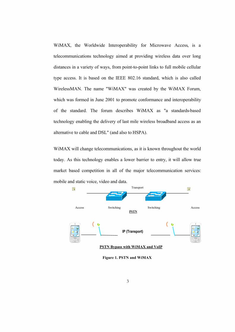
WiMAX, the Worldwide Interoperability for Microwave Access, is a
telecommunications technology aimed at providing wireless data over long
distances in a variety of ways, from point-to-point links to full mobile cellular
type access. It is based on the IEEE 802.16 standard, which is also called
WirelessMAN. The name "WiMAX" was created by the WiMAX Forum,
which was formed in June 2001 to promote conformance and interoperability
of the standard. The forum describes WiMAX as "a standards-based
technology enabling the delivery of last mile wireless broadband access as an
alternative to cable and DSL" (and also to HSPA).
WiMAX will change telecommunications, as it is known throughout the world
today. As this technology enables a lower barrier to entry, it will allow true
market based competition in all of the major telecommunication services:
mobile and static voice, video and data.
Figure 1. PSTN and WiMAX
Transport
Switching Switching Access Access PSTN
IP (Transport)
PSTN Bypass with WiMAX and VoIP
IP (Transport)
PSTN Bypass with WiMAX and VoIP
4
1.2 Motivation
In IEEE 802.16e standard, the total handover occurs in phases. Network
Topology Acquisition Phase (NTAP) and the Actual Handover Phase (AHOP)
are the two main phases.
During the NTAP, the MSS performs scanning and downlink synchronization
activities with the advertised neighboring BSs to select a new target BS to
perform the handover activity.
During the AHOP, the MSS releases its connection with the current SBS and
performs synchronization, registration procedures with the newly selected
target BS to successfully complete the handover process. However, the entire
procedure is not free from ambiguities. Excessive scanning and
synchronization activities may result in unwanted handover delays along with
wastages of valuable resources. Hence, limiting the extent of scanning
activities remains a challenging task in the IEEE 802.16e systems.
During the scanning procedure all uplink and downlink traffic is stalled or
buffered. For delay sensitive traffic like VoIP and video bitstream, such a
phenomenon is disruptive. On careful analysis, it takes a few hundred
milliseconds of time to decide the best candidate BS for handover. There is
5
scope of improvement of the steps involved in both the phases of the BS
selection procedure.
1.3 Research Objectives
• Survey problem areas in handover schemes in Mobile WiMAX (IEEE
802.16e)
• Focus on time consuming processes
• Analyze the performance of the standard procedure
• Introduce an innovative Base Station selection procedure for handover
considering other factors apart from the standard.
• Optimize the target BS decision phases and reduce the overall time
taken
• Survey a host of WiMAX simulators widely used in academic and
industrial areas and select one for procurement.
• Simulate the standard WiMAX handover procedure and the proposed
algorithms.
• Present analysis results.
6
1.4 Structure
This section provides an overview of the thesis structure and discusses the
main points of each chapter briefly.
Chapter 2 presents an overview of different communication methods and
introduces the topic of WiMAX. It presents a bird’s eye view of the
technology and performance metrics. It ends with a broad introduction of the
research area.
Chapter 3 provides more detail about wireless handovers in general. It
discusses the types, stages and the need for handover
Chapter 4 discusses the handover procedure as described in the IEEE 802.16e
standard. It describes the WiMAX mobility management architecture.
Chapter 5 describes the proposed scheme against the backdrop of the existing
standard procedure. It describes the implementation, the simulation scenario,
the assumptions considered to simulate and the results.
Chapter 6 draws conclusion from the results achieved in the last chapter. It
also presents ideas that might help the reader to carry out future research work
in the area.
7
2 WiMAX Technology
2.1 Background of WiMAX
WiMAX (also known as IEEE 802.16) is a wireless digital communications
system that is intended for wireless "metropolitan area networks" (WMAN).
It can provide broadband wireless access (BWA) up to 30 miles (50 km) for
fixed stations, and 3 - 10 miles (5 - 15 km) for mobile stations. In contrast, the
WiFi/802.11 wireless local area network standard is limited in most cases to
only 100 - 300 feet (30 - 100m).
WiFi-like data rates are easily supported in WiMAX, but the issue of
interference is less. Operating on both licensed and non-licensed frequencies,
it provides a regulated environment and a viable economic model for wireless
carriers.
WiMAX can be used for wireless networking in much the same way as the
WiFi protocol. WiMAX is a second-generation protocol that allows for more
efficient bandwidth use, interference avoidance, and is intended to allow
higher data rates over longer distances.
The IEEE 802.16 standard defines the technical features of the
communications protocol. The WiMAX Forum offers a means of testing
8
manufacturer's equipment for compatibility, as well as an industry group
dedicated to fostering the development and commercialization of the
technology. Soon, WiMAX will be a very well recognized term to describe
wireless Internet access all over the world.
The IEEE 802.16 group was formed in 1998 to develop an air-interface
standard for wireless broadband. The group's initial focus was the
development of a LOS-based point-to-multipoint wireless broadband system
for operation in the 10GHz–66GHz millimeter wave band. The resulting
standard—the original 802.16 standard, completed in December 2001—was
based on a single-carrier physical (PHY) layer with a burst time division
multiplexed (TDM) MAC layer. Many of the concepts related to the MAC
layer were adapted for wireless from the popular cable modem DOCSIS (data
over cable service interface specification) standard.
The IEEE 802.16 group subsequently produced 802.16a, an amendment to the
standard, to include NLOS applications in the 2GHz–11GHz band, using an
orthogonal frequency division multiplexing (OFDM)-based physical layer.
Additions to the MAC layer, such as support for orthogonal frequency division
multiple access (OFDMA), were also included. Further revisions resulted in a
new standard in 2004, called IEEE 802.16-2004, which replaced all prior
versions and formed the basis for the first WiMAX solution. These early
9
WiMAX solutions based on IEEE 802.16-2004 targeted fixed applications,
and these will be referred to as fixed WiMAX [19]. In December 2005, the
IEEE group completed and approved IFEEE 802.16e-2005, an amendment to
the IEEE 802.16-2004 standard that added mobility support. The IEEE
802.16e-2005 forms the basis for the WiMAX solution for nomadic and
mobile applications and is often referred to as mobile WiMAX [18].
Note that these standards offer a variety of fundamentally different design
options. For example, there are multiple physical-layer choices: a single-
carrier-based physical layer called WirelessMAN-SCa, an OFDM-based
physical layer called WirelessMAN-OFDM, and an OFDMA- based physical
layer called Wireless-OFDMA. Similarly, there are multiple choices for MAC
architecture, duplexing, frequency band of operation, etc. These standards
were developed to suit a variety of applications and deployment scenarios, and
hence offer a plethora of design choices for system developers. In fact, one
could say that IEEE 802.16 is a collection of standards, not one single
interoperable standard.
With the completion of the IEEE 802.16e-2005 standard, interest within the
WiMAX group has shifted sharply toward developing and certifying mobile
WiMAX[18] system profiles based on this newer standard. All mobile
WiMAX profiles use scalable OFDMA as the physical layer. At least initially,
10
all mobility profiles will use a point-to-multipoint MAC. It should also be
noted that all the current candidate mobility certification profiles are TDD
based. Although TDD is often preferred, FDD profiles may be needed for in
the future to comply with regulatory pairing requirements in certain bands.
For the reminder of this chapter, the focus is solely on WiMAX and therefore
only aspects of IEEE 802.16 family of standards that may be relevant to
current and future WiMAX certification are discussed. It should be noted that
the IEEE 802.16e-2004 and IEEE 802.16-2005 standards specifications are
limited to the control and data plane aspects of the air-interface. Some aspects
of network management are defined in IEEE 802.16g. For a complete end-to-
end system, particularly in the context of mobility, several additional end-to-
end service management aspects need to be specified. This task is being
performed by the WiMAX Forums Network Working Group (NWG). The
WiMAX NWG is developing an end-to-end network architecture and filling in
some of the missing pieces.
11
2.2 WiMAX basics
2.2.1 Introduction
Internet is the preferred mode of communication today. There are basically
three different options of accessing the internet:
Broadband access - In your home, you have either a DSL or cable modem. At
the office, your company may be using a T1 or a T3 line.
WiFi access - In your home, you may have set up a WiFi router that lets you
surf the Web while you lounge with your laptop. On the road, you can find
WiFi hot spots in restaurants, hotels, coffee shops and libraries.
Dial-up access - If you are still using dial-up, chances are that either
broadband access is not available, or you think that broadband access is too
expensive.
All of these options have got their own problems as well. Broadband access is
pretty expensive and it doesn't reach all areas. The main trouble with WiFi
access is that hot spots are very small, so thin coverage.
What if there was a new technology that solved all of these problems? This
new technology would provide:
12
• The high speed of broadband service
• Broad coverage like the cell phone network (against small WiFi hotspots)
• Wireless rather than wired access, so it would be a lot cheaper than cable or DSL and much easier to extend to suburban and rural areas
This system is actually being developed and tested right now in various parts
of the world, and it is called WiMAX (short for Worldwide Interoperability for
Microwave Access, and it also goes by the IEEE name 802.16).
The smallest-scale network is a personal area network (PAN). A PAN allows
devices to communicate with each other over short distances. Bluetooth is the
best example of a PAN.
The next step up is a local area network (LAN). A LAN allows devices to
share information, but is limited to a fairly small central area, such as a
company's headquarters, a coffee shop or your house. Many LANs use WiFi to
connect the network wirelessly.
WiMAX is the wireless solution for the next step up in scale, the metropolitan
area network (MAN). A MAN allows areas the size of cities to be connected.
WiMAX has the potential to do to broadband Internet access what cell phones
have done to phone access. In the same way that many people have given up
their "land lines" in favor of cell phones, WiMAX could replace cable and
13
DSL services, providing universal Internet access just about anywhere you go.
WiMAX will also be as painless as WiFi -- turning your computer on will
automatically connect you to the closest available WiMAX antenna.
Figure 2. Types of networks
2.2.2 Operating Principles
A WiMAX system consists of two parts:
• A WiMAX tower, similar in concept to a cell-phone tower - A single
WiMAX tower can provide coverage to a very large area -- as big as
8,000 square kilometers (~3,000 square miles).
• A WiMAX receiver - The receiver and antenna could be a small box or
PCMCIA card, or they could be built into a laptop the way WiFi
access is today.
A WiMAX tower station can connect directly to the Internet using a high-
bandwidth, wired connection (for example, a T3 line). It can also connect to
another WiMAX tower using a line-of-sight, microwave link. This connection
to a second tower (often referred to as a backhaul), along with the ability of a
Metropolitan Area Network IEEE 802.16 Connects devices upto (MAN) 50 km radius (approx)
Local Area Network IEEE 802.11 Connects devices upto (LAN) 300 ft radius (approx)
Personal Area Network IEEE 802.15 Connects devices upto (PAN) 33 ft radius (approx)
14
single tower to cover up to 3,000 square miles, is what allows WiMAX to
provide coverage to remote rural areas.
What this means is that WiMAX actually can provide two forms of wireless
service. There is the non-line-of-sight (NLOS), WiFi sort of service, where a
small antenna on your computer connects to the tower. In this mode, WiMAX
uses a lower frequency range -- 2 GHz to 11 GHz (similar to WiFi). Lower-
wavelength transmissions are not as easily disrupted by physical obstructions -
- they are better able to diffract, or bend, around obstacles.
There is line-of-sight service (LOS), where a fixed dish antenna points straight
at the WiMAX tower from a rooftop or pole. The line-of-sight connection is
stronger and more stable, so it's able to send a lot of data with fewer errors.
Line-of-sight transmissions use higher frequencies, with ranges reaching a
possible 66 GHz. At higher frequencies, there is less interference and lots
more bandwidth.
WiFi-style access will be limited to a 4-to-6 mile radius (perhaps 25 square
miles or 65 square km of coverage, which is similar in range to a cell-phone
zone). Through the stronger line-of-sight antennas, the WiMAX transmitting
station would send data to WiMAX-enabled computers or routers set up within
15
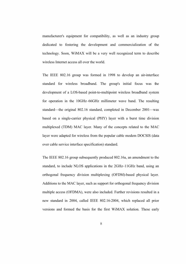
the transmitter's 30-mile radius (2,800 square miles or 9,300 square km of
coverage). This is what allows WiMAX to achieve its maximum range.
Figure 3. WiMAX Protocol Stack
2.2.3 Usage
WiMAX operates on the same general principles as WiFi -- it sends data from
one computer to another via radio signals. A computer (either a desktop or a
laptop) equipped with WiMAX would receive data from the WiMAX
16
transmitting station, probably using encrypted data keys to prevent
unauthorized users from stealing access.
The fastest WiFi connection can transmit up to 54 megabits per second under
optimal conditions. WiMAX should be able to handle up to 70 megabits per
second. Even once that 70 megabits is split up between several dozen
businesses or a few hundred home users, it will provide at least the equivalent
of cable-modem transfer rates to each user.
The biggest difference isn't speed; it's distance. WiMAX outdistances WiFi by
miles. WiFi's range is about 100 feet (30 m). WiMAX will blanket a radius of
30 miles (50 km) with wireless access. The increased range is due to the
frequencies used and the power of the transmitter. Of course, at that distance,
terrain, weather and large buildings will act to reduce the maximum range in
some circumstances, but the potential is there to cover huge tracts of land.
In an emergency, communication is crucial for government officials as they try
to determine the cause of the problem, find out who may be injured and
coordinate rescue efforts or cleanup operations. A gas-line explosion or
terrorist attack could sever the cables that connect leaders and officials with
their vital information networks.
17
WiMAX could be used to set up a back-up (or even primary) communications
system that would be difficult to destroy with a single, pinpoint attack. A
cluster of WiMAX transmitters would be set up in range of a key command
center but as far from each other as possible. Each transmitter would be in a
bunker hardened against bombs and other attacks. No single attack could
destroy all of the transmitters, so the officials in the command center would
remain in communication at all times.
2.2.4 Applicability
It depends how it will be used. There are two ways WiMAX can be
implemented -- as a zone for wireless connections that single users go to when
they want to connect to the Internet on a laptop (the non-line-of-sight "super
WiFi" implementation), or as a line-of-sight hub used to connect hundreds of
customers to a steady, always-on, high-speed wireless Internet connection.
Under the "super WiFi" plan, cities might pay to have WiMAX base stations
set up in key areas for business and commerce and then allow people to use
them for free. They already do this with WiFi, but instead of putting in a
bunch of WiFi hot spots that cover a few hundred square yards, a city could
pay for one WiMAX base station and cover an entire financial district. This
could provide a strong draw when city leaders try to attract businesses to their
area.
18
Some companies might set up WiMAX transmitters and then make people pay
for access. Again, this is similar to strategies used for WiFi, but a much wider
area would be covered. Instead of hopping from one hot spot to another,
WiMAX-enabled users could have Internet access anywhere within 30 miles
of the WiMAX base station. These companies might offer unlimited access for
a monthly fee or a "pay as you go" plan that charges on a per-minute or per-
hour basis.
The high-speed wireless hub plan has the potential to be far more
revolutionary. If you have high-speed Internet access now, it probably works
something like this: The cable (or phone) company has a line that runs into
your home. That line goes to a cable modem, and another line runs from the
modem to your computer. If you have a home network, first it goes to a router
and then on to the other computers on the network. You pay the cable
company a monthly fee, which reflects in part the expense of running cable
lines to every single home in the neighborhood.
WiMAX doesn't just pose a threat to providers of DSL and cable-modem
service. The WiMAX protocol is designed to accommodate several different
methods of data transmission, one of which is Voice Over Internet Protocol
(VoIP). VoIP allows people to make local, long-distance and even
international calls through a broadband Internet connection, bypassing phone
19
companies entirely. If WiMAX-compatible computers become very common,
the use of VoIP could increase dramatically. Almost anyone with a laptop
could make VoIP calls.
2.3 Broad Introduction to Research Area
Mobility is the most important feature of a wireless cellular communication
system. Usually, continuous service is achieved by supporting handover (or
handover) from one cell to another. The IEEE standard 802.16e-2005 provides
enhancements to IEEE standard 802.16-2004 to support subscriber stations
(SS) moving at vehicular speeds. It thereby specifies a system for combined
fixed and mobile broadband wireless access without compromising the
capabilities of fixed IEEE 802.16 subscribers. Functions to support handover
at higher layers between base stations are specified. Operation is limited to
licensed bands suitable for mobility below 6 GHz.
Vertical handover refers to handover from one technology to another in order
to maintain communication. This involves changing the data link layer
technology used to access the network. Thus it is different from a horizontal
handover between different wireless access points or base stations (BS) that
use the same technology.
20
In traditional handoffs, such as a handoff between cellular networks, the
handoff decision is based mainly on RSS (Relative Signal Strength) in the
border region of two cells, and may also be based on call drop rate, etc. for
resource management reasons. In vertical handoff, the situation is more
complex. Two different kinds of wireless networks normally have
incomparable signal strength metrics, for example, WLAN compared to
UMTS. In, WLAN and UMTS networks both cover an area at the same time.
The Handoff Metrics in this situation should include RSS, user preference,
network conditions, application types, cost etc.
One of the most challenging research issues of investigating broadband
wireless access (BWA) technologies such as WiMAX is how to support
mobility smoothly and seamlessly. It is essential to provide continuous
services of multimedia streaming data when a mobile subscriber station (MSS)
undergoes handover. Although the IEEE 802.16e standard proposes to tackle
this problem, the disruption time (DT) of handover is still too long to
overcome the maximum delay time of real-time services such as VoIP and
video bit streaming.
21
2.4 Summary
WiMAX™ is based upon the IEEE 801.16 standard enabling the delivery of
wireless broadband services anytime, anywhere. WiMAX products can
accommodate fixed and mobile usage models. The IEEE 802.16 standard was
developed to deliver non-line-of-sight (LoS) connectivity between a subscriber
station and base station with typical cell radius of three to ten kilometers. All
base stations and subscriber stations claiming to be WiMAX compliant must
go through a rigorous WiMAX Forum Certified™ testing process. WiMAX
Forum Certified systems can be expected to deliver capacity of up to 40 Mbps
per channel. This is enough bandwidth to simultaneously support hundreds of
businesses with T-1 speed connectivity and thousands of residences with DSL
speed connectivity. The WiMAX Forum expects mobile network deployments
to provide up to 15 Mbps of capacity within a typical cell radius of up to three
kilometers.
22
3 Handover in Wireless
Technologies
3.1 Why Handover?
In cellular telecommunications, the term handover refers to the process of
transferring an ongoing call or data session from one channel connected to the
core network to another.
There may be different reasons why a handover might be conducted:
• when the phone is moving away from the area covered by one cell and
entering the area covered by another cell the call is transferred to the
second cell in order to avoid call termination when the phone gets
outside the range of the first cell;
• when the capacity for connecting new calls of a given cell is used up
and an existing or new call from a phone, which is located in an area
overlapped by another cell, is transferred to that cell in order to free-up
some capacity in the first cell for other users, who can only be
connected to that cell;
• in non-CDMA networks when the channel used by the phone becomes
interfered with by another phone using the same channel in a different
23
cell, the call is transferred to a different channel in the same cell or to a
different channel in another cell in order to avoid the interference;
• again in non-CDMA networks when the user behaviour changes, e.g.
when a fast-travelling user, connected to a large, umbrella-type of cell,
stops then the call may be transferred to a smaller macro-cell or even to
a micro-cell in order to free capacity on the umbrella cell for other fast-
travelling users and to reduce the potential interference to other cells or
users (this works in reverse too, when a user is detected to be moving
faster than a certain threshold, the call can be transferred to a larger
umbrella-type of cell in order to minimise the frequency of the
handovers due to this movement);
• in CDMA networks a soft handover may be induced in order to reduce
the interference to a smaller neighbouring cell due to the "near-far"
effect even when the phone still has an excellent connection to its
current cell;
3.2 Types of Handover
Handovers are broadly classified into two categories—hard and soft
handovers. Usually, the hard handover can be further divided into two
24
different types—intra- and inter- cell handovers. The soft handover can also
be divided into two different types—multiway soft handovers and softer
handovers. In this thesis work, the focus is primarily on the hard handover.
A hard handover is essentially a “break before make” connection. Under the
control of the MSC (Mobile Switching Centre), the BS hands over the MSS’s
call to another cell and then drop the call. In a hard handover, the link to the
prior BS is terminated before or as the user is transferred to the new cell’s BS;
the MSS is linked to no more than one BS at any given time. Hard handover is
primarily used in FDMA (frequency division multiple access) and TDMA
(time division multiple access), where different frequency ranges are used in
adjacent channels in order to minimize channel interference. So when the MSS
moves from one BS to another BS, it becomes impossible for it to
communicate with both BSs (since different frequencies are used). The figure
below illustrates hard handover between the MSS and the BSs.
Intra cell/domain handover refers to handover occurring when a MSS moves
from the vicinity of one BS to another BS within the same operator or
backbone (referred to as (A) in the next figure). Inter cell/domain handover
refers to a similar activity where the BSs are from different operators or
backbones (referred to as (B) in the figure 4).
25
Figure 4. Inter-cell and Intra- cell handover
An advantage of the hard handover is that at any moment in time one call uses
only one channel. The hard handover event is indeed very short and usually is
not perceptible by the user. In the old analog systems it could be heard as a
click or a very short beep, in digital systems it is unnoticeable. Another
advantage of the hard handover is that the phone's hardware does not need to
be capable of receiving two or more channels in parallel, which makes it
cheaper and simpler. A disadvantage is that if a handover fails the call may be
Gateway Operator ‘X’ backbone network
Operator ‘Y’ backbone network
BS 1
BS 2
BS 5
MSS
MSS
MSS
Backhaul connection
A
B
26
temporarily disrupted or even terminated abnormally. Technologies, which
utilize hard handovers, usually have procedures which can re-establish the
connection to the source cell if the connection to the target cell cannot be
made. However re-establishing this connection may not always be possible (in
which case the call will be terminated) and even when possible the procedure
may cause a temporary interruption to the call.
One advantage of the soft handovers is that the connection to the source cell is
broken only when a reliable connection to the target cell has been established
and therefore the chances that the call will be terminated abnormally due to a
failed handover are lower. However, by far a bigger advantage comes from the
mere fact that simultaneously channels in multiple cells are maintained and the
call could only fail if all of the channels are interfered or fade at the same time.
Fading and interference in different channels are unrelated and therefore the
probability of them taking place at one the same moment in all channels is
very low. Thus the reliability of the connection becomes higher when the call
is in a soft handover.
BS 1 BS 2
27
Figure 5. Hard Handover between the MSS and BSs Because in a cellular network the majority of the handovers occur in places of
poor coverage, where calls would frequently become unreliable when their
channel is interfered with or fading, soft handovers bring a significant
improvement to the reliability of the calls in these places by making the
interference or the fading in a single channel not critical.
MSS
Before Handover
BS 1 BS 2
MSS
After Handover
28
This advantage comes at the cost of more complex hardware in the phone,
which must be capable of processing several channels in parallel. Another
price to pay for soft handovers is the use of several channels in the network to
support just a single call. This reduces the number of remaining free channels
and thus reduces the capacity of the network. By adjusting the duration of soft
handovers and the size of the areas, in which they occur, the network
engineers can balance the benefit of extra call reliability against the price of
reduced capacity.
3.3 Stages of Handover
3.3.1 Handover Initiation
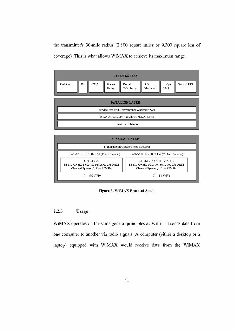
A hard handover occurs when the old connection is broken before a new
connection is activated. The performance evaluation of a hard handover is
based on various initiation criteria. It is assumed that the signal is averaged
over time, so that rapid fluctuations due to the multipath nature of the radio
environment can be eliminated. Numerous studies have been done to
determine the shape as well as the length of the averaging window and the
older measurements may be unreliable. The next figure shows a MSS moving
from one BS (BS1) to another (BS2). The mean signal strength of BS1
decreases as the MSS moves away from it. Similarly, the mean signal strength
29
of BS2 increases as the MSS approaches it. This figure is used to explain
various approaches described in the following subsection.
Figure 6. Signal strength and hysteresis between two BSs (potential handover)
3.3.1.1 Relative Signal Strength
This method selects the strongest received BS at all times. The decision is
based on a mean measurement of the received signal. In Figure 6, the
handover would occur at position A. This method is observed to provoke too
many unnecessary handovers, even when the signal of the current BS is still at
an acceptable level.
Signal Strength
Sign
al S
treng
th
T1 T2 T3
h
BS 1 BS 2
MSS A B C D
MSS 0
30
3.3.1.2 Relative Signal Strength with Threshold
This method allows a MSS to hand off only if the current signal is sufficiently
weak (less than threshold) and the other is the stronger of the two. The effect
of the threshold depends on its relative value as compared to the signal
strengths of the two BSs at the point at which they are equal. If the threshold is
higher than this value, say T1 in Figure 6, this scheme performs exactly like
the relative signal strength scheme, so the handover occurs at position A. If the
threshold is lower than this value, say T2 in Figure 6, the MSS would delay
handover until the current signal level crosses the threshold at position B. In
the case of T3, the delay may be so long that the MSS drifts too far into the
new cell. This reduces the quality of the communication link from BS1 and
may result in a dropped call. In addition, this results in additional interference
to co-channel users. Thus, this scheme may create overlapping cell coverage
areas. A threshold is not used alone in actual practice because its effectiveness
depends on prior knowledge of the crossover signal strength between the
current and candidate BSs.
3.3.1.3 Relative Signal Strength with Hysteresis
This scheme allows a user to hand off only if the new BS is sufficiently
stronger (by a hysteresis margin, h in Figure 1.2) than the current one. In this
case, the handover would occur at point C. This technique prevents the so-
called ping-pong effect, the repeated handover between two BSs caused by
31
rapid fluctuations in the received signal strengths from both BSs. The first
handover, however, may be unnecessary if the SBS is sufficiently strong.
3.3.1.4 Relative Signal Strength with Hysteresis and Threshold
This scheme hands a MSS over to a new BS only if the current signal level
drops below a threshold and the target BS is stronger than the current one by a
given hysteresis margin. In the last figure, the handover would occur at point
D if the threshold is T3.
3.3.1.5 Prediction Techniques
Prediction techniques base the handover decision on the expected future value
of the received signal strength. A technique has been proposed and simulated
to indicate better results, in terms of reduction in the number of unnecessary
handovers, than the relative signal strength, both without and with hysteresis,
and threshold methods.
3.3.2 Handover Decision
There are numerous methods for performing handover, at least as many as the
kinds of state information that have been defined for MSSs, as well as the
kinds of network entities that maintain the state information [4]. The decision-
making process of handover may be centralized or decentralized (i.e., the
handover decision may be made at the MSS or network).
32
From the decision process point of view, one can find at least three different
kinds of handover decisions.
3.3.2.1 Network-Controlled Handover
In a network-controlled handover protocol, the network makes a handover
decision based on the measurements of the MSSs at a number of BSs. In
general, the handover process (including data transmission, channel switching,
and network switching) takes 100–200 ms. Information about the signal
quality for all users is available at a single point in the network that facilitates
appropriate resource allocation. Network-controlled handover is used in first-
generation analog systems such as AMPS (advanced mobile phone system),
TACS (total access communication system), and NMT (Nordic Mobile
Telephony).
3.3.2.2 Mobile-Assisted Handover
In a mobile-assisted handover process, the MSS makes measurements and the
network makes the decision. In the circuit-switched GSM (global system
mobile), the BS controller (BSC) is in charge of the radio interface
management. This mainly means allocation and release of radio channels and
handover management. The handover time between handover decision and
execution in such a circuit-switched GSM is approximately 1 second.
33
3.3.2.3 Mobile-Controlled Handover
In mobile-controlled handover, each MSS is completely in control of the
handover process. This type of handover has a short reaction time (on the
order of 0.1 second). MSS measures the signal strengths from surrounding BSs
and interference levels on all channels. A handover can be initiated if the
signal strength of the SBS is lower than that of another BS by a certain
threshold.
3.4 Summary
Handover is the process of transfer of connectivity from one base station to
another. There may be various reasons for it to occur. Inter and Intra domain
handovers are the two broad classifications of handover. Handover initiation
and decision are the two stages of handover. Soft and hard handovers are the
two methods or types of handovers. A hard handover occurs when the old
connection is broken before a new connection is activated. The decision-
making process of handover may be centralized or decentralized depending
whether it is made at the MSS or the network. There are three different kinds
of handover decisions.
34
4 Mobile WiMAX Handover
4.1 Mobility Management Architecture
The WiMAX mobility management architecture was designed to
• Minimize packet loss and handover latency
• Maintain packet ordering to support seamless handover at vehicular
speeds
• Supporting macro diversity handover (MDHO) and fast base station
switching (FBSS)
• Minimize signaling to execute handover (number of round trips)
• Support IPv4 and IPv6 based mobility management
o Accommodate multiple IP addresses and simultaneous
connections
• Maintain the possibility of vertical or inter-technology handovers and
roaming between network service providers (NSPs).
The WiMAX network supports two types of mobility:
35
4.1.1 ASN-anchored mobility (intra-ASN mobility or micro
mobility)
It supports handover situations in which the mobile moves its point of
attachment from one BS to another within the same ASN (Access Services
Network). This movement activity is unknown to the CSN (Connectivity
Services Network) and has no impact at the IP layer or network layer level.
The WiMAX standard defines three functions that provide ASN anchored
mobility management.
The data path function (DPF) is responsible for setting up and managing the
bearer paths needed for data packet transmission between the functional
entitites (BSs and ASN gateways) involved in a handover. This includes
setting up appropriate tunnels between the entities for packet forwarding,
ensuring low latency, and handling special needs (such as multicast and
broadcast).
The handover function is responsible for making the handover decisions and
performing the related signaling procedures. It supports both mobile and
network initiated handovers (FBSS and MDHO). Like the DPF, this function
is also distributed among many entities.
36
Context function is responsible for the exchange of state information among
the network elements impacted by handover. It is implemented using a
client/server model.
4.1.2 CSN-anchored mobility (inter-ASN mobility or macro
mobility)
It refers to mobility across different ASNs (across multiple foreign agents
[FAs]). WiMAX specification (Release 1) limits CSN anchored mobility to
between FAs belonging to the same network access provider (NAP). CSN
anchored mobility involves mobility across different IP subnets (therefore
requiring IP layer mobility management). As a WiMAX network supports
IPv4 and IPv6, the CSN anchored mobility management for IPv6 is different
from IPv4 case (mobile IPv4 is different from mobile IPv6).
4.2 Standard Procedure in IEEE 802.16e
4.2.1 Explanation
In WiMAX, the handover procedure requires support from layers 1, 2, and 3
of the network. Although the final decision for the handover is determined by
layer 3, the MAC and PHY layers play a crucial role by providing information
and triggers required by layer 3 to execute the handover.
37
In order to be aware of its dynamic radio frequency environment, the BS
allocates time for each MSS to monitor and measure the radio condition of the
neighbouring BSs. This process is called scanning, and the time allocated to
each MSS is called the scanning interval. Each scanning interval is followed
by an interval of normal operation, referred to as the interleaving interval. The
scanning process starts when the BS issues a MOB_SCN_REQ message that
specifies to the MSS the length of each scanning interval, the length of the
interleaving interval and the number of scanning events the MSS is required to
execute.
4.2.2 Phases
The total handover procedure in Mobile WiMAX comprises of the following
distinct phases. As mentioned in [11], firstly, network topology acquisition is
carried out before a HO request. Then, the actual HO process including HO
decision, initiation, ranging and re-entry process is performed.
-Network topology advertisement -MSS scanning of neighbouring BSs -Association Procedure
-Cell reselection -HO decision and initiation -Synchronize with new downlink and obtain parameters -Obtain uplink parameters -Ranging and uplink parameter adjustment -MSS re-authorization -Re-register -Termination with the serving BS
HO Process
Before HO
During HO
Network Topology Acquisition
39
Next step is scanning of neighbouring BSs. A MSS initiates the scanning
process by transmitting the Scanning Interval Allocation Request
(MOB_SCN-REQ). The message contains the estimated scan duration and, for
scanning multiple times, the interleaving interval and the number of iterations.
Additionally, the MSS indicates the intended scanning of one or several
neighboring BSs. Like this, the BS can negotiate over the backbone a unicast
ranging opportunity (instead of contention-based ranging) for the intended
neighboring BSs. The unicast opportunity will be granted to the MSS at a
specific rendezvous time.
The SBS responds to the scanning request with the Scanning Interval
Allocation Response (MOB_SCN-RSP), which either grants or denies the
request. If the scanning interval is granted, the response contains the start time
of the interval and the rendezvous time for each of the recommended
neighboring BSs. The scanning can be either MSS or BS initiated. If it is BS
initiated, the BS indicates the scanning interval to the MSS by only
transmitting the MOB_SCN-RSP message.
Following the response message granting the request, a MSS may scan for one
or more BSs during the time interval. Beside the recommended BSs, the MSS
can look for any other BS during the scanning interval. When a neighboring
40
BS is identified through scanning, the MSS attempts to synchronize with its
downlink transmissions.
The MSS scans the advertised BSs to select suitable candidates for the
potential handover activity. The scanning is done within specific periods
(frames) allocated by the SBS on request of the MSS. During the scanning
process, data transmission is paused and all incoming data to the MSS is
buffered by the SBS. Thus, scanning intervals should be assigned carefully so
that the MSS’s throughput is not degraded more than necessary. The MSS can
terminate the scanning by transmitting any PDU, e.g., a BW request during the
contention interval, to the BS.
For a proper selection of a target BS, the MSS needs to acquire and record
meaningful service availability information. Beside the quality of the DL
channel, the MSS can optionally associate to the neighbor BSs by performing
initial ranging (contention / non-contention-based). By setting and storing the
initial ranging values during the scanning interval, the MSS may be able to
reuse them for future HO.
The BS’s ranging response (RNG-RSP) further contains a service level
prediction, which indicates the available services and the expectable level of
QoS. There are three types of association during which the MSS obtains
41
information of the PHY channel characteristics of the selected BSs. The
scanning type is negotiated during the MOB_SCN-REQ / MOB_SCN-RSP
message exchange.
Figure 8. MSS initiated HO as seen by MSS
42
Figure 9. MSS initiated HO as seen by the SBS
43
4.2.2.2 Actual Handover Phase
When MSS migrates from the SBS to the target BS HO process is performed
as follows. Figure 11 shows a detailed diagram of this phase.
4.2.2.2.1 Cell reselection
MSS conducts cell reselection with information obtained from network
topology acquisition stage. Since it refers the same operation with network
topology acquisition, this stage can be abbreviated.
4.2.2.2.2 Handover decision and initiation
The handover process begins with the decision for the MSS to migrate its
connections from the SBS to a new target BS. This decision can be taken by
the MSS, SBS, or some other external entity in the WiMAX network
(dependent on the implementation).
When the handover decision is taken by the MSS, it sends a
MOB_MSHO_REQ to the SBS, indicating 1 or more BSs as handover targets.
The SBS then sends a MOB_BSHO_RSP message back to the MSS indicating
the target BSs to be used for this handover process. The MSS sends a
MOB_MSHO_IND message indicating which of the BSs indicated in
MOB_BSHO_RSP will be used for handover.
When the handover decision is taken by the BS, it sends a MOB_BSHO_REQ
message to the MSS, indicating 1 or more BSs for handover target. The MSS
44
then sends a MOB_MSHO_IND message indicating receipt of the handover
decision and its choice of target BS.
After the handover process has been initiated, the MSS can cancel it at any
time.
4.2.2.2.3 Synchronization to the target BS
Once the target BS is determined, the MSS synchronizes with its DL
transmission, beginning with processing the DL frame preamble of the target
BS. The DL frame preamble provides the MSS with time and frequency
synchronization with the target BS. The MSS then decodes the DL-MAP, UL-
MAP, DCD and UCD messages to get information about the ranging channel.
This stage can be shortened if the target BS was notified about the impending
handover procedure and had allocated unicast ranging resources for the MSS.
4.2.2.2.4 Ranging with target BS
The MSS uses the ranging channel to perform the initial ranging process to
synchronize its UL transmission with the BS and get information about initial
timing advance and power level. This initial ranging process is similar to the
one used during network entry. The MSS can skip or shorten this stage if it
performed association with the target BS during the cell reselection stage.
45
4.2.2.2.5 Terminating serving BS
After establishing connection with the target BS, the MSS may decide to
terminate its connection with the SBS, sending a MOB_HO_IND message to
the BS. On receipt of this message, the SBS starts the resource-retain timer and
keeps all the MAC state machines and buffered MAC PDUs associated with
the MSS until the expiry of this timer. Once the timer expires, the BS discards
all the MAC state machines and MAC PDUs and the handover process is
assumed to be complete.
A call drop during a handover process is defined as the situation when an MSS
has stopped communication with its SBS in either DL or UL before normal
handover sequence has been completed. When the MSS detects a call drop, it
attempts a network reentry procedure with the target BS to reestablish its
connection with the network.
4.2.3 Scanning
The operation of an MSS can be assumed as follows. Although, it can be an
implementation issue to decide when an MSS starts to scan neighbor BSs and
performs handover to other BSs.
46
Figure 10. Example of Scanning
• An MSS can measure the signal power from the SBS without any
scanning request message.
• An MSS starts to scan neighbor BSs, if the signal power from the SBS
is lower than a given threshold for Tscan time.
• The handover procedure will be started, if the signal power of other BS
is higher than that of SBS for Tho time.
THRESHOLD
CINR
TIME
Tscan Tho Tscan Tho Tho
Iteration of scanning
47
As shown figure 10, an MSS should scan neighbor BSs frequently in handover
region. The MSS or the SBS may request periodic scanning if the MSS is
considered in the handover region.
4.2.4 Ranging
Since each MSS has a unique distance from the BS, it is critical in the uplink
to synchronize the symbols and equalize the received power levels among the
various active MSS. This process is called ranging. When initiated, ranging
requires the BS to estimate the channel strength and the time of arrival for the
MSS in question. Downlink synchronization is not needed.
In WiMAX, four types of ranging procedures exist: initial ranging, periodic
ranging, bandwidth request and handover ranging. If the ranging procedure is
successful, the BS sends a ranging response (RNG-RES) message that
instructs the MSS on the appropriate timing-offset adjustment, frequency-
offset correction and power setting. If unsuccessful, the MSS increases its
power level and sends a new ranging message, continuing this process until
success.
48
Figure 11. Hard Handover in WiMAX
MOB_SCN_REQ
MOB_NBR-ADV
SBS TBS 1 … … TBS n
MOB_SCN_RSP
MOB_SCN_REP
Data Traffic (if any)
MOB_MSSHO_REQ
MOB_HO_IND
MSS Release
Complete Initial Network Entry after Handover
Scanning and DL synchronization
Scanning and DL synchronization
Scanning and DL synchronization
Scanning and DL synchronization
MSS
~180ms – 300ms
~40ms
~320ms –500ms
NTAP
ACTUAL HANDOVER
~320ms –500ms
49
4.2.5 Performance and Inference
Considerable literature has been searched looking for analysis results of the
handover procedure in IEEE 802.16e. However, none of the published results
were extensive enough to clearly figure out exactly which of the various stages
were taking the lion’s share of the total handover time. Hence considerable
effort was required to study, simulate and analyze the performance of the
standardized WiMAX handover. This was done through simulations on a
commercial WiMAX simulator called Qualnet.
4.2.5.1 Simulation Environment
A moderately populated environment (6 BSs and 18 SSs in a small area)
scenario was simulated on Qualnet 4.0 as shown in fig. 10. The scanning time
and the total handover operation time were studied with the help of IEEE
802.16e OFDMA model implemented using QualNet 4.0. The speed of SSs
was varied uniformly from 0-120 kmph, which means that both pedestrian and
vehicular movements of SSs were considered. As described in Figure 11,
association is optional. In this thesis it has been excluded from the study and
analysis.
50
Figure 12. Simulated Network Topology (6BSs, 18 SSs) In the last figure, nodes 4, 5, 9, 13, 17 and 21 are the BSs and the remaining
are the SSs at a particular instance under each of the BSs. Node 25, connected
to all the BSs, indicates the ASN-GW. Non-random movement of a single
MSS (MS1) has been considered which performs six consecutive handovers.
Simulation scenarios consisting of simultaneous random movements of
multiple SSs are currently not considered. The flagged path shows the
movement direction of the MS1 starting from BS4, which is the initial SBS.
The handover sequence of MS1 is BS4 → BS5 → BS9 → BS21 → BS17 →
BS13 → BS4.
51
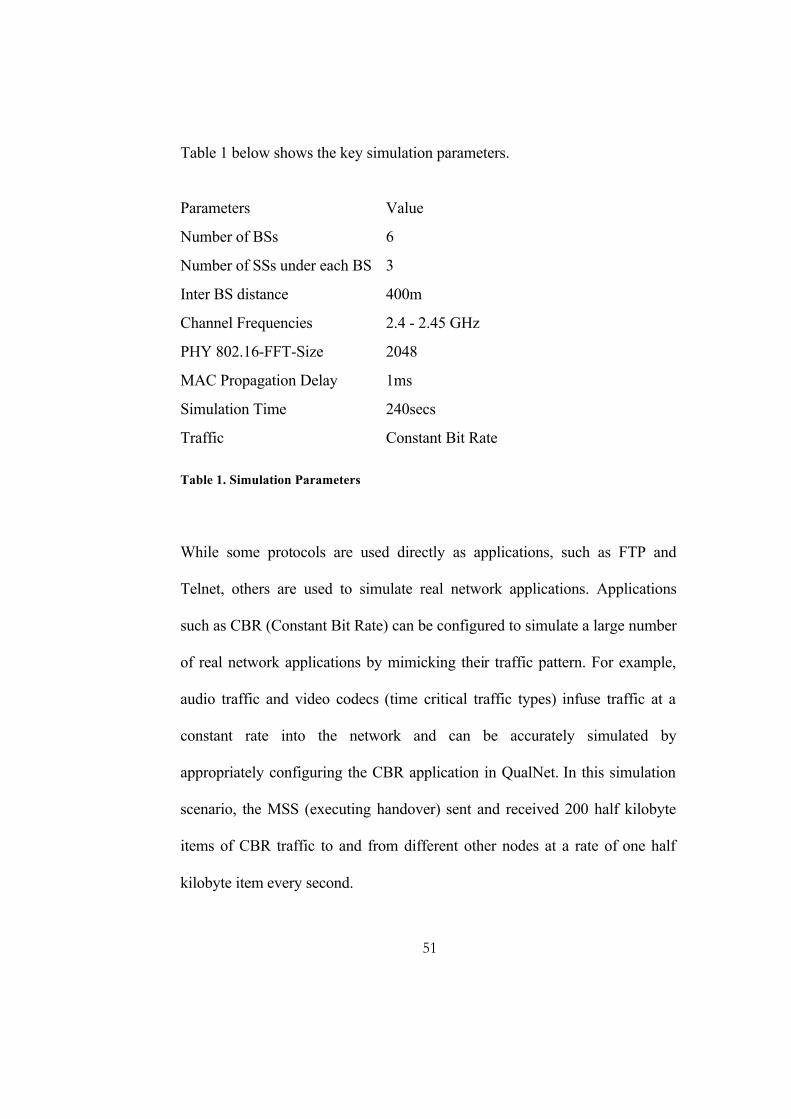
Table 1 below shows the key simulation parameters.
Parameters Value
Number of BSs 6
Number of SSs under each BS 3
Inter BS distance 400m
Channel Frequencies 2.4 - 2.45 GHz
PHY 802.16-FFT-Size 2048
MAC Propagation Delay 1ms
Simulation Time 240secs
Traffic Constant Bit Rate Table 1. Simulation Parameters
While some protocols are used directly as applications, such as FTP and
Telnet, others are used to simulate real network applications. Applications
such as CBR (Constant Bit Rate) can be configured to simulate a large number
of real network applications by mimicking their traffic pattern. For example,
audio traffic and video codecs (time critical traffic types) infuse traffic at a
constant rate into the network and can be accurately simulated by
appropriately configuring the CBR application in QualNet. In this simulation
scenario, the MSS (executing handover) sent and received 200 half kilobyte
items of CBR traffic to and from different other nodes at a rate of one half
kilobyte item every second.
52
The figures of various stages have been tabulated in Table 2 in seconds.
Network Topology Acquisition Phase Handover Phase
MOB_SCN_REQ
MOB_SCN-RSP
MOB_SCN-REP
MOB_MSHO-REQ
HO_IND
Time taken
34.91743154
34.92745092
35.27761165
35.57776174
35.61778176
0.70035
58.00897154
58.01899093
58.36915167
58.58926174
58.62928175
0.62031
110.3551316
110.365151
110.7153116
111.0174617
111.0574817
0.70235
122.6412715
122.6512909
123.0014517
123.1815417
123.2215618
0.58029
149.3746315
149.3846509
149.7348117
149.9349117
149.9749318
0.6003
174.8873816
174.8974009
175.2475622
175.2575813
175.2875823
0.400201
Table 2. Total time taken for NTAP and handover (seconds)
4.2.5.2 Analysis
Analytical results of typical 802.16e are not available at the time of this
research work. Hence a comparison of the simulated results with typical values
is not possible at the time of writing this thesis.
Analyzing the simulation results (and presuming that it is comparative to
typical values of 802.16e), it is observed that the process before actual