1077-2626 (c) 2015 IEEE. Personal use is permitted, but republication/redistribution requires IEEE permission. See http://www.ieee.org/publications_standards/publications/rights/index.html for more information. This article has been accepted for publication in a future issue of this journal, but has not been fully edited. Content may change prior to final publication. Citation information: DOI 10.1109/TVCG.2015.2459902, IEEE Transactions on Visualization and Computer Graphics MobileFusion: Real-time Volumetric Surface Reconstruction and Dense Tracking On Mobile Phones Peter Ondr´ uˇ ska, Pushmeet Kohli and Shahram Izadi Fig. 1. Example objects scanned in real-time on a mobile phone using our system. Note we only use the internal RGB camera, and all computation is performed on the device. Abstract—We present the first pipeline for real-time volumetric surface reconstruction and dense 6DoF camera tracking running purely on standard, off-the-shelf mobile phones. Using only the embedded RGB camera, our system allows users to scan objects of varying shape, size, and appearance in seconds, with real-time feedback during the capture process. Unlike existing state of the art methods, which produce only point-based 3D models on the phone, or require cloud-based processing, our hybrid GPU/CPU pipeline is unique in that it creates a connected 3D surface model directly on the device at 25Hz. In each frame, we perform dense 6DoF tracking, which continuously registers the RGB input to the incrementally built 3D model, minimizing a noise aware photoconsistency error metric. This is followed by efficient key-frame selection, and dense per-frame stereo matching. These depth maps are fused volumetrically using a method akin to KinectFusion, producing compelling surface models. For each frame, the implicit surface is extracted for live user feedback and pose estimation. We demonstrate scans of a variety of objects, and compare to a Kinect-based baseline, showing on average ∼ 1.5cm error. We qualitatively compare to a state of the art point-based mobile phone method, demonstrating an order of magnitude faster scanning times, and fully connected surface models. Index Terms—3D object scanning, surface reconstruction, mobile computing 1 I NTRODUCTION In recent years, low-cost object scanning has become a key consumer scenario, spurred on by interest around 3D printing, and more ubiq- uitous ways to consume and share 3D models on our devices (e.g. WebGL). The importance of providing live feedback during the acqui- sition process is particularly important, and ensures that the object or scene is captured without missing important details or parts. Systems such as KinectFusion [16, 9] have demonstrated the importance of live capture of 3D surface models as opposed to point-based representa- tions (e.g. [25]). Surfaces encode connectivity information, allowing • Peter Ondr ´ uˇ ska is a DPhil student at Mobile Robotics Group, University of Oxford. E-mail: [email protected]. • Pushmeet Kohli is at Microsoft Research. E-mail: [email protected]. • Shahram Izadi is at Microsoft Research. E-mail: [email protected]. real-world geometry to be modeled in a spatially continuous manner. These connected surface models also seamlessly integrate into existing 3D applications and tools e.g. for viewing and editing 3D content, printing or game physics. However, the majority of existing methods for live 3D surface reconstruction require active depth sensors and/or high end GPUs. This limits object scanning scenarios to PCs or high end laptops and tablets, with custom hardware. Whilst work, such as Google’s Tango project [8] have begun to explore more integrated solutions for mobile depth camera hardware, the cost, form-factor, and power considerations have yet to make such devices ubiquitous. We present a new system for making real-time scanning of 3D sur- face models even more cheaper and ubiquitous, using mobile phones we already have in our pockets, without any hardware modification. Ex- isting state of the art mobile methods approximate surfaces using simple visual hull constraints [23], Delaunay triangulation [18], or purely point- based representations [28, 12]; or use cloud-based processing to avoid on-device computation [2]. Instead our system reconstructs real-time 3D surface models directly on the device, allowing lightweight capture of detailed 3D objects, at speeds that have yet to be demonstrated by other systems. We describe our pipeline in full, emphasizing compo-
Transcript
1077-2626 (c) 2015 IEEE. Personal use is permitted, but republication/redistribution requires IEEE permission. Seehttp://www.ieee.org/publications_standards/publications/rights/index.html for more information.
This article has been accepted for publication in a future issue of this journal, but has not been fully edited. Content may change prior to final publication. Citation information: DOI10.1109/TVCG.2015.2459902, IEEE Transactions on Visualization and Computer Graphics
MobileFusion: Real-time Volumetric Surface Reconstruction andDense Tracking On Mobile Phones
Peter Ondruska, Pushmeet Kohli and Shahram Izadi
Fig. 1. Example objects scanned in real-time on a mobile phone using our system. Note we only use the internal RGB camera, and allcomputation is performed on the device.
Abstract—We present the first pipeline for real-time volumetric surface reconstruction and dense 6DoF camera tracking running purelyon standard, off-the-shelf mobile phones. Using only the embedded RGB camera, our system allows users to scan objects of varyingshape, size, and appearance in seconds, with real-time feedback during the capture process. Unlike existing state of the art methods,which produce only point-based 3D models on the phone, or require cloud-based processing, our hybrid GPU/CPU pipeline is uniquein that it creates a connected 3D surface model directly on the device at 25Hz. In each frame, we perform dense 6DoF tracking, whichcontinuously registers the RGB input to the incrementally built 3D model, minimizing a noise aware photoconsistency error metric. Thisis followed by efficient key-frame selection, and dense per-frame stereo matching. These depth maps are fused volumetrically usinga method akin to KinectFusion, producing compelling surface models. For each frame, the implicit surface is extracted for live userfeedback and pose estimation. We demonstrate scans of a variety of objects, and compare to a Kinect-based baseline, showing onaverage ∼ 1.5cm error. We qualitatively compare to a state of the art point-based mobile phone method, demonstrating an order ofmagnitude faster scanning times, and fully connected surface models.
Index Terms—3D object scanning, surface reconstruction, mobile computing
1 INTRODUCTION
In recent years, low-cost object scanning has become a key consumerscenario, spurred on by interest around 3D printing, and more ubiq-uitous ways to consume and share 3D models on our devices (e.g.WebGL). The importance of providing live feedback during the acqui-sition process is particularly important, and ensures that the object orscene is captured without missing important details or parts. Systemssuch as KinectFusion [16, 9] have demonstrated the importance of livecapture of 3D surface models as opposed to point-based representa-tions (e.g. [25]). Surfaces encode connectivity information, allowing
• Peter Ondruska is a DPhil student at Mobile Robotics Group, University ofOxford. E-mail: [email protected].
• Pushmeet Kohli is at Microsoft Research. E-mail: [email protected].• Shahram Izadi is at Microsoft Research. E-mail: [email protected].
real-world geometry to be modeled in a spatially continuous manner.These connected surface models also seamlessly integrate into existing3D applications and tools e.g. for viewing and editing 3D content,printing or game physics. However, the majority of existing methodsfor live 3D surface reconstruction require active depth sensors and/orhigh end GPUs. This limits object scanning scenarios to PCs or highend laptops and tablets, with custom hardware. Whilst work, suchas Google’s Tango project [8] have begun to explore more integratedsolutions for mobile depth camera hardware, the cost, form-factor, andpower considerations have yet to make such devices ubiquitous.
We present a new system for making real-time scanning of 3D sur-face models even more cheaper and ubiquitous, using mobile phoneswe already have in our pockets, without any hardware modification. Ex-isting state of the art mobile methods approximate surfaces using simplevisual hull constraints [23], Delaunay triangulation [18], or purely point-based representations [28, 12]; or use cloud-based processing to avoidon-device computation [2]. Instead our system reconstructs real-time3D surface models directly on the device, allowing lightweight captureof detailed 3D objects, at speeds that have yet to be demonstrated byother systems. We describe our pipeline in full, emphasizing compo-
1077-2626 (c) 2015 IEEE. Personal use is permitted, but republication/redistribution requires IEEE permission. Seehttp://www.ieee.org/publications_standards/publications/rights/index.html for more information.
This article has been accepted for publication in a future issue of this journal, but has not been fully edited. Content may change prior to final publication. Citation information: DOI10.1109/TVCG.2015.2459902, IEEE Transactions on Visualization and Computer Graphics
nents for uncertainty-aware dense model tracking, robust key-frameselection, dense stereo, volumetric fusion and surface extraction, andtheir efficient mobile phone implementation, which allows for 25Hzperformance. We show qualitative results of our system (see Figure 1and accompanying video 1), and compare to the point-based methodof [28, 12]. Additionally, we compare the accuracy of our methodquantitatively against a consumer depth camera baseline using a newdataset of 3D reconstructions which we make public.
Our key contributions can be summarized as:
• The first real-time fully dense surface reconstruction pipelinefor mobile phones, which operates only on live RGB input, withcomputation fully on the device. This includes at 25 frames-per-second: dense camera tracking, key frame selection, dense stereomatching, volumetric depth map fusion, and raycast-based surfaceextraction.
• A dense, feature-free, six degree-of-freedom (6DoF) tracker, reg-istering the RGB data to the volumetric surface model in real-time.Whilst semi-dense methods for mobile phone hardware exist [26],to our knowledge, this is the first time that a fully dense methodhas been demonstrated. We extend [17] modeling uncertaintydirectly from the implicit volumetric surface, and fast GPU-basedmodel extraction and alignment.
• Demonstration of volumetric depth map fusion [4, 16, 9] on com-modity mobile phones. Including extensions to [21] for morerobust key-frame selection, and [16, 9] for more efficient depthmap fusion and extraction.
• Compelling new object scanning examples, demonstrating ex-tracted 3D meshes at speeds and quality yet to obtained withoff-the-shelf mobile phone hardware.
• A new dataset of 3D models that enables quantitative evaluationof methods for dense surface reconstruction. 2
2 RELATED WORK
In terms of active sensors, early 3D scanning systems used customstructured light sensors and point-based techniques for 3D object acqui-sition [25, 30]. The advent of consumer depth cameras such as Kinect,and GPGPU computation capabilities gave rise to real-time surfacereconstruction systems such as KinectFusion [16, 9], based on moresophisticated volumetric depth map fusion techniques [4]. Whilst excit-ing work exists on mobile depth cameras [8, 24], few mobile phoneshave such capabilities today. The RGB camera remains the prevalentand ubiquitous visual sensor, and due to costs, power, form-factor andphoto capture scenarios, this is likely to remain the case in the nearfuture.
The ubiquity of visible light cameras has motivated much researchin real-time or live structure from motion (SfM), multi-view stereo(MVS) or simultaneous localization and mapping (SLAM). Early workdemonstrated real-time disparity estimation using handheld cameras[20], as well as live [19] or efficient [32] GPU-based depth map fusiontechniques. This line of research even explored extending the implicitvolumetric surface reconstruction techniques proposed for active sen-sors [4].
Early SLAM systems [11, 5] instead looked at sparse mappingusing single monocular cameras, for the purpose of real-time 6DoFtracking. More recently, there has been a shift towards semi-dense[6, 7] or fully dense [14] tracking techniques but again the purpose hasremained robust camera tracking rather than detailed 3D reconstructionper say. Dense stereo matching techniques have been combined witheither sparse [21, 15, 27] or dense trackers [14] to create compellingsurface reconstructions. In this later work [21, 14] per frame, densestereo computation was combined with volumetric techniques [4, 16, 9].
1Video is available at: http://youtu.be/5tsLLq02xnk2 Datasets are available at: http://mrg.robots.ox.ac.uk/mrg_
people/peter-ondruska/
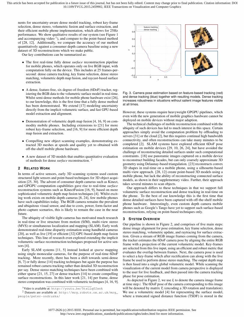
−0.5 0 0.5 1−0.4
−0.2
0
0.2
0.4
0.6
0.8
1
x
z
feature tracking
dense tracking
Fig. 3. Camera pose estimation based on feature-based tracking (red)and dense tracking (blue) together with resulting models. Dense trackingincreases robustness in situations without salient image features visibleat all times.
However, these systems require heavyweight GPGPU pipelines, whicheven with the new generation of mobile graphics hardware cannot bedeployed on mobile devices without major adaption.
The technical challenges of mobile reconstruction combined with theubiquity of such devices has led to much interest in this space. Certainapproaches simply avoid the computation problem by offloading toservers [31] or the cloud [2], but this requires continual high bandwidthconnectivity, and often reconstructions can take many minutes to becompleted [2]. SLAM systems have explored efficient 6DoF poseestimation on mobile devices [29, 10, 26, 24], but have avoided thechallenge of reconstructing detailed surfaces under such computationalconstraints. [18] use panoramic images captured on a mobile deviceto reconstruct building facades, but can only coarsely approximate 3Dgeometry using Delaunay-based triangulation. [23] reconstructs convex3D shapes in real-time on a mobile phone, using a silhouette-basedmulti-view approach. [28, 12] create point-based 3D models using amobile phone, but lack the ability of reconstructing connected surfacemodels, as shown in their supplementary video. Further, their approachtakes several minutes to scan objects.
Our approach differs to these techniques in that we support fullvolumetric surface reconstruction and dense tracking in real-time onthe phone. To the best of our knowledge this is the first time thatdense detailed surfaces have been captured with off-the-shelf mobilephone hardware. Interestingly, even custom depth camera mobilephones such as Google’s Tango have yet to support such surface-basedreconstructions, relying on point-based techniques only.
3 SYSTEM OVERVIEW
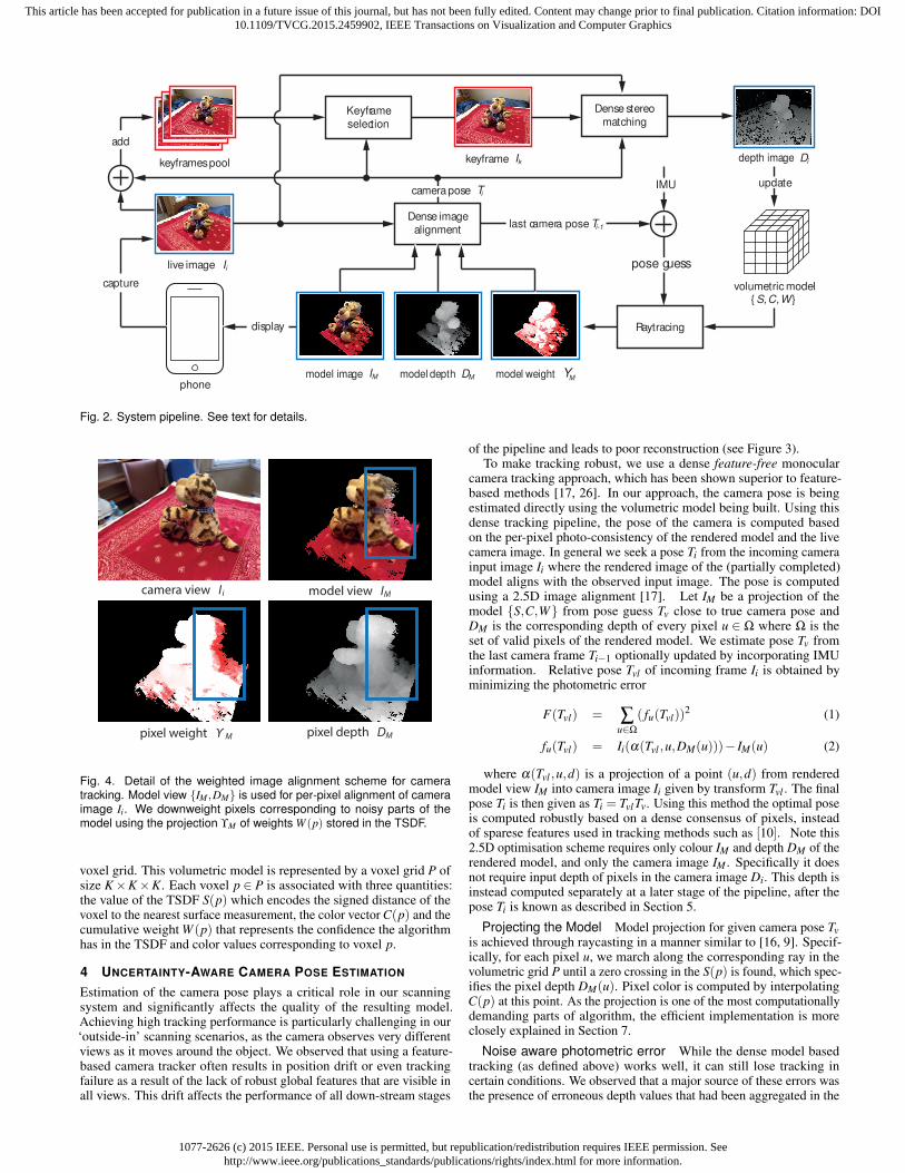
Our pipeline is shown in Figure 2, and comprises of five main steps:dense image alignment for pose estimation, key frame selection, densestereo matching, volumetric update, and raytracing for surface extrac-tion. Given a stream of RGB image frames coming from the camera,the tracker estimates the 6DoF camera pose by aligning the entire RGBframe with a projection of the current volumetric model. Key-framesare selected from this live input, using an efficient and robust metric thatevaluates the overlap between frames. Next, the camera pose is usedto select a key-frame which after rectification can along with the liveframe be used to perform dense stereo matching. The output depth mapis then fused into a single global volumetric model. While scanning thevisualization of the current model from camera perspective is displayedto the user for live feedback, and then passed into the camera trackingphase for pose estimation.
As depicted in Figure 2, we use Ii to denote the camera image frameat time step i. The 6DoF pose of the camera corresponding to this imagewill be denoted by matrix Ti (encoding a 3D rotation and translation).We use a volumetric model [4] for representing the surface model,where a truncated signed distance function (TSDF) is stored in the
1077-2626 (c) 2015 IEEE. Personal use is permitted, but republication/redistribution requires IEEE permission. Seehttp://www.ieee.org/publications_standards/publications/rights/index.html for more information.
This article has been accepted for publication in a future issue of this journal, but has not been fully edited. Content may change prior to final publication. Citation information: DOI10.1109/TVCG.2015.2459902, IEEE Transactions on Visualization and Computer Graphics
volumetric model
Dense image
alignment
Keyframe
selection
phone
live image
keyframes pool
add
model depth
display
capture
Dense stereo
matching
Raytracing
IMU
keyframe
model image model weight
camera pose
pose guess
last camera pose
depth image
IM DM M
Ii
Ik Di
updateTi
Ti-1
Y
S , C , W
Fig. 2. System pipeline. See text for details.
model view I
pixel weight Υ
M
M pixel depth DM
camera view Ii
Fig. 4. Detail of the weighted image alignment scheme for cameratracking. Model view IM ,DM is used for per-pixel alignment of cameraimage Ii. We downweight pixels corresponding to noisy parts of themodel using the projection ϒM of weights W (p) stored in the TSDF.
voxel grid. This volumetric model is represented by a voxel grid P ofsize K×K×K. Each voxel p ∈ P is associated with three quantities:the value of the TSDF S(p) which encodes the signed distance of thevoxel to the nearest surface measurement, the color vector C(p) and thecumulative weight W (p) that represents the confidence the algorithmhas in the TSDF and color values corresponding to voxel p.
4 UNCERTAINTY-AWARE CAMERA POSE ESTIMATION
Estimation of the camera pose plays a critical role in our scanningsystem and significantly affects the quality of the resulting model.Achieving high tracking performance is particularly challenging in our‘outside-in’ scanning scenarios, as the camera observes very differentviews as it moves around the object. We observed that using a feature-based camera tracker often results in position drift or even trackingfailure as a result of the lack of robust global features that are visible inall views. This drift affects the performance of all down-stream stages
of the pipeline and leads to poor reconstruction (see Figure 3).To make tracking robust, we use a dense feature-free monocular
camera tracking approach, which has been shown superior to feature-based methods [17, 26]. In our approach, the camera pose is beingestimated directly using the volumetric model being built. Using thisdense tracking pipeline, the pose of the camera is computed basedon the per-pixel photo-consistency of the rendered model and the livecamera image. In general we seek a pose Ti from the incoming camerainput image Ii where the rendered image of the (partially completed)model aligns with the observed input image. The pose is computedusing a 2.5D image alignment [17]. Let IM be a projection of themodel S,C,W from pose guess Tv close to true camera pose andDM is the corresponding depth of every pixel u ∈ Ω where Ω is theset of valid pixels of the rendered model. We estimate pose Tv fromthe last camera frame Ti−1 optionally updated by incorporating IMUinformation. Relative pose Tvl of incoming frame Ii is obtained byminimizing the photometric error
F(Tvl) = ∑u∈Ω
( fu(Tvl))2 (1)
fu(Tvl) = Ii(α(Tvl ,u,DM(u)))− IM(u) (2)
where α(Tvl ,u,d) is a projection of a point (u,d) from renderedmodel view IM into camera image Ii given by transform Tvl . The finalpose Ti is then given as Ti = TvlTv. Using this method the optimal poseis computed robustly based on a dense consensus of pixels, insteadof sparese features used in tracking methods such as [10]. Note this2.5D optimisation scheme requires only colour IM and depth DM of therendered model, and only the camera image IM . Specifically it doesnot require input depth of pixels in the camera image Di. This depth isinstead computed separately at a later stage of the pipeline, after thepose Ti is known as described in Section 5.
Projecting the Model Model projection for given camera pose Tvis achieved through raycasting in a manner similar to [16, 9]. Specif-ically, for each pixel u, we march along the corresponding ray in thevolumetric grid P until a zero crossing in the S(p) is found, which spec-ifies the pixel depth DM(u). Pixel color is computed by interpolatingC(p) at this point. As the projection is one of the most computationallydemanding parts of algorithm, the efficient implementation is moreclosely explained in Section 7.
Noise aware photometric error While the dense model basedtracking (as defined above) works well, it can still lose tracking incertain conditions. We observed that a major source of these errors wasthe presence of erroneous depth values that had been aggregated in the
1077-2626 (c) 2015 IEEE. Personal use is permitted, but republication/redistribution requires IEEE permission. Seehttp://www.ieee.org/publications_standards/publications/rights/index.html for more information.
This article has been accepted for publication in a future issue of this journal, but has not been fully edited. Content may change prior to final publication. Citation information: DOI10.1109/TVCG.2015.2459902, IEEE Transactions on Visualization and Computer Graphics
Fig. 5. Progress of object scanning from a sequence of length 25 seconds. Each column captures live camera view, per frame depth map, raytracedRGB, 3D model and model confidence, over time.
volumetric TSDF (see Figure 4) resulting in outliers in the cost functionEquation 1. This is especially the case when occluded parts of the objectare seen for the first time. Due to limited number of observations ofthese parts of the object, the volumetric data is noisy. This problem canbe solved using a robust cost function based on the Huber norm. Usingthe Huber norm however makes the optimisation more complicated asit involves iterative re-weighting Levenberg-Marquardt minimization[26]. Instead we used a simpler method which explicitly down-weightscontribution of pixels in IM originating from recently initialised voxelsi.e. having small voxel weight W (p). Specifically we assign a weightto each pixel u such that the optimized photometric error becomes
F(Tvl) = ∑u∈Ω
ϒM(u)( fu(Tvl))2. (3)
Weights ϒM for each pixel u are computed simply by projecting voxelweight function W (p) which in turn is computed using the number andvalue of observations that have been made for each voxel. Minimizationof the uncertainty aware photometric error defined above is achievedthrough simple Gauss-Newton gradient descent [3, 6, 17]. In practicethis optimization scheme works well for smooth camera trajectoriesand video frame rates (25Hz). It does not even require a coarse-to-fine pyramidal approach [26, 27]. For rapid motion, a more efficientpyramidal approach together with a more robust cost function can beused to further improve tracking performance.
Figure 6, shows progress of minimizing the cost function in Equa-tion 3. In this plot we see the importance of frame-rate for fast conver-gence of our optimizer. In our system we maintain 25Hz for the fullpipeline, which given the smaller distances traveled per frame results inconvergence after around 3 frames. As shown, if our system was slowerthen the number of solver iterations would be significantly higher.
5 MONOCULAR DEPTH ESTIMATION
After pose estimation, we estimate depth Di of the input image using asimple pair-wise stereo matching method. Using the current camera im-age and one selected key-frame from the past, this method traingulatesthe depth of every pixel using a block-matching schema to find densepixel correspondances between both frames. We chose this methodas opposed to methods using multiple-frame stereo [27] as it allowsfaster incremental build-up of the model, and in practice, the level ofredundancy of per-frame estimation allows filtering of depth outliers
5 10 15 20 25 30 35
200
400
600
800
1000
1200
1400
1600
1800
iteration
photo
metr
ic e
rror
F(T
)
FPS=25
FPS=12
FPS=6
FPS=4
Fig. 6. Iterative alignment of live image during camera tracking. Our plotsshow the importance of maintaining high frame-rate camera tracking toensure fast and precise convergence.
caused by occlusions or lack of texture. Moreover as further describedin Section 7. the block-matching can be implemented extremely effi-ciently on a mobile phone GPU. This allows for a fast depth-estimationsystem that runs at 25Hz as opposed to 0.5Hz of [28, 12] coarse-to-finescheme.
Key-frame Selection We maintain a pool of last M = 40 RGBframes and choose appropriate key-frame Ik for stereo matching, basedon very simple but robust scoring function which can be computedextremely efficiently given just knowledge of camera poses. Uponreceiving a new input frame, we look at this pool to select a key-frame.We need to trade-off between two objectives during key-frame selection.Firstly, to ensure that depth can be computed for as many pixels aspossible in the image, we want to ensure that there is a high-overlapbetween the frame and the current camera view. In other words, thekey-frame captures the same part of the scene as the current cameraview. This objective can be quantified in terms of the fraction of overlapS∩(Tk) between the rectified camera image and considered key-frame.
Secondly, we need to make sure that the stereo pair containing thekey-frame has an appropriate baseline. Having a very small baselinewould mean that depth for objects that are farther away cannot be
1077-2626 (c) 2015 IEEE. Personal use is permitted, but republication/redistribution requires IEEE permission. Seehttp://www.ieee.org/publications_standards/publications/rights/index.html for more information.
This article has been accepted for publication in a future issue of this journal, but has not been fully edited. Content may change prior to final publication. Citation information: DOI10.1109/TVCG.2015.2459902, IEEE Transactions on Visualization and Computer Graphics
computed. Here, there is a trade-off between the width of the baseline,accuracy and maximum disparity search range, where the depth ofobjects less than 1/dmax cannot be estimated. As the scanned object isinside the voxel grid, projecting the 8 vertices of the voxel cube provideupper δmax(Tk) and lower bound δmin(Tk) for the object disparity. Topenalize either disparity of pixels being over the designated range orutilizing only a small fraction of it, we consider the term Sd(Tk) =
−∣∣∣1− δmax(Tk)
dmax
∣∣∣ and the final scoring function is simply a sum of thesetwo terms:
S(Tk) = S∩(Tk)+Sd(Tk) (4)
Disparity Estimation The depth map for each frame of the imagestream can be computed through dense stereo matching between therectified pair of current camera view (Ii,Ti) and past key-frame (Ik, Tk)in a manner similar to [21]. An interesting trade-off is working witha simpler and faster, but less accurate, stereo method, as a opposed toone that is more precise but less efficient. In practice, given other partsof the pipeline (in particular camera tracking) rely on maintaining highframerates, and given our ability to fuse every frame volumetrically.We found that going for efficiency and less per frame accuracy, but withhigh amount of redundancy in terms of computed and fused depthsmaps leads to compelling 3D reconstructions.
However, as highlighted, it is critical to maintain framerate forrobust tracking (and hence reconstruction), therefore instead of usinga propagation-based stereo method, mobile device reduces a numberof computational constraints. These considerations prevented us fromusing sophisticated but slow algorithms for stereo matching as theylead to drastic reductions in the frame rate and result in poor trackingand 3D reconstruction.
This trade-off led us to a simple but fast, block matching approach fordisparity estimation. As further discussed in Section 7, we implementedthe block matching method to run on the mobile phone GPU whichallowed us to perform stereo matching in real-time. We performedblock matching over dmax = 64 steps along the epipolar line with patchsize of 5x5 pixels, and sum of square error matching score. We alsoexperimented with larger patch sizes which resulted in smoother butless detailed depth maps. We do L-R check to remove outliers causedby occlusions or lack of texture. Furthermore we obtained subpixelaccuracy by post-processing the depth maps using parabola fitting inthe neighbourhood of the disparity with minimum cost. Implementationof these operation on the GPU allowed us to generate depth maps of320x240 resolution at 25Hz.
Note we do not provide any further post-processing refinementof depth-maps such as total-variation optimisation [27] or spatial-regularisation [26] as our aim is not to generate high-quality individualdepth maps but rather fuse many moderate-quality depth maps withregularisation inherently implemented in the volumetric fusion step.
6 FUSING DEPTH IMAGES
For every generated depth map Dk, we fuse the observations to refineour volumetric model. This step is akin to the voxel update performedin [16], but as described later, can be performed for all voxels inde-pendently without requiring an explicit sweep of the volume. Usingvolumetric fusion has numerous advantages including robust handlingof outliers and efficient model update. Moreover as opposed to unstruc-tured point cloud or surfel model representations used in recent mobileapproaches [12, 28], this volumetric approach provides a continuousand connected implicit surface model, which can be extracted usingraycasting or marching cubes [13].
For any voxel p ∈ P, given it’s projection into camera space q = Ti p,and the projection into camera view π(q) = ( fx
qxqz+ cx, fy
qyqz+ cy), we
compute the quantities:
si(p) = Di(π(q))−qz (5)ci(p) = Ii(π(q)) (6)
K=128, FPS=25Hz K=256, FPS=15Hz
K=64, FPS=10Hz K=128, FPS=4Hz
Fig. 7. Effect of different model resolution and FPS on model quality. Ourcurrent implementation supports K = 128 at 25Hz and K = 256 at 15Hz.Note that processing speed is however the more dominant contributor tomodel quality. This is because at higher frame-rates, the redundancy ofdepth maps fused volumetrically leads to greater denoised results evenat lower resolutions.
and use them to perform a weighted update of the model as
Si(p) =Si−1(p) ·Wi−1(p)+ si(p) ·wi(p)
Wi−1(p)+wi(p)(7)
Ci(p) =Ci−1(p) ·Wi−1(p)+ ci(p) ·wi(p)
Wi−1(p)+wi(p)(8)
Wi(p) = Wi−1(p)+wi(p) (9)
where wk(p) is the weight of the new measurement. Note we onlyupdate voxels which project inside the camera image and for whichthe pixel depth information is valid (i.e. was not rejected by the L-Rcheck of stereo depth computation step as an outlier). Filtering outdepth measurements outliers greatly reduces the amount of noise inthe depth fusion step. For this reason we have used a constant weightwk(p) = 1 for new measurements and found no considerable differencewith weighted average methods. Moreover as in [16] we only updatevoxels within a range around the surface having sk(p)>−µ (i.e. visiblevoxels) and truncate the remaining sk(p) to [−µ,µ] (where µ = 8voxels). Similarly, we limit the maximum weight Wk(p) to Wmax = 50.The voxel resolution and frame-rate are again an important trade-offfor reconstruction quality, as shown in Figure 7.
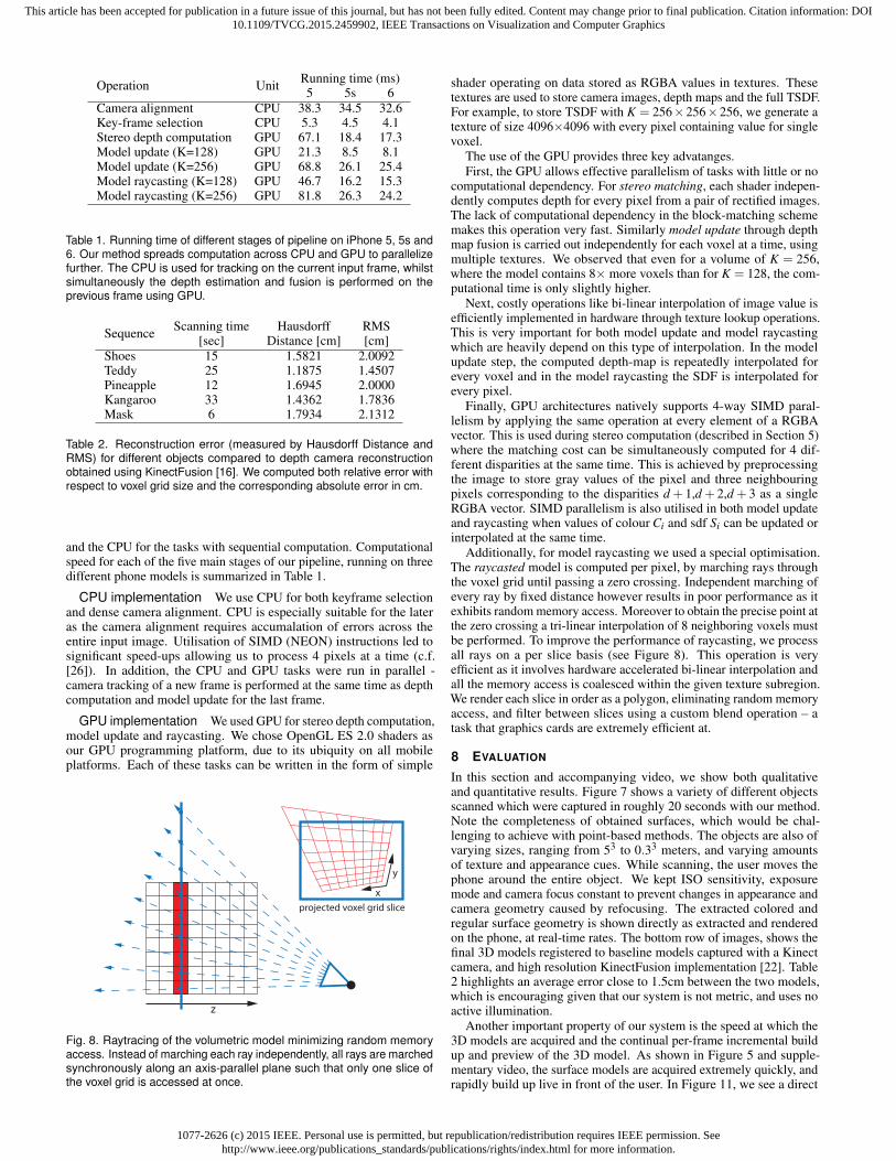
7 MOBILE PHONE IMPLEMENTATION
In this section we describe some of the important factors which al-lowed a real-time implementation of the described pipeline on an AppleiPhone 6. Our implementation utilizes both CPU and GPU of the mo-bile phone to process the camera stream at a resolution of 320x240 at25Hz for both tracking and reconstruction.
Initialization To bootstrap the system we use a publicly availablefeature-based tracker [1], although open source trackers such as [10] or[26] can be used instead. Running this tracker, the user first interactivelyspecifies the position of the volumetric grid (see accompanying video),such that the desired object is placed within. The tracker is used toprovide pose Ti to initialize the model and dense tracking pipelines.
Mobile CPU & GPU Utilization Despite significant developmentof mobile devices in recent years, they are still 5-20x less powerfulcompared to their desktop counterparts. We measured the raw peakCPU performance of our platform to be 3GFlops using SIMD instruc-tions and 70GFlops on GPU using OpenGL ES 2.0 shaders. Wherepossible we chose to use the GPU for demanding parallelizable tasks
1077-2626 (c) 2015 IEEE. Personal use is permitted, but republication/redistribution requires IEEE permission. Seehttp://www.ieee.org/publications_standards/publications/rights/index.html for more information.
This article has been accepted for publication in a future issue of this journal, but has not been fully edited. Content may change prior to final publication. Citation information: DOI10.1109/TVCG.2015.2459902, IEEE Transactions on Visualization and Computer Graphics
Table 1. Running time of different stages of pipeline on iPhone 5, 5s and6. Our method spreads computation across CPU and GPU to parallelizefurther. The CPU is used for tracking on the current input frame, whilstsimultaneously the depth estimation and fusion is performed on theprevious frame using GPU.
Sequence Scanning time Hausdorff RMS[sec] Distance [cm] [cm]
Table 2. Reconstruction error (measured by Hausdorff Distance andRMS) for different objects compared to depth camera reconstructionobtained using KinectFusion [16]. We computed both relative error withrespect to voxel grid size and the corresponding absolute error in cm.
and the CPU for the tasks with sequential computation. Computationalspeed for each of the five main stages of our pipeline, running on threedifferent phone models is summarized in Table 1.
CPU implementation We use CPU for both keyframe selectionand dense camera alignment. CPU is especially suitable for the lateras the camera alignment requires accumalation of errors across theentire input image. Utilisation of SIMD (NEON) instructions led tosignificant speed-ups allowing us to process 4 pixels at a time (c.f.[26]). In addition, the CPU and GPU tasks were run in parallel -camera tracking of a new frame is performed at the same time as depthcomputation and model update for the last frame.
GPU implementation We used GPU for stereo depth computation,model update and raycasting. We chose OpenGL ES 2.0 shaders asour GPU programming platform, due to its ubiquity on all mobileplatforms. Each of these tasks can be written in the form of simple
z
x
y
projected voxel grid slice
Fig. 8. Raytracing of the volumetric model minimizing random memoryaccess. Instead of marching each ray independently, all rays are marchedsynchronously along an axis-parallel plane such that only one slice ofthe voxel grid is accessed at once.
shader operating on data stored as RGBA values in textures. Thesetextures are used to store camera images, depth maps and the full TSDF.For example, to store TSDF with K = 256×256×256, we generate atexture of size 4096×4096 with every pixel containing value for singlevoxel.
The use of the GPU provides three key advatanges.First, the GPU allows effective parallelism of tasks with little or no
computational dependency. For stereo matching, each shader indepen-dently computes depth for every pixel from a pair of rectified images.The lack of computational dependency in the block-matching schememakes this operation very fast. Similarly model update through depthmap fusion is carried out independently for each voxel at a time, usingmultiple textures. We observed that even for a volume of K = 256,where the model contains 8× more voxels than for K = 128, the com-putational time is only slightly higher.
Next, costly operations like bi-linear interpolation of image value isefficiently implemented in hardware through texture lookup operations.This is very important for both model update and model raycastingwhich are heavily depend on this type of interpolation. In the modelupdate step, the computed depth-map is repeatedly interpolated forevery voxel and in the model raycasting the SDF is interpolated forevery pixel.
Finally, GPU architectures natively supports 4-way SIMD paral-lelism by applying the same operation at every element of a RGBAvector. This is used during stereo computation (described in Section 5)where the matching cost can be simultaneously computed for 4 dif-ferent disparities at the same time. This is achieved by preprocessingthe image to store gray values of the pixel and three neighbouringpixels corresponding to the disparities d + 1,d + 2,d + 3 as a singleRGBA vector. SIMD parallelism is also utilised in both model updateand raycasting when values of colour Ci and sdf Si can be updated orinterpolated at the same time.
Additionally, for model raycasting we used a special optimisation.The raycasted model is computed per pixel, by marching rays throughthe voxel grid until passing a zero crossing. Independent marching ofevery ray by fixed distance however results in poor performance as itexhibits random memory access. Moreover to obtain the precise point atthe zero crossing a tri-linear interpolation of 8 neighboring voxels mustbe performed. To improve the performance of raycasting, we processall rays on a per slice basis (see Figure 8). This operation is veryefficient as it involves hardware accelerated bi-linear interpolation andall the memory access is coalesced within the given texture subregion.We render each slice in order as a polygon, eliminating random memoryaccess, and filter between slices using a custom blend operation – atask that graphics cards are extremely efficient at.
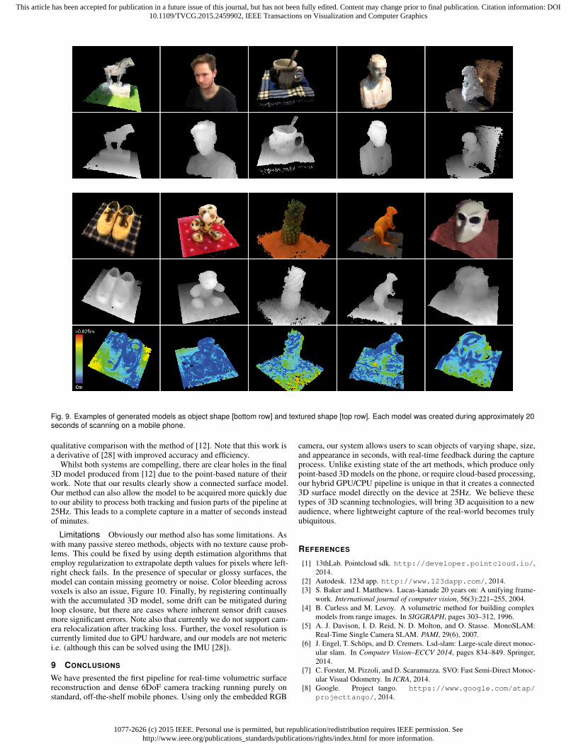
8 EVALUATION
In this section and accompanying video, we show both qualitativeand quantitative results. Figure 7 shows a variety of different objectsscanned which were captured in roughly 20 seconds with our method.Note the completeness of obtained surfaces, which would be chal-lenging to achieve with point-based methods. The objects are also ofvarying sizes, ranging from 53 to 0.33 meters, and varying amountsof texture and appearance cues. While scanning, the user moves thephone around the entire object. We kept ISO sensitivity, exposuremode and camera focus constant to prevent changes in appearance andcamera geometry caused by refocusing. The extracted colored andregular surface geometry is shown directly as extracted and renderedon the phone, at real-time rates. The bottom row of images, shows thefinal 3D models registered to baseline models captured with a Kinectcamera, and high resolution KinectFusion implementation [22]. Table2 highlights an average error close to 1.5cm between the two models,which is encouraging given that our system is not metric, and uses noactive illumination.
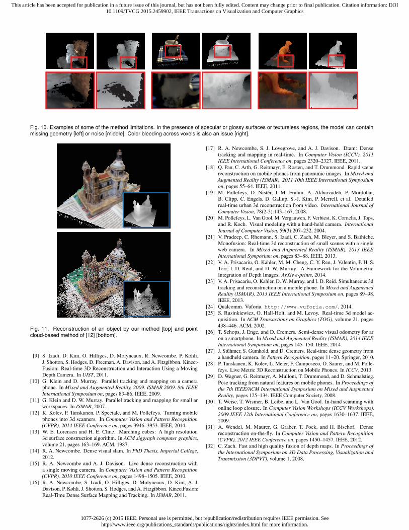
Another important property of our system is the speed at which the3D models are acquired and the continual per-frame incremental buildup and preview of the 3D model. As shown in Figure 5 and supple-mentary video, the surface models are acquired extremely quickly, andrapidly build up live in front of the user. In Figure 11, we see a direct
1077-2626 (c) 2015 IEEE. Personal use is permitted, but republication/redistribution requires IEEE permission. Seehttp://www.ieee.org/publications_standards/publications/rights/index.html for more information.
This article has been accepted for publication in a future issue of this journal, but has not been fully edited. Content may change prior to final publication. Citation information: DOI10.1109/TVCG.2015.2459902, IEEE Transactions on Visualization and Computer Graphics
Fig. 9. Examples of generated models as object shape [bottom row] and textured shape [top row]. Each model was created during approximately 20seconds of scanning on a mobile phone.
qualitative comparison with the method of [12]. Note that this work isa derivative of [28] with improved accuracy and efficiency.
Whilst both systems are compelling, there are clear holes in the final3D model produced from [12] due to the point-based nature of theirwork. Note that our results clearly show a connected surface model.Our method can also allow the model to be acquired more quickly dueto our ability to process both tracking and fusion parts of the pipeline at25Hz. This leads to a complete capture in a matter of seconds insteadof minutes.
Limitations Obviously our method also has some limitations. Aswith many passive stereo methods, objects with no texture cause prob-lems. This could be fixed by using depth estimation algorithms thatemploy regularization to extrapolate depth values for pixels where left-right check fails. In the presence of specular or glossy surfaces, themodel can contain missing geometry or noise. Color bleeding acrossvoxels is also an issue, Figure 10. Finally, by registering continuallywith the accumulated 3D model, some drift can be mitigated duringloop closure, but there are cases where inherent sensor drift causesmore significant errors. Note also that currently we do not support cam-era relocalization after tracking loss. Further, the voxel resolution iscurrently limited due to GPU hardware, and our models are not meterici.e. (although this can be solved using the IMU [28]).
9 CONCLUSIONS
We have presented the first pipeline for real-time volumetric surfacereconstruction and dense 6DoF camera tracking running purely onstandard, off-the-shelf mobile phones. Using only the embedded RGB
camera, our system allows users to scan objects of varying shape, size,and appearance in seconds, with real-time feedback during the captureprocess. Unlike existing state of the art methods, which produce onlypoint-based 3D models on the phone, or require cloud-based processing,our hybrid GPU/CPU pipeline is unique in that it creates a connected3D surface model directly on the device at 25Hz. We believe thesetypes of 3D scanning technologies, will bring 3D acquisition to a newaudience, where lightweight capture of the real-world becomes trulyubiquitous.
1077-2626 (c) 2015 IEEE. Personal use is permitted, but republication/redistribution requires IEEE permission. Seehttp://www.ieee.org/publications_standards/publications/rights/index.html for more information.
This article has been accepted for publication in a future issue of this journal, but has not been fully edited. Content may change prior to final publication. Citation information: DOI10.1109/TVCG.2015.2459902, IEEE Transactions on Visualization and Computer Graphics
Fig. 10. Examples of some of the method limitations. In the presence of specular or glossy surfaces or textureless regions, the model can containmissing geometry [left] or noise [middle]. Color bleeding across voxels is also an issue [right].
Fig. 11. Reconstruction of an object by our method [top] and pointcloud-based method of [12] [bottom].
[9] S. Izadi, D. Kim, O. Hilliges, D. Molyneaux, R. Newcombe, P. Kohli,J. Shotton, S. Hodges, D. Freeman, A. Davison, and A. Fitzgibbon. Kinect-Fusion: Real-time 3D Reconstruction and Interaction Using a MovingDepth Camera. In UIST, 2011.
[10] G. Klein and D. Murray. Parallel tracking and mapping on a cameraphone. In Mixed and Augmented Reality, 2009. ISMAR 2009. 8th IEEEInternational Symposium on, pages 83–86. IEEE, 2009.
[11] G. Klein and D. W. Murray. Parallel tracking and mapping for small arworkspaces. In ISMAR, 2007.
[12] K. Kolev, P. Tanskanen, P. Speciale, and M. Pollefeys. Turning mobilephones into 3d scanners. In Computer Vision and Pattern Recognition(CVPR), 2014 IEEE Conference on, pages 3946–3953. IEEE, 2014.
[13] W. E. Lorensen and H. E. Cline. Marching cubes: A high resolution3d surface construction algorithm. In ACM siggraph computer graphics,volume 21, pages 163–169. ACM, 1987.
[14] R. A. Newcombe. Dense visual slam. In PhD Thesis, Imperial College,2012.
[15] R. A. Newcombe and A. J. Davison. Live dense reconstruction witha single moving camera. In Computer Vision and Pattern Recognition(CVPR), 2010 IEEE Conference on, pages 1498–1505. IEEE, 2010.
[16] R. A. Newcombe, S. Izadi, O. Hilliges, D. Molyneaux, D. Kim, A. J.Davison, P. Kohli, J. Shotton, S. Hodges, and A. Fitzgibbon. KinectFusion:Real-Time Dense Surface Mapping and Tracking. In ISMAR, 2011.
[17] R. A. Newcombe, S. J. Lovegrove, and A. J. Davison. Dtam: Densetracking and mapping in real-time. In Computer Vision (ICCV), 2011IEEE International Conference on, pages 2320–2327. IEEE, 2011.
[18] Q. Pan, C. Arth, G. Reitmayr, E. Rosten, and T. Drummond. Rapid scenereconstruction on mobile phones from panoramic images. In Mixed andAugmented Reality (ISMAR), 2011 10th IEEE International Symposiumon, pages 55–64. IEEE, 2011.
[19] M. Pollefeys, D. Nister, J.-M. Frahm, A. Akbarzadeh, P. Mordohai,B. Clipp, C. Engels, D. Gallup, S.-J. Kim, P. Merrell, et al. Detailedreal-time urban 3d reconstruction from video. International Journal ofComputer Vision, 78(2-3):143–167, 2008.
[20] M. Pollefeys, L. Van Gool, M. Vergauwen, F. Verbiest, K. Cornelis, J. Tops,and R. Koch. Visual modeling with a hand-held camera. InternationalJournal of Computer Vision, 59(3):207–232, 2004.
[21] V. Pradeep, C. Rhemann, S. Izadi, C. Zach, M. Bleyer, and S. Bathiche.Monofusion: Real-time 3d reconstruction of small scenes with a singleweb camera. In Mixed and Augmented Reality (ISMAR), 2013 IEEEInternational Symposium on, pages 83–88. IEEE, 2013.
[22] V. A. Prisacariu, O. Kahler, M. M. Cheng, C. Y. Ren, J. Valentin, P. H. S.Torr, I. D. Reid, and D. W. Murray. A Framework for the VolumetricIntegration of Depth Images. ArXiv e-prints, 2014.
[23] V. A. Prisacariu, O. Kahler, D. W. Murray, and I. D. Reid. Simultaneous 3dtracking and reconstruction on a mobile phone. In Mixed and AugmentedReality (ISMAR), 2013 IEEE International Symposium on, pages 89–98.IEEE, 2013.
[24] Qualcomm. Vuforia. http://www.vuforia.com/, 2014.[25] S. Rusinkiewicz, O. Hall-Holt, and M. Levoy. Real-time 3d model ac-
quisition. In ACM Transactions on Graphics (TOG), volume 21, pages438–446. ACM, 2002.
[26] T. Schops, J. Enge, and D. Cremers. Semi-dense visual odometry for aron a smartphone. In Mixed and Augmented Reality (ISMAR), 2014 IEEEInternational Symposium on, pages 145–150. IEEE, 2014.
[27] J. Stuhmer, S. Gumhold, and D. Cremers. Real-time dense geometry froma handheld camera. In Pattern Recognition, pages 11–20. Springer, 2010.
[28] P. Tanskanen, K. Kolev, L. Meier, F. Camposeco, O. Saurer, and M. Polle-feys. Live Metric 3D Reconstruction on Mobile Phones. In ICCV, 2013.
[29] D. Wagner, G. Reitmayr, A. Mulloni, T. Drummond, and D. Schmalstieg.Pose tracking from natural features on mobile phones. In Proceedings ofthe 7th IEEE/ACM International Symposium on Mixed and AugmentedReality, pages 125–134. IEEE Computer Society, 2008.
[30] T. Weise, T. Wismer, B. Leibe, and L. Van Gool. In-hand scanning withonline loop closure. In Computer Vision Workshops (ICCV Workshops),2009 IEEE 12th International Conference on, pages 1630–1637. IEEE,2009.
[31] A. Wendel, M. Maurer, G. Graber, T. Pock, and H. Bischof. Densereconstruction on-the-fly. In Computer Vision and Pattern Recognition(CVPR), 2012 IEEE Conference on, pages 1450–1457. IEEE, 2012.
[32] C. Zach. Fast and high quality fusion of depth maps. In Proceedings ofthe International Symposium on 3D Data Processing, Visualization andTransmission (3DPVT), volume 1, 2008.


![MobileFusion: Real-time Volumetric Surface …...as Google’s Tango project [8] have begun to explore more integrated solutions for mobile depth camera hardware, the cost, form-factor,](https://static.documents.pub/doc/80x56/5f055c867e708231d4129571/mobilefusion-real-time-volumetric-surface-as-googleas-tango-project-8-have.jpg)
![Volumetric 3D Mapping in Real-Time on a CPU · Volumetric 3D Mapping in Real-Time on a CPU ... narrow band around the observed surface. ... [8]; class Brick Voxel voxel[8][8][8];](https://static.documents.pub/doc/80x56/5b87b0e77f8b9a1a248d44a2/volumetric-3d-mapping-in-real-time-on-a-cpu-volumetric-3d-mapping-in-real-time.jpg)


![ViVo: Visibility-Aware Mobile Volumetric Video Streamingfengqian/paper/vivo_mobicom20.pdfAccording to a recent market research report [22], it is expected that the volumetric video](https://static.documents.pub/doc/80x56/6077f492893bd82ded0f67e1/vivo-visibility-aware-mobile-volumetric-video-streaming-fengqianpapervivo-according.jpg)


