Mobility relaxation and electron trapping in a donor/acceptor copolymer
Marcel Schubert,1 Eduard Preis,2 James C. Blakesley,1 Patrick Pingel,1 Ullrich Scherf,2 and Dieter Neher1
1University of Potsdam, Institute of Physics and Astronomy, Karl-Liebknecht-Str. 24-25, 14476 Potsdam, Germany2Bergische University Wuppertal, Macromolecular Chemistry, 42119 Wuppertal, Germany
(Received 6 September 2012; published 17 January 2013)
To address the nature of charge transport and the origin of severe (intrinsic) trapping in electron-transportingpolymers, transient and steady-state charge transport measurements have been conducted on the prototypedonor/acceptor copolymer poly[2,7-(9,9-dialkyl-fluorene)-alt-5,5-(4′,7′-di-2-thienyl-2′,1′,3′-benzothiadiazole)](PFTBTT). A charge-generation layer technique is used to selectively address transport of the desired chargecarrier type, to perform time-of-flight measurements on samples with <200 nm thickness, and to combinethe time-of-flight and the photocharge extraction by linearly increasing voltage (photo-CELIV) techniques toinvestigate charge carrier dynamics over a wide time range. Significant trapping of free electrons is observedin the bulk of dioctyl-substituted PFTBTT (alt-PF8TBTT), introducing a strong relaxation of the charge carriermobility with time. We used Monte-Carlo simulation to simulate the measured transient data and found that allmeasurements can be modeled with a single parameter set, with the charge transport behavior determined bymultiple trapping and detrapping of electrons in an exponential trap distribution. The influence of the concomitantmobility relaxation on the transient photocurrent characteristics in photo-CELIV experiments is discussed andshown to explain subtle features that were seen in former publications but were not yet assigned to electrontrapping. Comparable studies on PFTBTT copolymers with chemical modifications of the side chains andbackbone suggest that the observed electron trapping is not caused by a distinct chemical species but rather isrelated to interchain interactions.
The effectiveness of conjugated polymers in applications,not only in organic photovoltaic cells, light-emitting diodes(LEDs), and organic field-effect transistors (OFETs) butalso in more complex, integrated smart systems, dependson their ability to transport charge. Thus, from the firstdays of organic electronics, the investigation and descriptionof charge transport phenomena provided the basis of adeeper understanding and further optimization of conjugatedmaterials. In that sense, the charge carrier mobility is mostlyused to describe the charge transport capability of an organicsemiconductor. Unfortunately, the mobility represents oneof the most complex parameters, as it is influenced bytemperature, electric field, and charge carrier density. Thesedependencies are further related to the shape and width of thedensity of states (DOS) distribution. Numerous investigationsand models have attempted to describe and understand theinfluence of these parameters on the charge carrier mobility.Two popular semiempirical models are the Gaussian disordermodel (GDM) and the multiple trapping (MT) and releasemodel. The GDM describes charge transport by hopping oflocalized charges between transport sites that are Gaussiandistributed in energy and space.1 In contrast to this, theMT model treats charge carriers as free until they becometrapped in an (exponential) density of trap states (DOTS).2
Displacement of these charges requires that they be thermallyexcited back to the transport manifold. Both the GDM and theMT model have been extensively used to analyze steady-statecurrent voltage characteristics of uni- and bipolar polymer-based devices,3,4 to understand the dependence of the mobilityon carrier and dopant concentration,4–7 to quantify the energyalignment at the polymer–metal contacts,8,9 and to model
charge carrier mobilities measured by transient photocurrenttechniques as a function of field and temperature.10–13 Oneunique property of MT with an exponential trap distributionis that the energetic distribution of carriers generated, e.g.,by pulsed illumination in a transient photocurrent experimentnever adopts a stationary state but rather decays continuouslyin energy. Tiedje and Rose pointed out that under theseparticular conditions, the time dependence of mobility followsa simple power law: μ(t) = μ0 · (t/t0)α−1, with α < 1describing the energetic width of the exponential trap dis-tribution relative to thermal energy.2 Interestingly, few reportsdemonstrate explicitly the power-law decay of the mobilityover a considerable range in mobility and time. Devizis et al.investigated the mobility relaxation of a polyspirobifluorenederivative in the pico- to nanosecond time regime. A veryhigh mobility was found for free charges directly afterphotogeneration, followed by a power-law decay over fiveorders in time.14 Surprisingly, in contradiction to the GDMand the MT model, this relaxation was found to be independentof temperature,15 which underlines the importance of furtherexperimental investigations of these phenomena. Besidesthe relaxation process on ultrashort timescales, relaxationprocesses on the micro- to millisecond regime were mostlyreported for blends consisting of an electron-donating andelectron-accepting compound.11,16,17 Here, the intermixingon molecular dimensions seems to introduce a variety ofadditional electronic states that significantly influences chargetransport and recombination, which are both highly relevantfor device operation. However, neither a proper explanationon the origin of the mobility relaxation nor a description of thecurrent transients under such conditions has existed until now;both of these primarily motivate this article.
MARCEL SCHUBERT et al. PHYSICAL REVIEW B 87, 024203 (2013)
Here, we report temporal relaxation of the electronmobility covering the microsecond range in the well-knownpolymer poly[2,7-(9,9-dialkyl-fluorene)-alt-5,5-(4′,7′-di-2-thienyl-2′,1′,3′-benzothiadiazole)] (PFTBTT), alsocalled PFDTBT or APFO-3.18 It was one of the firstdonor/acceptor-type copolymers designed especially for usein bulk heterojunction organic solar cells. The relativelysmall optical band gap of 1.88 eV and the low-lying highestoccupied molecular orbital render this polymer one ofthe most promising materials for organic photovoltaics.When used as a polymeric donor, in combination withsoluble fullerene derivatives, power conversion efficiencies(PCEs) of �5% have been achieved, with the exactvalue depending in part on the position of side-chainattachment to the PFTBTT backbone.19–21 In combinationwith PCBM, Veldman et al. predicted that PCEs as highas 9% should be achievable.22 Recently, a 2% all-polymersolar cell was presented by Mori et al. that incorporatedPFTBTT as the electron-accepting material.23 This valuerepresents one of the best efficiencies for all-polymersolar cells. He et al. also reported excellent all-polymersolar cells with a more soluble derivative of PFTBTT,poly((9,9-dioctylfluorene)-2,7-diyl-alt-[4,7-bis(3-hexylthien-5-yl)-2,1,3-benzothiadiazole]-2′,2′′-diyl) (F8TBT), withPCEs of 1.9%.24 This demonstrates that PFTBTT-basedcopolymers can work as both the electron-donating andthe electron-accepting components, meaning that thesecopolymers are capable of transporting electrons and holeswith adequate mobilities. To the best of our knowledge, it isthe only material for which the ambipolar nature of chargetransport has been successfully transferred to efficient solarcells. Such polymers may gain increasing interest, sincethey offer the opportunity to produce ternary blends withcascade photocurrent generation.25 This motivated studies ofthe charge transport properties in blend layers. Most of thesestudies addressed the hole mobility of the polymer in blendswith soluble fullerenes.26–28
However, there are several reports of electron trapping inblends of F8TBT with the hole-transporting polymer poly(3-hexylthiophene) (P3HT), despite the rather good performanceof these blend devices. Hwang et al., numerically modeledthe transient photocurrent response of a F8TBT:P3HT blendby assuming a MT mechanism for the electron transport.29
It was found that the free electron mobility of μe = 1 ×10⁻³ cm2V−1s−1 is reduced by more than two orders ofmagnitude on timescales relevant for charge extraction in solarcell devices under working conditions. The trap-dominatedtransport in pristine F8TBT was further confirmed by theobservation of highly dispersive photocurrent transients.28
A comparison to blends with a fullerene derivative as theelectron-accepting compound implied that the solar cell per-formance of F8TBT:P3HT blends is limited by the proposedtrapping process.30
In the following, we present a detailed analysis of the chargetransport in PFTBTT-based copolymers. We first show theambipolar nature of charge transport in the alternating copoly-mer poly[2,7-(9,9-dioctylfluorene)-alt-5,5-(4′,7′-di-2-thienyl-2′,1′,3′-benzothiadiazole)] (alt-PF8TBTT). After that, tran-sient electron transport is addressed with the photochargeextraction by linearly increasing voltage (photo-CELIV)
technique. To investigate electron transport and trapping, athin charge-generation layer (CGL) is introduced that enablestime-of-flight (TOF) and time-delayed time-of-flight (td-TOF)measurements on sub-200-nm-thick films. Monte-Carlo (MC)simulations based on the MT formalism are performed to ratio-nalize the experimental current transients. Finally, side chain-and backbone-modified PFTBTT copolymers are investigatedto elucidate the origin of the electron trapping in alt-PF8TBTT.
II. DEVICE PREPARATION AND EXPERIMENTALTECHNIQUES
A. Polymer synthesis
The monomers 2,7-dibromo-9,9-dialkyl fluorene31–33 anddibromo/distannylated TBTT32,34–36 have been synthesizedaccording to literature procedures. Two batches of alt-PF8TBTT with a molecular weight Mn of 5000 g/moland polydispersity indices (PDIs) of 2.5 and 2.0 weresynthesized in a Stille-type cross-coupling reaction usingdistannylated TBTT and 2,7-dibromo-9,9-dialkylfluoreneswith Pd(PPh)2Cl2.34,35 No differences in the charge trans-port properties were observed between the batches. Filmswere prepared by dissolving PFTBTT in chloroform andspin coating the solution at a speed of 1500 rpm. Thestandardized preparation conditions include thermal annealingof the films for 10 min at 140 ◦C. The alternating copoly-mer poly[2,7-(9,9-dioctyldodecylfluorene)-alt-5,5-(4′,7′-di-2-thienyl-2′,1′,3′-benzothiadiazole)] (alt-PF8/12TBTT) withelongated alkyl chains was synthesized in a similar way asalt-PF8TBTT; it had a Mn of 8000 g/mol, while the PDI was2.1.
Poly[2,7-(9,9-dioctylfluorene)-co-5,5-(4′,7′-di-2-thienyl-2′,1′,3′-benzothiadiazole)] (part-PF8TBTT) is a “partially”alternating PFTBTT copolymer prepared in a Stille-typecross-coupling reaction of the three monomers distannylatedTBTT, dibromo TBTT, and 2,7-dibromo-9,9-dioctylfluorene.The feed ratio of these three monomers was 50:10:40,respectively. The resulting copolymer possesses a molecularweight of 4500 g/mol and a PDI of 1.5. The chemicalstructures of the described copolymers are summarized inFig. 1.
B. Device preparation
OFETs were built on highly doped silicon substrates onwhich a silicon oxide (SiO2) layer of ∼300 nm served asthe gate dielectric. The SiO2 surface was further treated withhexamethyldisilazane to remove electron traps that naturallyexist on top of bare SiO2.37 The width and length of thechannel and the areal capacitance of the device are 14.85 cm,100 μm, and 11.9 nF/cm2, respectively. Gold source anddrain electrodes were thermally evaporated at a pressure of∼10−6 mbar.
Devices for photo-CELIV, TOF, and td-TOF measurementswere built on prestructured indium tin oxide-coated glasssubstrates on which a 50-nm-thick layer of PEDOT:PSS(Clevios P VP AI 4083) was spin coated in air and driedat 180 ◦C for 10 min inside of a nitrogen-filled glove box. Incase P3HT was used as CGL, it was spin coated on top ofPEDOT:PSS and thermally annealed at 180 ◦C for 10 min.
024203-2
fjaiser
Hervorheben
fjaiser
Hervorheben
fjaiser
Hervorheben
fjaiser
Hervorheben
fjaiser
Hervorheben
fjaiser
Hervorheben
MOBILITY RELAXATION AND ELECTRON TRAPPING IN . . . PHYSICAL REVIEW B 87, 024203 (2013)
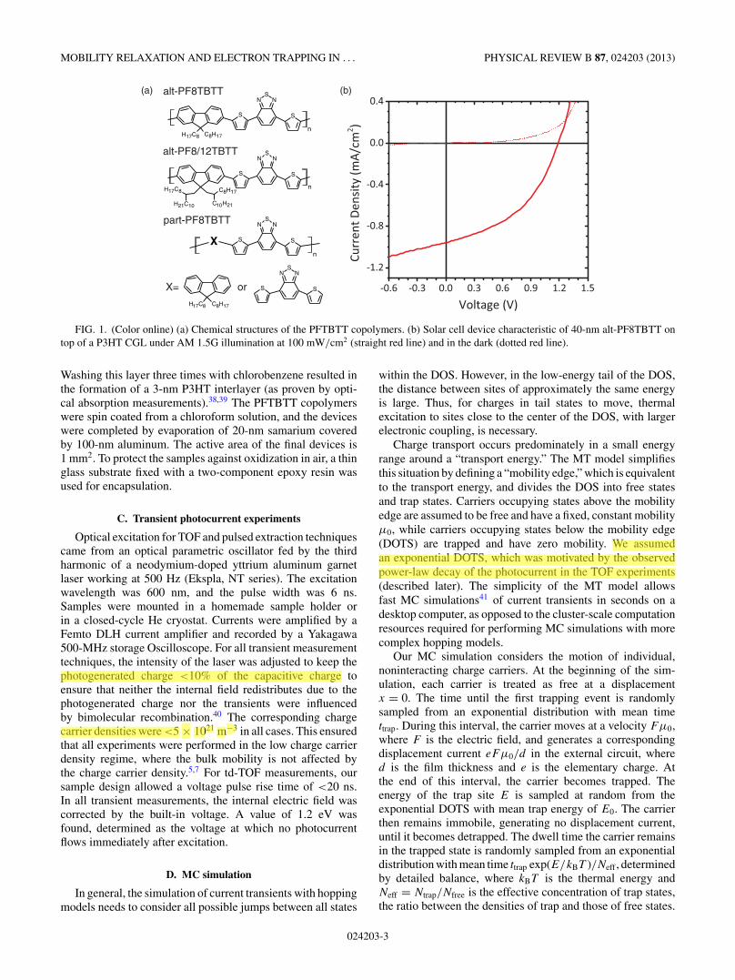
(a) alt-PF8TBTT
part-PF8TBTT
alt-PF8/12TBTT
X= or
SX
NS
N
S
n
S
NS
N
S
C8H17H17C8
S
NS
N
S
H17C8 C8H17n
S
NS
N
S
C10H21
C8H17
H21C10
H17C8n
(b)
FIG. 1. (Color online) (a) Chemical structures of the PFTBTT copolymers. (b) Solar cell device characteristic of 40-nm alt-PF8TBTT ontop of a P3HT CGL under AM 1.5G illumination at 100 mW/cm2 (straight red line) and in the dark (dotted red line).
Washing this layer three times with chlorobenzene resulted inthe formation of a 3-nm P3HT interlayer (as proven by opti-cal absorption measurements).38,39 The PFTBTT copolymerswere spin coated from a chloroform solution, and the deviceswere completed by evaporation of 20-nm samarium coveredby 100-nm aluminum. The active area of the final devices is1 mm2. To protect the samples against oxidization in air, a thinglass substrate fixed with a two-component epoxy resin wasused for encapsulation.
C. Transient photocurrent experiments
Optical excitation for TOF and pulsed extraction techniquescame from an optical parametric oscillator fed by the thirdharmonic of a neodymium-doped yttrium aluminum garnetlaser working at 500 Hz (Ekspla, NT series). The excitationwavelength was 600 nm, and the pulse width was 6 ns.Samples were mounted in a homemade sample holder orin a closed-cycle He cryostat. Currents were amplified by aFemto DLH current amplifier and recorded by a Yakagawa500-MHz storage Oscilloscope. For all transient measurementtechniques, the intensity of the laser was adjusted to keep thephotogenerated charge <10% of the capacitive charge toensure that neither the internal field redistributes due to thephotogenerated charge nor the transients were influencedby bimolecular recombination.40 The corresponding chargecarrier densities were <5 × 10²¹ m−3 in all cases. This ensuredthat all experiments were performed in the low charge carrierdensity regime, where the bulk mobility is not affected bythe charge carrier density.5,7 For td-TOF measurements, oursample design allowed a voltage pulse rise time of <20 ns.In all transient measurements, the internal electric field wascorrected by the built-in voltage. A value of 1.2 eV wasfound, determined as the voltage at which no photocurrentflows immediately after excitation.
D. MC simulation
In general, the simulation of current transients with hoppingmodels needs to consider all possible jumps between all states
within the DOS. However, in the low-energy tail of the DOS,the distance between sites of approximately the same energyis large. Thus, for charges in tail states to move, thermalexcitation to sites close to the center of the DOS, with largerelectronic coupling, is necessary.
Charge transport occurs predominately in a small energyrange around a “transport energy.” The MT model simplifiesthis situation by defining a “mobility edge,” which is equivalentto the transport energy, and divides the DOS into free statesand trap states. Carriers occupying states above the mobilityedge are assumed to be free and have a fixed, constant mobilityμ0, while carriers occupying states below the mobility edge(DOTS) are trapped and have zero mobility. We assumedan exponential DOTS, which was motivated by the observedpower-law decay of the photocurrent in the TOF experiments(described later). The simplicity of the MT model allowsfast MC simulations41 of current transients in seconds on adesktop computer, as opposed to the cluster-scale computationresources required for performing MC simulations with morecomplex hopping models.
Our MC simulation considers the motion of individual,noninteracting charge carriers. At the beginning of the sim-ulation, each carrier is treated as free at a displacementx = 0. The time until the first trapping event is randomlysampled from an exponential distribution with mean timettrap. During this interval, the carrier moves at a velocity Fμ0,where F is the electric field, and generates a correspondingdisplacement current eFμ0/d in the external circuit, whered is the film thickness and e is the elementary charge. Atthe end of this interval, the carrier becomes trapped. Theenergy of the trap site E is sampled at random from theexponential DOTS with mean trap energy of E0. The carrierthen remains immobile, generating no displacement current,until it becomes detrapped. The dwell time the carrier remainsin the trapped state is randomly sampled from an exponentialdistribution with mean time ttrap exp(E/kBT )/Neff , determinedby detailed balance, where kBT is the thermal energy andNeff = Ntrap/Nfree is the effective concentration of trap states,the ratio between the densities of trap and those of free states.
024203-3
fjaiser
Hervorheben
fjaiser
Hervorheben
fjaiser
Hervorheben
MARCEL SCHUBERT et al. PHYSICAL REVIEW B 87, 024203 (2013)
The trapping and detrapping process is repeated until thecharge carrier reaches the counter electrode x = d. Currenttransients were constructed by averaging 105 carriers to givenoise-free curves.
An effective mobility μeff of a charge carrier at anytime is given by the free carrier mobility multiplied bythe fraction of carriers in a free state. When simulatingtransient photocurrents with a long delay between excitationand extraction, it was necessary to include a field-dependentdetrapping rate to accurately fit the measured transients. Thiswas implemented by increasing the detrapping rate by a factorof exp(aF/kBT ) (up to aF = E). The fitting parameter a
loosely represents the typical hopping distance from a trapstate to a nearby free carrier state in the downfield direction.42
III. RESULTS AND DISCUSSION
A. Electron transport in alternating PF8TBTT
Two contradicting views of the charge transport propertiesof PFTBTT-based OFETs can be found in literature. Whilework by Muller et al.26 and Andersson et al.43 did notreveal electron transport in pristine PFTBTT OFETs, McNeillet al. nicely demonstrated ambipolar behavior of F8TBT ina light-emitting OFET.44 We performed OFET measurementsin bottom gate–top electrode geometry with a silanized SiO2
gate insulator (displayed in Fig. S1 of the supplementarymaterial),71 which clearly showed ambipolar charge transportin alt-PF8TBTT and reveal mobilities for holes and electrons ofμh = 2 × 10⁻³ cm2V−1s−1 and μe = 4 × 10⁻⁴ cm2V−1s−1,respectively, that are comparable to those reported in Ref. 44.Therefore, we conclude here that alt-PF8TBTT can be re-garded as an ambipolar material with overall good electrontransport, consistent with the observation of the excellentacceptor properties of alt-PF8/12TBTT in organic solar cells,where sufficiently high electron mobility is a prerequisite.23
In order to address bulk transport properties of alt-PF8TBTT, we applied different transient photocurrent tech-niques. A common technique for determining charge carriermobilities is the photo-CELIV technique.45 Here, photo-generated charges are continuously accelerated by a linearincreasing voltage. Given a homogeneous charge carrierdensity, extraction of charge carriers at one side of the devicesets in simultaneously, leading to a characteristic maximumin the current signal from which the electron mobility canbe calculated. In addition, the delay time between the pulsedexcitation and the beginning of the extraction pulse tdel can bevaried, which allows the investigation of charge recombinationor charge relaxation phenomena. The advantage of CELIV isthat it can be applied to thin organic layers of some 100 nm.Thus, charge transport can be studied on spatial and temporaldimensions that are relevant for active devices like solar cellsor LEDs.
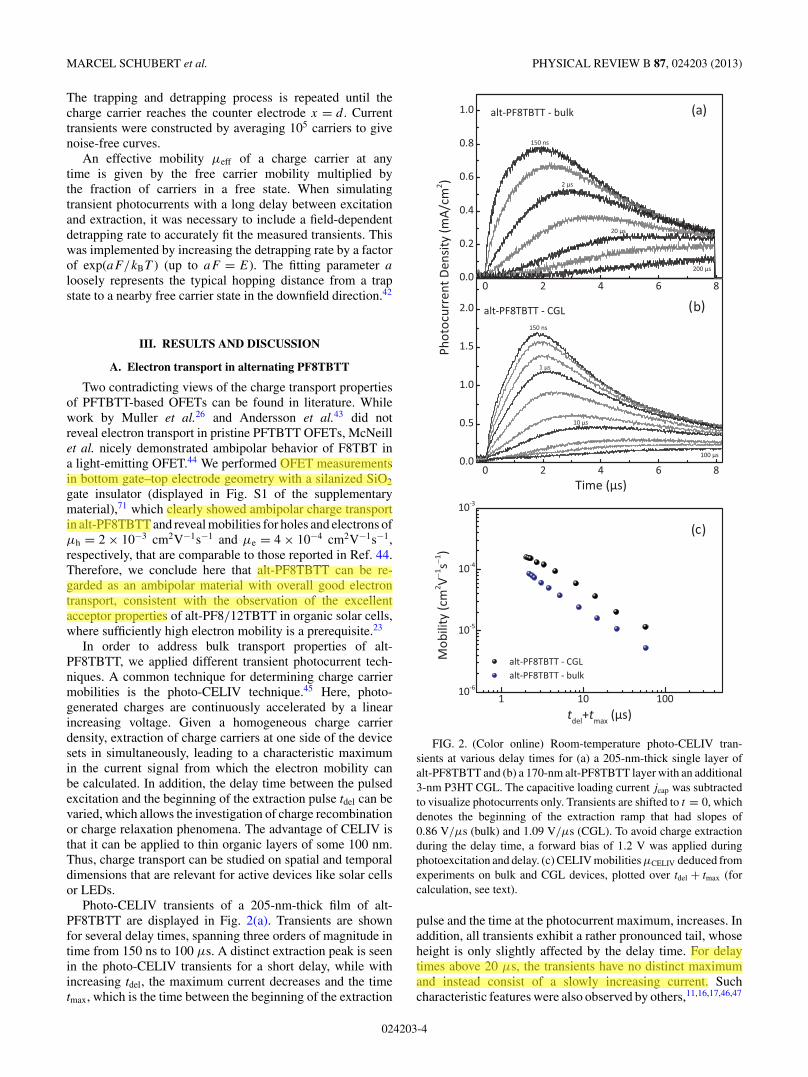
Photo-CELIV transients of a 205-nm-thick film of alt-PF8TBTT are displayed in Fig. 2(a). Transients are shownfor several delay times, spanning three orders of magnitude intime from 150 ns to 100 μs. A distinct extraction peak is seenin the photo-CELIV transients for a short delay, while withincreasing tdel, the maximum current decreases and the timetmax, which is the time between the beginning of the extraction
FIG. 2. (Color online) Room-temperature photo-CELIV tran-sients at various delay times for (a) a 205-nm-thick single layer ofalt-PF8TBTT and (b) a 170-nm alt-PF8TBTT layer with an additional3-nm P3HT CGL. The capacitive loading current jcap was subtractedto visualize photocurrents only. Transients are shifted to t = 0, whichdenotes the beginning of the extraction ramp that had slopes of0.86 V/μs (bulk) and 1.09 V/μs (CGL). To avoid charge extractionduring the delay time, a forward bias of 1.2 V was applied duringphotoexcitation and delay. (c) CELIV mobilities μCELIV deduced fromexperiments on bulk and CGL devices, plotted over tdel + tmax (forcalculation, see text).
pulse and the time at the photocurrent maximum, increases. Inaddition, all transients exhibit a rather pronounced tail, whoseheight is only slightly affected by the delay time. For delaytimes above 20 μs, the transients have no distinct maximumand instead consist of a slowly increasing current. Suchcharacteristic features were also observed by others,11,16,17,46,47
024203-4
fjaiser
Hervorheben
fjaiser
Hervorheben
fjaiser
Hervorheben
fjaiser
Hervorheben
MOBILITY RELAXATION AND ELECTRON TRAPPING IN . . . PHYSICAL REVIEW B 87, 024203 (2013)
but their origin has not been discussed so far. In the lowcarrier density regime, the corresponding mobility μCELIV isobtained via μCELIV = 2d2[3t2
maxA′]−1, where A′ is the voltage
rise speed.48 The calculated mobility as a function of delaytime is displayed in Fig. 2(c). This plot shows a continuousdecrease of μCELIV with increasing delay time. This decay, aswell as the unusual shape of the current transients, suggeststhat the mobility must be a function of time throughout theentire temporal range considered here. In this context, theinitial rise of the CELIV transients is highly nonlinear forshort delay times, in contrast to the predicted linear rise for atime- and field-independent mobility.48 Note that, the natureof the mobile (faster) charge carrier type, either electron orhole, can in general distinguished in a CELIV experiment, andboth carrier types can significantly contribute to the current.49
Indeed, our OFET measurements suggest that in alt-PF8TBTT,both types of charge carriers are mobile, which thereforerepresents a fundamental problem whenever photogeneratedcarriers are generated over the entire layer thickness. Thus,the understanding of the current transient and a definitiveidentification of the electron transport in alt-PF8TBTT is,at this point, not possible and requires a more sophisticatedmeasurement technique.
An elegant approach to avoid the difficulties of the standardCELIV measurement in distinguishing charge carrier types isto insert a CGL.50 Here, a thin photoactive layer is inserted intothe device structure to create a planar heterojunction (PHJ)between the CGL and the transport layer, the latter being thematerial under study. After excitation, excitons predominantlydissociate at the PHJ, generating free charge carriers. Thepolarity of the generated carriers inside the transport layerdepends only on the relative position of the energy levelsbetween generation and transport layer. As a further benefit ofthe CGL technique, the optical field profile within the devicemay not be known for the exact analysis of the transients, sincefree charge generation is almost exclusively at the PHJ.50 Here,we apply this technique to measure carrier mobilities in thinpolymer layers <200 nm using photo-CELIV and TOF, wherefor the latter technique, several-micrometer-thick layers arenormally required.
To study electron transport in PFTBTT copolymers, weintroduced a P3HT CGL between the PEDOT:PSS anode andthe PFTBTT transport layer. In this combination, the CGL actsas a donor while PFTBTT represents the electron-acceptingand electron-transporting phase.23,44,51 A typical current–voltage characteristic of a solar cell device comprising a 3-nmP3HT CGL and a 40-nm- thin alt-PF8TBTT layer is displayedin Fig. 1(b). This cell gives a reasonable PCE of 0.5% under100 mW/cm2 air mass 1.5 global (AM 1.5G) illumination witha short circuit current density of ∼1 mA/cm2. In addition, theexternal quantum efficiency at the excitation wavelength of600 nm of this device is ∼100 times higher than of adevice without CGL. This demonstrates that the photocurrentoriginates from free carriers generated at the PHJ.
Photo-CELIV current transients of devices comprising aP3HT CGL recorded over the range of delay times, as for thebulk device, are displayed in Fig. 2(b). The general character-istics of the photocurrent are comparable for the CGL and thebulk device, including the strong shift of tmax with increasingtdel, the pronounced tail at the end of the extraction pulse, and
the slowly increasing current at high delay times. This resultstrongly implies that electrons also determine the transient cur-rent in the bulk photo-CELIV experiment. The correspondingelectron mobility values were extracted from the maximum ofthe photo-CELIV transient tmax in the CGL device. Assumingthat charges are generated only at the interface to the thinCGL and accelerated by a linear increasing field E(t) = A′t/dwith a slope of A′, the mobility is simply derived from s(t) =∫
v(τ )dτ = μ∫
E(τ )dτ . Assuming that s(tmax) = d yields
μCELIV,CGL = 2d2
t2maxA
′ . (1)
This formula is correct in that the CGL is much thinnerthan the layer thickness d and that the photogeneratedcharge is much smaller than the capacitive charge storedat the electrodes Qphoto � Qcap (see also Fig. S2 of thesupplementary material).71 The latter condition rules out thatspace charges distort or screen the external applied field.Equation (1) differs by a factor of 1/3 from the case of aninitially homogeneously distributed charge density. Mobilitiesobtained by Eq. (1) are displayed in Fig. 2(c). Again, themobility drops continuously over a time span of two ordersof magnitude, following a power-law decay with an exponentof ∼0.81 ± 0.01. To summarize, the photo-CELIV transientsin bulk and CGL devices both reflect the electron transportcharacteristics of alt-PF8TBTT and reveal a pronouncedmobility relaxation over two orders in time.
One drawback of photo-CELIV is that extraction is witha nonconstant, linearly rising electric field. Therefore, caremust be taken when interpreting CELIV transients, wherethe photocurrent maximum appears at different times andconsequently at different electric fields. To circumvent thisproblem, we performed experiments using the td-TOF method.Here, a rectangular voltage pulse is applied to the sampleafter an adjustable delay time. Thus, this technique mergesadvantages of photo-CELIV and TOF. To the best of ourknowledge, this is the first time that transport dynamics havebeen investigated using the td-TOF technique. A detaileddescription of the setup and working principle can be found ina recent publication by Kniepert et al.52
Experimental td-TOF transients are displayed in Fig. 3,together with the standard TOF transient for a P3HT CGLdevice with a 170-nm-thick alt-PF8TBTT layer. The topelectrode was positively charged to probe the transport ofelectrons. No transients were detected when the polarity ischanged, which proves that electrons are efficiently generatedat the CGL and transported through the alt-PFTBTT layer.In td-TOF, a constant voltage of 1.2 V was applied duringthe delay time as in the CELIV experiment to avoid carrierextraction. Then, the voltage is switched to − 0.5 V (topelectrode positively charged within 20 ns) to create anextraction field. The same voltage of − 0.5 V was appliedin the regular TOF experiment.
The regular TOF current transient displayed in Fig. 3is strongly dispersive, and its initial decay follows a strictpower-law dependence of j (t) ∝ tα−1. As pointed out in Sec. I,such time dependence is characteristic for charge transportthat is dominated by MT and detrapping in an exponentialDOS distribution g(E) = Ntk
−1B T −1
0 exp[−(EL − E)/(E0)] of
024203-5
fjaiser
Hervorheben
fjaiser
Hervorheben
fjaiser
Hervorheben
fjaiser
Hervorheben
fjaiser
Hervorheben
fjaiser
Hervorheben
fjaiser
Hervorheben
fjaiser
Hervorheben
fjaiser
Hervorheben
fjaiser
Hervorheben
MARCEL SCHUBERT et al. PHYSICAL REVIEW B 87, 024203 (2013)
FIG. 3. TOF (black) and td-TOF (light and dark gray) currenttransients at a temperature of 295 K and an extraction field of 1 ×10⁷ V/m. td-TOF transients are shown for several delay times todisplay the increase in the transit time. The thickness of the alt-PF8TBTT active layer was 170 nm. Straight lines are a visual guidefor the two linear regions.
trapping states, where Nt is the total DOTS, E0 = kBT0 isthe characteristic energy, EL is the energy of the lowestunoccupied molecular orbital, kB is Boltzmann’s constant, andT0 is the characteristic temperature.13 The slope parameterα is then given by α = T/T0. For the data shown in Fig. 3,the double-logarithmic slope m = α − 1 = −(1 − kBT/E0) isequal to −0.62, which yields E0 67 meV for alt-PF8TBTT,corresponding to a characteristic temperature of 775 K. In thismodel, the current at a given time is directly proportional tothe effective mobility in the organic semiconductor. In otherwords, the power-law decay of the current reflects the timedependence of the mobility. Above 1 μs, the TOF transient’sslope changes, indicative of the arrival of the fastest electronsat the counter electrode. At an internal field of 1 × 10⁷ V/m,the transit time of the electrons is ∼1 μs. From this, theelectron mobility was calculated to be 1.7 × 10⁻⁴ cm2/Vs,close to the mobility obtained by photo-CELIV measurementsat very short delay times [Fig. 2(c)]. This value for the electronmobility is even higher than reported bulk hole mobilities inpure PFTBTT,27 showing that in the bulk, electrons might bethe faster type of charge carriers. The small thickness of 3 nmand the high hole mobility in regioregular P3HT of ∼1 ×10⁻⁴ cm2/Vs53 sets the transit time of holes in the CGL to∼1 ns, orders of magnitude faster than the observed transittime, again confirming that we are able to probe exclusivelythe electron transport through the alt-PF8TBTT layer.
For short delay times, td-TOF and TOF show comparablecurrent transients with similar transit times. With increasingdelay time, the initial slope of the td-TOF transient decreasesand reaches a nearly constant value at a delay time of 10 μs.Also, the change in slope is seen at later times, suggestinga larger transit time. This is exemplarily shown in Fig. 3for the td-TOF transient after a 2-μs delay. The calculatedmobility is 7 × 10⁻⁵ cm2/Vs, which is comparable to thevalue obtained by photo-CELIV at the same delay. Thus, ourtd-TOF measurements unambiguously reveal a pronouncedtime dependence of the mobility.
B. Simulation of current transients
The qualitative agreement between the results from td-TOF(constant field) and those from photo-CELIV (linearly increas-ing field) measurements as described previously suggests thattime-dependent electron mobility in an exponential DOTSrather than its explicit field dependence governs the CELIVtransients at different delay times. To confirm this, a numericalMC simulation based on a MT model was used to simulate themeasured current transients. The algorithm of the simulationis described is Sec. II D, and best fits are displayed in Fig. 4.The parameters used for these simulations are summarized inTable I and were determined as follows. First, the initial currentdecay m of the TOF transient in Fig. 3 is used to fix the trapenergy E0 to 67 meV. In a next step, the free carrier mobilityμ0, the trap time ttrap, and the effective trap density Neff werechosen to accurately reproduce photo-CELIV transients at veryshort delay times. Then ttrap and Neff were fixed. Finally,the parameter a describing the field-assisted detrapping is
(a)
(b)
FIG. 4. (Color online) Comparison of MC simulation resultswith measured transients obtained by (a) TOF and td-TOF and(b) photo-CELIV. The data are taken from Figs. 2 and 3. Delaytimes are indicated at each transient. Inset (a): Room-temperatureTOF transients of CGL devices with a 170- and a 100-nm-thick alt-PF8TBTT layer at a field of 1 × 10⁷ and 5 × 10⁶ V/m, respectively.The dotted lines represent the extension of the initial current decaywith a slope of m = −0.62. Inset (b): Photo-CELIV transients aftera 150-ns delay at 308, 287, 269, 256, and 238 K.
024203-6
fjaiser
Hervorheben
fjaiser
Hervorheben
fjaiser
Hervorheben
fjaiser
Hervorheben
fjaiser
Hervorheben
MOBILITY RELAXATION AND ELECTRON TRAPPING IN . . . PHYSICAL REVIEW B 87, 024203 (2013)
TABLE I. Fit parameters used for the simulation in Fig. 4.
Parameter Description Value
ttrap Trap time 0.5 nsE0 Trap energy 67 meVNeff DOTS/density of free states 0.05μ0 Free carrier mobility 2.3·10−3 cm2V−1s−1
(TOF)2.8·10−3 cm2V−1s−1
(CELIV)a Field activation length 1.1 nmd Active layer thickness 170 nmF Extraction field (TOF, td-TOF) 1 × 10⁷ V/mA′ Voltage ramp (photo-CELIV) 1.09 V/μs
introduced into the simulation by fitting the long delay timetransients, while μ0 was allowed to slightly vary until allphoto-CELIV transients were accurately described with thesame set of parameters. The mobility is treated as fieldindependent, in good agreement with our measurements (seeFig. S3 of the supplementary material).71 Every feature of theexperimental photo-CELIV transients for different delay timesand temperatures is reproduced by the simulation, includingthe pronounced shift of the current maximum with increasingdelay, which resembles the power-law mobility decay shownin Fig. 2(c). The simulation also reproduced TOF and td-TOFdata with the same set of parameters. Here, the current of asecond device with an active layer thickness of only 100 nmis shown for comparison. This demonstrates that the MT modelwith an exponential trap distribution provides an excellentdescription of the data for all experimental techniques,temperatures, and delay times considered here. Regardingthe physical meaning of the simulation parameters, the threeparameters μ0, ttrap, and Neff do not define a unique set ofparameters, meaning that a change of one of these parameterscan be compensated by the other to give the same transient.Rather, it is the experimentally found trap energy E0 thatcritically determines the width and tail of the photo-CELIVtransients. Thus, E0 determines not only the slope of thephotocurrent decay in TOF measurements but also the primaryshape of the photo-CELIV transients, which unequivocallyconnects the different experimental techniques investigatedhere by this single parameter.
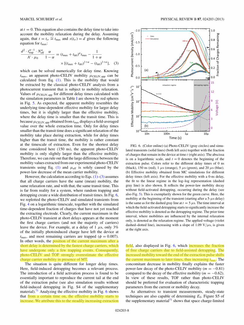
The good agreement between the measured and thesimulated data allows us to explore general aspects of theinfluence of charge carrier trapping on transient photocurrentexperiments. A dominant feature of the td-TOF transientsis the reduced initial slope of the current with increasingdelay time, which is quite well reproduced by the simulation.The reason for this is that for a power-law decay, the rateat which mobility changes with time becomes smaller forincreasing delay. Therefore, the mobility in a sample measuredafter prolonged delay is nearly constant on the timescaleof carrier extraction, and so is the initial photocurrent in alog–log presentation. The same phenomenon should affectphoto-CELIV measurements, where we observe a rather linearincrease of the initial photocurrent with extraction time afterlong delay, indicative of a constant mobility.
Surprisingly, although the shape of the photo-CELIVtransients is reproduced with great accuracy by the simulation,mobilities extracted from the photo-CELIV (and td-TOF)transients for different delays are about one order of magnitudelarger than the effective mobility μeff of the charge carriersat time tdel + tmax. In accordance to the MT model, μeff isdefined as the product of the fraction of free charge carrierstimes the free carrier mobility μeff = μ0 · φ and is obtaineddirectly from the simulation by calculating the fraction ofthe mobile (free) charge concentration to the overall chargeconcentration, φ = Nfree/(Nfree + Ntrap) (black solid line inFig. 5). Furthermore, the mobility decay in the simulation (andin the initial TOF transients) perfectly matches a power-lawdecay with an exponent of m = −0.62, while the mobilitydecay derived from the maximum of the photo-CELIVtransients with increasing delay time is much faster (slopeof m = −0.81, Fig. 5). We might propose that the overalllarger mobility derived from the photo-CELIV experimentis due Eq. (1) assuming a constant mean carrier mobility.However, for a power-law decay, the carrier mobility mightbe substantially higher at the beginning of the voltage rampthan at tmax. To address this issue, we derived an expressionfor tmax in considering the mobility relaxation due by a MTprocess. For this, the time-dependent effective mobility hasbeen parameterized by
μ(t + tdel) = μ0 · ((t + tdel)/ttrap)α−1. (2)
Using the parameters from Table I, Eq. (2) perfectly resemblesthe effective mobility obtained from the MC simulation. Theaverage path length s of a carrier drifting in a time-dependentelectric field E(t) with a time-dependent mean mobility iss(t) = ∫ t
FIG. 5. (Color online) Comparison of the measured and simulatedmobility relaxation. Black spheres display mobilities from measuredphoto-CELIV transients. The effective mobility obtained from theMC simulation is shown as a black solid line, while the solidred line displays the best fit of the time-dependent mobility to apower-law relaxation according to Eq. (2). Red spheres are thecorrespondent apparent photo-CELIV mobilities μCELIV,app, whichare obtained by applying Eq. (1) to the transit time according toEq. (3). The dashed gray line visualizes the power-law decay of themeasured mobility, where the exponent was found to be m = −0.81.For clarity, the simulation was performed without assuming field-activated detrapping, which is shown in Fig. 6.
024203-7
fjaiser
Hervorheben
fjaiser
Hervorheben
MARCEL SCHUBERT et al. PHYSICAL REVIEW B 87, 024203 (2013)
at t = 0. This equation also contains the delay time to take intoaccount the mobility relaxation during the delay. Assumingagain, that t = ttr ∼= tmax and s(ttr ) = d gives the followingequation for tmax:
d2 · tα−1trap · Nα
eff
A′ · μ0
α
1 − α= (tmax + tdel)
αtmax − 1
1 + α
× [(tmax + tdel)1+α − (tdel)
1+α], (3)
which can be solved numerically for delay time. Knowingtmax, an apparent photo-CELIV mobility μCELIV,app can becalculated from Eq. (1). This is the mobility that wouldbe extracted by the classical photo-CELIV analysis from aphotocurrent transient that is subject to mobility relaxation.Values of μCELIV,app for different delay times calculated withthe simulation parameters in Table I are shown by red spheresin Fig. 5. As expected, the apparent mobility resembles theunderlying time-dependent effective mobility for larger delaytimes, but it is slightly larger than the effective mobility,where the delay time is smaller than the transit time. This isbecause μCELIV,app obtained from tmax displays a field-averagedvalue over the whole extraction time. Only for delay timessmaller than the transit time does a significant relaxation of themobility take place during extraction, while for delay timeshigher than the transit time, the mobility is rather constantat the timescale of extraction. Even for the shortest delaytime considered here (150 ns), the apparent photo-CELIVmobility is only slightly larger than the effective mobility.Therefore, we can rule out that the large difference between themobility values extracted from our experimental photo-CELIVtransients using Eq. (1) and μeff is solely caused by thepower-law decrease of the mean carrier mobility.
However, the calculation according to Eqs. (1)–(3) assumesthat all charge carriers have the same (mean) mobility, thesame relaxation rate, and with that, the same transit time. Thisis far from reality for a system, where random trapping anddetrapping create a wide distribution of transit times. In Fig. 6,we replotted the photo-CELIV and simulated transients fromFig. 4 on a logarithmic timescale, together with the simulatedtime-dependent fraction of charges that have not yet reachedthe extracting electrode. Clearly, the current maximum in thephoto-CELIV transient at short delays appears at the momentthe first charge carriers (and not the majority of carriers)leave the device. For example, at a delay of 1 μs, only 3%of the initially photoinduced charge have left the device attmax, and most remaining carriers are trapped (φ = 0.007).In other words, the position of the current maximum after ashort delay is determined by the fastest charge carriers, whichhave undergone only a few trapping events. Consequently,photo-CELIV and TOF strongly overestimate the effectivecharge carrier mobility in presence of MT.
The situation is quite different for longer delay times.Here, field-induced detrapping becomes a relevant process.The introduction of a field activation process is found to beessentially important to reproduce the current tail at the endof the extraction pulse (see also simulation results withoutfield-induced detrapping in Fig. S4 of the supplementarymaterial).71 Analyzing the effective mobility in Fig. 6 showsthat from a certain time on, the effective mobility starts toincrease. We attribute this to the steadily increasing extraction
(a)
(b)
FIG. 6. (Color online) (a) Photo-CELIV (gray circles) and simu-lated transients (solid lines) (both left axis) together with the fractionof charges that remain in the device at time t (right axis). The abscissais on a logarithmic scale, and t = 0 denotes the beginning of theextraction pulse. Colors refer to the different delay times of 0 ns(black), 150 ns (red), 1 μs (orange), 5 μs (green), and 20 μs (blue).(b) Effective mobility obtained from MC simulations for differentdelay times (left axis). For the effective mobility with a 0-ns delay,the fit to the linear regime in the log–log representation (dashedgray line) is also shown. It reflects the power-law mobility decaywithout field-activated detrapping, occurring during the delay (seealso Fig. 5). This is exemplarily shown for the green curve. Here, themobility at the beginning of the transient (starting after a 5-μs delay)is the same as for the dashed gray line at t = 5 μs. The time interval atwhich the field-activated detrapping starts to significantly increase theeffective mobility is denoted as the detrapping regime. The prior timeinterval, where mobilities are influenced by the internal relaxationonly, is denoted as the relaxation regime. The applied voltage (violetdashed–dotted line), increasing with a slope of 1.09 V/μs, is givenat the right axis.
field, also displayed in Fig. 6, which increases the fractionof free charge carriers due to field-assisted detrapping. Theincreased mobility toward the end of the extraction pulse shiftsthe current maximum to later times, thus increasing tmax. Theconcomitant decrease in mobility finally explains the fasterpower-law decay of the photo-CELIV mobility (m = −0.81)compared to the decay of the effective mobility (m = −0.62).In view of these results, TOF rather than photo-CELIVshould be preferred for evaluation of characteristic trappingparameters from the current or mobility decay.
As alternatives to transient measurements, steady-statetechniques are also capable of determining E0. Figure S5 ofthe supplementary material71 shows that space charge-limited
024203-8
fjaiser
Hervorheben
fjaiser
Hervorheben
fjaiser
Hervorheben
fjaiser
Hervorheben
fjaiser
Hervorheben
MOBILITY RELAXATION AND ELECTRON TRAPPING IN . . . PHYSICAL REVIEW B 87, 024203 (2013)
currents of alt-PF8TBTT electron-only devices54 can be welldescribed with a model developed by Mark and Helfrich,55
with an exponential trap state distribution that is comparable tothe one deduced from the simulation of the current transients.This further demonstrates that the processes that determinecharge transport in the presence of electronic trap states areindependent of the origin of the charge carriers, either injectedor photogenerated, and can be consistently described withinthe framework of MT and release.
C. Origin of the electron traps
After having demonstrated the pronounced influence oftrapping on the electron transport in alt-PF8TBTT, finding theorigin of these trap states is of great interest. Because chemicalimpurities, e.g., residual catalyst or imperfect endcappingof polymer chains, can likely influence the charge transportof alt-PF8TBTT, we carefully revisited the synthetic proce-dures. For this purpose, two independent polymer batcheswere synthesized, from which one was further purified.56
In addition, a third batch was provided by a collaboratinglaboratory. However, all three batches showed the sametransport characteristics, as described in the previous section.We therefore rule out chemical impurities. This raises thequestion of whether trap formation is related to the specificmolecular structure of the copolymer. Therefore, two differentpolymers with either the same polymer backbone but differentside chains or the same side chain but a modified polymerbackbone were synthesized. The former of these two polymers,alt-PF8/12TBTT, is a alternating PFTBTT with branchedoctyldodecyl side chains, while the latter, stat-PF8TBTT,contains octyl side chains and shows a partial statisticalvariation along the backbone (for details, see Sec. II A andFig. 1). Here, the regular alternation of the donor and acceptorunit, as it is for alt-PF8TBTT, is disturbed by replacing afew fluorene units by TBTT segments. In Fig. 7, the photo-CELIV transients of alt-PF8/12TBTT and part-PF8TBTTCGL devices are shown for varying delay times. In contrastto the results obtained for the alt-PF8TBTT (Fig. 2), thecurrent maximum of the two modified PFTBTT copolymersdo not shift with increasing delay time. Furthermore, a distinctmaximum can be observed also for high delay times of 100 μs.This means that the mobility is constant in time (at least withinthe observable time range from 150 ns to 100 μs). This revealsan important structure–property relationship for this type ofcopolymer. Emphasizing that for all polymers investigatedhere the synthesis, as well as the device preparation andmeasurement, is carried out under the same conditions, weinfer that the severe mobility relaxation in alt-PF8TBTT isrelated to its specific molecular structure. The comparison ofalt-PF8TBTT and alt-PF8/12TBTT shows that the mobilityrelaxation on the microsecond timescale disappears whenlong and branched rather than linear side chains are attachedto the PFTBTT backbone. Interestingly, despite its longerside chains, alt-PF8/12TBTT exhibits significantly higherphoto-CELIV mobilities than does alt-PF8TBTT. However,mobility relaxation on the timescale measured here is alsosuppressed when the strict alternation of the donor andacceptor unit is slightly disturbed, as seen for part-PF8TBTT.This clear correlation between the backbone structure and the
(a)
(b)
(c)
FIG. 7. (Color online) Room-temperature photo-CELIV tran-sients at various delay times for (a) a 200-nm-thick layer of alt-PF8/12TBTT and (b) a 170-nm layer of part-PF8TBTT. In bothdevices, a 3-nm P3HT CGL was used. The capacitive loading currentwas subtracted to visualize photocurrents only. To avoid chargeextraction during the delay time, a forward bias of 1.2 V was applied.(c) Mobility calculated via Eq. (1) plotted over tdel + tmax, togetherwith the mobility of the alt-PF8TBTT CGL device displayed in Fig. 2.
specific transient transport properties rules out that the mobilityrelaxation observed for alt-PF8TBTT is caused to extrinsicimpurities.
IV. DISCUSSION
In this paper, we examine the charge transport in thedonor/acceptor copolymer alt-PF8TBTT, which has beenwidely applied in organic solar cells. A pronounced relaxation
024203-9
fjaiser
Hervorheben
fjaiser
Hervorheben
fjaiser
Hervorheben
fjaiser
Hervorheben
fjaiser
Hervorheben
fjaiser
Hervorheben
MARCEL SCHUBERT et al. PHYSICAL REVIEW B 87, 024203 (2013)
of the electron mobility is unambiguously proven by threetransient photocurrent techniques and is the most importantfeature of the experiments described here. It continues over aperiod of at least 100 μs and is likely caused by an energeticthermalization process that follows photogeneration of freecharge carriers inside the organic semiconductor.
Thermalization of photogenerated charge carriers and time-dependent mobilities has been rarely observed for conju-gated polymers.11,14–17,46,57 Osterbacka et al. assigned thetime-dependent mobility observed in regiorandom P3HT tooriginate from thermalization of hot, photogenerated carrierswithin the Gaussian DOS.46 According to Pautmeier et al.,the relaxation to the thermodynamic equilibrium proceedsvia a decrease in carrier mobility; however, in the case ofa Gaussian DOS, it is also accompanied by a later transitionto constant equilibrium mobility.58 This so-called transitionfrom the dispersive to nondispersive regime is predicted toshift to shorter times with increasing temperature or smallerenergetic disorder, but this effect has, to best of our knowledge,not yet been observed for conjugated polymers. Recently, weshowed that recombination of photogenerated charges at highcarrier densities can alter photo-CELIV current transients andlead to an apparent time dependence of the CELIV mobility.40
As the shapes of our photo-CELIV transients are independentof intensity, recombination phenomena during extraction areexpected to be insignificant (see Figs. S6 and S7 of thesupplementary material71).59
A model that is able to describe the continuous mobilityrelaxation as observed here is MT formalism, which wastheoretically described by Orenstein and Kastner for anexponential DOTS.13,60 Beside the ongoing mobility decrease,direct evidence for MT comes from the power-law decay ofthe TOF transients on timescales less than the transit time. Tofurther support this, MC simulations of MT in one dimensionwere performed. These simulations reproduce the power-lawdecay of the effective mobility. Furthermore, experimentaltransients of several techniques and for various parameters(delay time and temperature) can be described with a singleset of parameters. Thus, we are able to explain the anomalousshape of photo-CELIV transients entirely by MT, acting onthe transport of a single charge carrier type only.
Our results also allow us to speculate about the originof electron traps in the alt-PF8TBTT copolymer. Chemicaldefects that act as electronic trap states, i.e., hydrated oxygencomplexes, were recently proposed by Nicolai et al. torationalize widely observed trap-limited electron currents inmany semiconducting polymers, including alt-PF10TBTT.61
Furthermore, Kuik et al. demonstrated that the prominentketo defect in poly(9,9-dioctylfluorene) (PF8),62,63 createdthrough oxidation of a fluorene monomer, also acts as efficientelectron trap.64 However, these authors already observe a trap-dominated electron current for defect-free PF8. In contrast,the results of the previous section show that rather smallchanges of the molecular structure of either the side chainsor the backbone of the PFTBTT copolymer investigated herecauses the disappearance of the mobility relaxation, making itunlikely that the electron traps are originating from doping,chemical defects, or impurities. Thus, we suppose that inour case, the electron traps causing the mobility relaxation inalt-PF8TBTT must be related to the microscopic morphology
or the molecular design of the copolymer itself. It was recentlynoted that solar cells of the high-performance donor ma-terial poly[N-9′-hepta-decanyl-2,7-carbazole-alt-5,5-(4′,7′-di-2-thienyl-2′,1′,3′-benzothiadiazole)] (PCDTBT) may sufferfrom significant intrinsic trapping of free charge carriers, intro-duced by morphological changes of the PCDTBT phase.65,66
Here, we note the great chemical similarity of PCDTBTand alt-PF8TBTT, only differing by two atoms (the nitrogenor carbon atom at the bridge position of the carbazole orfluorene monomer, respectively, and an additional carbonatom that mediates the dioctyl substitution with the bridgingnitrogen atom in PCDTBT). Through measurement of theparacrystalline disorder and in combination with densityfunctional theory-based molecular simulations, a connectionbetween the microscopic morphology and the development ofexponentially distributed trap states was also recently proposedby Rivnay et al.67
An alternative explanation for the particular trappingproperties of alt-PF8TBTT arises from work by Dieckmannet al. These authors showed that the electrostatic interactionsof transport sites and randomly oriented dipoles can cause asignificant broadening of the DOS.68 Such permanent dipolesmight be created via intermolecular coulombic interactionsbetween the electron-attracting TBTT (acceptor) unit and theelectron-withdrawing fluorene (donor) group of neighboringchains, driven by π–π stacking. A particularly favorable situ-ation would occur if neighboring chains in a stack were shiftedby half a repeat unit, a pattern that may be introduced due to thesp3 hybridization of the side chain-containing bridging atom,which forces the side chains to stick out of the plane of thepolymer backbone.21 The regular donor/acceptor stacking andthe proximity of neighboring chains might be altered by attach-ing longer side chains (as in alt-PF8/12TBTT) or by disturbingthe regular alternation of donor and acceptor units alongthe backbone (as in part-PF8TBTT). In this context, otherdioctyl-substituted fluorene copolymers show pronouncedelectron trapping. Namely, electron trapping is demonstratedfor pure poly(9,9′-dioctylfluorene-co-benzothiadiazole),47,54
F8TBT,29,30 and finally, in this study, for alt-PF8TBTT. Incontrast copolymers that perform best in devices carry longeror branched substituents.19–21,23,69,70
V. CONCLUSIONS
We performed various transient photocurrent experimentson a model donor/acceptor copolymer. Our measurementsreveal time-dependent electron mobility. The origin of thestrong mobility relaxation was identified by a multiple trappingmodel–based MC simulation and is explained by the signifi-cant trapping of electrons. It is further demonstrated that theelectron trapping has a severe influence on the shape of thecurrent transients. Chemical modifications of the polymersstructure revealed the origin of the electron trapping to berelated to the molecular structure, specific morphology, orboth of the copolymer. Our results show that small changesof the molecular design of donor/acceptor copolymers canintroduce electronic trap states with severe impact on theircharge transport properties.
024203-10
fjaiser
Hervorheben
fjaiser
Hervorheben
fjaiser
Hervorheben
fjaiser
Hervorheben
MOBILITY RELAXATION AND ELECTRON TRAPPING IN . . . PHYSICAL REVIEW B 87, 024203 (2013)
ACKNOWLEDGMENTS
The authors thank Sylvia Janietz (Frauenhofer Institute forApplied Polymer Research, Potsdam) for providing a batchof alt-PF8TBTT, and Heinz Bassler and Anna Kohler for
directing our attention to the influence of dipolar interactionson charge transport. We also acknowledge laboratory assis-tance by Steffen Roland. M.S. and E.P. acknowledge fundingby the German Research Foundation within Priority ProgramNo. SPP 1355.
1H. Bassler, Phys. Status Solidi B 175, 15 (1993).2T. Tiedje and A. Rose, Solid State Comm. 37, 49 (1981).3P. W. M. Blom and M. Vissenberg, Mater. Sci. Eng. R Rep. 27, 53(2000).
4C. Tanase, E. J. Meijer, P. W. M. Blom, and D. M. de Leeuw, Phys.Rev. Lett. 91, 216601 (2003).
5W. F. Pasveer, J. Cottaar, C. Tanase, R. Coehoorn, P. A. Bobbert,P. W. M. Blom, D. M. de Leeuw, and M. A. J. Michels, Phys. Rev.Lett. 94, 206601 (2005).
6V. I. Arkhipov, P. Heremans, E. V. Emelianova, and H. Bassler,Phys. Rev. B 71, 045214 (2005).
7R. Coehoorn, W. F. Pasveer, P. A. Bobbert, and M. A. J. Michels,Phys. Rev. B 72, 155206 (2005).
8I. Lange, J. C. Blakesley, J. Frisch, A. Vollmer, N. Koch, andD. Neher, Phys. Rev. Lett. 106, 216402 (2011).
9J. Hwang, E. G. Kim, J. Liu, J. L. Bredas, A. Duggal, and A. Kahn,J. Phys. Chem. C 111, 1378 (2007).
10P. M. Borsenberger, L. Pautmeier, and H. Bassler, J. Chem. Phys.94, 5447 (1991).
11A. J. Mozer, G. Dennler, N. S. Sariciftci, M. Westerling, A. Pivrikas,R. Osterbacka, and G. Juska, Phys. Rev. B 72, 035217 (2005).
12R. U. A. Khan, D. Poplavskyy, T. Kreouzis, and D. D. C. Bradley,Phys. Rev. B 75, 035215 (2007).
13J. Orenstein and M. Kastner, Phys. Rev. Lett. 46, 1421 (1981).14A. Devizis, A. Serbenta, K. Meerholz, D. Hertel, and V. Gulbinas,
Phys. Rev. Lett. 103, 027404 (2009).15A. Devizis, K. Meerholz, D. Hertel, and V. Gulbinas, Phys. Rev. B
82, 155204 (2010).16A. Pivrikas, P. Stadler, H. Neugebauer, and N. S. Sariciftci, Org.
Electron. 9, 775 (2008).17M. Schubert, R. Steyrleuthner, S. Bange, A. Sellinger, and D. Neher,
Phys. Status Solidi A 206, 2743 (2009).18M. Svensson, F. L. Zhang, S. C. Veenstra, W. J. H. Verhees, J. C.
Hummelen, J. M. Kroon, O. Inganas, and M. R. Andersson, Adv.Mater. 15, 988 (2003).
19L. H. Slooff, S. C. Veenstra, J. M. Kroon, D. J. D. Moet,J. Sweelssen, and M. M. Koetse, Appl. Phys. Lett. 90, 143506(2007).
20M. H. Chen, J. Hou, Z. Hong, G. Yang, S. Sista, L. M. Chen, andY. Yang, Adv. Mater. 21, 4238 (2009).
21J. Liu, H. Choi, J. Y. Kim, C. Bailey, M. Durstock, and L. Dai, Adv.Mater. 24, 538 (2011).
22D. Veldman, S. C. J. Meskers, and R. A. J. Janssen, Adv. Funct.Mater. 19, 1939 (2009).
23D. Mori, H. Benten, J. Kosaka, H. Ohkita, S. Ito, and K. Miyake,ACS Appl. Mater. Interfac. 3, 2924 (2011).
24X. M. He, F. Gao, G. L. Tu, D. Hasko, S. Huttner, U. Steiner, N. C.Greenham, R. H. Friend, and W. T. S. Huck, Nano Lett. 10, 1302(2010).
25M. Koppe, H. J. Egelhaaf, G. Dennler, M. C. Scharber, C. J. Brabec,P. Schilinsky, and C. N. Hoth, Adv. Funct. Mater. 20, 338 (2010).
26C. Muller, E. G. Wang, L. M. Andersson, K. Tvingstedt, Y. Zhou,M. R. Andersson, and O. Inganas, Adv. Funct. Mater. 20, 2124(2010).
27D. J. D. Moet, M. Lenes, J. D. Kotlarski, S. C. Veenstra,J. Sweelssen, M. M. Koetse, B. de Boer, and P. W. M. Blom, Org.Electron. 10, 1275 (2009).
28C. R. McNeill and N. C. Greenham, Appl. Phys. Lett. 93, 203310(2008).
29I. Hwang, C. R. McNeill, and N. C. Greenham, J. Appl. Phys. 106,094506 (2009).
30Z. Li, F. Gao, N. C. Greenham, and C. R. McNeill, Adv. Funct.Mater. 21, 1419 (2011).
31J. A. Letizia, M. R. Salata, C. M. Tribout, A. Facchetti,M. A. Ratner, and T. J. Marks, J. Am. Chem. Soc. 130, 9679(2008).
32R. C. Mulherin, S. Jung, S. Huettner, K. Johnson, P. Kohn,M. Sommer, S. Allard, U. Scherf, and N. C. Greenham, Nano Lett.11, 4846 (2011).
33H.-G. Nothofer, Flussigkristalline Polyfluorene, Dissertation,University of Potsdam, Potsdam, http://opus.kobv.de/ubp/volltexte/2005/24/ (2001).
34V. P. Baillargeon and J. K. Stille, J. Am. Chem. Soc. 108, 452(1986).
35J. H. Li, Y. Liang, D. P. Wang, W. J. Liu, Y. X. Xie, and D. L. Yin,J. Org. Chem. 70, 2832 (2005).
36S. Ellinger, U. Ziener, U. Thewalt, K. Landfester, and M. Moller,Chem. Mat. 19, 1070 (2007).
37L. L. Chua, J. Zaumseil, J. F. Chang, E. C. W. Ou, P. K. H. Ho,H. Sirringhaus, and R. H. Friend, Nature 434, 194 (2005).
38C. Yin, B. Pieper, B. Stiller, T. Kietzke, and D. Neher, Appl. Phys.Lett. 90, 133502 (2007).
39D. M. Huang, S. A. Mauger, S. Friedrich, S. J. George, D. Dumitriu-LaGrange, S. Yoon, and A. J. Moule, Adv. Funct. Mater. 21, 1657(2011).
40S. Bange, M. Schubert, and D. Neher, Phys. Rev. B 81, 035209(2010).
41N. Metropolis and S. Ulam, J. Am. Stat. Assoc. 44, 335 (1949).42A. Miller and E. Abrahams, Phys. Rev. 120, 745 (1960).43L. M. Andersson, F. L. Zhang, and O. Inganas, Appl. Phys. Lett.
91, 071108 (2007).44C. R. McNeill, A. Abrusci, J. Zaumseil, R. Wilson, M. J.
McKiernan, J. H. Burroughes, J. J. M. Halls, N. C. Greenham,and R. H. Friend, Appl. Phys. Lett. 90, 193506 (2007).
45G. Juska, K. Arlauskas, M. Viliunas, K. Genevicius, R. Osterbacka,and H. Stubb, Phys. Rev. B 62, R16235 (2000).
46R. Osterbacka, A. Pivrikas, G. Juska, K. Genevicius, K. Arlauskas,and H. Stubb, Curr. Appl. Phys. 4, 534 (2004).
47G. C. Faria, R. M. Faria, E. R. deAzevedo, and H. von Seggern,J. Phys. Chem. C 115, 25479 (2011).
48G. Juska, K. Arlauskas, M. Viliunas, and J. Kocka, Phys. Rev. Lett.84, 4946 (2000).
MARCEL SCHUBERT et al. PHYSICAL REVIEW B 87, 024203 (2013)
49C. Deibel, A. Wagenpfahl, and V. Dyakonov, Phys. Rev. B 80,075203 (2009).
50D. Hertel and H. Bassler, ChemPhysChem 9, 666 (2008).51J. Frisch, M. Schubert, E. Preis, J. P. Rabe, D. Neher, U. Scherf,
and N. Koch, J. Mater. Chem. 22, 4418 (2012).52J. Kniepert, M. Schubert, J. C. Blakesley, and D. Neher, J. Phys.
Chem. Lett. 2, 700 (2011).53A. Kumar, M. A. Baklar, K. Scott, T. Kreouzis, and N. Stingelin-
Stutzmann, Adv. Mater. 21, 4447 (2009).54R. Steyrleuthner, S. Bange, and D. Neher, J. Appl. Phys. 105,
064509 (2009).55P. Mark and W. Helfrich, J. Appl. Phys. 33, 205 (1962).56Z. Zhu, D. Waller, R. Gaudiana, M. Morana, D. Muhlbacher,
M. Scharber, and C. Brabec, Macromolecules 40, 1981 (2007).57W. C. Germs, J. J. M. van der Holst, S. L. M. van Mensfoort, P. A.
Bobbert, and R. Coehoorn, Phys. Rev. B 84, 165210 (2011).58L. Pautmeier, R. Richert, and H. Bassler, Philos. Mag. Lett. 59, 325
(1989).59G. Juska, N. Nekrasas, V. Valentinavicius, P. Meredith, and
A. Pivrikas, Phys. Rev. B 84, 155202 (2011).60J. Orenstein and M. A. Kastner, Solid State Comm. 40, 85 (1981).61H. T. Nicolai, M. Kuik, G. A. H. Wetzelaer, B. de Boer, C. Campbell,
C. Risko, J. L. Bredas, and P. W. M. Blom, Nat. Mater. 11, 882(2012).
62U. Scherf and E. J. W. List, Adv. Mater. 14, 477 (2002).63E. Zojer, A. Pogantsch, E. Hennebicq, D. Beljonne, J. L. Bredas,
P. S. de Freitas, U. Scherf, and E. J. W. List, J. Chem. Phys. 117,6794 (2002).
64M. Kuik, G. Wetzelaer, J. G. Ladde, H. T. Nicolai, J. Wildeman,J. Sweelssen, and P. W. M. Blom, Adv. Funct. Mater. 21, 4502(2011).
65Z. M. Beiley, E. T. Hoke, R. Noriega, J. Dacuna, G. F. Burkhard,J. A. Bartelt, A. Salleo, M. F. Toney, and M. D. McGehee, Adv.Energy Mater. 1, 954 (2011).
66T. M. Clarke, J. Peet, A. Nattestad, N. Drolet, G. Dennler,C. Lungenschmied, M. Leclerc, and A. J. Mozer, Org. Electron.13, 2639 (2012).
67J. Rivnay, R. Noriega, J. E. Northrup, R. J. Kline, M. F. Toney, andA. Salleo, Phys. Rev. B 83, 121306 (2011).
68A. Dieckmann, H. Bassler, and P. M. Borsenberger, J. Chem. Phys.99, 8136 (1993).
69D. Veldman, O. Ipek, S. C. J. Meskers, J. Sweelssen, M. M. Koetse,S. C. Veenstra, J. M. Kroon, S. S. van Bavel, J. Loos, and R. A. J.Janssen, J. Am. Chem. Soc. 130, 7721 (2008).
70J. Gilot, M. M. Wienk, and R. A. J. Janssen, Adv. Mater. 22, E67(2010).
71See Supplemental Material at http://link.aps.org/supplemental/10.1103/PhysRevB.87.024203 for additional experimental data.