Page 1
MoCA 1.1 Specification for Device RF Characteristics
20140211
Copyright © 2012, 2014 Multimedia Over Coax Alliance. All Rights Reserved. MoCA is a trademark or registered
trademark of the Multimedia Over Coax Alliance in the United States and other countries.
Page 2
IMPORTANT NOTICE. THIS DOCUMENT AND THE INFORMATION CONTAINED HEREIN ARE
PROVIDED "AS IS" AND “WITH ALL FAULTS”. NEITHER MOCA NOR ANY MEMBER OF MOCA
MAKES ANY REPRESENTATIONS OR WARRANTIES OF ANY KIND WHATSOEVER WITH RESPECT TO
(A) THIS DOCUMENT, (B) ANY PRODUCT THAT IS DEVELOPED OR MANUFACTURED IN
ACCORDANCE WITH THE SPECIFICATIONS IN THIS DOCUMENT OR (C) THE INTEROPERABILITY OF
ANY SUCH PRODUCT WITH ANY OTHER PRODUCT. MOCA AND MOCA MEMBERS DISCLAIM ALL
IMPLIED WARRANTIES, INCLUDING WITHOUT LIMITATION THE IMPLIED WARRANTIES OF
MERCHANTABILITY, FITNESS FOR A PARTICULAR PURPOSE, ACCURACY, NON-INFRINGEMENT
AND TITLE. NEITHER MOCA NOR ANY MEMBER OF MOCA MAKES ANY REPRESENTATIONS OR
WARRANTIES THAT THE CONTENTS OF THE DOCUMENT ARE COMPLETE, ACCURATE OR
SUITABLE FOR ANY PURPOSE OR THAT ANY PRODUCT OR OTHER IMPLEMENTATION OF SUCH
CONTENTS WILL NOT INFRINGE ANY PATENTS, COPYRIGHTS OR OTHER RIGHTS. IN NO EVENT
WILL MOCA OR ANY MOCA MEMBER BE LIABLE FOR ANY LOSSES, INVESTMENTS MADE,
LIABILITIES, LOSS OF PROFITS, LOSS OF BUSINESS, LOSS OF USE OF DATA, INTERRUPTION OF
BUSINESS, OR FOR ANY DIRECT, INDIRECT, SPECIAL OR EXEMPLARY, INCIDENTIAL, PUNITIVE OR
CONSEQUENTIAL DAMAGES OF ANY KIND, IN CONTRACT, TORT, NEGLIGENCE OR OTHER LEGAL
THEORY, INCLUDING WITHOUT LIMITATION IN CONNECTION WITH THE USE OF THIS DOCUMENT,
THE INFORMATION CONTAINED HEREIN OR ANY PRODUCT OR IMPLEMENTATION, EVEN IF
ADVISED OF THE POSSIBILITY THEREOF. USE OF THIS DOCUMENT IS AT YOUR SOLE RISK. From
time to time MoCA may issue improvements, enhancements and other changes to the specification described in this
document.
Page 3
Table of Contents 1 MoCA 1.1 Specification - Introduction and Scope ............................................................................................ 4
1.1 Scope .............................................................................................................................................................. 4
1.2 Introduction .................................................................................................................................................... 4
1.3 Abbreviations ................................................................................................................................................. 4
1.4 Definitions ...................................................................................................................................................... 5
1.5 Physical Network Model ................................................................................................................................ 5
2 MoCA 1.1 Reference Specification ..................................................................................................................... 7
2.1 MoCA Frequency Plan .................................................................................................................................. 7
2.2 MAC Throughput ........................................................................................................................................... 8
2.3 Connector and Return Loss ............................................................................................................................ 8
2.4 MoCA Transmit Power .................................................................................................................................. 8
2.5 MoCA Transmitter Spectral Mask ................................................................................................................. 8
2.6 RF Mode Transmitter Spurious Output ....................................................................................................... 10
2.7 MoCA Receiver Minimum Sensitivity ........................................................................................................ 11
Page 4
1 MoCA 1.1 Specification - Introduction and Scope
1.1 Scope
This document summarizes several technical specifications for operation of Multimedia Over Coax
Alliance (MoCA) devices (“nodes”) using in-home coaxial wiring for transport of multimedia content.
Section 1 describes the MoCA node protocol stack and physical network model, while section 2 describes
MoCA specifications for Media Access Control (MAC) throughput, connector loss, transmit power,
transmitter spectral mask, transmitter spurious output, and receiver sensitivity.
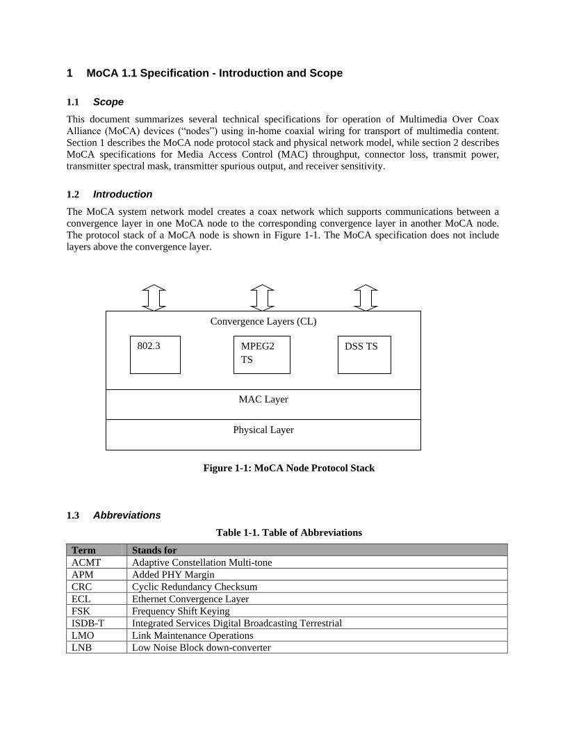
1.2 Introduction
The MoCA system network model creates a coax network which supports communications between a
convergence layer in one MoCA node to the corresponding convergence layer in another MoCA node.
The protocol stack of a MoCA node is shown in Figure 1-1. The MoCA specification does not include
layers above the convergence layer.
Figure 1-1: MoCA Node Protocol Stack
1.3 Abbreviations
Table 1-1. Table of Abbreviations
Term Stands for
ACMT Adaptive Constellation Multi-tone
APM Added PHY Margin
CRC Cyclic Redundancy Checksum
ECL Ethernet Convergence Layer
FSK Frequency Shift Keying
ISDB-T Integrated Services Digital Broadcasting Terrestrial
LMO Link Maintenance Operations
LNB Low Noise Block down-converter
Physical Layer
MAC Layer
Convergence Layers (CL)
MPEG2
TS
DSS TS 802.3
Page 5
MAC Media Access Control
MoCA Multimedia over Coax Alliance
OSP Operator-Service Provider
PHY Physical Layer
RBW Resolution Bandwidth
SWM Single Wire Multi-switch
VBW Video Bandwidth
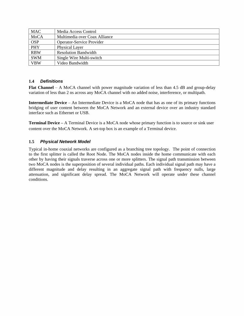
1.4 Definitions Flat Channel – A MoCA channel with power magnitude variation of less than 4.5 dB and group-delay
variation of less than 2 ns across any MoCA channel with no added noise, interference, or multipath.
Intermediate Device – An Intermediate Device is a MoCA node that has as one of its primary functions
bridging of user content between the MoCA Network and an external device over an industry standard
interface such as Ethernet or USB.
Terminal Device – A Terminal Device is a MoCA node whose primary function is to source or sink user
content over the MoCA Network. A set-top box is an example of a Terminal device.
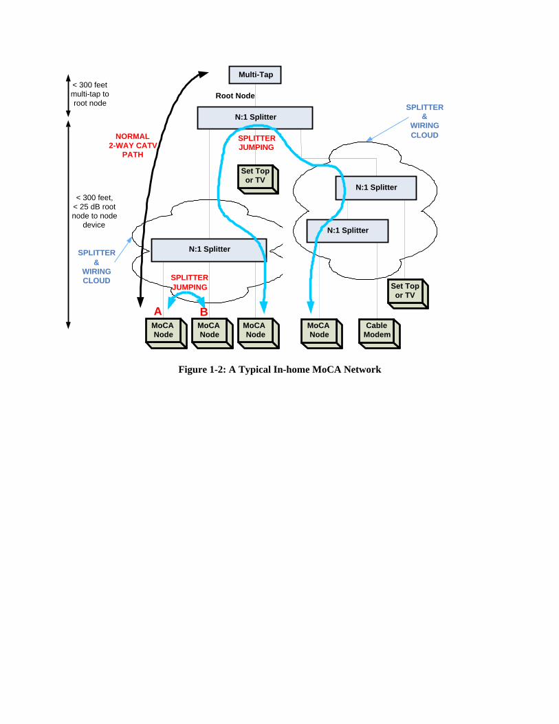
1.5 Physical Network Model
Typical in-home coaxial networks are configured as a branching tree topology. The point of connection
to the first splitter is called the Root Node. The MoCA nodes inside the home communicate with each
other by having their signals traverse across one or more splitters. The signal path transmission between
two MoCA nodes is the superposition of several individual paths. Each individual signal path may have a
different magnitude and delay resulting in an aggregate signal path with frequency nulls, large
attenuation, and significant delay spread. The MoCA Network will operate under these channel
conditions.
Page 6
Figure 1-2: A Typical In-home MoCA Network
N:1 Splitter
Set Top or TV
N:1 Splitter
Set Top or TV
Root Node
N:1 Splitter
MoCA Node
SPLITTER JUMPING
NORMAL 2-WAY CATV
PATH
N:1 Splitter
Cable Modem
SPLITTER &
WIRING CLOUD
SPLITTER &
WIRING CLOUD
A B
Multi-Tap < 300 feet multi-tap to root node
< 300 feet, < 25 dB root node to node
device
MoCA Node
MoCA Node
MoCA Node
SPLITTER JUMPING
Page 7
2 MoCA 1.1 Reference Specification
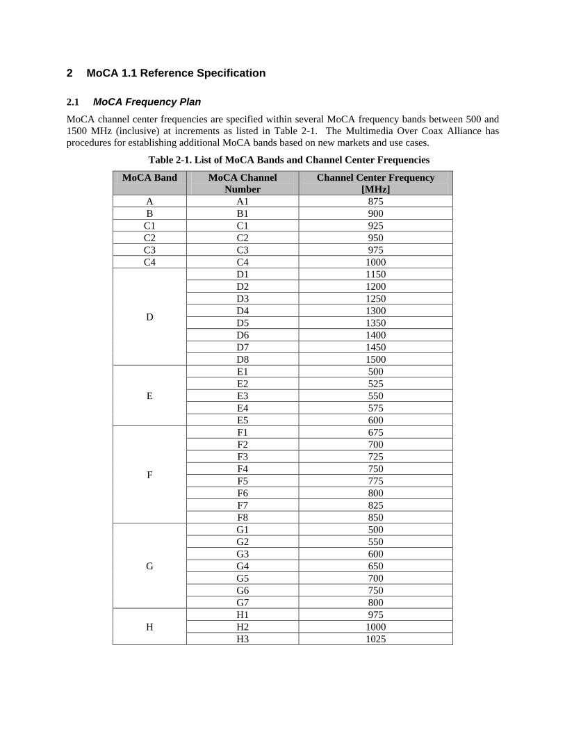
2.1 MoCA Frequency Plan
MoCA channel center frequencies are specified within several MoCA frequency bands between 500 and
1500 MHz (inclusive) at increments as listed in Table 2-1. The Multimedia Over Coax Alliance has
procedures for establishing additional MoCA bands based on new markets and use cases.
Table 2-1. List of MoCA Bands and Channel Center Frequencies
MoCA Band MoCA Channel
Number
Channel Center Frequency
[MHz]
A A1 875
B B1 900
C1 C1 925
C2 C2 950
C3 C3 975
C4 C4 1000
D
D1 1150
D2 1200
D3 1250
D4 1300
D5 1350
D6 1400
D7 1450
D8 1500
E
E1 500
E2 525
E3 550
E4 575
E5 600
F
F1 675
F2 700
F3 725
F4 750
F5 775
F6 800
F7 825
F8 850
G
G1 500
G2 550
G3 600
G4 650
G5 700
G6 750
G7 800
H
H1 975
H2 1000
H3 1025
Page 8
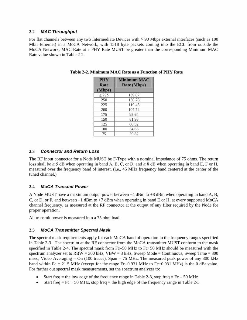
2.2 MAC Throughput
For flat channels between any two Intermediate Devices with > 90 Mbps external interfaces (such as 100
Mbit Ethernet) in a MoCA Network, with 1518 byte packets coming into the ECL from outside the
MoCA Network, MAC Rate at a PHY Rate MUST be greater than the corresponding Minimum MAC
Rate value shown in Table 2-2.
Table 2-2. Minimum MAC Rate as a Function of PHY Rate
PHY
Rate
(Mbps)
Minimum MAC
Rate (Mbps)
≥ 275 139.87
250 130.78 225 119.45 200 107.74 175 95.64 150 81.98 125 68.32 100 54.65 75 39.82
2.3 Connector and Return Loss
The RF input connector for a Node MUST be F-Type with a nominal impedance of 75 ohms. The return
loss shall be ≥ 5 dB when operating in band A, B, C, or D, and ≥ 8 dB when operating in band E, F or H,
measured over the frequency band of interest. (i.e., 45 MHz frequency band centered at the center of the
tuned channel.)
2.4 MoCA Transmit Power
A Node MUST have a maximum output power between 4 dBm to +8 dBm when operating in band A, B,
C, or D, or F, and between 1 dBm to +7 dBm when operating in band E or H, at every supported MoCA
channel frequency, as measured at the RF connector at the output of any filter required by the Node for
proper operation.
All transmit power is measured into a 75 ohm load.
2.5 MoCA Transmitter Spectral Mask
The spectral mask requirements apply for each MoCA band of operation in the frequency ranges specified
in Table 2-3. The spectrum at the RF connector from the MoCA transmitter MUST conform to the mask
specified in Table 2-4. The spectral mask from Fc50 MHz to Fc+50 MHz should be measured with the
spectrum analyzer set to RBW = 300 kHz, VBW = 3 kHz, Sweep Mode = Continuous, Sweep Time = 300
msec, Video Averaging = On (100 traces), Span = 75 MHz. The measured peak power of any 300 kHz
band within Fc 21.5 MHz (except for the range Fc0.931 MHz to Fc+0.931 MHz) is the 0 dBr value.
For farther out spectral mask measurements, set the spectrum analyzer to:
Start freq = the low edge of the frequency range in Table 2-3, stop freq = Fc – 50 MHz
Start freq = Fc + 50 MHz, stop freq = the high edge of the frequency range in Table 2-3
Page 9
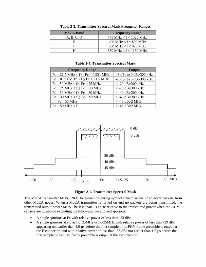
Table 2-3. Transmitter Spectral Mask Frequency Ranges
MoCA Band Frequency Range
A, B, C, D 775 MHz < f < 1525 MHz
E 400 MHz < f ≤ 800 MHz
F 600 MHz < f < 925 MHz
H 850 MHz < f < 1160 MHz
Table 2-4. Transmitter Spectral Mask
Frequency Range Output
Fc 21.5 MHz ≤ f < Fc 0.931 MHz 3 dBr to 0 dBr/300 kHz
Fc + 0.931 MHz < f ≤ Fc + 21.5 MHz 3 dBr to 0 dBr/300 kHz
Fc – 30 MHz ≤ f < Fc – 25 MHz < -20 dBr/300 kHz
Fc + 25 MHz < f ≤ Fc + 30 MHz < -20 dBr/300 kHz
Fc – 50 MHz ≤ f < Fc – 30 MHz < -40 dBr/300 kHz
Fc + 30 MHz < f ≤ Fc + 50 MHz < -40 dBr/300 kHz
f < Fc – 50 MHz < -45 dBr/2 MHz
Fc + 50 MHz < f < -45 dBr/2 MHz
Figure 2-1. Transmitter Spectral Mask
The MoCA transmitter MUST NOT be turned on during symbol transmissions of adjacent packets from
other MoCA nodes. When a MoCA transmitter is turned on and no packets are being transmitted, the
transmitted output power MUST be less than 39 dBc relative to the transmitted power when the ACMT
carriers are turned-on excluding the following two allowed spurious:
A single spurious at Fc with relative power of less than -23 dBc
A single spurious at either Fc+25MHz or Fc-25MHz with relative power of less than -39 dBc
appearing not earlier than 4.0 µs before the first sample of its PHY frame preamble is output at
the F-connector, and with relative power of less than -35 dBc not earlier than 1.5 µs before the
first sample of its PHY frame preamble is output at the F-connector.
25 21.5 30 50 -25 -30 - 50
0 dBr
-20 dBr
-40 dBr
-45 dBr
MHz Fc
-3 dBr
-21.5
Page 10
A MoCA transmitter SHOULD be turned on less than 7.4 µs before the first symbol has reached 90% of
its final value and SHOULD be turned off less than 1 µs after the last transmitted symbol.
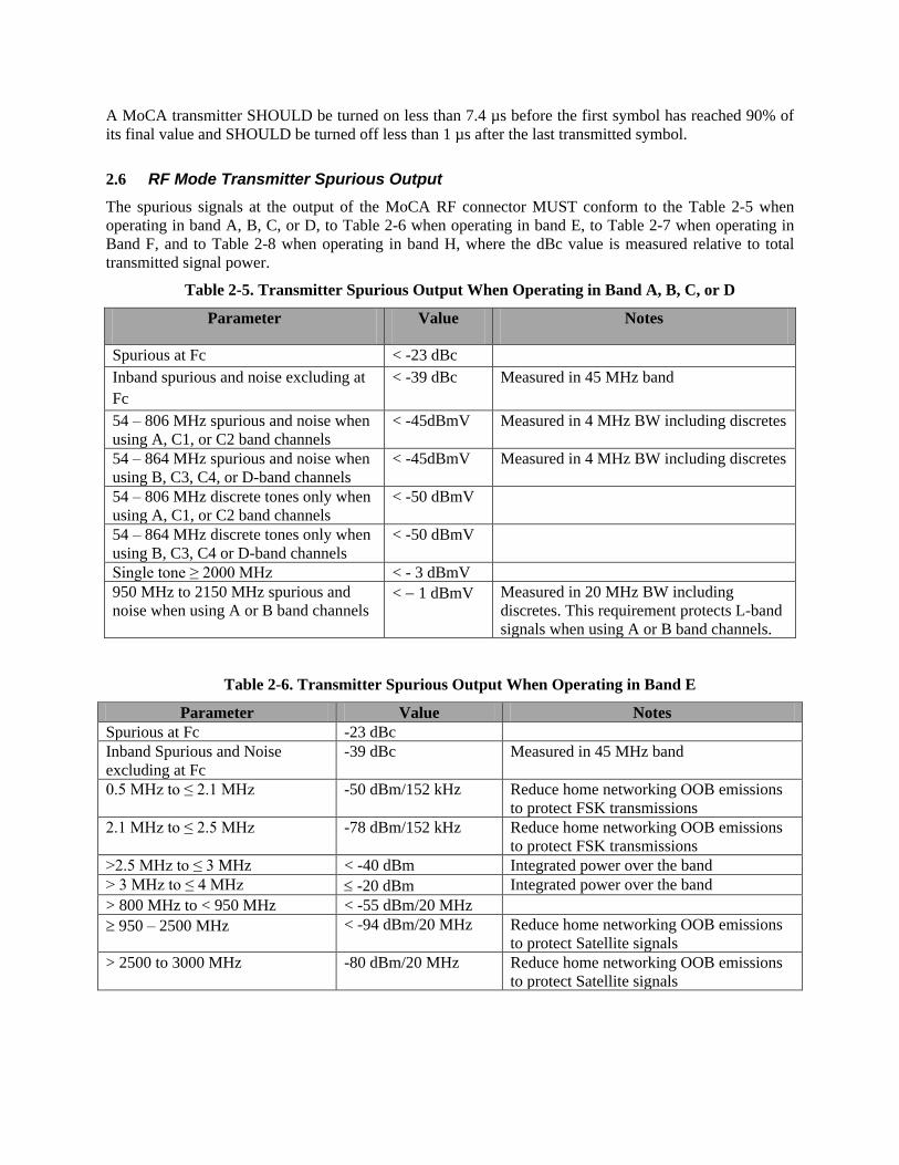
2.6 RF Mode Transmitter Spurious Output
The spurious signals at the output of the MoCA RF connector MUST conform to the Table 2-5 when
operating in band A, B, C, or D, to Table 2-6 when operating in band E, to Table 2-7 when operating in
Band F, and to Table 2-8 when operating in band H, where the dBc value is measured relative to total
transmitted signal power.
Table 2-5. Transmitter Spurious Output When Operating in Band A, B, C, or D
Parameter Value Notes
Spurious at Fc < -23 dBc
Inband spurious and noise excluding at
Fc
< -39 dBc Measured in 45 MHz band
54 – 806 MHz spurious and noise when
using A, C1, or C2 band channels
< -45dBmV Measured in 4 MHz BW including discretes
54 – 864 MHz spurious and noise when
using B, C3, C4, or D-band channels
< -45dBmV Measured in 4 MHz BW including discretes
54 – 806 MHz discrete tones only when
using A, C1, or C2 band channels
< -50 dBmV
54 – 864 MHz discrete tones only when
using B, C3, C4 or D-band channels
< -50 dBmV
Single tone ≥ 2000 MHz < - 3 dBmV
950 MHz to 2150 MHz spurious and
noise when using A or B band channels < 1 dBmV Measured in 20 MHz BW including
discretes. This requirement protects L-band
signals when using A or B band channels.
Table 2-6. Transmitter Spurious Output When Operating in Band E
Parameter Value Notes
Spurious at Fc -23 dBc
Inband Spurious and Noise
excluding at Fc
-39 dBc Measured in 45 MHz band
0.5 MHz to ≤ 2.1 MHz -50 dBm/152 kHz Reduce home networking OOB emissions
to protect FSK transmissions
2.1 MHz to ≤ 2.5 MHz -78 dBm/152 kHz Reduce home networking OOB emissions
to protect FSK transmissions
>2.5 MHz to ≤ 3 MHz < -40 dBm Integrated power over the band
> 3 MHz to ≤ 4 MHz -20 dBm Integrated power over the band
> 800 MHz to < 950 MHz < -55 dBm/20 MHz
950 – 2500 MHz < -94 dBm/20 MHz Reduce home networking OOB emissions
to protect Satellite signals
> 2500 to 3000 MHz -80 dBm/20 MHz Reduce home networking OOB emissions
to protect Satellite signals
Page 11
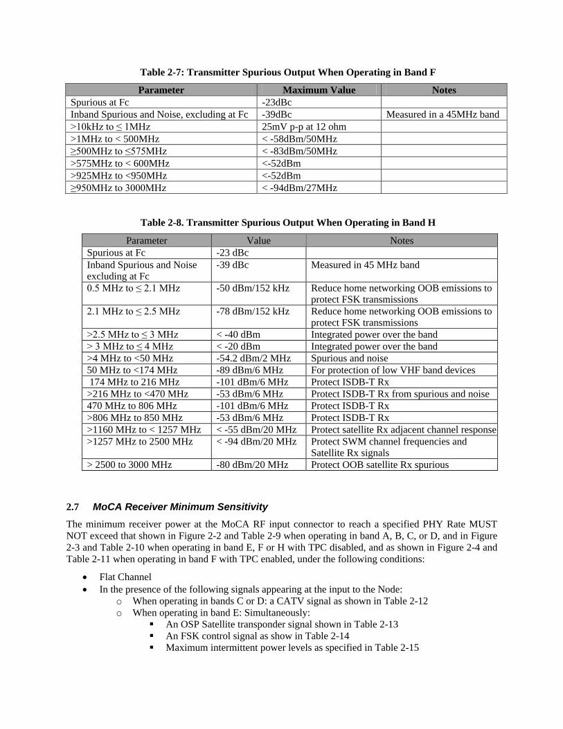
Table 2-7: Transmitter Spurious Output When Operating in Band F
Parameter Maximum Value Notes
Spurious at Fc -23dBc
Inband Spurious and Noise, excluding at Fc -39dBc Measured in a 45MHz band
>10kHz to ≤ 1MHz 25mV p-p at 12 ohm
>1MHz to < 500MHz < -58dBm/50MHz
≥500MHz to ≤575MHz < -83dBm/50MHz
>575MHz to < 600MHz <-52dBm
>925MHz to <950MHz <-52dBm
≥950MHz to 3000MHz < -94dBm/27MHz
Table 2-8. Transmitter Spurious Output When Operating in Band H
Parameter Value Notes
Spurious at Fc -23 dBc
Inband Spurious and Noise excluding at Fc
-39 dBc Measured in 45 MHz band
0.5 MHz to ≤ 2.1 MHz -50 dBm/152 kHz Reduce home networking OOB emissions to protect FSK transmissions
2.1 MHz to ≤ 2.5 MHz -78 dBm/152 kHz Reduce home networking OOB emissions to protect FSK transmissions
>2.5 MHz to ≤ 3 MHz < -40 dBm Integrated power over the band
> 3 MHz to ≤ 4 MHz < -20 dBm Integrated power over the band
>4 MHz to <50 MHz -54.2 dBm/2 MHz Spurious and noise
50 MHz to <174 MHz -89 dBm/6 MHz For protection of low VHF band devices
174 MHz to 216 MHz -101 dBm/6 MHz Protect ISDB-T Rx
>216 MHz to <470 MHz -53 dBm/6 MHz Protect ISDB-T Rx from spurious and noise
470 MHz to 806 MHz -101 dBm/6 MHz Protect ISDB-T Rx
>806 MHz to 850 MHz -53 dBm/6 MHz Protect ISDB-T Rx
>1160 MHz to < 1257 MHz < -55 dBm/20 MHz Protect satellite Rx adjacent channel response
>1257 MHz to 2500 MHz < -94 dBm/20 MHz Protect SWM channel frequencies and Satellite Rx signals
> 2500 to 3000 MHz -80 dBm/20 MHz Protect OOB satellite Rx spurious
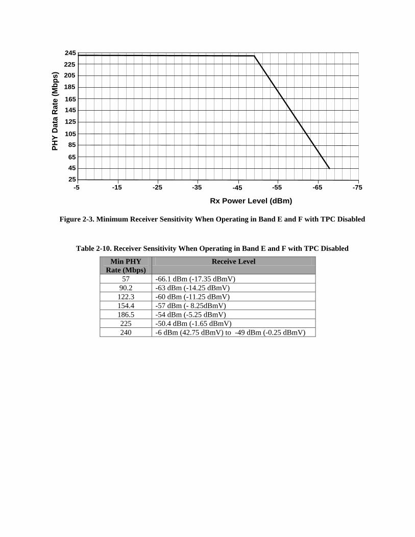
2.7 MoCA Receiver Minimum Sensitivity
The minimum receiver power at the MoCA RF input connector to reach a specified PHY Rate MUST
NOT exceed that shown in Figure 2-2 and Table 2-9 when operating in band A, B, C, or D, and in Figure
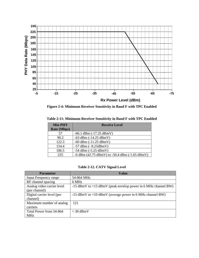
2-3 and Table 2-10 when operating in band E, F or H with TPC disabled, and as shown in Figure 2-4 and
Table 2-11 when operating in band F with TPC enabled, under the following conditions:
Flat Channel
In the presence of the following signals appearing at the input to the Node:
o When operating in bands C or D: a CATV signal as shown in Table 2-12
o When operating in band E: Simultaneously:
An OSP Satellite transponder signal shown in Table 2-13
An FSK control signal as show in Table 2-14
Maximum intermittent power levels as specified in Table 2-15
Page 12
o When operating in band F: Simultaneously:
OSP Satellite Transponder Signal Level as shown in Table 2-16
DiSEqC signal as show in
Page 13
Table 2-17
Maximum intermittent power levels as specified in Table 2-18
UHF Analog video signal as shown in Table 2-19
o When operating in band H: Simultaneously:
An ISDB-T signal shown in Table 2-20
An OSP Satellite transponder signal shown in Table 2-21
An FSK control signal as show in Table 2-14
Maximum intermittent power levels as specified in Table 2-22
No other External Interference
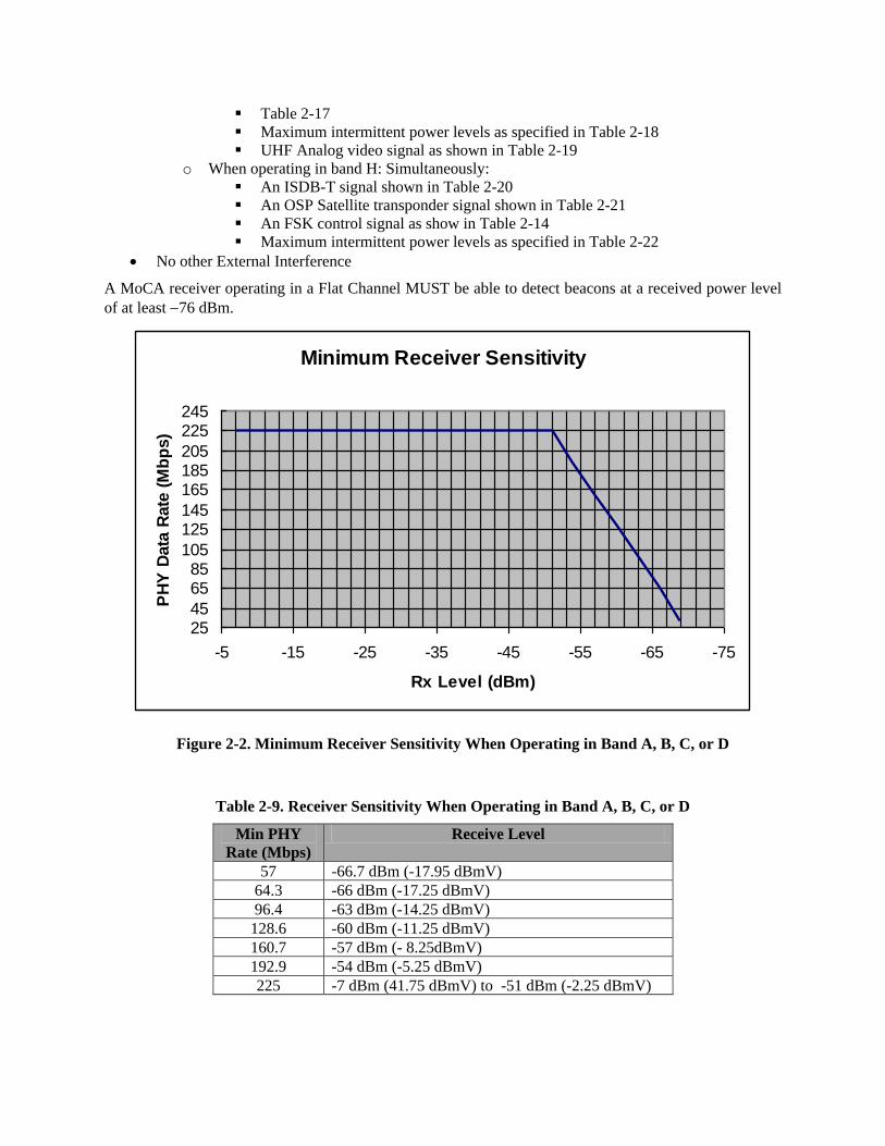
A MoCA receiver operating in a Flat Channel MUST be able to detect beacons at a received power level
of at least 76 dBm.
Figure 2-2. Minimum Receiver Sensitivity When Operating in Band A, B, C, or D
Table 2-9. Receiver Sensitivity When Operating in Band A, B, C, or D
Min PHY
Rate (Mbps)
Receive Level
57 -66.7 dBm (-17.95 dBmV)
64.3 -66 dBm (-17.25 dBmV)
96.4 -63 dBm (-14.25 dBmV)
128.6 -60 dBm (-11.25 dBmV)
160.7 -57 dBm (- 8.25dBmV)
192.9 -54 dBm (-5.25 dBmV)
225 -7 dBm (41.75 dBmV) to -51 dBm (-2.25 dBmV)
Minimum Receiver Sensitivity
2545
6585
105
125145
165185205
225245
-75-65-55-45-35-25-15-5
Rx Level (dBm)
PH
Y D
ata
Rate
(M
bp
s)
Page 14
-5
PH
Y D
ata
Ra
te (
Mb
ps
)
Rx Power Level (dBm)
45
65
85
105
125
145
165
185
205
225
245
-15 -25 -35 -45 -55 -65 -75
25
Figure 2-3. Minimum Receiver Sensitivity When Operating in Band E and F with TPC Disabled
Table 2-10. Receiver Sensitivity When Operating in Band E and F with TPC Disabled
Min PHY
Rate (Mbps)
Receive Level
57 -66.1 dBm (-17.35 dBmV)
90.2 -63 dBm (-14.25 dBmV)
122.3 -60 dBm (-11.25 dBmV)
154.4 -57 dBm (- 8.25dBmV)
186.5 -54 dBm (-5.25 dBmV)
225 -50.4 dBm (-1.65 dBmV)
240 -6 dBm (42.75 dBmV) to -49 dBm (-0.25 dBmV)
Page 15
25
-5
PH
Y D
ata
Ra
te (
Mb
ps
)
Rx Power Level (dBm)
45
65
85
105
125
145
165
185
205
225
245
-15 -25 -35 -45 -55 -65 -75
Figure 2-4: Minimum Receiver Sensitivity in Band F with TPC Enabled
Table 2-11: Minimum Receiver Sensitivity in Band F with TPC Enabled
Min PHY
Rate (Mbps)
Receive Level
57 -66.1 dBm (-17.35 dBmV)
90.2 -63 dBm (-14.25 dBmV)
122.3 -60 dBm (-11.25 dBmV)
154.4 -57 dBm (- 8.25dBmV)
186.5 -54 dBm (-5.25 dBmV)
225 -6 dBm (42.75 dBmV) to -50.4 dBm (-1.65 dBmV)
Table 2-12. CATV Signal Level
Parameter Value
Input Frequency range 54-864 MHz
RF channel spacing 6 MHz
Analog video carrier level
(per channel)
-15 dBmV to +15 dBmV (peak envelop power in 6 MHz channel BW)
Digital carrier level (per
channel)
-15 dBmV to +10 dBmV (average power in 6 MHz channel BW)
Maximum number of analog
carriers
121
Total Power from 54-864
MHz
< 30 dBmV
Page 16
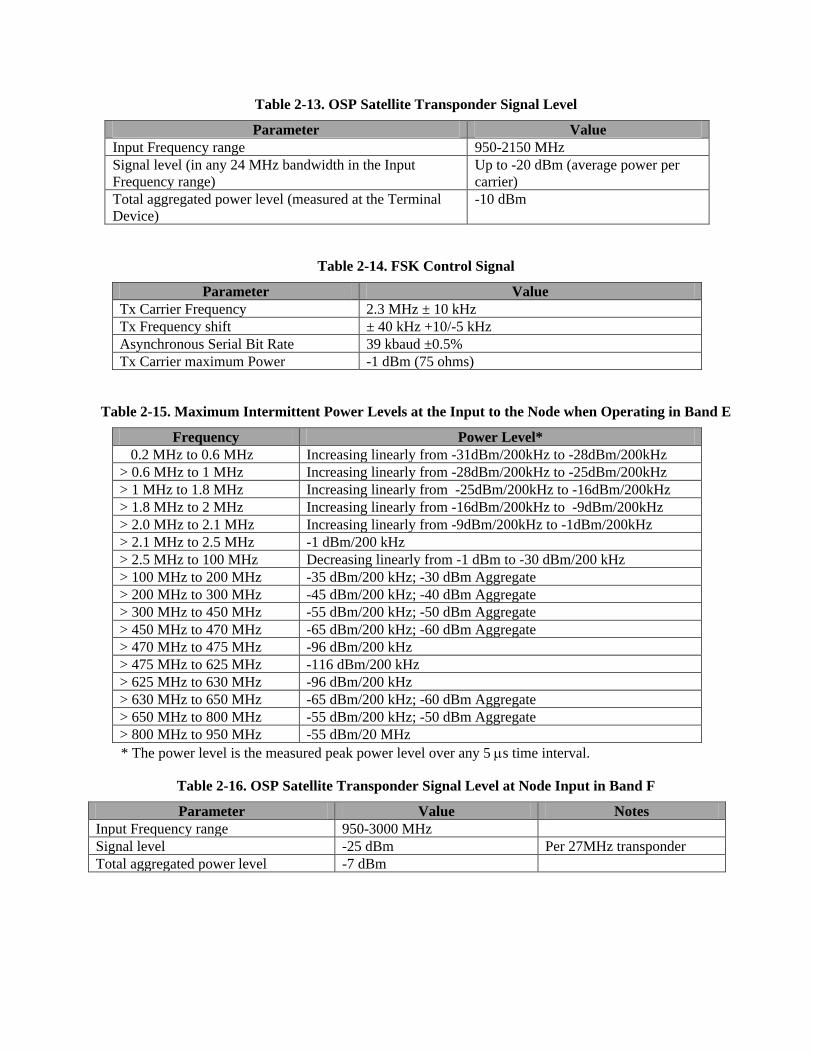
Table 2-13. OSP Satellite Transponder Signal Level
Parameter Value
Input Frequency range 950-2150 MHz
Signal level (in any 24 MHz bandwidth in the Input
Frequency range)
Up to -20 dBm (average power per
carrier)
Total aggregated power level (measured at the Terminal
Device)
-10 dBm
Table 2-14. FSK Control Signal
Parameter Value
Tx Carrier Frequency 2.3 MHz ± 10 kHz
Tx Frequency shift ± 40 kHz +10/-5 kHz
Asynchronous Serial Bit Rate 39 kbaud ±0.5%
Tx Carrier maximum Power -1 dBm (75 ohms)
Table 2-15. Maximum Intermittent Power Levels at the Input to the Node when Operating in Band E
Frequency Power Level*
0.2 MHz to 0.6 MHz Increasing linearly from -31dBm/200kHz to -28dBm/200kHz
> 0.6 MHz to 1 MHz Increasing linearly from -28dBm/200kHz to -25dBm/200kHz
> 1 MHz to 1.8 MHz Increasing linearly from -25dBm/200kHz to -16dBm/200kHz
> 1.8 MHz to 2 MHz Increasing linearly from -16dBm/200kHz to -9dBm/200kHz
> 2.0 MHz to 2.1 MHz Increasing linearly from -9dBm/200kHz to -1dBm/200kHz
> 2.1 MHz to 2.5 MHz -1 dBm/200 kHz
> 2.5 MHz to 100 MHz Decreasing linearly from -1 dBm to -30 dBm/200 kHz
> 100 MHz to 200 MHz -35 dBm/200 kHz; -30 dBm Aggregate
> 200 MHz to 300 MHz -45 dBm/200 kHz; -40 dBm Aggregate
> 300 MHz to 450 MHz -55 dBm/200 kHz; -50 dBm Aggregate
> 450 MHz to 470 MHz -65 dBm/200 kHz; -60 dBm Aggregate
> 470 MHz to 475 MHz -96 dBm/200 kHz
> 475 MHz to 625 MHz -116 dBm/200 kHz
> 625 MHz to 630 MHz -96 dBm/200 kHz
> 630 MHz to 650 MHz -65 dBm/200 kHz; -60 dBm Aggregate
> 650 MHz to 800 MHz -55 dBm/200 kHz; -50 dBm Aggregate
> 800 MHz to 950 MHz -55 dBm/20 MHz
* The power level is the measured peak power level over any 5 s time interval.
Table 2-16. OSP Satellite Transponder Signal Level at Node Input in Band F
Parameter Value Notes
Input Frequency range 950-3000 MHz
Signal level -25 dBm Per 27MHz transponder
Total aggregated power level -7 dBm
Page 17
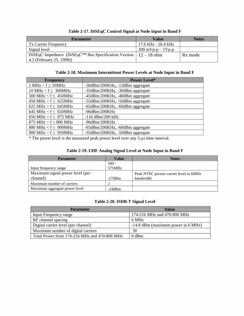
Table 2-17. DiSEqC Control Signal at Node Input in Band F
Parameter Value Notes
Tx Carrier Frequency 17.6 kHz - 26.4 kHz
Signal level 200 mVp-p – 1Vp-p
DiSEqC Impedance (DiSEqC™ Bus Specification Version
4.2 (February 25, 1998)) 12 – 18 ohm Rx mode
Table 2-18. Maximum Intermittent Power Levels at Node Input in Band F
Frequency Power Level*
1 MHz < f ≤ 10MHz -30dBm/200KHz, -13dBm aggregate
10 MHz < f ≤ 300MHz -35dBm/200KHz, -30dBm aggregate
300 MHz < f ≤ 450MHz -45dBm/200KHz, -40dBm aggregate
450 MHz < f ≤ 625MHz -55dBm/200KHz, -50dBm aggregate
625 MHz < f ≤ 645MHz -65dBm/200KHz, -60dBm aggregate
645 MHz < f ≤ 650MHz -96dBm/200KHz
650 MHz < f ≤ 875 MHz -116 dBm/200 kHz
875 MHz < f ≤ 880 MHz -96dBm/200KHz
880 MHz < f ≤ 900MHz -65dBm/200KHz, -60dBm aggregate
900 MHz < f ≤ 950MHz -55dBm/200KHz, -50dBm aggregate
* The power level is the measured peak power level over any 5 s time interval.
Table 2-19. UHF Analog Signal Level at Node Input in Band F
Parameter Value Notes
Input frequency range
500 -
575MHz
Maximum signal power level (per
channel) -27dBm
Peak NTSC picture carrier level in 6MHz
bandwidth
Maximum number of carriers 2
Maximum aggregate power level -24dBm
Table 2-20. ISDB-T Signal Level
Parameter Value Input Frequency range 174-216 MHz and 470-806 MHz
RF channel spacing 6 MHz
Digital carrier level (per channel) -14.8 dBm (maximum power in 6 MHz) channel) Maximum number of digital carriers 30
Total Power from 174-216 MHz and 470-806 MHz 0 dBm
Page 18
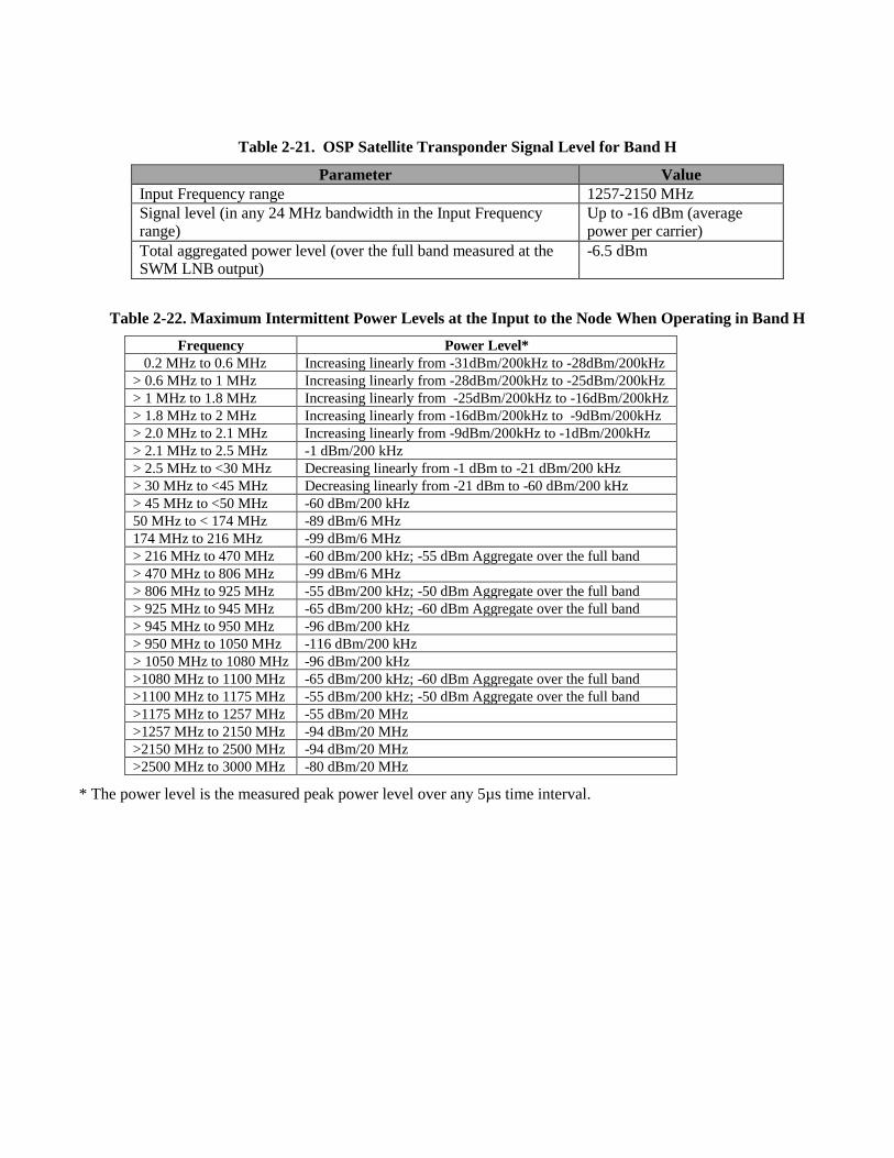
Table 2-21. OSP Satellite Transponder Signal Level for Band H
Parameter Value
Input Frequency range 1257-2150 MHz
Signal level (in any 24 MHz bandwidth in the Input Frequency range)
Up to -16 dBm (average power per carrier)
Total aggregated power level (over the full band measured at the SWM LNB output)
-6.5 dBm
Table 2-22. Maximum Intermittent Power Levels at the Input to the Node When Operating in Band H
Frequency Power Level*
0.2 MHz to 0.6 MHz Increasing linearly from -31dBm/200kHz to -28dBm/200kHz
> 0.6 MHz to 1 MHz Increasing linearly from -28dBm/200kHz to -25dBm/200kHz
> 1 MHz to 1.8 MHz Increasing linearly from -25dBm/200kHz to -16dBm/200kHz
> 1.8 MHz to 2 MHz Increasing linearly from -16dBm/200kHz to -9dBm/200kHz
> 2.0 MHz to 2.1 MHz Increasing linearly from -9dBm/200kHz to -1dBm/200kHz
> 2.1 MHz to 2.5 MHz -1 dBm/200 kHz
> 2.5 MHz to <30 MHz Decreasing linearly from -1 dBm to -21 dBm/200 kHz
> 30 MHz to <45 MHz Decreasing linearly from -21 dBm to -60 dBm/200 kHz
> 45 MHz to <50 MHz -60 dBm/200 kHz
50 MHz to < 174 MHz -89 dBm/6 MHz
174 MHz to 216 MHz -99 dBm/6 MHz
> 216 MHz to 470 MHz -60 dBm/200 kHz; -55 dBm Aggregate over the full band
> 470 MHz to 806 MHz -99 dBm/6 MHz
> 806 MHz to 925 MHz -55 dBm/200 kHz; -50 dBm Aggregate over the full band
> 925 MHz to 945 MHz -65 dBm/200 kHz; -60 dBm Aggregate over the full band
> 945 MHz to 950 MHz -96 dBm/200 kHz
> 950 MHz to 1050 MHz -116 dBm/200 kHz
> 1050 MHz to 1080 MHz -96 dBm/200 kHz
>1080 MHz to 1100 MHz -65 dBm/200 kHz; -60 dBm Aggregate over the full band
>1100 MHz to 1175 MHz -55 dBm/200 kHz; -50 dBm Aggregate over the full band
>1175 MHz to 1257 MHz -55 dBm/20 MHz
>1257 MHz to 2150 MHz -94 dBm/20 MHz
>2150 MHz to 2500 MHz -94 dBm/20 MHz
>2500 MHz to 3000 MHz -80 dBm/20 MHz
* The power level is the measured peak power level over any 5µs time interval.