, '-" '-'1" , •. - - - -- DOE/NASA/20320-69 NASA TM-87233 NASA- TM-87233 Mod-2 Wind Turbine Field Operations Experience Larry H. Gordon National Aeronautics and Space Administration Lewis Research Center December 1985 Prepared for U.S. DEPARTMENT OF ENERGY Conservation and Renewable Energy Wind/Ocean Technology Division IIUIIIII IIU IIII UIII IIUI IIIII UIU IIII lUI NF01503 https://ntrs.nasa.gov/search.jsp?R=19860009305 2018-06-13T11:15:17+00:00Z
Transcript
, '-" '-'1" , •. - - ~ - --
DOE/NASA/20320-69 NASA TM-87233 NASA-TM-87233
Mod-2 Wind Turbine Field Operations Experience
Larry H. Gordon National Aeronautics and Space Administration Lewis Research Center
December 1985
Prepared for
U.S. DEPARTMENT OF ENERGY Conservation and Renewable Energy Wind/Ocean Technology Division
Iq8?eo{J1.3o~
IIUIIIII IIU IIII UIII IIUI IIIII UIU IIII lUI NF01503
This report was prepared as an account of work sponsored by an agency of the United States Government. Neither the United States Government nor any agency thereof, nor any of their employees, makes any warranty, express or implied, or assumes any legal liability or responsibility for the accuracy, completeness, or usefulness of any information, apparatus, product, or process disclosed, or represents that its use would not infringe privately owned rights. Reference herein to any specific commercial product, process, or service by trade name, trademark, manufacturer, or otherwise, does not necessarily constitute or imply Its endorsement, recommendation, or favoring by the United States Government or any agency thereof. The views and opinions of authors expressed herein do not necessarily state or reflect those of the United States Government or any agency thereof.
Printed in the United States of America
Available from National Technical Information Service U.S. Department of Commerce 5285 Port Royal Road Springfield, VA 22161
1Codes are used for pricing all publications. The code is determined by the number of pages in the publication. Information pertaining to the pricing codes can be found in the current issues of the following publications, which are generally available in most libraries: Energy Research Abstracts (ERA); Government Reports Announcements and Index (GRA and I); Scientific and Technical Abstract Reports (STAR); and publication, NTIS-PR-360 available from NTIS at the above address.
Mod-2 Wind Turbine Field Operations Experience
Larry H. Gordon National Aeronautics and Space Administration Lewis Research Center Cleveland, Ohio 44135
Decem ber 1985
Work performed for u.s. DEPARTMENT OF ENERGY Conservation and Renewable Energy Wind/Ocean Technology Division Washington, D.C. 20545
DOE/NASA/20320-69 NASA TM-87233
Under Interagency Agreement DE-AI01-76ET20320
MOD-2WIND TURBINE FIELD OPERATIONS EXPERIENCE
Larry H. Gordon National Aeronautics and Space Administration
Lew1s Research Center Cleveland, Ohio 44135
SUMMARY
The Mod-2 wind turbine project 1s a development and research test operations program sponsored by the U.S. Department of Energy (Off1ce of Solar Electric Technolog1es), managed by the NASA Lewis Research Center. The development of the turb1ne was 1n1t1ated 1n 1977 under a contract NASA awarded to the Boeing Engineering Company (now Boeing Aerospace Co.). The three-machine, 7.5 MW Goodnoe Hills cluster, located near Goldendale, Washington, is now 1n a research/experimental operations phase that offers a unique opportunity to study the effects of s1ngle and mult1ple wind turbines 1nteract1ng with each other, the power grid; and the environment. Following a br1ef description of the turbine and project history, this paper addresses major problem areas and research and development test results. Field operations, both routine and nonrout1ne, are d1scussed. Rout1ne operation to date has produced over 13 379 000 KWh of electr1cal energy during 11 064 hr of rotation. Nonrout1ne operat1on includes suspended activities caused by a crack in the low speed shaft that necessitated a redesign and reinstallation of this assembly on all three turbines. With the world's largest cluster back in full operation, two of the turbines will be operated over the next several years to determ1ne their value as energy producers. The third unit w1l1 be used primarily for conduct-1ng research tests requ1r1ng conf1gurat1on changes to better understand the w1nd turbine technology. Technical areas summarized pertain to system performance and enhancements. Specific research tests relating to acoustics, TV interference, and wake effects conclude the paper.
SYSTEM DESCRIPTION
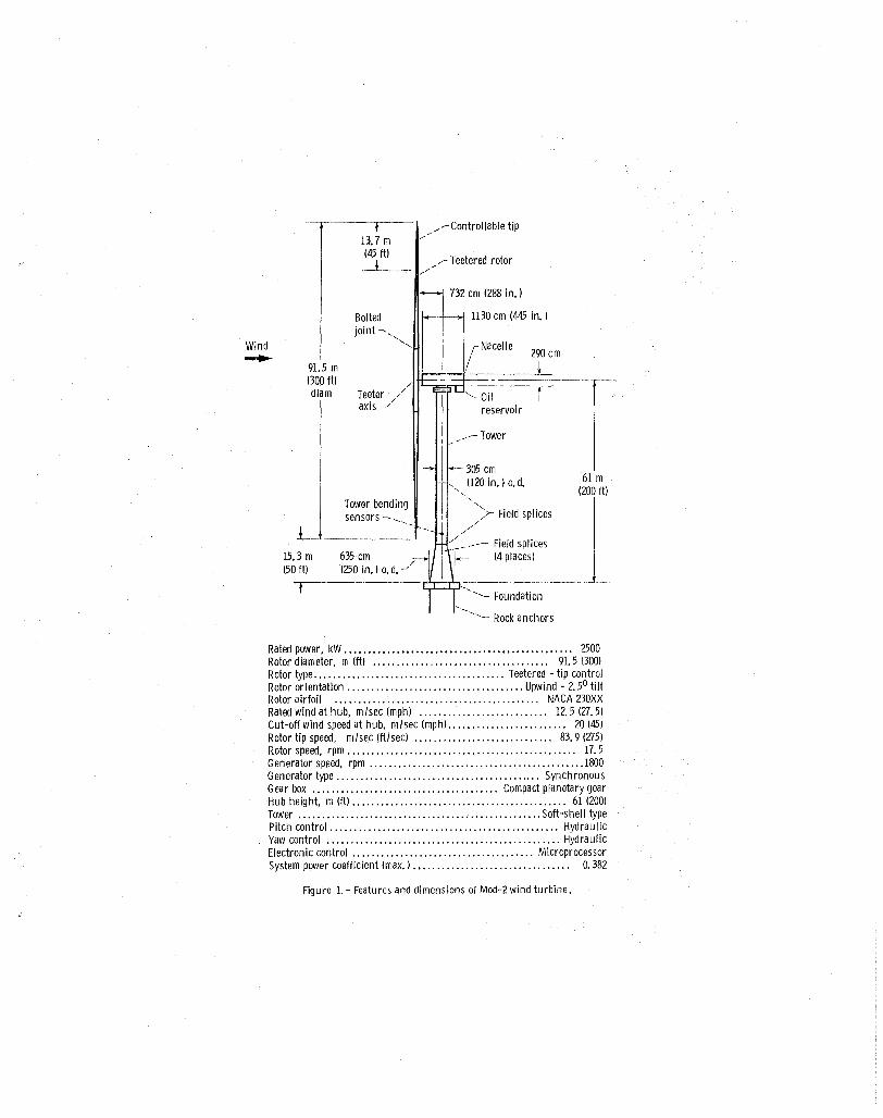
The Mod-2 wind turbine is a horizontal ax1s machine ut1l1z1ng a 300-ft diameter part1al span control, upw1nd rotor, as shown in figure 1.
The rotor's center of rotation is 200 feet above ground level. It is coupled to the low speed shaft through an elastomer1c teeter bearing. A 2500 kW synchronous generator is driven via a step-up planetary gearbox and "soft" quill shaft for torque transm1ss1on. The generator, gearbox, hydraulic systems, electronic controls and other support equipment are enclosed 1n a nacelle mounted atop a cylindrical steel tower. The nacelle can be yawed (rotated) to keep the rotor oriented correctly 1nto the wind as the wind direction changes. A hydrau11c p1tch control system is used to control the position of the movable rotor tips. The movable rotor tips are used to obtain a constant rotat1onal speed of 17.5 rpm and to maintain the proper power output at wind speeds above rated wind speed (27.5 mph at hub), and to provide for shutdown by feathering of the rotor t1ps (ref. 1).
The Mod-2 is controlled by an electronic microprocessor. The microprocessor 1s des1gned to allow unattended operat1on of the WTS at a remote site by mon1toring wind cond1tions and the operat1onal status of the wind turbine.
Equipment failures result in automatic safe shutdown of the WTS. The system status is monitored at the utility substation, from which maintenance crews are dispatched as needed.
PROJECT HISTORY
The u.S. Department of Energy (DOE) Office of Solar Electric Technologies has overall responsibility for conceiving and direct1ng research and development of w1nd energy systems. The DOE has delegated project management responsib1l1ty to the NASA Lew1s Research Center (LeRC), 1n Cleveland, Ohio, for the design fabrication, and field testing of large (100 kW and larger) horizontalaxis wind turbine systems (WTS) for utility applications. The ultimate objective of the Federal Wind Energy Program and the projects by which it is implemented is to develop the technology base necessary for private industry to generate cost effective wind-powered electricity.
The Mod-2 wind turbine project was initiated in 1977 for the design, installation, and research testing of an experimental wind turbine system under a contract with Boeing Engineering and Construction (now Boeing Aerospace Co.). Eventually, three turbine systems were erected at a single site near Goldendale, Washington to evaluate interactive and turbine/grid effects of multiple, identical, turbines integrated into a utility network. The first rotation of a Mod-2 turbine occurred in November 1980. The cluster was dedicated in May 1981 and final acceptance occurred in October 1982.
In November 1982, a generic failure of the low speed shafts in the Mod-2 turbines occurred necessitating redesign of the shaft (discussed later). In April 1985 the entire cluster was returned to service.
To date the Mod-2 cluster has generated 13.3 GWh while operating for 11 064 hr. Specific synchronous hours and energy produced by each turbine, as well as maximum periods of continuous/simultaneous operations, are noted in table I.
PROBLEM AREAS
Two major incidents have occurred during the course of this project: (1) overs peed failure on Turbine No.1 and (2) low speed shaft failure on turbine 1.
Overspeed Failure
On June 8, 1981, a planned emergency shutdown test of Turbine No.1 was initiated. A failure occurred in the Emergency Shutdown System (ESS) that can be summarized as follows:
1. While the machine was operating at a rated power of 2500 MW~ a failure shutdown was initiated by commanding the emergency shutdown system through the emergency stop button located on the manual control panel at the base of the tower.
2
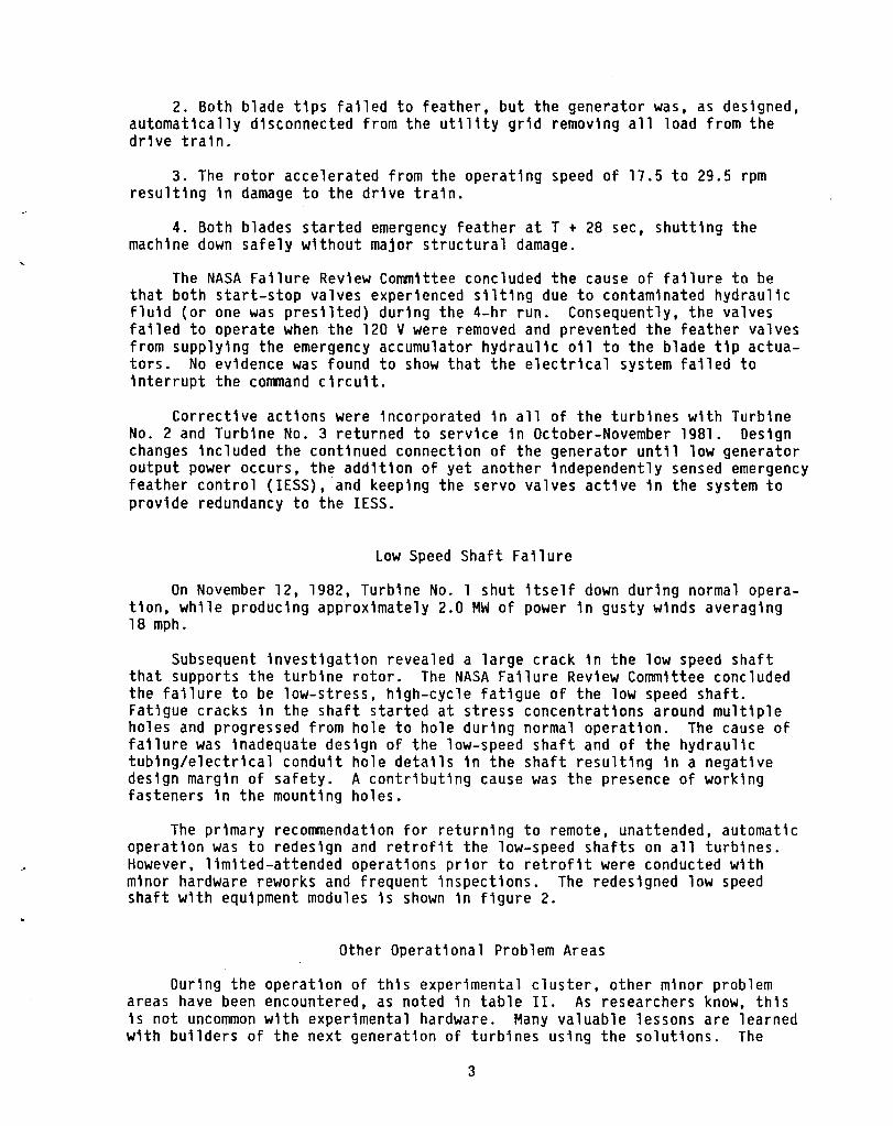
2. Both blade t1ps fa11ed to feather, but the generator was, as des1gned, automat1cally d1sconnected from the ut1l1ty grid remov1ng all load from the dr1ve tra1n.
3. The rotor accelerated from the operat1ng speed of 17.5 to 29.5 rpm resu1t1ng 1n damage to the dr1ve tra1n.
4. Both blades started emergency feather at T + 28 sec, shutt1ng the mach1ne down safely w1thout major structural damage.
The NASA fa11ure Rev1ew Comm1ttee concluded the cause of fa11ure to be that both start-stop valves exper1enced s11t1ng due to contam1nated hydrau11c f1u1d (or one was pres11ted) dur1ng the 4-hr run. Consequently, the valves fa11ed to operate when the 120 V were removed and prevented the feather valves from supp1y1ng the emergency accumulator hydrau11c 011 to the blade t1p actuators. No ev1dence was found to show that the e1ectr1ca1 system fa11ed to 1nterrupt the command c1rcu1t.
Correct1ve act10ns were 1ncorporated 1n all of the turbines w1th Turb1ne No.2 and Turb1ne No.3 returned to serv1ce 1n October-November 1981. Des1gn changes 1nc1uded the cont1nued connect10n of the generator unt11 low generator output power occurs, the add1t10n of yet another 1ndependent1y sensed emergency feather control (lESS), and keep1ng the servo valves act1ve 1n the system to prov1de redundancy to the lESS.
Low Speed Shaft fa11ure
On November 12, 1982, Turb1ne No.1 shut 1tse1f down dur1ng normal operat1on, wh11e produc1ng app~oximate1y 2.0 MW of power 1n gusty w1nds averag1ng 18 mph.
Subsequent 1nvest1gat10n revealed a large crack 1n the low speed shaft that supports the turb1ne rotor. The NASA fa11ure Rev1ew Comm1ttee concluded the fa11ure to be low-stress, h1gh-cyc1e fat1gue of the low speed shaft. fat1gue cracks 1n the shaft started at stress concentrat1ons around mu1t1p1e holes and progressed from hole to hole dur1ng normal operat10n. The cause of failure was 1nadequate des1gn of the low-speed shaft and of the hydraulic tub1ng/e1ectr1ca1 conduit hole deta11s 1n the shaft resu1t1ng 1n a negat1ve des1gn marg1n of safety. A contr1but1ng cause was the presence of work1ng fasteners 1n the mount1ng holes.
The pr1mary recommendat10n for return1ng to remote, unattended, automat1c operat10n was to redesign and retrofit the low-speed shafts on all turb1nes. However, 11m1ted-attended operat10ns pr10r to retrof1t were conducted with minor hardware reworks and frequent 1nspect10ns. The redes1gned low speed shaft w1th equipment modules is shown in figure 2.
other Operat1ona1 Problem Areas
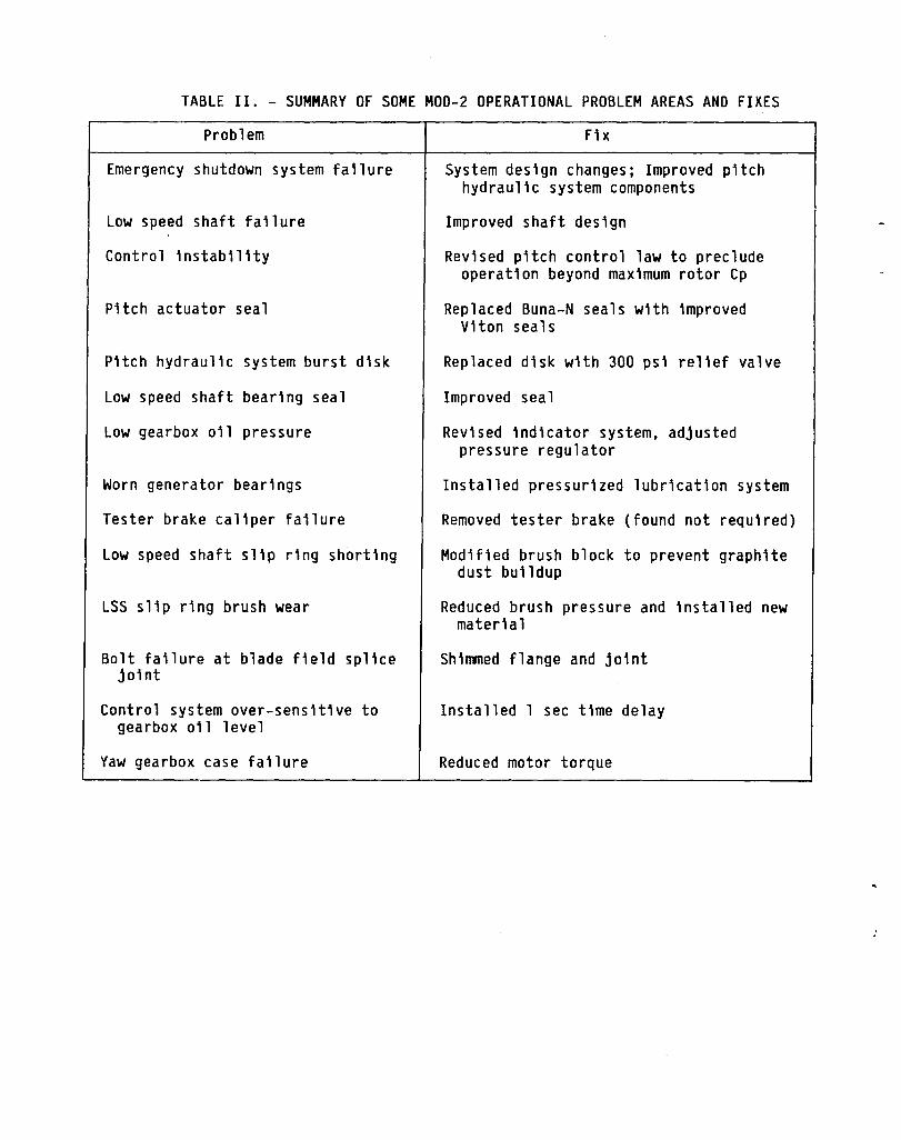
During the operat10n of this exper1menta1 cluster, other m1nor problem areas have been encountered, as noted 1n table II. As researchers know, this 1s not uncommon w1th exper1menta1 hardware. Many valuable lessons are learned w1th builders of the next generation of turbines us1ng the solut10ns. The
3
fixes noted in table II have been incorporated on the Mod-2 turbines and have also been factored into the design of the Mod-5 wind turbine - the third generation of large, multimegawatt wind turbines.
RESEARCH AND TECHNOLOGHY DEVELOPMENT TESTING
As previously noted, NASA researchers installed three Mod-2 turbines at a single site to test and evaluate interactive and machine/grid effects of multiple, identical turbines integrated into a utility network. Specifically, this research testing has been structured initially to emphasize three test project areas.
These tests are being conducted under the auspices of a Test Project Review Board with lead participation from Boeing Aerospace Co. (BAC), Bonneville Power Administration (BPA), Pacific Northwest Laboratory (PNL), Solar Energy Research Institute (SERI), described in reference 2.
To make the most of the research opportunities afforded by the Mod-2 turbines and site, NASA designers assigned the turbines separate primary test functions, while the turbines were still working as part of an energy producing, multi-unit cluster. As shown in figure 3, Turbines No.1 and 3 are dedicated to full, continuous operation in available winds with a goal of achieving 5000 to 10 000 hr of operating time on either or both turbines in CY 85/86. Turbine No.2 is the machine where advanced research will be first tested to develop large wind turbine technology further. Hence, configuration changes will be made only on this turbine.
Performance
Baseline. - The power variation with wind speed for Unit No.2 is shown in figure 4. This is typical for the three Mod-2 units at Goldendale, Washington. The power shown in figure 4 was measured at the generator output term1nals and the wind speed was measured at the 195-ft-level of the BPA meterological tower on the site.
Computer analysis reduced the data from the magnetic tape recordings. Each data point represents an average value for a 10-min interval, selected by searching the real time, brush recorder charts from the site. For operation below rated power, the pitch angle throughout the entire time interval was either +3 or +5°. To minimize data scatter, NASA and Boeing researchers selected intervals where the wind was reasonably smooth. The total variation in power during any time interval was usually less than 500 kW.
Enhancement. - In the Summer of 1983, researchers conducted a powerconversion enhancement research test using vortex generators on the blades. These small tabs, bonded to the rotor as shown in figure 5, are quite similar to those used on aircraft wings to improve performance. As summarized by reference 3 and shown in figure 6, the performance enhancement test results indicated that the addition of vortex generators (VGs) to the Mod-2 rotor
4
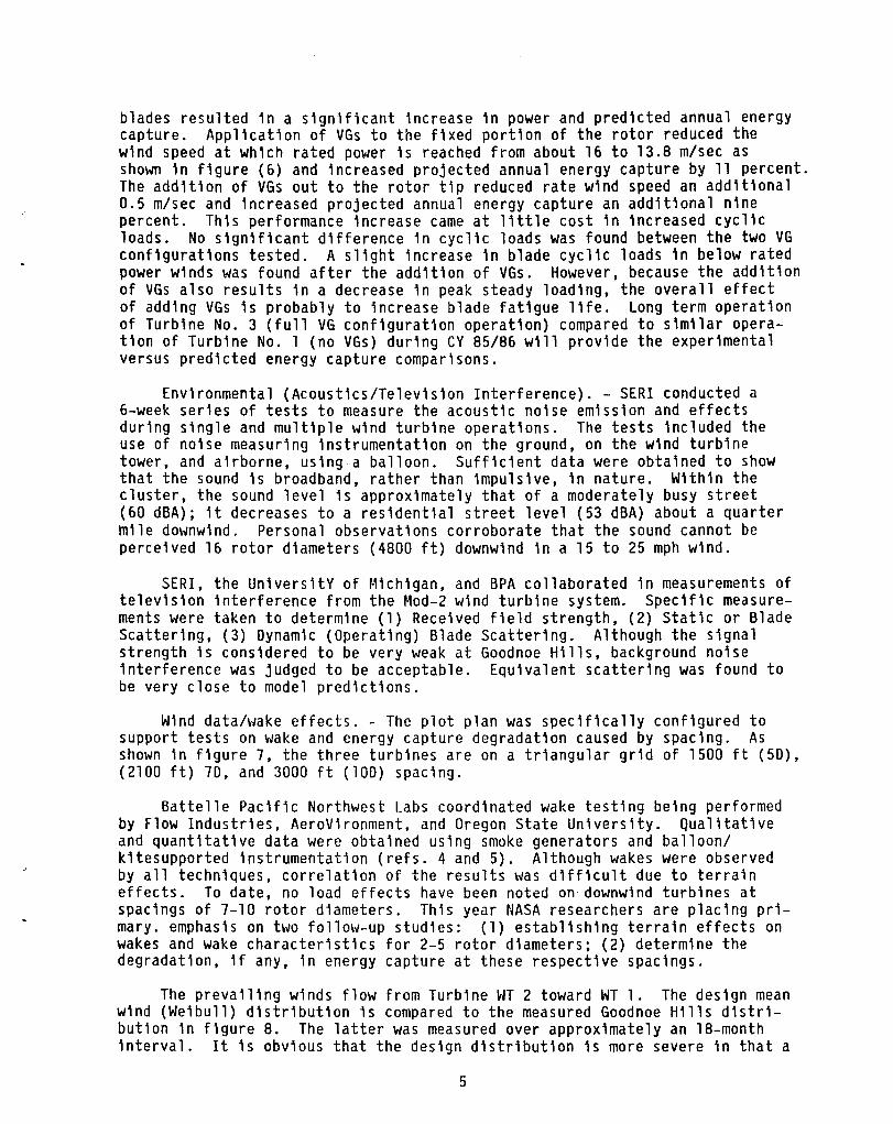
blades resulted 1n a s1gn1ficant increase in power and pred1cted annual energy capture. Application of VGs to the fixed portion of the rotor reduced the wind speed at which rated power is reached from about 16 to 13.8 m/sec as shown in f1gure (6) and increased projected annual energy capture by '1 percent. The addition of VGs out to the rotor tip reduced rate wind speed an additional 0.5 m/sec and 1ncreased projected annual energy capture an additional nine percent. This performance increase came at little cost in increased cyclic loads. No significant difference in cyclic loads was found between the two VG configurations tested. A slight increase in blade cyclic loads 1n below rated power w1nds was found after the addition of VGs. However, because the addition of VGs also results in a decrease in peak steady 10ad1ng, the overall effect of adding VGs is probably to increase blade fatigue life. Long term operation of Turbine No.3 (full VG configuration operat10n) compared to similar operation of Turbine No. 1 (no VGs) during CY 85/86 will provide the experimental versus predicted energy capture comparisons.
Environmental (Acoustics/Television Interference). - SERI conducted a 6-week series of tests to measure the acoustic noise emission and effects during single and multiple wind turbine operations. The tests included the use of n01se measuring instrumentation on the ground, on the wind turbine tower, and airborne, using a balloon. Sufficient data were obtained to show that the sound is broadband, rather than impulsive, in nature. Within the cluster, the sound level is approximately that of a moderately busy street (60 dBA); it decreases to a residential street level (53 dBA) about a quarter mile downwind. Personal observations corroborate that the sound cannot be perceived 16 rotor diameters (4800 ft) downwind in a 15 to 25 mph wind.
SERI, the University of Michigan, and BPA collaborated in measurements of television interference from the Mod-2 wind turbine system. Specific measurements were taken to determine (1) Received field strength, (2) Static or Blade Scattering, (3) Dynamic (Operating) Blade Scattering. Although the s1gnal strength is cons1dered to be very weak at Goodnoe Hills, background noise 1nterference was judged to be acceptable. Equ1valent scattering was found to be very close to model predictions.
Wind data/wake effects. - The plot plan was specifically configured to support tests on wake and energy capture degradation caused by spacing. As shown in figure 7, the three turbines are on a triangular grid of '500 ft (50), (2100 ft) 70, and 3000 ft (100) spacing.
Battelle Pacific Northwest Labs coordinated wake testing being performed by Flow Industries, AeroVironment, and Oregon State University. Qualitative and quantitative data were obtained using smoke generators and balloon/ k1tesupported 1nstrumentation (refs. 4 and 5). Although wakes were observed by all techniques, correlation of the results was difficult due to terrain effects. To date, no load effects have been noted on downwind turbines at spacings of 7-10 rotor diameters. This year NASA researchers are placing primary. emphasis on two follow-up studies: (1) establishing terrain effects on wakes and wake characteristics for 2-5 rotor diameters; (2) determine the degradation, if any, in energy capture at these respective spacings.
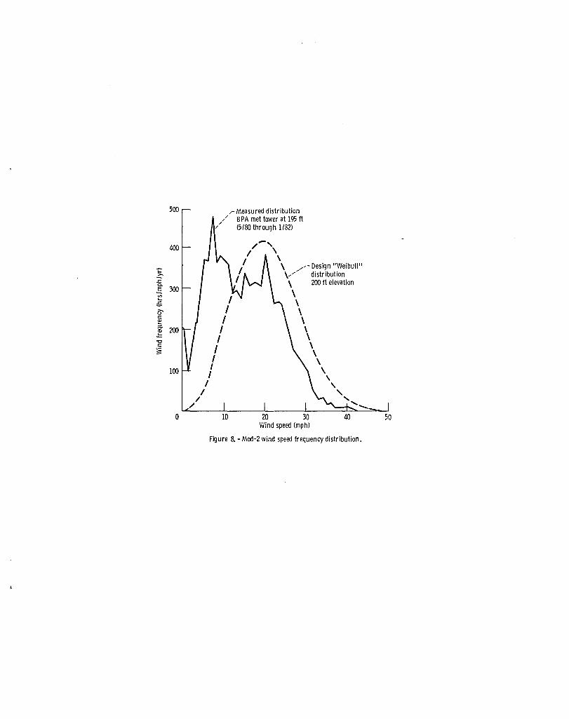
The prevai11ng winds flow from Turbine WT 2 toward WT 1. The design mean w1nd (Weibull) distribution is compared to the measured Goodnoe Hills distribution in figure 8. The latter was measured over approximately an 18-month interval. It is obvious that the design distribution is more severe in that a
5
larger percentage of time is spent at the higher wind speeds. Hence, the site winds are forgiving regarding turbine life but unfulfilling with regards to annual energy capture.
REFERENCES
1. Mod-2 Wind Turbine System Development. Volumes 1 and 2, NASA CR-168006 and NASA CR-168007, 1982.
2. Gordon, l.H.: Mod-2 Wind Turbine System Cluster Research Test Program. NASA TM-82906, 1982.
3. Sullivan, T.l.: Effect of Vortex Generators on the Power Conversion Performance and Structural Dynamic loads of the Mod-2 Wind Turbine. NASA TM-83680, 1984.
4. Baker, R.W.; and Walker, S.N.: Wake Studies at the Goodnoe Hills Mod-2 Site. DOE/BP-182, Oct. 1982.
5. lissaman, P.B.S.; Zambrano, T.B.; and Gyatt, G.W.: Wake Structure Measurements at the Mod-2 Cluster Test Facility at Goodnoe Hills. PNl-4572, Pacific Northwest laboratory, Mar. 1983.
6
TABLE I. -GOODNOE HILLS OPERATING SUMMARY (AS OF DEC. 31, 1985)
Turblne 1 Turblne 2 Turblne 3 Cluster
Hours of operatlon 3276 3165 4623 11 064 Hours of generatlon 3061 2964 4296 10 321 Energy generated, MWh 3871 3821 5687 ,13 379 Average power, kW 1265 1289 1324 1 296 Maxlmum cont1nuous run
tlme, hr 51 59 36 ------Max1mum s1multaneous
run t1me, hr, for -Two unHs 37 37 ---- ------Three unHs 18 18 18 ------
TABLE II. - SUMMARY OF SOME MOD-2 OPERATIONAL PROBLEM AREAS AND FIXES
Problem
Emergency shutdown system fallure
Low speed shaft fallure
Control lnstabl1lty
Pltch actuator seal
Pltch hydraullc system burst disk
Low speed shaft bearing seal
Low gearbox 011 pressure
Worn generator bearings
Tester brake callper fal1ure
Low speed shaft sllp ring shortlng
LSS sllp rlng brush wear
Bolt failure at blade field splice joint
Control system over-sensltive to gearbox 011 level
Yaw gearbox case failure
Flx
System design changes; Improved pitch hydraulic system components
Improved shaft design
Revlsed pitch control law to preclude operation beyond maximum rotor Cp
Modlfled brush block to prevent graphlte dust bul1dup
Reduced brush pressure and lnstalled new materlal
Shimmed flange and joint
Installed 1 sec tlme delay
Reduced motor torque
Wind .....
13. 7 m (45 tt)
t
Bolted joint --,
'-....,-
//
./-Controllable tip
// ___ Teetered rotor
91.5 m (300 ft) diam Teeter / / I~.....-I ====~----r
. / aXIs .J
Tower bending sensors ~ ___ _
-1,........-'-----_
15.3 m (50 ft)
635 cm (250 in. ) o. d. _/
reservoir
, m '-, (200 ft) , 1 '>- Field splices
/ //
/~_-- Field splices I (4 places) ___ _
"''- Foundation
'---- Rock anchors
Rated power, kW................................................ 2500 Rotor diameter, rn (ft) ••...•.••.••.•..•.•..•.••....•.••••.• 91. 5 (300) Rotor type ........................................ Teetered'" tip control Rotor orientation .... , ................................ Upwind - 2.50 tilt Rotor airfoil ...................... , .... .... . ... ..... ... NACA 230XX Rated wind at hub, m /sec (mph) ........................... 12.5 (27.5) Cut-off wind speed at hub, m/sec (mph) ......................... 20 (45) Rotor tip speed, m/sec (ft/sec) ............................. 83.9(275) Rotor speed, rpm................................................ 17.5 Generator speed, rpm ............................................. 1800 Generator type ........................................... Synchronous Gear box ....................................... Compact planetary gear Hub height. rn (ft) ............................................. 61 (200) Tower ................................................... Soft-shell type Pitch control ................................................ Hydraulic Yaw control ................................................. Hydraulic Electronic control ...................................... Microprocessor System power coefficient (max. ) . • • . . . . . . . . . . . . . . . . . . . . . . . . . . . . . . O. 382
Figure 1. - Featur!)s and dimensions of Mod-2 wind turbine.
, ' , ',- Decreased
number of shaft penetrations
Forward bearing bearing to shaft support increased
Figure 2. - Mod-2 redesigned low speed shaft.
coupling
/- Equ ipment / mountinq
modules
Figure 30 - Mod-2 wi nd turbi ne cluster test site at Goldendale, Washi ngton.
3.0
2.5
- 2.0
~ ... Q)
~ i 1.5 -ro ... Q)
c Q)
<.:l 1.0 -
.5 -
Standard sea level conditions averaging interval = 1. 0 min.
15
"-"
"-'- Prediction
(Pitch = + 3°)
20 25 30 35 40 Indicated wind speed at BPA met tower at 195 ft (mph)
Figure 4. - Performance curve for Mod-2 (turbine 2).
Figure 5. - Vortex generators.
o
45 50
2500
2000
:s: -"" ..... 1500 Q)
~ .... .s E ~ 1000 Q)
<.::>
500
Figure 6. - Comparison of performance data curve fits from 30rtex generator tests. Site standard conditions: air density, = 1.127 kg/m •
Units
WTl to WT2 WT2 to wn WT3 to WTl
A. PNL tower
Spacing, rotor diam
7 5
10
Figure 7. - Mod-2 cluster layout.
500 r Measured distribution / BPA met tower al195 It /
/ / (5/80 through 1182)
400
/~ Design "Weibull" ... \// distribution ..::-.c \ 200 It elevation Cl.
!: 300 \ '" I ... \ 5
~ I \ c: I \ Q.)
::J <:T 200 I \ Q.)
.l:: I \ "C
\ c: I ~ \ I \
100 I \ I \ / ,
/ " / " ./ ..... -0 10 20 30 40 50
Wind speed (mph)
Figure 8. - Mod-2 wind speed frequency distribution.
1. Report No. 2. Government Accession No.
NASA TM-87233 4. Title and Subtitle
Mod-2 W1nd Turb1ne F1e1d Operat1ons Exper1ence
7. Author(s)
Larry H. Gordon
9. Performing Organization Name and Address
Nat10nal Aeronaut1cs and Space Adm1n1strat1on Lew1s Research Center Cleveland, Oh10 44135
12. Sponsoring Agency Name and Address
U.S. Department of Energy W1nd/Ocean Technology D1v1s1on Wash1ngton, D.C. 20545
15. Supplementary Notes
3. Recipient's Catalog No.
5. Report Date
December 1985
6. Performing Organization Code
176-33-41 8. Performing Organization Report No.
E-2901
10. Work Unit No.
11. Contract or Grant No.
13. Type of Report and Period Covered
Techn1cal Memorandum
14. Sponsoring Agency C9deReport No.
DOE/NASA/20320-69
F1nal Report. Prepared under Interagency Agreement DE-AIOl-76ET20320.
16. Abstract
The Hod-2 wind turbine project is a development and research test operations program sponsored by the U.S. Department of Energy (Office of Solar Electric Technologies), managed by the NASA Lewis Research center; The development of the turbine was initiated in 1977 under a contract awarded by NASA to the Boeing Engineering Company (now Boeing Aerospace Co.). The three4nachine, 7.5 HW Goodnoe Hills cluster, located near Goldendale, Washington, is now in a research/experimental operations phase that offers a unique opportunity to study the effects of single and multiple wind turbines interacting with each other, the power grid; and the environment. Following a brief description of the turbine and project history, this paper addresses major problem areas and research and development test results. Field operations, both routine and nonroutine, are discussed. Routine operation to date has produced over 13 379 000 KWh of electrical energy during 11 064 hr of rotation. Nonroutine operation includes suspended activities caused by a crack in the low speed shaft that necessitated a redesign and reinstallation of this assembly on all three turbines. With the world's largest cluster back in full operation, two of the turbines will be operated over the next several years to detennine their value as energy producers. The third unit will be used primarily for conducting research tests requiring configuration changes to better understand the wind turbine technology. Technical areas summarized pertain to system performance and enhancements. Specific research tests relating to acoustics, TV interference, and wake effects conclude the paper.
17. Key Words (Suggested by Author(s))
W1nd energy; W1nd turb1ne
19. Security Classi!. (of this report)
Unclassified
18. Distribution Statement
Unclass1f1ed - un11m1ted STAR Category 44 DOE Category UC-60
20. Security Classif. (of this page)
Unclassif1ed 21. No. of pages
• For sale by the National Technical Information Service, Springfield, Virginia 22161