12
MODULE 7 MAINTENANCE PRACTICE 7.1 SAFE TY PRECAUTION
| Date post: | 05-Jul-2018 |
| Category: |
Documents |
| Upload: | syahirazaihad |
| View: | 260 times |
| Download: | 0 times |
8/16/2019 MOD 7 CAT B1.1(1)
http://slidepdf.com/reader/full/mod-7-cat-b111 1/12
MODULE 7 MAINTENANCE PRACTICE
7.1 SAFETY PRECAUTION

8/16/2019 MOD 7 CAT B1.1(1)
http://slidepdf.com/reader/full/mod-7-cat-b111 2/12
CAT B1.1
ANSWER ALL QUESTIONS
7.1.1 High-Pressure Gases
1. Compressed gases are frequently used in the maintenance and servicing of aircraft.
The use of compressed gases requires a special set of safety measures.
Q1: State safety rules apply fo r the use of com pressed g ases:

8/16/2019 MOD 7 CAT B1.1(1)
http://slidepdf.com/reader/full/mod-7-cat-b111 3/12
7.2.1.1 General Notes on Calibration
2. The scope of the records maintained, are dependent upon the standards required and
the nature of the equipment. The record system can also provide a valuable reference
in case of dispute or warranty claims. These records can also indicate ‘drift’ and canhelp in reassessing calibration intervals.
Q2: L is t a min imum in format ion content of any appl iance Cal ib rat ion Record o r
Cert if icate
8/16/2019 MOD 7 CAT B1.1(1)
http://slidepdf.com/reader/full/mod-7-cat-b111 4/12
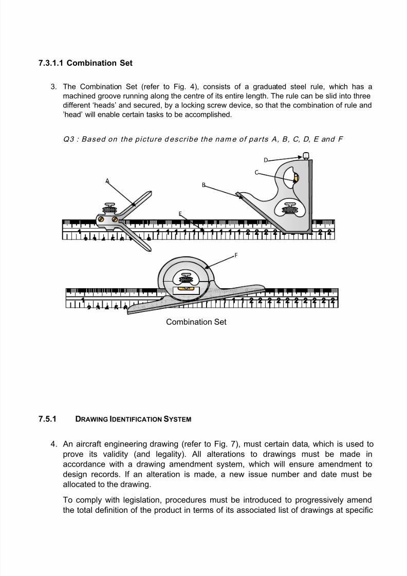
7.3.1.1 Combination Set
3. The Combination Set (refer to Fig. 4), consists of a graduated steel rule, which has a
machined groove running along the centre of its entire length. The rule can be slid into three
different ‘heads’ and secured, by a locking screw device, so that the combination of rule and
’head’ will enable certain tasks to be accomplished.
Q3 : Based on the picture d escribe the name of parts A, B, C, D, E and F
7.5.1 DRAWING IDENTIFICATION S YSTEM
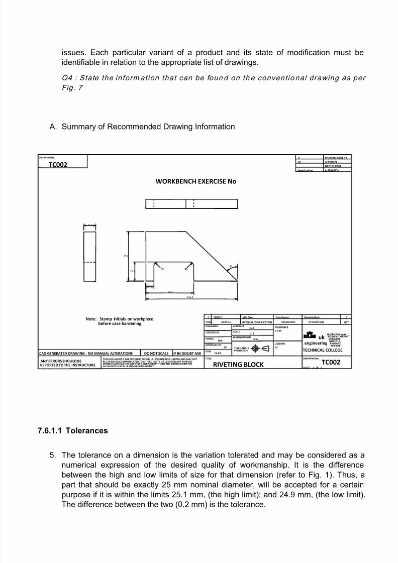
4. An aircraft engineering drawing (refer to Fig. 7), must certain data, which is used to
prove its validity (and legality). All alterations to drawings must be made in
accordance with a drawing amendment system, which will ensure amendment to
design records. If an alteration is made, a new issue number and date must be
allocated to the drawing.
To comply with legislation, procedures must be introduced to progressively amend
the total definition of the product in terms of its associated list of drawings at specific
Combination Set
AB
D
C
E
F
8/16/2019 MOD 7 CAT B1.1(1)
http://slidepdf.com/reader/full/mod-7-cat-b111 5/12
issues. Each particular variant of a product and its state of modification must be
identifiable in relation to the appropriate list of drawings.
Q4 : State the inform at ion that can be foun d on th e convent io nal drawing as per
Fig. 7
A. Summary of Recommended Drawing Information
7.6.1.1 Tolerances
5. The tolerance on a dimension is the variation tolerated and may be considered as a
numerical expression of the desired quality of workmanship. It is the difference
between the high and low limits of size for that dimension (refer to Fig. 1). Thus, a
part that should be exactly 25 mm nominal diameter, will be accepted for a certain
purpose if it is within the limits 25.1 mm, (the high limit); and 24.9 mm, (the low limit).The difference between the two (0.2 mm) is the tolerance.
DRAWING No. SHEET
DRAWING ISSUE No. APPROVAL DATE OF ISSUE ALTERATION
DESCRIPTION TREATMENT MATERIAL / SPECIFICATION ITEM PART No.
TITLE
DRAWING No.
1 1 TC002 RIVETING BLOCK
TC002
OF
CHECKED BY. STRESS
AIRCRAFT SCALE DIMENSIONS IN
mm 1 : 1 N/A
A New Drawing
APPROVED BY. DATE
19-09-
uk engineering
NORWICH AIRPORT NORWICH NORFOLK ENGLAND
TOLERANCE USED ON:
DRAWN BY.
THIRD ANGLE PROJECTION
QTY
THIS DOCUMENT IS THE PROPERTY OF KLM uk ENGINEERING LIMITED AND MAY NOT BE COPIED OR COMMUNICATED TO A THIRD PARTY OR USED FOR ANY PURPOSE OTHER THAN THAT FOR WHICH IT IS SUPPLIED WITHOUT THE EXPRESS WRITTEN AUTHORITY OF KLM uk ENGINEERING LIMITED. ANY ERRORS SHOULD BE
REPORTED TO THE INSTRUCTORS CAD GENERATED DRAWING - NO MANUAL ALTERATIONS DO NOT SCALE IF IN DOUBT ASK
± 0.05
N/ NR6 6HB HURRICANE WAY
TECHNICAL COLLEGE
1 TC002-1 Mild Steel Case Harden Riveting Block 1
R5 45
WORKBENCH EXERCISE No
Note: Stamp initials on workpiece before case hardening
25.0
65.0
N/A N/
N/
10.0
60.0
115.0
R5
15.0

8/16/2019 MOD 7 CAT B1.1(1)
http://slidepdf.com/reader/full/mod-7-cat-b111 6/12
Q5: Refer Fig. 1 and desc ribe A , B, C and D
7.8.1 T YPES OF RIVETED JOINTS
6. The location of the riveting dictates the type of joint (refer to Fig. 3) that is
made. An ordinary lap joint is used on lightly loaded members and, to provide a flush
surface on one side, the joint may be joggled. Where one flush surface and greater
strength is required, the single butt joint is used. The strongest joint is the double
strap butt joint.
DCBA
Types of Riveted Joints
Fig. 3
DC
BA
8/16/2019 MOD 7 CAT B1.1(1)
http://slidepdf.com/reader/full/mod-7-cat-b111 7/12
Q6 : Describ e the types of r iveted jo ints as i l lus trated in Fig. 3
7.9.1.1 MAINTENANCE OF PIPES AND HOSES
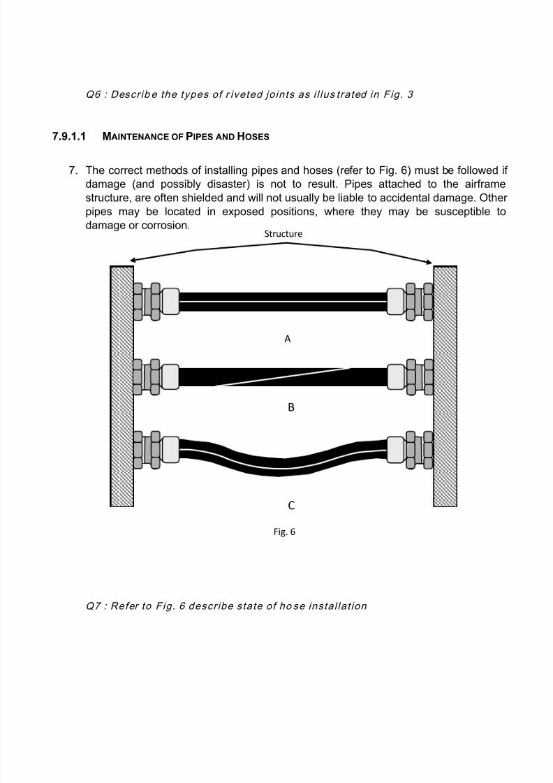
7. The correct methods of installing pipes and hoses (refer to Fig. 6) must be followed if
damage (and possibly disaster) is not to result. Pipes attached to the airframe
structure, are often shielded and will not usually be liable to accidental damage. Other
pipes may be located in exposed positions, where they may be susceptible to
damage or corrosion.
Q7 : Refer to Fig. 6 describe state of ho se insta l lat ion
A
C
Structure
B
Fig. 6

8/16/2019 MOD 7 CAT B1.1(1)
http://slidepdf.com/reader/full/mod-7-cat-b111 8/12
7.10.1 INSPECTION AND TESTING OF SPRINGS
8. Springs will generally require little in the way of maintenance. Those that are in
exposed areas can become corroded over time and those in areas of high
temperature can, if they become overheated, lose their temper and cease to have the
necessary mechanical compliance to satisfy the task for which they were designed.
Q8 : State the types of check c arr ied out in ord er to establ ished the cond it ion or
serv iceab i l ity o f sp r ing?
7.11.1.1 Installation and Misalignment
9. Installation damage is usually the result of an impact that occurs when a bearing is
fitted incorrectly. This may be due to a sharp strike from a drift or pressing the wrong
raceway when mounting the bearing.
Q9 : Describe how to d etect misal ignment of bearing ins ta l lat ion and what kind o f
ef fect o n th e bearing.

8/16/2019 MOD 7 CAT B1.1(1)
http://slidepdf.com/reader/full/mod-7-cat-b111 9/12
7.12 TRANSMISSIONS
10. There are various types of transmission mechanisms which served variable purposes
used in aircraft systems. Some of which are as listed below.
Gears
Belts and Pulleys
Chains and Sprockets
Screw Jacks
Levers
Push-Pull Rod Systems.
Q10. : State the purpo se or funct io n of gear transmiss ion sys tem
7.13.1 INSPECTION OF CONTROL CABLE PULLEYS
11. When inspecting cables for the previously mentioned wear and breakages, the
complete cable runs must be examined for incorrect routing, fraying, twisting or wear
at fairleads, pulleys and guards.
Pulleys must be inspected for wear (refer to Fig. 2), to detect indications of seizure, flat
spots, embedded foreign material and excessive tension. Any signs of contact with
adjacent structure, pipe-work, wiring and other controls must also be thoroughly
investigated.
Q11: Refer to Fig. 2 below and state the reason for defect on the pul leys
Types of Pulley Wear
Fi . 2
A
C
B
D

8/16/2019 MOD 7 CAT B1.1(1)
http://slidepdf.com/reader/full/mod-7-cat-b111 10/12
7.14.1 SHEET METAL
12. While the majority of metals can be rolled into sheet form, consideration is confined
here solely to the working with sheets of the light alloys, which are encountered on
aircraft and, in particular, those formed from aluminium alloy ingots.
By definition, sheets of aluminium alloy are comparatively thin in cross-section and,
as such, they not only pose a health hazard, through cuts, when being handled but
they are, also, prone to buckling and creasing if handled carelessly.
Q12 : Describe the method o f stor ing and h andl ing o f sheet metal

8/16/2019 MOD 7 CAT B1.1(1)
http://slidepdf.com/reader/full/mod-7-cat-b111 11/12
7.16 AIRCRAFT WEIGHT AND BALANCE
13. The main purposes, of monitoring the mass and balance of aircraft, are to maintainsafety and to achieve efficiency in flight. The position of loads such as passengers,
fuel, cargo and equipment will alter the position of the Centre of Gravity (CG) of theaircraft.
Q13. : Describe th e effect or d irect result of inc orrect loadin g o n aircraf t
per formance
7.17.1 AIRCRAFT FUELLING PROCEDURES
14.The use of the term ‘fuelling’ can include both refuelling and defueling procedures and
these notes contain examples of the essential points to be considered when refuelling
and defueling aircraft.
There may, however, be some further, local instructions, regarding the responsibilities
of the various personnel involved in fuelling procedures and these will always take
precedence in conjunction with the relevant Maintenance Manual.
Q14 : State typ es of aircraft refuell in g
7.18.1 T YPES OF DEFECTS
15. An operational aircraft can suffer from many defects and these can be defined as any
event or occurrence, which reduces the serviceability of the aircraft below 100%.
The manufacturer should specify the inspection areas and the faults, which are
expected to be found. In most instances the inspector is looking for indications of
abnormality in the item being inspected.
Q15 :
List ou t inspect ion and d efect as appl icable to all metal parts, bod ies or casings
of units in systems and in electr ical , instrum ent and radio insta l lat ions, metal
p ipes, duct in g, tubes, rods and levers.

8/16/2019 MOD 7 CAT B1.1(1)
http://slidepdf.com/reader/full/mod-7-cat-b111 12/12
7.19 ABNORMAL EVENTS
16. All aircraft are designed to withstand the normal flight and landing loads expected
during a typical flight cycle. These loads will include the normal manoeuvres the
aircraft is expected to make. The designer will build in a safety factor to compensatefor loads slightly larger than normal. Sometimes extreme circumstances occur which
causes stresses outside the normal design limits.
If the design limits are exceeded, then damage may occur to the aircraft. If it is known
or suspected that the aircraft has been subjected to excessive loads, then an
inspection should be made, to ascertain the nature of any damage that may have
occurred. The manufacturer will normally have anticipated the nature of some of
these occurrences and detailed special checks for these ‘Abnormal Occurrences’.
Q16:
The aircraf t maintenance manual wi l l norm al ly l ist the types of abnorm al
occ urrences needing s pecia l inspect ion. The l ist may vary, dependin g on the
a i rcra f t. L is t the abnormal events m ost common ly encou ntered.
7.20.1 CONTROL OF LIFE-LIMITED COMPONENTS
17.On almost any aircraft, there will be a number of components that have a stated ‘life’,usually quoted in flying hours, cycles, calendar time or operating hours.
The correct terminology for ‘life’ is Mandatory Life Limitation. The components will
have been given a life for various reasons. For example, a fatigue life on a structural
component in flying hours; the landing gear legs due for retirement after 10,000
landings, the batteries due for replacement after 3 or 4 months and a retirement life
on an APU measured in hours running time.
Q17:
Who are respon sib le for mon i tor ing and cont ro l of l i fe components and how the
procedures are be ing carr ied out?


