Modal Analysis of the Numerical Control Machine Based on Grid
Technology
Dongfang Hu1, a*, Yafei Zheng1, b and Yan Zhao2, c 1School of Mechatronics Engineering, Henan University of Science and Technology, Luoyang 471003,
China
2LandGlass Technology Co., Ltd, Luoyang 471003, China
[email protected],
[email protected],
[email protected]
Keywords: Vibration; Modal Analysis; Column; Finite Element; Grid Technology
Abstract. Vibration is a major problem in the design of high precision machining machine tool, which
has great influence on the machining precision. So it is very necessary to carry out the modal analysis
of the column components. The three-dimensional finite element model of the column was established,
and the modal analysis was carried out through ANSYS. And first five order natural frequency and
vibration mode of the column were obtained, which is helpful for us to understand the dynamic
performance of the column and to improve the machining accuracy of the machine. The complex
device of the machine tool requires the corresponding higher computing power as the basis of the
analysis. The application of the grid technology was created to solve the problem of computing power.
A computer grid platform was set up and distributed parallel computing software of ANSYS was
deployed on this platform. It proved that this platform make analysis rapid and accurate.
Introduction
The numerical control machine tools are developing for the high-speed, high-efficiency, high-precision,
and high-integration. In many cases, its performance of vibration is an essential factor to influence the
performance and improvement of the machine tool, especially in machine-tools with high-speed and
high-precision. Therefore, how to limit the effect of vibration of machine or to improve its
anti-vibration performance has become a key factor for success of design [1].
Grid technology was called the third-generation network technology. It is a new era of internet
technology after the computer equipment communication and Web technology, which acquired
communication under traditional Internet, to achieve the communication of wide area network
environment. Computers, databases, software, digital equipment are taken as infrastructure to work
together on grid technology. Thus, the grid is a kind of integrated resources and environment of
services. The target of grid is to actualize a "virtual super computer machine", which integrates
computers to work together at the same time in different locations on internet. The grid realizes
comprehensive information sharing of computing resources, storage resources, data resources,
software resources, communication resources, knowledge resources and expert resources and so on
[2].
The column is an important component of the machine tool. When the natural frequency of the
column unit is equal or close to the excitation frequency, the amplitude will sharp increase, and the
resonance will be happened. Therefore, the natural frequencies of the column unit should not be
ignored as an evaluation of the column unit. Since the machine column is a relatively complex
mechanical device, the accuracy exceedingly depends on the computer models whether it is similar to
its prototype, and the size of the cell division, which requires correspondingly higher computing power
as the basis for analysis. Until now, when conducting machine-tools performance research, single
machine analysis, which cannot solve the problem of computing power and it takes a long time, is used
widely in our nation [3]. So it is necessary to attempt the grid technology to research the machine tool
column. A computer grid platform should be set up to satisfy the analysis. As long as deploying
6th International Conference on Sensor Network and Computer Engineering (ICSNCE 2016)
© 2016. The authors - Published by Atlantis Press 269
ANSYS Linux distributed parallel computing software platform on this analysis, it could make
analysis rapid and accurate.
The object of this study is a large strong horizontal milling machine in an enterprise. Since the
process of milling belongs to accurate processing which requires high precision, column is an
important part of machine tool. So dynamic performance of column has a great influence on
processing precision. Therefore, dynamic analysis of column can help us understand its natural
frequencies and mode shapes, which are conducive to avoid unnecessary losses caused by resonance.
Modal analysis is the main method for research of dynamic performance of column. Its main content is
to determine the vibration characteristics of the column that is the natural frequency and main vibration
mode, whereby we can determine whether the modes could affect the machining accuracy. At last, we
compete the optimizing design of machine tool column, so that it could meets the requirements of the
enterprise.
Theory of Modal Analysis
[ ] ( ) [ ] ( ) [ ] ( ) ( )t t t t M X C X K X f (1)
In the type: M, C and K stand for the quality of systems, damping and rigid matrix, x(t) and f(t)
stand for displacement response vector and the inspiration force vector.
When the f(t) = 0, general solution of the homogeneous equation will reflect the free vibration
characteristics of the system, and its corresponding characteristic equation system solution features
will reflect the inherent characteristics of the structure [4].
When the f(t)≠0, it is non-homogeneous equation. Solutions of the characteristic equation will
reflect the input load characteristics. Natural frequency and main vibration mode are a natural property
of the vibration system. It is necessary to solve this problem by studying non-damped free vibration. [5]
[ ] ( ) [ ] ( ) 0t t M X K X (2)
0sin ( )t t Χ Φ (3)
In the type: Φ is a vector of N-order; ω is the vibration frequency of the vector; t is the variable of
time, t0 is time constant which is determined by the initial conditions.
2 0K Φ MΦ (4) To solve the equations above, Φ and ω are gained, and solution of (
2
1 , 1), (2
2 , 2), ..., (2
n , Φn)
is obtained. 1 , 2 , ... , n represents the N inherent frequency of the system, and the feature vector 1 ,
2, ..., Φn represents N inherent vibration of the system.
After the computer grid platform was built, ANSYS11.0 parallel computing software for Linux is
deployed on the dawn of TC4000 cluster. Node1 is set to the primary, and node2 to node8 are taken as
sub-node during the installation of the cluster. When the cluster received the assignment, the master
node will distribute the data of assignment to each child node, and then each node operates separately
and gives back the results of the operation to the primary node [6].
Model of Milling and Boring Machine Tools
Finite element analysis is based on the finite element model. whereas finite element model is a
geometric model which is generated by the element mesh. Therefore, geometric model should be
established firstly and finite element model is obtained from the geometric model.
Materials of Overall Model. The smaller parts of the model should be simplified. The main
material of the column is HT300, its material properties as follows:
Density: 7.8e3 elastic modulus: 1.3e11Pa; Poisson ratio: 0.24; track coefficient of friction: 0.2.
270
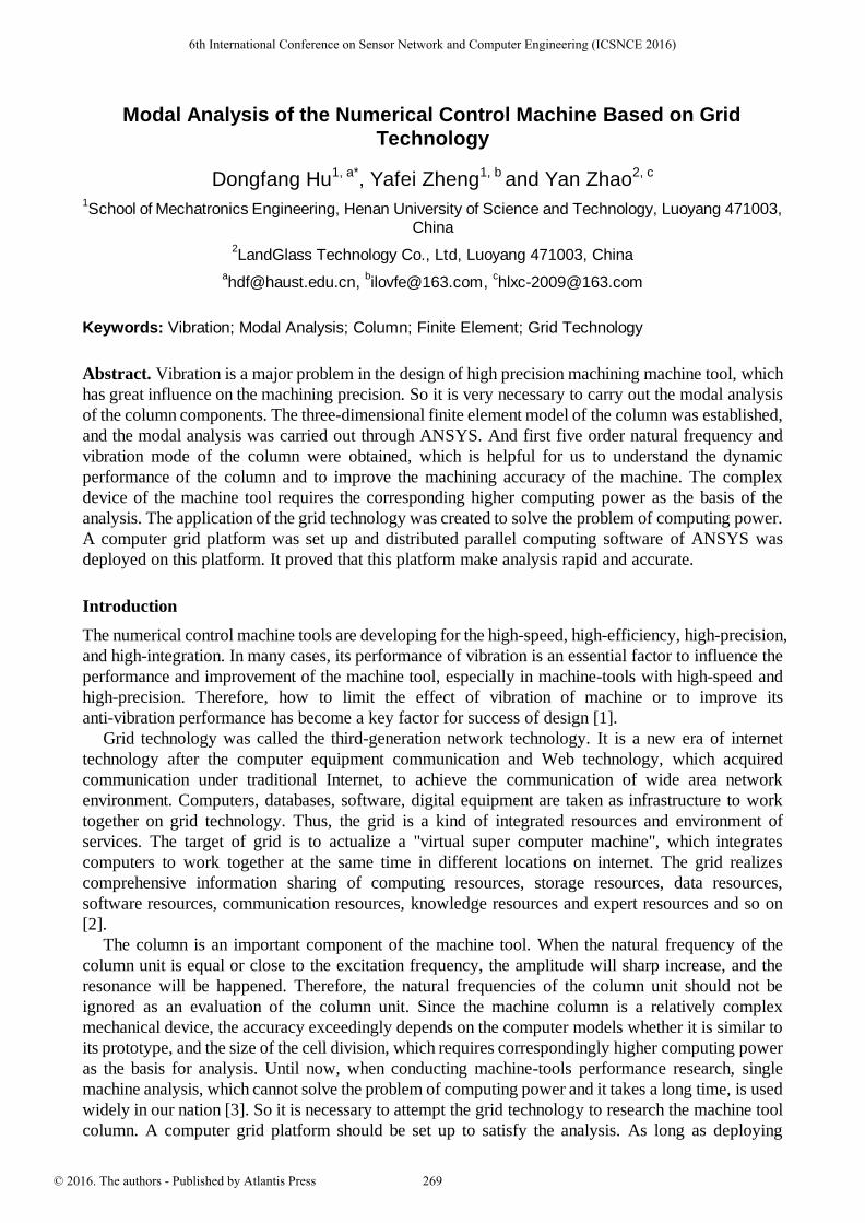
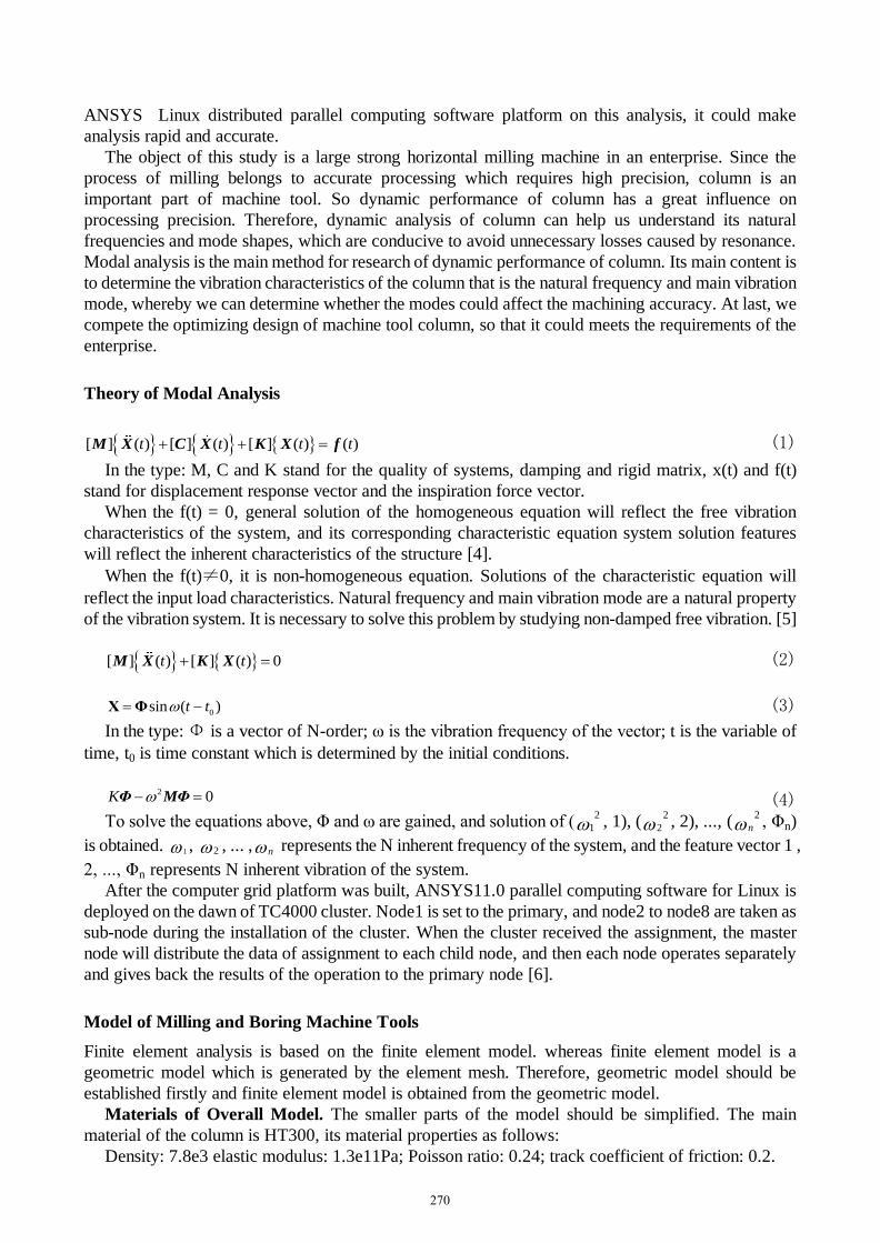
Establish of Overall Geometric Model. The establishment of overall geometric model is still very
hard even in ANSYS. According to the principle of simplified model, the details of the column, which
are little effect on overall geometric model, are simplified. Such as parts of the entity as follows,
chamfers, curving of castings, and bolt holes on the bottom [7].
The simplified geometric model sees in Fig. 1, and finite element model in ANSYS sees in Fig. 2.
Figure 1. Simplified geometric model Figure 2. Finite element model
Establish of Milling and Boring Finite Element Model. For such a complex structure of the
machine, it is difficult to obtain a finite element model by using maps or sweeping method if choose the
hexahedral elements. It takes the following principles to obtain the finite element model.
The Choice of Tetrahedral Solid Element. According to the material of the column, HT300 is
orthogonal isotropic material. 3D solid elements such as Solid45, Solid92, Solid95 and so on, are
usually used [8]. As the accuracy of analysis is a great relationship with the number of unit nodes, we
should try to choose higher-order unit. The character of common 3D elements sees table 1.
Table 1 The character of common 3D elements
Unit abbreviation node complete/curtail
integration Initial
stress remark
Solid45
Solid92
Solid95
Entity element
Tetrahedron entity element
Entity unit
8
10
20
Y/Y
Y/Y
Y/Y
Y
Y
Y
Orthogonal isotropic material
Orthogonal isotropic material
Solid45 high order element
According to the structure of milling and boring machine, if the Solid45 unit was chosen, the
accuracy is the lowest. The number of nodes depends on the type of unit chose, especially when the
number of Solid95 unit nodes is 20, the number of nodes Solid92 unit nearly 0.5 times less than
Solid95 unit. For milling and boring machine, the number of nodes is more and more, but the accuracy
is not different between Solid95 and Solid92 units. Therefor the Solid95 is usually replaced by Solid92
during the calculations [9].
Units on Contact Surface. When contact surface is set through contacting guide, it will
automatically generate the corresponding contact unit. Contact element is on the surface of the contact
layer of the model unit cell.
There are two surfaces in contact surface. The two surfaces are respective the target surface and the
contact surface. To avoid appear errors, symmetrical contact should be set, but the calculation process
has been increased by nearly one fold. The contact surface is with Contact174, and the target surface is
with Target170. The character of common contact & target elements sees Table 2.
271
Table 2 The character of common contact & target elements
Unit name Abbreviation Node Node DOF Remark
Target170
Contact174
3Dtarget element
3D8contactsurface
element
8
8
UTVMR
UTVMR
solid elements which can simulate complex shapes
solid and shell elements, which can deal with
Coulomb friction and shear stress friction.
Sets of Analysis Options
As the analysis of milling and boring is kinetic analysis, thus Antype is set to Modal. The column is
connected by screws with the bottom surface of the machine tool. It is regarded as the part of machine
tool. It is similar to a cantilever structure in kinetics. The six degrees of freedom of the column are
limited at the bottom. Therefore, according to the methods of surface constraints, UY, UZ, UX, ROTX,
RTOY, RTOZ direction of constraints are added. After constraints are added, the bottom surface is
unable to move against the machine bed. Under such circumstances, the obtained results of analysis are
the vibration of column against machine bed.
Resolver Selection
Subspace method: with high accuracy but slow calculation speed, it is applied to solve large symmetric
eigenvalue problems.
Block Lanczos: with high accuracy but calculation speed, its scope is as the same as subspace.
Deduced: with high calculation speed but low accuracy, the accuracy and speed of calculation
depends on the number and position of the selected master degrees of freedom.
Un-symmetric: it is suitable for problems of the rigid and mass matrices un-symmetric. Some of the
high frequency modes may be lost through this method.
Damping: It is applied to the problem of damping that cannot be ignored [10].
QR Damping: it is suitable for solving large problems of damping system. Its accuracy of
calculating depends on the number of modes extracted.
As to the Block Lanczos method’s character of high calculation speed and accuracy, it is usually
used to solve problems of large structure. Therefor BlockLanczos is applied to establish the finite
element model to solve the milling mode in ANSYS.
Vibration Mode of the Column
The vibration of the column can be expressed as a linear combination of the natural mode of each order.
The lower order natural vibration mode is higher than the high order to the vibration of the column. The
low order mode plays a decisive role in the dynamic characteristics of the column. So the analysis and
calculation of the vibration characteristics of the column is usually taken in the first 1-10 order. Top
10-order modal frequency of column sees table 3.
Table 3 Top 10-order modal frequency of column
Sub step response Frequency Load step
1
2
3
4
5
6
7
8
9
10
6.9820
10.920
14.832
59.118
89.713
102.52
140.87
167.57
217.24
268.38
1
1
1
1
1
1
1
1
1
1
272
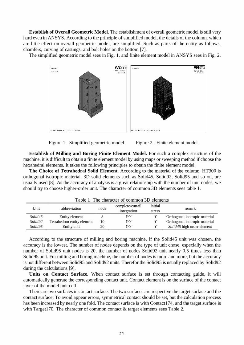
First-order mode Second-order mode Third-order mode Fourth-order mode Fifth-order mode
Figure 3. N-order mode
Conclusion
As what can be seen from the mode of vibration, the deformation of upper part of the column is
relatively obvious. The deformation gradually decreases from the top to the down. The maximum
displacement of deformation is mostly in the area of the top of the column. Due to the suspension
spindle box, the column is forced a larger bending moment. So it is necessary to strengthen the stiffness
of the column by adding the reinforcement to reduce vibration and deformation. Considering to set
aside a considerable space to install the counterweight, the inside reinforced rib is chosen, which may
ensure the strength and rigidity of the machine tool.
Taking full advantage of ANSYS to analyze the mode of the column of the milling machine, it
proved that the method is simple and convenient, and the calculation is fast. The obtained model is
intuitive and easy to understand.
Acknowledgements
The authors gratefully acknowledge the National Nature Science Foundation (Project No. 51475142),
the Key Technology R & D Program of Henan Province (Project No. 13A520232), and the Major and
Previous Pre-research Project of Henan University of Science and Technology (Project No.
2011CX016).
References
[1] Y.L. Zhang, X.D. WANG, G.Q. CAI, et al: Modular Machine Tool & Automatic Manufacturing
Technique, 2004, No.12, p.18 (In Chinese).
[2] Z. Qiao: Research on Resource Discovery in Grid Environment (MS. Lanzhou University of
Technology, China 2009), p.1.
[3] Y.J. Wang: Research and application for NC machine’s performance analysis based on the
computer grid technology (MS. Henan University of Science and Technology, China 2009), p.1.
[4] X.H. Geng, Y.T. Liu, and S.J. Wang: Equipment Manufacturing Technology, 2010, No.01, p.71
(In Chinese).
[5] Y. Hou, G.H. Zeng, and G.F. Li: Journal of Hubei University of Technology, 2010, No.04, p.118
(In Chinese).
[6] ANSYS.INC: Distributed ANSYS Guide (Help Files of ANSYS, America 2006).
[7] X.Y. Wang, T. Ning, and K. Wang: Mechanical Engineer, 2009, No.02, p.83 (In Chinese).
[8] Y.X. Zhang: Research of stress analysis to the hydraulie support (MS. Xi’an University of Science
and Technology, China 2011), p.45.
[9] Y.J. Wang, J.D. Shang, and D.F. Hu: Mechanical Engineer, 2009, No.10, p.63 (In Chinese).
[10] G.J. Zhang: Dynamic and Anti-seismic Analysis of Liquid Storage Tank (MS. Beijing University
of Chemical Technology, China 2010), p.35.
273