48
Sensing and Control Modbus® RTU Serial Communications User Manual Configuration Interface for DR4500 Supplement to 51-52-25-66 51-52-25-69 Rev A 2/00
Sensing and Control
Modbus® RTU Serial CommunicationsUser Manual
Configuration Interface for DR4500Supplement to 51-52-25-66
51-52-25-69
Rev A2/00
ii Modbus® RTU Serial Communications User Manual 2/00Configuration Interface for DR4500
Copyright, Notices, and Trademarks
Printed in U.S.A. – © Copyright 2000 by Honeywell Inc.
Revision A – 2/00
WARRANTY/REMEDY
Honeywell warrants goods of its manufacture as being free of defective materials and faultyworkmanship. Contact your local sales office for warranty information. If warranted goods arereturned to Honeywell during the period of coverage, Honeywell will repair or replace withoutcharge those items it finds defective. The foregoing is Buyer’s sole remedy and is in lieu of allother warranties, expressed or implied, including those of merchantability and fitness for aparticular purpose. Specifications may change without notice. The information we supply isbelieved to be accurate and reliable as of this printing. However, we assume no responsibility forits use.
While we provide application assistance personally, through our literature and the Honeywellweb site, it is up to the customer to determine the suitability of the product in the application.
Sensing and ControlHoneywell
11 West Spring StreetFreeport, Illinois 61032
Modbus is a registered trademark of MODICON, Inc.Windows is an addressed trademark of Microsoft Inc.
Other brand or product names are trademarks of their respective owners.
Reference: Modicon Modbus Protocol Reference Guide - PI-MBUS-300 Rev. G
2/00 Modbus® RTU Serial Communications User Manual iiiConfiguration Interface for DR4500
About This Document
AbstractThis document provides configuration information specific to Honeywell’s DR4500 recorders and shouldbe used in tandem with document number 51-52-25-66, Modbus® RTU Serial Communications UserManual.
Contacts
World Wide Web
The following lists Honeywell’s World Wide Web sites that will be of interest to our customers.
Honeywell Organization WWW Address (URL)
Corporate http://www.honeywell.com
Sensing and Control http://www.honeywell.com/sensing
International http://www.honeywell.com/Business/global.asp
Telephone
Contact us by telephone at the numbers listed below.
Organization Phone Number
United States and Canada Honeywell 1-800-423-9883 Tech. Support1-888-423-9883 Faxback1-800-525-7439 Service
Asia Pacific Honeywell Asia Pacific Inc.Hong Kong
(852) 2829-8298
Europe Honeywell PACE, Brussels, Belgium [32-2] 728-2111
Latin America Honeywell Inc., Sunrise, Florida U.S.A. (854) 845-2600

iv Modbus® RTU Serial Communications User Manual 2/00Configuration Interface for DR4500
Contents
1. OVERVIEW OF MODBUS RTU CONFIGURATION INTERFACE ........................1
2. MODBUS RTU CONFIGURATION FUNCTION CODES.......................................32.1 Register Definitions ....................................................................................................................3
2.1.1 Register Definitions - Integer Parameter (Type 1) ...................................................................32.1.2 Register Definitions - Floating Point Parameter (Type 2)........................................................32.1.3 Register Definitions - Enumerated Parameters (Type 5)..........................................................4
2.2 Function Code 20 (14h) - Read Multiple Configuration Values ................................................5
2.3 Function Code 21 (15h) - Write Multiple Configuration Values ...............................................6
3. CONFIGURATION VALUES..................................................................................73.1 Floating Point (Analog) Configuration Values...........................................................................7
3.1.1 Input Floating Point Configuration Values ..............................................................................73.1.1.1 Input 1 Values ...............................................................................................................................73.1.1.2 Input 2 Values ...............................................................................................................................73.1.1.3 Input 3 Values ...............................................................................................................................73.1.1.4 Input 4 Values ...............................................................................................................................8
3.1.2 Pen Floating Point Configuration Values.................................................................................83.1.2.1 Pen 1 Values..................................................................................................................................83.1.2.2 Pen 2 Values..................................................................................................................................83.1.2.3 Pen 3 Values..................................................................................................................................83.1.2.4 Pen 4 Values..................................................................................................................................9
3.1.3 Chart Floating Point Configuration Values..............................................................................93.1.4 Input Algorithm Point Configuration Values ...........................................................................93.1.5 Control Floating Point Configuration Values ........................................................................10
3.1.5.1 Control 1 Values..........................................................................................................................103.1.5.2 Control 2 Values..........................................................................................................................10
3.1.6 Tuning Floating Point Configuration Values .........................................................................113.1.6.1 Tuning 1 Values ..........................................................................................................................113.1.6.2 Tuning 2 Values ..........................................................................................................................11
3.1.7 SP Ramp/Rate/Program Floating Point Configuration Values...............................................113.1.7.1 SP Ramp/Rate/Program 1 Values................................................................................................113.1.7.2 SP Ramp/Rate/Program 2 Values................................................................................................123.1.7.3 Setpoint Program Segment Values ..............................................................................................12
3.1.8 Timer Floating Point Configuration Values ...........................................................................143.1.9 Alarms 1 to 6 Floating Point Configuration Values...............................................................153.1.10 Auxiliary Output Floating Point Configuration Values .......................................................153.1.11 Options Floating Point Configuration Values ......................................................................163.1.12 Event Message Floating Point Configuration Values ..........................................................16
3.2 Enumerated (Digital) Configuration Values.............................................................................173.2.1 Input Enumerated Configuration Values................................................................................17
3.2.1.1 Input 1 Values .............................................................................................................................173.2.1.2 Input 2 Values .............................................................................................................................183.2.1.3 Input 3 Values .............................................................................................................................203.2.1.4 Input 4 Enumerated Configuration Values ..................................................................................21

2/00 Modbus® RTU Serial Communications User Manual vConfiguration Interface for DR4500
3.2.2 Pen Enumerated Configuration Values ..................................................................................233.2.2.1 Pen 1 Values................................................................................................................................233.2.2.2 Pen 2 Values................................................................................................................................233.2.2.3 Pen 3 Values................................................................................................................................243.2.2.4 Pen 4 Values................................................................................................................................24
3.2.3 Chart Enumerated Configuration Values ...............................................................................253.2.4 Time Enumerated Configuration Values................................................................................253.2.5 Totalizer Enumerated Configuration Values..........................................................................26
3.2.5.1 Totalizer 1 Values .......................................................................................................................263.2.5.2 Totalizer 2 Values .......................................................................................................................273.2.5.3 Totalizer 3 Values .......................................................................................................................283.2.5.4 Totalizer 4 Values .......................................................................................................................28
3.2.6 Input Algorithm Enumerated Configuration Values ..............................................................293.2.7 Control Enumerated Configuration Values ............................................................................30
3.2.7.1 Control 1 Values..........................................................................................................................303.2.7.2 Control 2 Values..........................................................................................................................31
3.2.8 External Switch Enumerated Configuration Values...............................................................323.2.9 Tuning Enumerated Configuration Values.............................................................................32
3.2.9.1 Tuning 1 Values ..........................................................................................................................323.2.9.2 Tuning 2 Values ..........................................................................................................................32
3.2.10 SP Ramp/Rate/Program Enumerated Configuration Values ................................................333.2.10.1 SP Ramp/Rate/Program 1 Values..............................................................................................333.2.10.2 SP Ramp/Rate/Program 2 Values..............................................................................................333.2.10.3 Profile Values............................................................................................................................343.2.10.4 SP Segment Values....................................................................................................................35
3.2.11 SPP Events Enumerated Configuration Values....................................................................353.2.12 Timer Enumerated Configuration Values ............................................................................363.2.13 Alarms 1 to 6 Enumerated Configuration Values ................................................................373.2.14 Auxiliary Output Enumerated Configuration Values...........................................................393.2.15 Options Enumerated Configuration Values..........................................................................393.2.16 Event Message Enumerated Configuration Values ..............................................................403.2.17 Lockout Enumerated Configuration Values .........................................................................403.2.18 Pen Printing Enumerated Configuration Values ..................................................................40

vi Modbus® RTU Serial Communications User Manual 2/00Configuration Interface for DR4500

Overview of Modbus RTU Configuration Interface
2/00 Modbus® RTU Serial Communications User Manual 1Configuration Interface for DR4500
1. Overview of Modbus RTU Configuration Interface
This User Manual is intended to accompany the Modbus RTU Serial Communications UserManual (51-52-25-66). It describes the function codes needed to upload and download theconfiguration from a host computer into the DR4500 recorder.
Refer to document 51-52-25-66 (Modbus RTU Serial Communications User Manual) for generalModbus RTU message formatting and other information.

Overview of Modbus RTU Configuration Interface
2 Modbus® RTU Serial Communications User Manual 2/00Configuration Interface for DR4500
Modbus RTU Configuration Function Codes
2/00 Modbus® RTU Serial Communications User Manual 3Configuration Interface for DR4500
2. Modbus RTU Configuration Function Codes
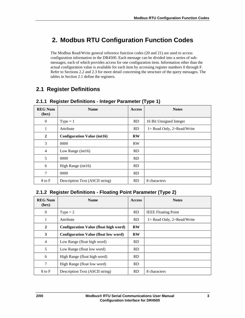
The Modbus Read/Write general reference function codes (20 and 21) are used to accessconfiguration information in the DR4500. Each message can be divided into a series of sub-messages, each of which provides access for one configuration item. Information other than theactual configuration value is available for each item by accessing register numbers 0 through F.Refer to Sections 2.2 and 2.3 for more detail concerning the structure of the query messages. Thetables in Section 2.1 define the registers.
2.1 Register Definitions
2.1.1 Register Definitions - Integer Parameter (Type 1)
REG Num(hex)
Name Access Notes
0 Type = 1 RD 16 Bit Unsigned Integer
1 Attribute RD 1= Read Only, 2=Read/Write
2 Configuration Value (int16) RW
3 0000 RW
4 Low Range (int16) RD
5 0000 RD
6 High Range (int16) RD
7 0000 RD
8 to F Description Text (ASCII string) RD 8 characters
2.1.2 Register Definitions - Floating Point Parameter (Type 2)
REG Num(hex)
Name Access Notes
0 Type = 2 RD IEEE Floating Point
1 Attribute RD 1= Read Only, 2=Read/Write
2 Configuration Value (float high word) RW
3 Configuration Value (float low word) RW
4 Low Range (float high word) RD
5 Low Range (float low word) RD
6 High Range (float high word) RD
7 High Range (float low word) RD
8 to F Description Text (ASCII string) RD 8 characters
Modbus RTU Configuration Function Codes
4 Modbus® RTU Serial Communications User Manual 2/00Configuration Interface for DR4500
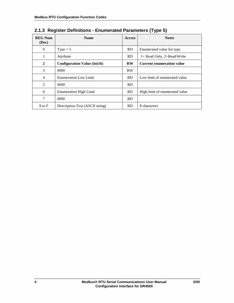
2.1.3 Register Definitions - Enumerated Parameters (Type 5)
REG Num(Dec)
Name Access Notes
0 Type = 5 RD Enumerated value list type
1 Attribute RD 1= Read Only, 2=Read/Write
2 Configuration Value (Int16) RW Current enumeration value
3 0000 RW
4 Enumeration Low Limit RD Low limit of enumerated value
5 0000 RD
6 Enumeration High Limit RD High limit of enumerated value
7 0000 RD
8 to F Description Text (ASCII string) RD 8 characters

Modbus RTU Configuration Function Codes
2/00 Modbus® RTU Serial Communications User Manual 5Configuration Interface for DR4500
2.2 Function Code 20 (14h) - Read Multiple Configuration Values
Description
Reads multiple configuration records. Each record provides access to parameter type, access,value, high and low range limits, and the ASCII prompt for that configuration item as it appears onthe DR4500 display.
Query
The query message is structured using sub-messages which define each configuration record alongwith the associated parameters desired to be read. The Reference type, included to be consistentwith the General Modbus specification, is not used. Each sub-message begins with the referencetype and is defined by a starting register and the number of registers to be read. Refer to tables inSections 2.1.1, 2.1.2, and 2.1.3 for a definition of the registers.
ATTENTION
For reading values only, the starting address is 2 (0002h) and the number of registers to read is 2(0002h).
Query message format for function code 20
SlaveAddress
FunctionCode(14h)
ByteCount
Ref Type(06)
Item #Hi
Item #Lo
StartingAddress
High
StartAddress
Low
NumberAddresses
High
NumberAddresses
Low
Ref Type(06)
Item #Hi
Item #Lo
StartingAddress
High
StartAddress
Low
NumberAddresses
High
NumberAddresses
Low
(etc) crc crc
Example:. Read one configuration value starting at 1000 and 1 value starting at 1020:
02 15 0E 06 10 00 00 02 00 02 06 10 20 00 02 00 02 crc crc
Response
The response is a series of sub-messages, each corresponding the sub-request. There is a totaloverall byte count as well as a byte count for each sub-response.
Response message format for function code 20
SlaveAddress
FunctionCode
Overallbyte
count
Subbyte
count
Reftype(06)
RegDataHi
RegDataLo
etc.Hi
etc.Lo
Subbyte
count
Reftype(06)
RegdataHi
RegdataLo
etc crc crc
Example: Reads 1.00 at 1000 and 3.00 at 1020.
02 15 0C 05 06 3F 80 00 00 08 06 40 40 00 00 crc crc
ATTENTION
Chart title, Pen range tags, and Engineering Unit strings are not supported configuration values.

Modbus RTU Configuration Function Codes
6 Modbus® RTU Serial Communications User Manual 2/00Configuration Interface for DR4500
2.3 Function Code 21 (15h) - Write Multiple Configuration Values
Description
Writes multiple configuration values.
Query
The query message is structured using sub-messages which define each configuration record alongwith the associated value to be written. The Reference type, included to be consistent with theGeneral Modbus specification, is not used. Each sub-message begins with the reference type andis defined by a starting register and the number of registers to be written followed by the data.
Query message format for function code 21
SlaveAddress
FunctionCode(14h)
ByteCount
Ref Type(06)
Item #Hi
Item #Lo
00 02 00 02
Data Hi
DataLo
DataHi
DataLo
Another sub message crc crc
Example:. Write 4 registers starting at 1000 (values 1 and 2) and 2 register starting at 1020 (value 100):
02 15 1A 06 00 00 10 00 00 04 3F 80 00 00 40 00 00 00 06 00 00 10 20 00 02 42 C8 00 00 crc crc
Response
The response is an echo of the query.
Response message format for function code 10h
SlaveAddress
FunctionCode
Overallbyte
count
Subbyte
count
RegDataHi
RegDataLo
RegDataHi
RegDataLo
etc. etc. Subbyte
count
Regdatahi
Regdatalo
etc crc crc
Configuration Values
2/00 Modbus® RTU Serial Communications User Manual 7Configuration Interface for DR4500
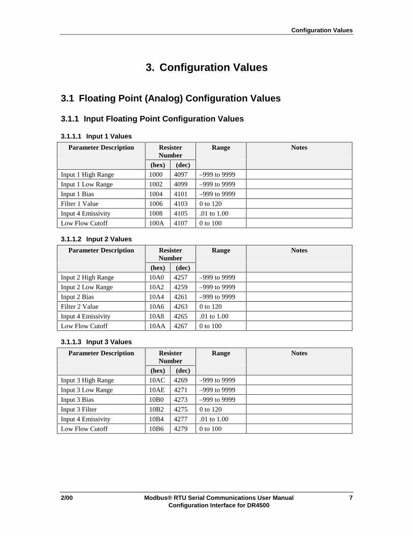
3. Configuration Values
3.1 Floating Point (Analog) Configuration Values
3.1.1 Input Floating Point Configuration Values
3.1.1.1 Input 1 Values
Parameter Description ResisterNumber
Range Notes
(hex) (dec)Input 1 High Range 1000 4097 –999 to 9999
Input 1 Low Range 1002 4099 –999 to 9999
Input 1 Bias 1004 4101 –999 to 9999
Filter 1 Value 1006 4103 0 to 120
Input 4 Emissivity 1008 4105 .01 to 1.00
Low Flow Cutoff 100A 4107 0 to 100
3.1.1.2 Input 2 Values
Parameter Description ResisterNumber
Range Notes
(hex) (dec)Input 2 High Range 10A0 4257 –999 to 9999
Input 2 Low Range 10A2 4259 –999 to 9999
Input 2 Bias 10A4 4261 –999 to 9999
Filter 2 Value 10A6 4263 0 to 120
Input 4 Emissivity 10A8 4265 .01 to 1.00
Low Flow Cutoff 10AA 4267 0 to 100
3.1.1.3 Input 3 Values
Parameter Description ResisterNumber
Range Notes
(hex) (dec)Input 3 High Range 10AC 4269 –999 to 9999
Input 3 Low Range 10AE 4271 –999 to 9999
Input 3 Bias 10B0 4273 –999 to 9999
Input 3 Filter 10B2 4275 0 to 120
Input 4 Emissivity 10B4 4277 .01 to 1.00
Low Flow Cutoff 10B6 4279 0 to 100
Configuration Values
8 Modbus® RTU Serial Communications User Manual 2/00Configuration Interface for DR4500
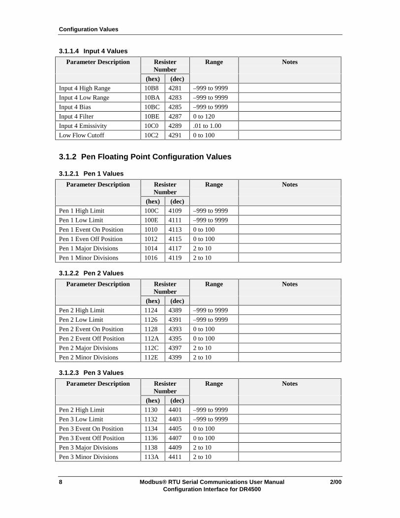
3.1.1.4 Input 4 Values
Parameter Description ResisterNumber
Range Notes
(hex) (dec)Input 4 High Range 10B8 4281 –999 to 9999
Input 4 Low Range 10BA 4283 –999 to 9999
Input 4 Bias 10BC 4285 –999 to 9999
Input 4 Filter 10BE 4287 0 to 120
Input 4 Emissivity 10C0 4289 .01 to 1.00
Low Flow Cutoff 10C2 4291 0 to 100
3.1.2 Pen Floating Point Configuration Values
3.1.2.1 Pen 1 Values
Parameter Description ResisterNumber
Range Notes
(hex) (dec)Pen 1 High Limit 100C 4109 –999 to 9999
Pen 1 Low Limit 100E 4111 –999 to 9999
Pen 1 Event On Position 1010 4113 0 to 100
Pen 1 Even Off Position 1012 4115 0 to 100
Pen 1 Major Divisions 1014 4117 2 to 10
Pen 1 Minor Divisions 1016 4119 2 to 10
3.1.2.2 Pen 2 Values
Parameter Description ResisterNumber
Range Notes
(hex) (dec)Pen 2 High Limit 1124 4389 –999 to 9999
Pen 2 Low Limit 1126 4391 –999 to 9999
Pen 2 Event On Position 1128 4393 0 to 100
Pen 2 Event Off Position 112A 4395 0 to 100
Pen 2 Major Divisions 112C 4397 2 to 10
Pen 2 Minor Divisions 112E 4399 2 to 10
3.1.2.3 Pen 3 Values
Parameter Description ResisterNumber
Range Notes
(hex) (dec)Pen 2 High Limit 1130 4401 –999 to 9999
Pen 3 Low Limit 1132 4403 –999 to 9999
Pen 3 Event On Position 1134 4405 0 to 100
Pen 3 Event Off Position 1136 4407 0 to 100
Pen 3 Major Divisions 1138 4409 2 to 10
Pen 3 Minor Divisions 113A 4411 2 to 10
Configuration Values
2/00 Modbus® RTU Serial Communications User Manual 9Configuration Interface for DR4500
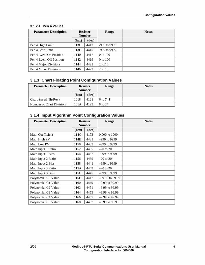
3.1.2.4 Pen 4 Values
Parameter Description ResisterNumber
Range Notes
(hex) (dec)Pen 4 High Limit 113C 4413 -999 to 9999
Pen 4 Low Limit 113E 4415 -999 to 9999
Pen 4 Event On Position 1140 4417 0 to 100
Pen 4 Event Off Position 1142 4419 0 to 100
Pen 4 Major Divisions 1144 4421 2 to 10
Pen 4 Minor Divisions 1146 4423 2 to 10
3.1.3 Chart Floating Point Configuration ValuesParameter Description Resister
NumberRange Notes
(hex) (dec)Chart Speed (Hr/Rev) 1018 4121 6 to 744
Number of Chart Divisions 101A 4123 8 to 24
3.1.4 Input Algorithm Point Configuration ValuesParameter Description Resister
NumberRange Notes
(hex) (dec)Math Coefficient 114C 4173 0.000 to 1000
Math High PV 114E 4431 –999 to 9999
Math Low PV 1150 4433 –999 to 9999
Math Input 1 Ratio 1152 4435 –20 to 20
Math Input 1 Bias 1154 4437 –999 to 9999
Math Input 2 Ratio 1156 4439 –20 to 20
Math Input 2 Bias 1158 4441 –999 to 9999
Math Input 3 Ratio 115A 4443 –20 to 20
Math Input 3 Bias 115C 4445 –999 to 9999
Polynomial C0 Value 115E 4447 –99.99 to 99.99
Polynomial C1 Value 1160 4449 –9.99 to 99.99
Polynomial C2 Value 1162 4451 –9.99 to 99.99
Polynomial C3 Value 1164 4453 –9.99 to 99.99
Polynomial C4 Value 1166 4455 –9.99 to 99.99
Polynomial C5 Value 1168 4457 –9.99 to 99.99
Configuration Values
10 Modbus® RTU Serial Communications User Manual 2/00Configuration Interface for DR4500
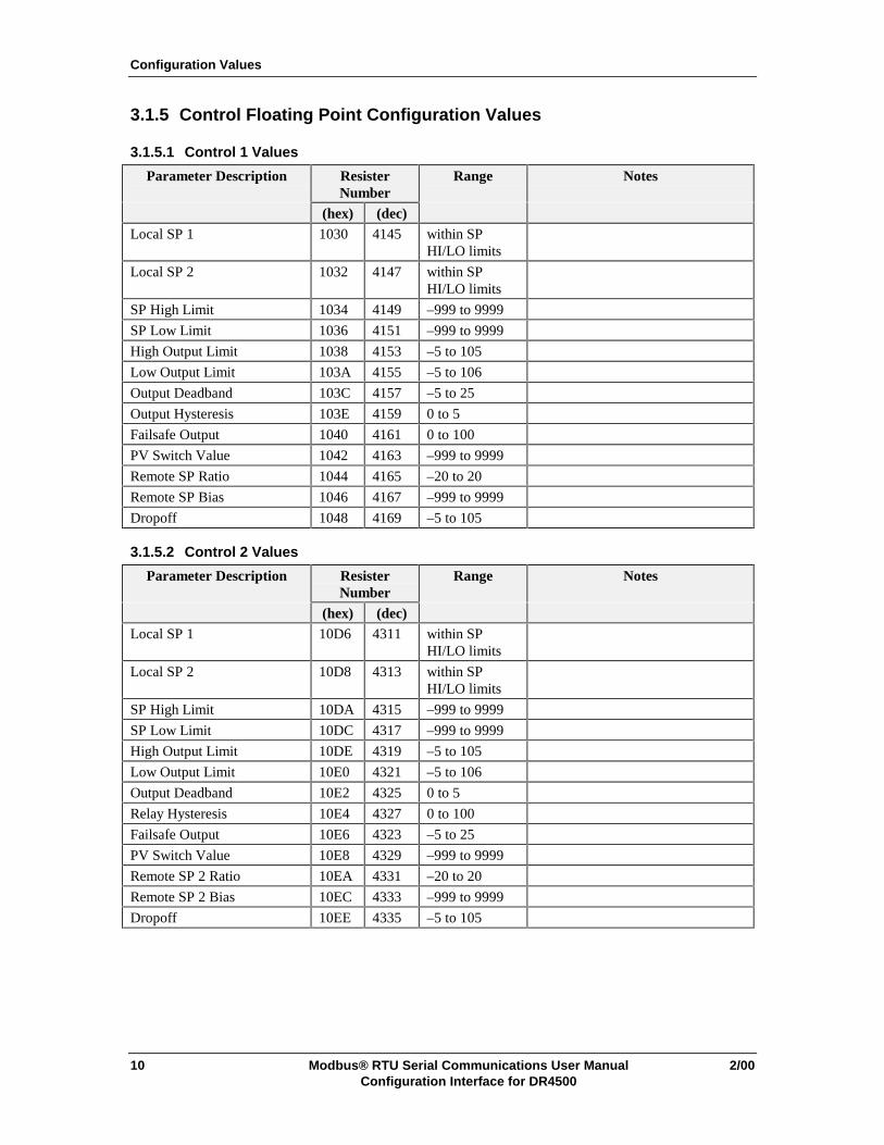
3.1.5 Control Floating Point Configuration Values
3.1.5.1 Control 1 Values
Parameter Description ResisterNumber
Range Notes
(hex) (dec)Local SP 1 1030 4145 within SP
HI/LO limits
Local SP 2 1032 4147 within SPHI/LO limits
SP High Limit 1034 4149 –999 to 9999
SP Low Limit 1036 4151 –999 to 9999
High Output Limit 1038 4153 –5 to 105
Low Output Limit 103A 4155 –5 to 106
Output Deadband 103C 4157 –5 to 25
Output Hysteresis 103E 4159 0 to 5
Failsafe Output 1040 4161 0 to 100
PV Switch Value 1042 4163 –999 to 9999
Remote SP Ratio 1044 4165 –20 to 20
Remote SP Bias 1046 4167 –999 to 9999
Dropoff 1048 4169 –5 to 105
3.1.5.2 Control 2 Values
Parameter Description ResisterNumber
Range Notes
(hex) (dec)Local SP 1 10D6 4311 within SP
HI/LO limits
Local SP 2 10D8 4313 within SPHI/LO limits
SP High Limit 10DA 4315 –999 to 9999
SP Low Limit 10DC 4317 –999 to 9999
High Output Limit 10DE 4319 –5 to 105
Low Output Limit 10E0 4321 –5 to 106
Output Deadband 10E2 4325 0 to 5
Relay Hysteresis 10E4 4327 0 to 100
Failsafe Output 10E6 4323 –5 to 25
PV Switch Value 10E8 4329 –999 to 9999
Remote SP 2 Ratio 10EA 4331 –20 to 20
Remote SP 2 Bias 10EC 4333 –999 to 9999
Dropoff 10EE 4335 –5 to 105

Configuration Values
2/00 Modbus® RTU Serial Communications User Manual 11Configuration Interface for DR4500
3.1.6 Tuning Floating Point Configuration Values
3.1.6.1 Tuning 1 Values
Parameter Description ResisterNumber
Range Notes
(hex) (dec)Heat Gain/PB 1 101E 4127 .1 to 1000Heat Rate 1 1020 4129 0 to 10Heat Reset/RPM 1 1022 4131 .02 to 50Manual Reset 1024 4133 –100 to 100Cycle Time 1 (Heat) 1026 4135 1 to 120Cool Gain/PB 2 1028 4137 .1 to 1000Cool Rate 2 102A 4139 0 to 10Cool Reset/RPM 2 102C 4141 .02 to 50Cycle Time 2 (Cool) 102E 4143 1 to 120
3.1.6.2 Tuning 2 Values
Parameter Description ResisterNumber
Range Notes
(hex) (dec)Heat Gain/PB 1 10C4 4293 .1 to 1000Heat Rate 1 10C6 4295 0 to 10Heat Reset/RPM 1 10C8 4297 .02 to 50Manual Reset 10CA 4299 –100 to 100Loop 2 Cycle Time 1 10CC 4301 1 to 120Cool Gain/PB 2 10CE 4303 .1 to 1000Cool Rate 2 10D0 4305 0 to 10Cool Reset/RPM 2 10D2 4307 .02 to 50Loop 2 Cycle Time 2 10D4 4309 1 to 120
3.1.7 SP Ramp/Rate/Program Floating Point Configuration Values
3.1.7.1 SP Ramp/Rate/Program 1 Values
Parameter Description ResisterNumber
Range Notes
(hex) (dec)Ramp Time 1056 4183 0 to 255Ramp Final SP 1058 4185 within SP
HI/LO limitsSP Rate Up Limit Value 105A 4187 0 to 9999SP Rate Down Limit Value 105C 4189 0 to 9999SPP Recycles 1060 4193 0 to 99SPP Soak Deviation 1062 4195 0.0 to 99Profile 105E 4191 1 to 6

Configuration Values
12 Modbus® RTU Serial Communications User Manual 2/00Configuration Interface for DR4500
3.1.7.2 SP Ramp/Rate/Program 2 Values
Parameter Description ResisterNumber
Range Notes
(hex) (dec)Ramp Time 10F2 4339 0 to 255Ramp Final SP 10F4 4341 within SP
HI/LO limitsSP Rate Up Limit Value 10F6 4343 0 to 9999SP Rate Down Limit Value 10F8 4345 0 to 9999SPP Recycles 10FC 4349 0 to 99SPP Soak Deviation 10FE 4351 0 to 100Profile 10FA 4347 1 to 6
3.1.7.3 Setpoint Program Segment Values
Parameter Description ResisterNumber
Range Notes
(hex) (dec)SPP Segment 1 Ramp Time 1064 4197 0.0 to 99.59 Any decimal number accepted
(e.g., 10.87 = 10 hours, 87 minutes)SPP Segment 2 Soak SP 1066 4199 within SP
HI/LO limitsSPP Segment 2 Soak Time 1068 4201 0.0 to 99.59 Any decimal number accepted
(e.g., 10.87 = 10 hours, 87 minutes)SPP Segment 3 Ramp Time 106A 4203 0.0 to 99.59 Any decimal number accepted
(e.g., 10.87 = 10hrs, 87 minutes)SPP Segment 4 Soak SP 106C 4205 within SP
HI/LO limitsSPP Segment 4 Soak Time 106E 4207 0.0 to 99.59 Any decimal number accepted
(e.g., 10.87 = 10 hours, 87 minutes)SPP Segment 5 Ramp Time 1070 4209 0.0 to 99.59 Any decimal number accepted
(e.g., 10.87 = 10 hours, 87 minutes)SPP Segment 6 Soak SP 1072 4211 within SP hi/lo
limitsSPP Segment 6 Soak Time 1074 4213 0.0 to 99.59 Any decimal number accepted
(e.g., 10.87 = 10 hours, 87 minutes)SPP Segment 7 Ramp Time 1076 4215 0.0 to 99.59 Any decimal number accepted
(e.g., 10.87 = 10 hours, 87 minutes)SPP Segment 8 Soak SP 1078 4217 within SP
HI/LO limitsSPP Segment 8 Soak Time 107A 4219 0.0 to 99.59 Any decimal number accepted
(e.g., 10.87 = 10 hours, 87 minutes)SPP Segment 9 Ramp Time 107C 4221 0.0 to 99.59 Any decimal number accepted
(e.g., 10.87 = 10 hours, 87 minutes)SPP Segment 10 Soak SP 107E 4223 within SP
HI/LO limitsSPP Segment 10 Soak Time 1080 4225 0.0 to 99.59 Any decimal number accepted
(e.g., 10.87 = 10 hours, 87 minutes)SPP Segment 11 Ramp Time 1082 4227 0.0 to 99.59 Any decimal number accepted
(e.g., 10.87 = 10 hours, 87 minutes)

Configuration Values
2/00 Modbus® RTU Serial Communications User Manual 13Configuration Interface for DR4500
Parameter Description ResisterNumber
Range Notes
(hex) (dec)SPP Segment 12 Soak SP 1084 4229 within SP
HI/LO limitsSPP Segment 12 Soak Time 1086 4231 0.0 to 99.59 Any decimal number accepted
(e.g., 10.87 = 10 hours, 87 minutes)SPP Segment 13 Ramp Time 1100 4353 0.0 to 99.59 Any decimal number accepted
(e.g., 10.87 = 10 hours, 87 minutes)SPP Segment 14 Soak SP 1102 4355 within SP
HI/LO limitsSPP Segment 14 Soak Time 1104 4357 0.0 to 99.59 Any decimal number accepted
(e.g., 10.87 = 10 hours, 87 minutes)SPP Segment 15 Ramp Time 1106 4359 0.0 to 99.59 Any decimal number accepted
(e.g., 10.87 = 10 hours, 87 minutes)SPP Segment 16 Soak SP 1108 4361 within SP
HI/LO limitsSPP Segment 16 Soak Time 110A 4363 0.0 to 99.59 Any decimal number accepted
(e.g., 10.87 = 10 hours, 87 minutes)SPP Segment 17 Ramp Time 110C 4365 0.0 to 99.59 Any decimal number accepted
(e.g., 10.87 = 10 hours, 87 minutes)SPP Segment 18 Soak SP 110E 4367 within SP
HI/LO limitsSPP Segment 18 Soak Time 1110 4369 0.0 to 99.59 Any decimal number accepted
(e.g., 10.87 = 10 hours, 87 minutes)SPP Segment 19 Ramp Time 1112 4371 0.0 to 99.59 Any decimal number accepted
(e.g., 10.87 = 10 hours, 87 minutes)SPP Segment 20 Soak SP 1114 4373 within SP
HI/LO limitsSPP Segment 20 Soak Time 1116 4375 0.0 to 99.59 Any decimal number accepted
(e.g., 10.87 = 10 hours, 87 minutes)SPP Segment 21 Ramp Time 1118 4377 0.0 to 99.59 Any decimal number accepted
(e.g., 10.87 = 10 hours, 87 minutes)SPP Segment 22 Soak SP 111A 4379 within SP
HI/LO limitsSPP Segment 22 Soak Time 111C 4381 0.0 to 99.59 Any decimal number accepted
(e.g., 10.87 = 10 hours, 87 minutes)SPP Segment 23 Ramp Time 111E 4383 0.0 to 99.59 Any decimal number accepted
(e.g., 10.87 = 10 hours, 87 minutes)SPP Segment 24 Soak SP 1120 4385 within SP
HI/LO limitsSPP Segment 24 Soak Time 1122 4387 0.0 to 99.59 Any decimal number accepted
(e.g., 10.87 = 10 hours, 87 minutes)SPP Segment 25 Ramp Time 11B0 4529 0.0 to 99.59 Any decimal number accepted
(e.g., 10.87 = 10 hours, 87 minutes)SPP Segment 26 Soak SP 11B2 4531 within SP
HI/LO limitsSPP Segment 26 Soak Time 11B4 4533 0.0 to 99.59 Any decimal number accepted
(e.g., 10.87 = 10 hours, 87 minutes)SPP Segment 27 Ramp Time 11B6 4535 0.0 to 99.59 Any decimal number accepted
(e.g., 10.87 = 10 hours, 87 minutes)
Configuration Values
14 Modbus® RTU Serial Communications User Manual 2/00Configuration Interface for DR4500
Parameter Description ResisterNumber
Range Notes
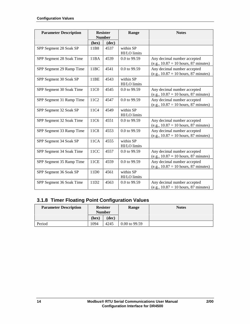
(hex) (dec)SPP Segment 28 Soak SP 11B8 4537 within SP
HI/LO limitsSPP Segment 28 Soak Time 11BA 4539 0.0 to 99.59 Any decimal number accepted
(e.g., 10.87 = 10 hours, 87 minutes)SPP Segment 29 Ramp Time 11BC 4541 0.0 to 99.59 Any decimal number accepted
(e.g., 10.87 = 10 hours, 87 minutes)SPP Segment 30 Soak SP 11BE 4543 within SP
HI/LO limitsSPP Segment 30 Soak Time 11C0 4545 0.0 to 99.59 Any decimal number accepted
(e.g., 10.87 = 10 hours, 87 minutes)SPP Segment 31 Ramp Time 11C2 4547 0.0 to 99.59 Any decimal number accepted
(e.g., 10.87 = 10 hours, 87 minutes)SPP Segment 32 Soak SP 11C4 4549 within SP
HI/LO limitsSPP Segment 32 Soak Time 11C6 4551 0.0 to 99.59 Any decimal number accepted
(e.g., 10.87 = 10 hours, 87 minutes)SPP Segment 33 Ramp Time 11C8 4553 0.0 to 99.59 Any decimal number accepted
(e.g., 10.87 = 10 hours, 87 minutes)SPP Segment 34 Soak SP 11CA 4555 within SP
HI/LO limitsSPP Segment 34 Soak Time 11CC 4557 0.0 to 99.59 Any decimal number accepted
(e.g., 10.87 = 10 hours, 87 minutes)SPP Segment 35 Ramp Time 11CE 4559 0.0 to 99.59 Any decimal number accepted
(e.g., 10.87 = 10 hours, 87 minutes)SPP Segment 36 Soak SP 11D0 4561 within SP
HI/LO limitsSPP Segment 36 Soak Time 11D2 4563 0.0 to 99.59 Any decimal number accepted
(e.g., 10.87 = 10 hours, 87 minutes)
3.1.8 Timer Floating Point Configuration ValuesParameter Description Resister
NumberRange Notes
(hex) (dec)Period 1094 4245 0.00 to 99.59
Configuration Values
2/00 Modbus® RTU Serial Communications User Manual 15Configuration Interface for DR4500
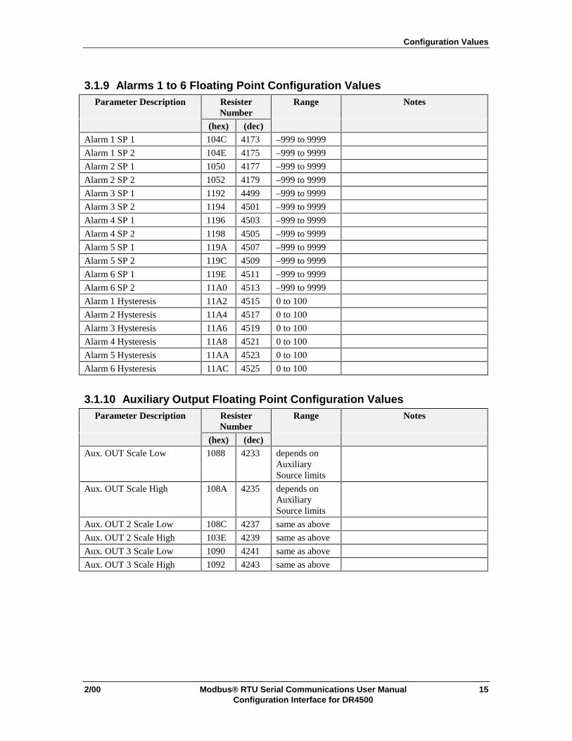
3.1.9 Alarms 1 to 6 Floating Point Configuration ValuesParameter Description Resister
NumberRange Notes
(hex) (dec)Alarm 1 SP 1 104C 4173 –999 to 9999
Alarm 1 SP 2 104E 4175 –999 to 9999
Alarm 2 SP 1 1050 4177 –999 to 9999
Alarm 2 SP 2 1052 4179 –999 to 9999
Alarm 3 SP 1 1192 4499 –999 to 9999
Alarm 3 SP 2 1194 4501 –999 to 9999
Alarm 4 SP 1 1196 4503 –999 to 9999
Alarm 4 SP 2 1198 4505 –999 to 9999
Alarm 5 SP 1 119A 4507 –999 to 9999
Alarm 5 SP 2 119C 4509 –999 to 9999
Alarm 6 SP 1 119E 4511 –999 to 9999
Alarm 6 SP 2 11A0 4513 –999 to 9999
Alarm 1 Hysteresis 11A2 4515 0 to 100
Alarm 2 Hysteresis 11A4 4517 0 to 100
Alarm 3 Hysteresis 11A6 4519 0 to 100
Alarm 4 Hysteresis 11A8 4521 0 to 100
Alarm 5 Hysteresis 11AA 4523 0 to 100
Alarm 6 Hysteresis 11AC 4525 0 to 100
3.1.10 Auxiliary Output Floating Point Configuration ValuesParameter Description Resister
NumberRange Notes
(hex) (dec)Aux. OUT Scale Low 1088 4233 depends on
AuxiliarySource limits
Aux. OUT Scale High 108A 4235 depends onAuxiliarySource limits
Aux. OUT 2 Scale Low 108C 4237 same as above
Aux. OUT 2 Scale High 103E 4239 same as above
Aux. OUT 3 Scale Low 1090 4241 same as above
Aux. OUT 3 Scale High 1092 4243 same as above

Configuration Values
16 Modbus® RTU Serial Communications User Manual 2/00Configuration Interface for DR4500
3.1.11 Options Floating Point Configuration ValuesParameter Description Resister
NumberRange Notes
(hex) (dec)Atmospheric Pressure 1148 4425 590 to 800
Deviation Setpoint 114A 4427 –999 to 9999
3.1.12 Event Message Floating Point Configuration ValuesParameter Description Resister
NumberRange Notes
(hex) (dec)Event Message 1 Position 1170 4465 0 to 100
Event Message 2 Position 1172 4467 0 to 100
Event Message 3 Position 1174 4469 0 to 100
Event Message 4 Position 1176 4471 0 to 100
Event Message 5 Position 1178 4473 0 to 100
Event Message 6 Position 117A 4475 0 to 100

Configuration Values
2/00 Modbus® RTU Serial Communications User Manual 17Configuration Interface for DR4500
3.2 Enumerated (Digital) Configuration Values
3.2.1 Input Enumerated Configuration Values
3.2.1.1 Input 1 Values
Parameter Resister Number Range NotesDescription (hex) (dec)
Input 1 1800 6145 0 - Disable1 - Enable
Input 1 Decimal Point 1801 6146 0 - None1 - One2 - Two3 - Three
Input 1 EngineeringUnits
1802 6147 0 - Degrees F1 - Degrees C2 - None
Input 1 Actuation 1803 6148 0 - B Thermocouple1 - E Thermocouple2 - E Thermocouple low3 - J Thermocouple4 - J Thermocouple low5 - K Thermocouple6 - K Thermocouple low7 - NNM Thermocouple8 - NIC Thermocouple9 - R Thermocouple10 - S Thermocouple11 - T Thermocouple12 - T Thermocouple low13 - W Thermocouple14 - W Thermocouple low15 - 100 ohm RTD16 - 500 ohm RTD17 - 100 ohm RH18 - 4-20 mA19 - 0-10 mV20 - 10-50 mV21 - 0-5V22 - 0-10V23 - Radiamatic
For Model DR45AR only:0 - E Thermocouple1 - E Thermocouple low2 - J Thermocouple3 - J Thermocouple low4 - K Thermocouple5 - K Thermocouple low6 - S Thermocouple7 - T Thermocouple8 - T Thermocouple low9 - 100 ohm RTD10 - 200 ohm RTD Hi11 - 200 ohm RTD Lo12 - 500 ohm RTD13 - 100 ohm RH14 - 4-20 mA15 - 0-10 mV16 - 10-50 mV17 - 0-5V18 - 0-10V19 - Radiamatic
Configuration Values
18 Modbus® RTU Serial Communications User Manual 2/00Configuration Interface for DR4500
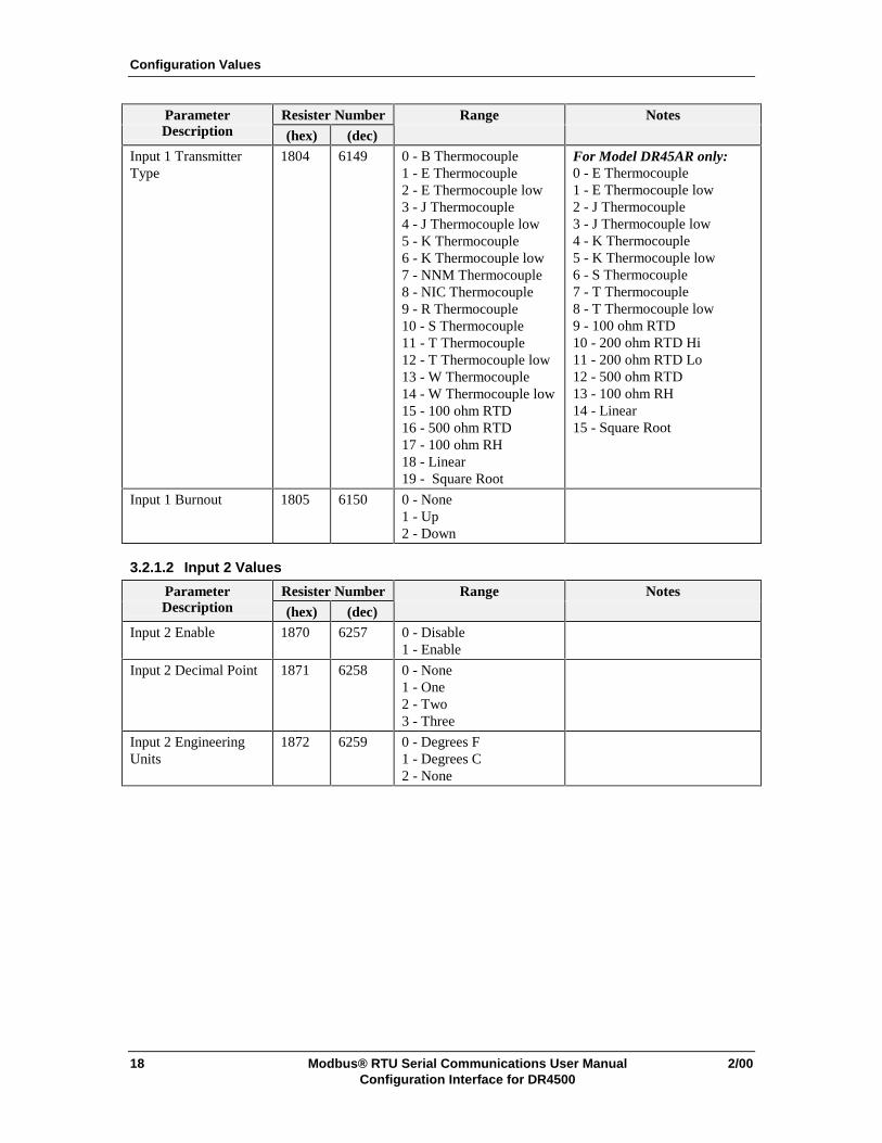
Parameter Resister Number Range NotesDescription (hex) (dec)
Input 1 TransmitterType
1804 6149 0 - B Thermocouple1 - E Thermocouple2 - E Thermocouple low3 - J Thermocouple4 - J Thermocouple low5 - K Thermocouple6 - K Thermocouple low7 - NNM Thermocouple8 - NIC Thermocouple9 - R Thermocouple10 - S Thermocouple11 - T Thermocouple12 - T Thermocouple low13 - W Thermocouple14 - W Thermocouple low15 - 100 ohm RTD16 - 500 ohm RTD17 - 100 ohm RH18 - Linear19 - Square Root
For Model DR45AR only:0 - E Thermocouple1 - E Thermocouple low2 - J Thermocouple3 - J Thermocouple low4 - K Thermocouple5 - K Thermocouple low6 - S Thermocouple7 - T Thermocouple8 - T Thermocouple low9 - 100 ohm RTD10 - 200 ohm RTD Hi11 - 200 ohm RTD Lo12 - 500 ohm RTD13 - 100 ohm RH14 - Linear15 - Square Root
Input 1 Burnout 1805 6150 0 - None1 - Up2 - Down
3.2.1.2 Input 2 Values
Parameter Resister Number Range NotesDescription (hex) (dec)
Input 2 Enable 1870 6257 0 - Disable1 - Enable
Input 2 Decimal Point 1871 6258 0 - None1 - One2 - Two3 - Three
Input 2 EngineeringUnits
1872 6259 0 - Degrees F1 - Degrees C2 - None

Configuration Values
2/00 Modbus® RTU Serial Communications User Manual 19Configuration Interface for DR4500
Parameter Resister Number Range NotesDescription (hex) (dec)
Input 2 Actuation 1873 6260 0 - B Thermocouple1 - E Thermocouple2 - E Thermocouple low3 - J Thermocouple4 - J Thermocouple low5 - K Thermocouple6 - K Thermocouple low7 - NNM Thermocouple8 - NIC Thermocouple9 - R Thermocouple10 - S Thermocouple11 - T Thermocouple12 - T Thermocouple low13 - W Thermocouple14 - W Thermocouple low15 - 100 ohm RTD16 - 500 ohm RTD17 - 100 ohm RH18 - 4-20 mA19 - 0-10 mV20 - 10-50 mV21 - 0-5V22 - 0-10V23 - Radiamatic
For Model DR45AR only:0 - E Thermocouple1 - E Thermocouple low2 - J Thermocouple3 - J Thermocouple low4 - K Thermocouple5 - K Thermocouple low6 - S Thermocouple7 - T Thermocouple8 - T Thermocouple low9 - 100 ohm RTD10 - 200 ohm RTD Hi11 - 200 ohm RTD Lo12 - 500 ohm RTD13 - 100 ohm RH14 - 4-20 mA15 - 0-10 mV16 - 10-50 mV17 - 0-5V18 - 0-10V19 - Radiamatic
Input 2 TransmitterType
1874 6261 0 - B Thermocouple1 - E Thermocouple2 - E Thermocouple low3 - J Thermocouple4 - J Thermocouple low5 - K Thermocouple6 - K Thermocouple low7 - NNM Thermocouple8 - NIC Thermocouple9 - R Thermocouple10 - S Thermocouple11 - T Thermocouple12 - T Thermocouple low13 - W Thermocouple14 - W Thermocouple low15 - 100 ohm RTD16 - 500 ohm RTD17 - 100 ohm RH18 - Linear19 - Square Root
For Model DR45AR only:0 - E Thermocouple1 - E Thermocouple low2 - J Thermocouple3 - J Thermocouple low4 - K Thermocouple5 - K Thermocouple low6 - S Thermocouple7 - T Thermocouple8 - T Thermocouple low9 - 100 ohm RTD10 - 200 ohm RTD Hi11 - 200 ohm RTD Lo12 - 500 ohm RTD13 - 100 ohm RH14 - Linear15 - Square Root
Input 2 Burnout 1875 6262 0 - None1 - Up2 - Down

Configuration Values
20 Modbus® RTU Serial Communications User Manual 2/00Configuration Interface for DR4500
3.2.1.3 Input 3 Values
Parameter Resister Number Range NotesDescription (hex) (dec)
Input 3 Enable 1878 6265 0 - Disable1 - Enable
Input 3 Decimal Point 1879 6266 0 - None1 - One2 - Two3 - Three
Input 3 EngineeringUnits
187A 6267 0 - Degrees F1 - Degrees C2 - None
Input 3 Actuation 187B 6268 0 - B Thermocouple1 - E Thermocouple2 - E Thermocouple low3 - J Thermocouple4 - J Thermocouple low5 - K Thermocouple6 - K Thermocouple low7 - NNM Thermocouple8 - NIC Thermocouple9 - R Thermocouple10 - S Thermocouple11 - T Thermocouple12 - T Thermocouple low13 - W Thermocouple14 - W Thermocouple low15 - 100 ohm RTD16 - 500 ohm RTD17 - 100 ohm RH18 - 4-20 mA19 - 0-10 mV20 - 10-50 mV21 - 0-5V22 - 0-10V23 - Radiamatic
For Model DR45AR only:0 - E Thermocouple1 - E Thermocouple low2 - J Thermocouple3 - J Thermocouple low4 - K Thermocouple5 - K Thermocouple low6 - S Thermocouple7 - T Thermocouple8 - T Thermocouple low9 - 100 ohm RTD10 - 200 ohm RTD Hi11 - 200 ohm RTD Lo12 - 500 ohm RTD13 - 100 ohm RH14 - 4-20 mA15 - 0-10 mV16 - 10-50 mV17 - 0-5V18 - 0-10V19 - Radiamatic
Configuration Values
2/00 Modbus® RTU Serial Communications User Manual 21Configuration Interface for DR4500
Parameter Resister Number Range NotesDescription (hex) (dec)
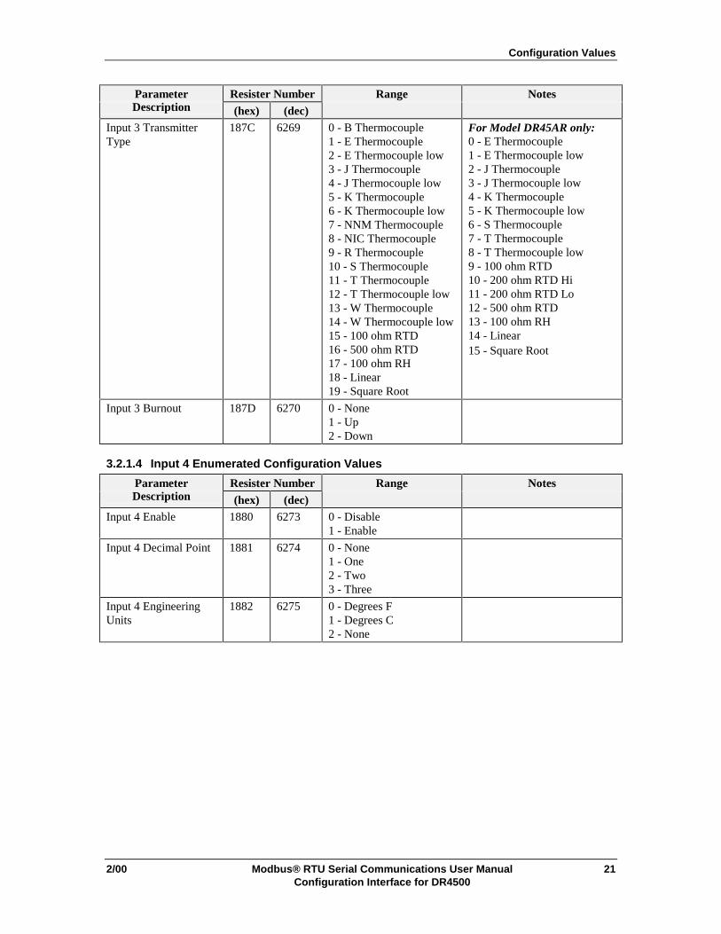
Input 3 TransmitterType
187C 6269 0 - B Thermocouple1 - E Thermocouple2 - E Thermocouple low3 - J Thermocouple4 - J Thermocouple low5 - K Thermocouple6 - K Thermocouple low7 - NNM Thermocouple8 - NIC Thermocouple9 - R Thermocouple10 - S Thermocouple11 - T Thermocouple12 - T Thermocouple low13 - W Thermocouple14 - W Thermocouple low15 - 100 ohm RTD16 - 500 ohm RTD17 - 100 ohm RH18 - Linear19 - Square Root
For Model DR45AR only:0 - E Thermocouple1 - E Thermocouple low2 - J Thermocouple3 - J Thermocouple low4 - K Thermocouple5 - K Thermocouple low6 - S Thermocouple7 - T Thermocouple8 - T Thermocouple low9 - 100 ohm RTD10 - 200 ohm RTD Hi11 - 200 ohm RTD Lo12 - 500 ohm RTD13 - 100 ohm RH14 - Linear15 - Square Root
Input 3 Burnout 187D 6270 0 - None1 - Up2 - Down
3.2.1.4 Input 4 Enumerated Configuration Values
Parameter Resister Number Range NotesDescription (hex) (dec)
Input 4 Enable 1880 6273 0 - Disable1 - Enable
Input 4 Decimal Point 1881 6274 0 - None1 - One2 - Two3 - Three
Input 4 EngineeringUnits
1882 6275 0 - Degrees F1 - Degrees C2 - None
Configuration Values
22 Modbus® RTU Serial Communications User Manual 2/00Configuration Interface for DR4500
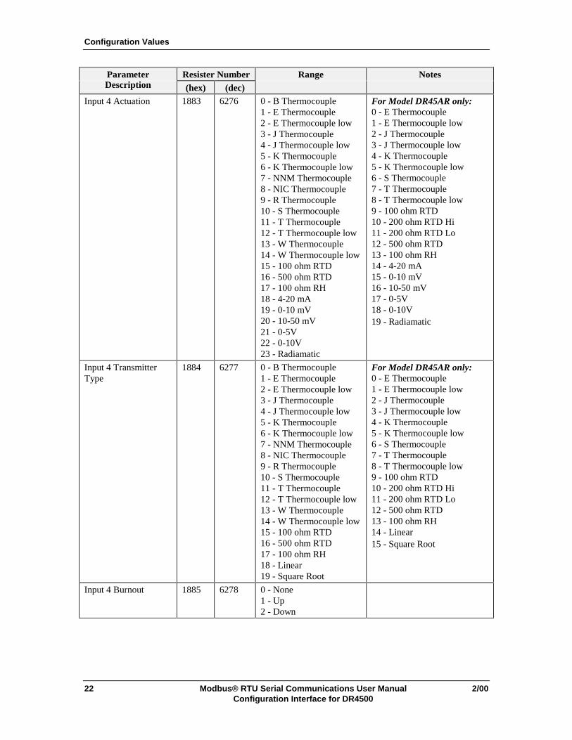
Parameter Resister Number Range NotesDescription (hex) (dec)
Input 4 Actuation 1883 6276 0 - B Thermocouple1 - E Thermocouple2 - E Thermocouple low3 - J Thermocouple4 - J Thermocouple low5 - K Thermocouple6 - K Thermocouple low7 - NNM Thermocouple8 - NIC Thermocouple9 - R Thermocouple10 - S Thermocouple11 - T Thermocouple12 - T Thermocouple low13 - W Thermocouple14 - W Thermocouple low15 - 100 ohm RTD16 - 500 ohm RTD17 - 100 ohm RH18 - 4-20 mA19 - 0-10 mV20 - 10-50 mV21 - 0-5V22 - 0-10V23 - Radiamatic
For Model DR45AR only:0 - E Thermocouple1 - E Thermocouple low2 - J Thermocouple3 - J Thermocouple low4 - K Thermocouple5 - K Thermocouple low6 - S Thermocouple7 - T Thermocouple8 - T Thermocouple low9 - 100 ohm RTD10 - 200 ohm RTD Hi11 - 200 ohm RTD Lo12 - 500 ohm RTD13 - 100 ohm RH14 - 4-20 mA15 - 0-10 mV16 - 10-50 mV17 - 0-5V18 - 0-10V19 - Radiamatic
Input 4 TransmitterType
1884 6277 0 - B Thermocouple1 - E Thermocouple2 - E Thermocouple low3 - J Thermocouple4 - J Thermocouple low5 - K Thermocouple6 - K Thermocouple low7 - NNM Thermocouple8 - NIC Thermocouple9 - R Thermocouple10 - S Thermocouple11 - T Thermocouple12 - T Thermocouple low13 - W Thermocouple14 - W Thermocouple low15 - 100 ohm RTD16 - 500 ohm RTD17 - 100 ohm RH18 - Linear19 - Square Root
For Model DR45AR only:0 - E Thermocouple1 - E Thermocouple low2 - J Thermocouple3 - J Thermocouple low4 - K Thermocouple5 - K Thermocouple low6 - S Thermocouple7 - T Thermocouple8 - T Thermocouple low9 - 100 ohm RTD10 - 200 ohm RTD Hi11 - 200 ohm RTD Lo12 - 500 ohm RTD13 - 100 ohm RH14 - Linear15 - Square Root
Input 4 Burnout 1885 6278 0 - None1 - Up2 - Down

Configuration Values
2/00 Modbus® RTU Serial Communications User Manual 23Configuration Interface for DR4500
3.2.2 Pen Enumerated Configuration Values
3.2.2.1 Pen 1 Values
Parameter Resister Number Range NotesDescription (hex) (dec)
Pen 1 Enable 1808 6153 0 - Disable1 - Enable
Pen 1 Source 1809 6154 0 - Input 11 - RH2 - Output 13 - Output 24 - Setpoint 15 - Setpoint 26 - Digital Input 17 - Digital Input 28 - Input 19 - Input 210 - Input 311 - Input 412 - Sterilization13 - PV1
3.2.2.2 Pen 2 Values
Parameter Resister Number Range NotesDescription (hex) (dec)
Pen 2 Enable 1869 6250 0 - Disable1 - Enable
Pen 2 Source 186A 6251 0 - Input 21 - RH2 - Output 13 - Output 24 - Setpoint 15 - Setpoint 26 - Digital Input 17 - Digital Input 28 - Input 19 - Input 210 - Input 311 - Input 412 - Sterilization13 - PV1
Configuration Values
24 Modbus® RTU Serial Communications User Manual 2/00Configuration Interface for DR4500
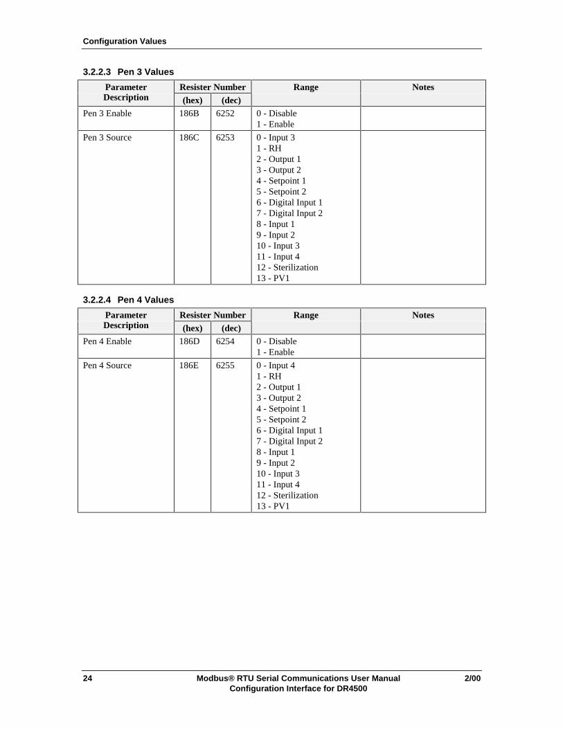
3.2.2.3 Pen 3 Values
Parameter Resister Number Range NotesDescription (hex) (dec)
Pen 3 Enable 186B 6252 0 - Disable1 - Enable
Pen 3 Source 186C 6253 0 - Input 31 - RH2 - Output 13 - Output 24 - Setpoint 15 - Setpoint 26 - Digital Input 17 - Digital Input 28 - Input 19 - Input 210 - Input 311 - Input 412 - Sterilization13 - PV1
3.2.2.4 Pen 4 Values
Parameter Resister Number Range NotesDescription (hex) (dec)
Pen 4 Enable 186D 6254 0 - Disable1 - Enable
Pen 4 Source 186E 6255 0 - Input 41 - RH2 - Output 13 - Output 24 - Setpoint 15 - Setpoint 26 - Digital Input 17 - Digital Input 28 - Input 19 - Input 210 - Input 311 - Input 412 - Sterilization13 - PV1

Configuration Values
2/00 Modbus® RTU Serial Communications User Manual 25Configuration Interface for DR4500
3.2.3 Chart Enumerated Configuration ValuesParameter Resister Number Range NotesDescription (hex) (dec)
Chart Speed Selection 180A 6155 0 - 8hr1 - 12hr2 - 24hr3 - 7day4 - Xhr
Minor Chart Divisions 180B 6156 0 - 4 divisions1 - 8 divisions
Chart Continue 180C 6157 0 - NO1 - YES
Chart Header 180D 6158 0 - NO1 - YES
Remote Chart 180E 6159 0 - None1 - External SW12 - External SW23 - Alarm 14 - Alarm 25 - Time6 - Alarm 37 - Alarm 48 - Alarm 59 - Alarm 6
3.2.4 Time Enumerated Configuration ValuesParameter Resister Number Range NotesDescription (hex) (dec)
Hours/Minutes 184B 6220 0-23, 0-59 Packed BCD format (e.g.,1505 = 15 hours, 5 minutes)
Month/Day 184C 6221 1-12, 1-31 Packed BCD format (e.g.,0318 = March 18)
Weekday/Year 184D 6222 0-6, 0-99 Packed BCD format (e.g.,0398 = Wednesday, 98)
Wake Hours/Minutes 184E 6223 0-23, 0-59 Packed BCD format (e.g.,1505 = 15 hours, 5 minutes)
Wake Month/Day 184F 6224 1-12, 1-31 Packed BCD format (e.g.,0318 = March 18)

Configuration Values
26 Modbus® RTU Serial Communications User Manual 2/00Configuration Interface for DR4500
3.2.5 Totalizer Enumerated Configuration Values
3.2.5.1 Totalizer 1 Values
Parameter Resister Number Range NotesDescription (hex) (dec)
Totalizer Enable 1837 6200 0 - Disable1 - Input 12 - Input 23 - Input 34 - Input 45 - PV16 - ETime
Totalizer IntegrationRate
1838 6201 0 - Second1 - Minute2 - Hour3 - Day4 - Million/Day
Totalizer Scale Factor 1839 6202 0 - 11 - 102 - 1003 - 10004 - 1E45 - 1E56 - 1E6
Totalizer Reset 183A 6203 0 - None1 - Keyboard2 - External SW13 - External SW24 - Time
Totalizer Inhibit 183B 6204 0 - None1 - External SW1 Open2 - External SW1 Closed3 - External SW2 Open4 - External SW2 Closed
Configuration Values
2/00 Modbus® RTU Serial Communications User Manual 27Configuration Interface for DR4500
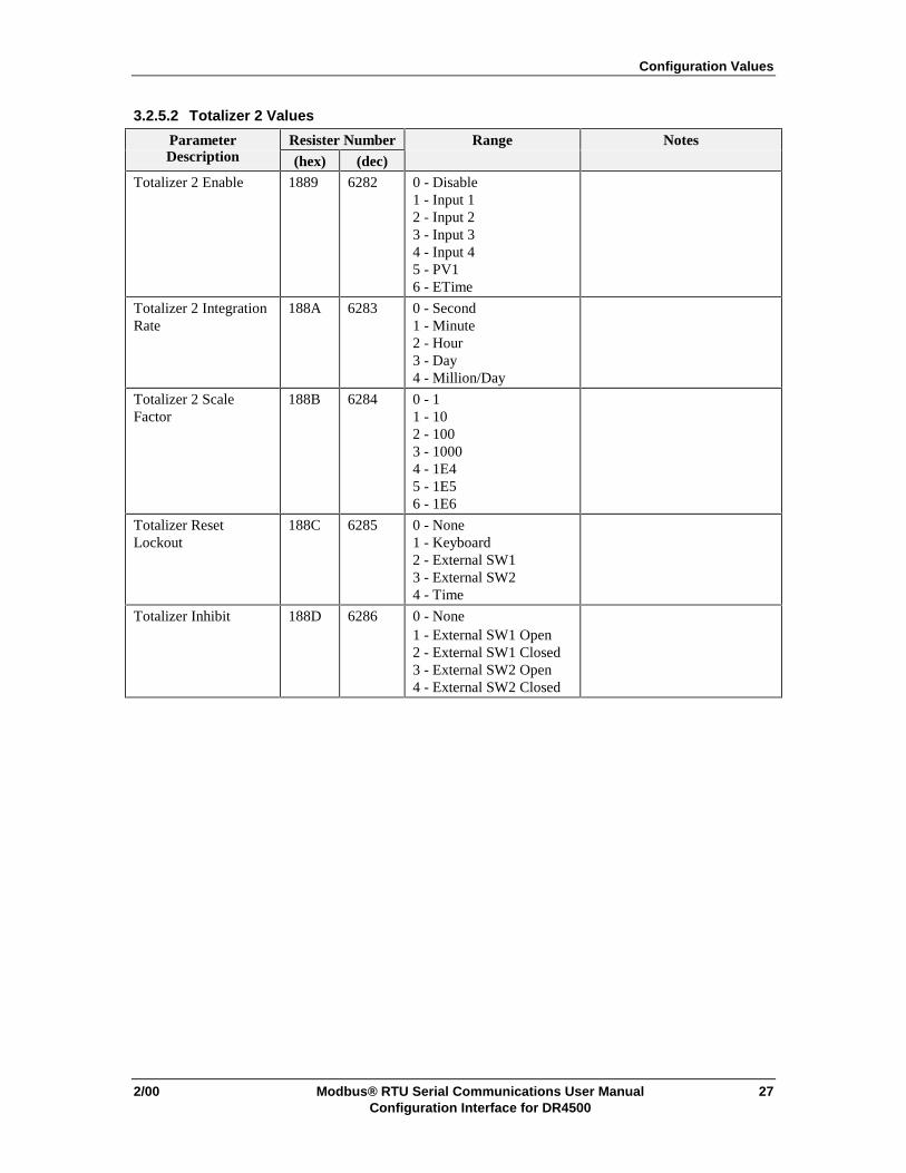
3.2.5.2 Totalizer 2 Values
Parameter Resister Number Range NotesDescription (hex) (dec)
Totalizer 2 Enable 1889 6282 0 - Disable1 - Input 12 - Input 23 - Input 34 - Input 45 - PV16 - ETime
Totalizer 2 IntegrationRate
188A 6283 0 - Second1 - Minute2 - Hour3 - Day4 - Million/Day
Totalizer 2 ScaleFactor
188B 6284 0 - 11 - 102 - 1003 - 10004 - 1E45 - 1E56 - 1E6
Totalizer ResetLockout
188C 6285 0 - None1 - Keyboard2 - External SW13 - External SW24 - Time
Totalizer Inhibit 188D 6286 0 - None1 - External SW1 Open2 - External SW1 Closed3 - External SW2 Open4 - External SW2 Closed
Configuration Values
28 Modbus® RTU Serial Communications User Manual 2/00Configuration Interface for DR4500
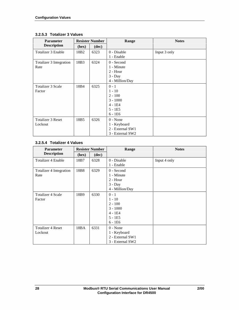
3.2.5.3 Totalizer 3 Values
Parameter Resister Number Range NotesDescription (hex) (dec)
Totalizer 3 Enable 18B2 6323 0 - Disable1 - Enable
Input 3 only
Totalizer 3 IntegrationRate
18B3 6324 0 - Second1 - Minute2 - Hour3 - Day4 - Million/Day
Totalizer 3 ScaleFactor
18B4 6325 0 - 11 - 102 - 1003 - 10004 - 1E45 - 1E56 - 1E6
Totalizer 3 ResetLockout
18B5 6326 0 - None1 - Keyboard2 - External SW13 - External SW2
3.2.5.4 Totalizer 4 Values
Parameter Resister Number Range NotesDescription (hex) (dec)
Totalizer 4 Enable 18B7 6328 0 - Disable1 - Enable
Input 4 only
Totalizer 4 IntegrationRate
18B8 6329 0 - Second1 - Minute2 - Hour3 - Day4 - Million/Day
Totalizer 4 ScaleFactor
18B9 6330 0 - 11 - 102 - 1003 - 10004 - 1E45 - 1E56 - 1E6
Totalizer 4 ResetLockout
18BA 6331 0 - None1 - Keyboard2 - External SW13 - External SW2

Configuration Values
2/00 Modbus® RTU Serial Communications User Manual 29Configuration Interface for DR4500
3.2.6 Input Algorithm Enumerated Configuration ValuesParameter Resister Number Range NotesDescription (hex) (dec)
Input Algorithm 1894 6293 0 - None1 - A+B+C2 - Square Root A*B/C3 - Square Root A*B*C4 - A*B/C5 - A*B*C6 - A–B*C7 - Hi Select8 - Lo Select
Polynomial 1896 6295 0 - Disable1 - Input 12 - Input 23 - Input 34 - Input 4

Configuration Values
30 Modbus® RTU Serial Communications User Manual 2/00Configuration Interface for DR4500
3.2.7 Control Enumerated Configuration Values
3.2.7.1 Control 1 Values
Parameter Resister Number Range NotesDescription (hex) (dec)
Control 1 Enable 1810 6161 0 - Disable1 - Enable
Control AlgorithmSelection
1811 6162 0 - On-Off1 - PID A2 - PID B3 - PD + MR4 - Three Position Step
Output Algorithm 1812 6163 0 - Time1 - Current2 - Position3 - Time Duplex4 - Current/Time5 - Time/Current
SP Source 1813 6164 0 - 1 Local1 - 2 Local2 - Remote3 - Output 2
PID Set Selection 1814 6165 0 - 1 Only1 - 2 Keyboard SW2 - PV SW3 - SP SW
LSP/RSP Tracking 1815 6166 0 - None1 - RSP
Power Up Mode 1816 6167 0 - Manual1 - Auto LSP2 - Auto RSP3 - Last mode Last SP4 - Last mode Last LSP
Control OutputDirection
1817 6168 0 - Direct1 - Reverse
Manual Mode KeyEnable
1818 6169 0 - Disable1 - Enable
Gain/PB Selection 1819 6170 0 - Gain1 - PB
Min/RPM Selection 181A 6171 0 - Minutes per repeat1 - Repeats per minute
TPSC Failsafe 181B 6172 0 - 0 %1 - 100 %
TPSC Power UpOutput Selection
181C 6173 0 - Last1 - Failsafe
Current Duplex 4-20Range Algorithm
181D 6174 0 - 100 %1 - 50 %
Configuration Values
2/00 Modbus® RTU Serial Communications User Manual 31Configuration Interface for DR4500
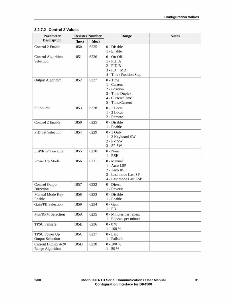
3.2.7.2 Control 2 Values
Parameter Resister Number Range NotesDescription (hex) (dec)
Control 2 Enable 1850 6225 0 - Disable1 - Enable
Control AlgorithmSelection
1851 6226 0 - On-Off1 - PID A2 - PID B3 - PD + MR4 - Three Position Step
Output Algorithm 1852 6227 0 - Time1 - Current2 - Position3 - Time Duplex4 - Current/Time5 - Time/Current
SP Source 1853 6228 0 - 1 Local1 - 2 Local2 - Remote
Control 2 Enable 1850 6225 0 - Disable1 - Enable
PID Set Selection 1854 6229 0 - 1 Only1 - 2 Keyboard SW2 - PV SW3 - SP SW
LSP/RSP Tracking 1855 6230 0 - None1 - RSP
Power Up Mode 1856 6231 0 - Manual1 - Auto LSP2 - Auto RSP3 - Last mode Last SP4 - Last mode Last LSP
Control OutputDirection
1857 6232 0 - Direct1 - Reverse
Manual Mode KeyEnable
1858 6233 0 - Disable1 - Enable
Gain/PB Selection 1859 6234 0 - Gain1 - PB
Min/RPM Selection 185A 6235 0 - Minutes per repeat1 - Repeats per minute
TPSC Failsafe 185B 6236 0 - 0 %1 - 100 %
TPSC Power UpOutput Selection
185C 6237 0 - Last1 - Failsafe
Current Duplex 4-20Range Algorithm
185D 6238 0 - 100 %1 - 50 %
Configuration Values
32 Modbus® RTU Serial Communications User Manual 2/00Configuration Interface for DR4500
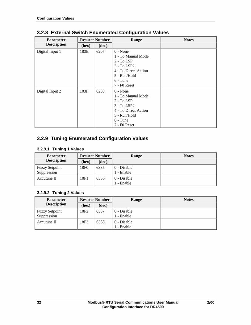
3.2.8 External Switch Enumerated Configuration ValuesParameter Resister Number Range NotesDescription (hex) (dec)
Digital Input 1 183E 6207 0 - None1 - To Manual Mode2 - To LSP3 - To LSP24 - To Direct Action5 - Run/Hold6 - Tune7 - F0 Reset
Digital Input 2 183F 6208 0 - None1 - To Manual Mode2 - To LSP3 - To LSP24 - To Direct Action5 - Run/Hold6 - Tune7 - F0 Reset
3.2.9 Tuning Enumerated Configuration Values
3.2.9.1 Tuning 1 Values
Parameter Resister Number Range NotesDescription (hex) (dec)
Fuzzy SetpointSuppression
18F0 6385 0 - Disable1 - Enable
Accutune II 18F1 6386 0 - Disable1 - Enable
3.2.9.2 Tuning 2 Values
Parameter Resister Number Range NotesDescription (hex) (dec)
Fuzzy SetpointSuppression
18F2 6387 0 - Disable1 - Enable
Accutune II 18F3 6388 0 - Disable1 - Enable
Configuration Values
2/00 Modbus® RTU Serial Communications User Manual 33Configuration Interface for DR4500
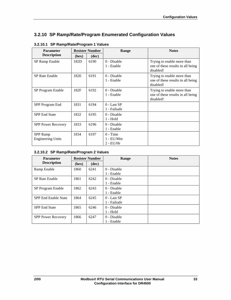
3.2.10 SP Ramp/Rate/Program Enumerated Configuration Values
3.2.10.1 SP Ramp/Rate/Program 1 Values
Parameter Resister Number Range NotesDescription (hex) (dec)
SP Ramp Enable 182D 6190 0 - Disable1 - Enable
Trying to enable more thanone of these results in all beingdisabled!
SP Rate Enable 182E 6191 0 - Disable1 - Enable
Trying to enable more thanone of these results in all beingdisabled!
SP Program Enable 182F 6192 0 - Disable1 - Enable
Trying to enable more thanone of these results in all beingdisabled!
SPP Program End 1831 6194 0 - Last SP1 - Failsafe
SPP End State 1832 6195 0 - Disable1 - Hold
SPP Power Recovery 1833 6196 0 - Disable1 - Enable
SPP RampEngineering Units
1834 6197 0 - Time1 - EU/Min2 - EU/Hr
3.2.10.2 SP Ramp/Rate/Program 2 Values
Parameter Resister Number Range NotesDescription (hex) (dec)
Ramp Enable 1860 6241 0 - Disable1 - Enable
SP Rate Enable 1861 6242 0 - Disable1 - Enable
SP Program Enable 1862 6243 0 - Disable1 - Enable
SPP End Enable State 1864 6245 0 - Last SP1 - Failsafe
SPP End State 1865 6246 0 - Disable1 - Hold
SPP Power Recovery 1866 6247 0 - Disable1 - Enable

Configuration Values
34 Modbus® RTU Serial Communications User Manual 2/00Configuration Interface for DR4500
3.2.10.3 Profile Values
Parameter Resister Number Range NotesDescription (hex) (dec)
Profile 1 Start 18E1 6370 0 - Ramp 11 - Ramp 32 - Ramp 53 - Ramp 74 - Ramp 95 - Ramp 116 - Ramp 137 - Ramp 158 - Ramp 179 - Ramp 1910 - Ramp 2111 - Ramp 2312 - Ramp 2513 - Ramp 2714 - Ramp 2915 - Ramp 3116 - Ramp 3317 - Ramp 35
Profile 1 End 18E2 6371 0 - Soak 21 - Soak 42 - Soak 63 - Soak 84 - Soak 105 - Soak 126 - Soak 147 - Soak 168 - Soak 189 - Soak 2010 - Soak 2211 - Soak 2412 - Soak 2613 - Soak 2814 - Soak 3015 - Soak 3216 - Soak 3417 - Soak 36
Profile 2 Start 18E3 6372 Same as Profile 1 StartProfile 2 End 18E4 6373 Same as Profile 1 EndProfile 3 Start 18E5 6374 Same as Profile 1 StartProfile 3 End 18E6 6375 Same as Profile 1 EndProfile 4 Start 18E7 6376 Same as Profile 1 StartProfile 4 End 18E8 6377 Same as Profile 1 EndProfile 5 Start 18E9 6378 Same as Profile 1 StartProfile 5 End 18EA 6379 Same as Profile 1 EndProfile 6 Start 18EB 6380 Same as Profile 1 StartProfile 6 End 18EC 6381 Same as Profile 1 End
Configuration Values
2/00 Modbus® RTU Serial Communications User Manual 35Configuration Interface for DR4500
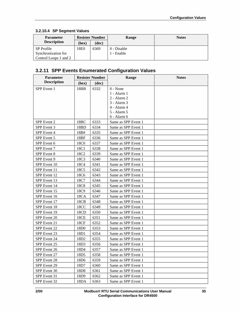
3.2.10.4 SP Segment Values
Parameter Resister Number Range NotesDescription (hex) (dec)
SP ProfileSynchronization forControl Loops 1 and 2
18E0 6369 0 - Disable1 - Enable
3.2.11 SPP Events Enumerated Configuration ValuesParameter Resister Number Range NotesDescription (hex) (dec)
SPP Event 1 18BB 6332 0 - None1 - Alarm 12 - Alarm 23 - Alarm 34 - Alarm 45 - Alarm 56 - Alarm 6
SPP Event 2 18BC 6333 Same as SPP Event 1SPP Event 3 18BD 6334 Same as SPP Event 1SPP Event 4 18B# 6335 Same as SPP Event 1SPP Event 5 18BF 6336 Same as SPP Event 1SPP Event 6 18C0 6337 Same as SPP Event 1SPP Event 7 18C1 6338 Same as SPP Event 1SPP Event 8 18C2 6339 Same as SPP Event 1SPP Event 9 18C3 6340 Same as SPP Event 1SPP Event 10 18C4 6341 Same as SPP Event 1SPP Event 11 18C5 6342 Same as SPP Event 1SPP Event 12 18C6 6343 Same as SPP Event 1SPP Event 13 18C7 6344 Same as SPP Event 1SPP Event 14 18C8 6345 Same as SPP Event 1SPP Event 15 18C9 6346 Same as SPP Event 1SPP Event 16 18CA 6347 Same as SPP Event 1SPP Event 17 18CB 6348 Same as SPP Event 1SPP Event 18 18CC 6349 Same as SPP Event 1SPP Event 19 18CD 6350 Same as SPP Event 1SPP Event 20 18CE 6351 Same as SPP Event 1SPP Event 21 18CF 6352 Same as SPP Event 1SPP Event 22 18D0 6353 Same as SPP Event 1SPP Event 23 18D1 6354 Same as SPP Event 1SPP Event 24 18D2 6355 Same as SPP Event 1SPP Event 25 18D3 6356 Same as SPP Event 1SPP Event 26 18D4 6357 Same as SPP Event 1SPP Event 27 18D5 6358 Same as SPP Event 1SPP Event 28 18D6 6359 Same as SPP Event 1SPP Event 29 18D7 6360 Same as SPP Event 1SPP Event 30 18D8 6361 Same as SPP Event 1SPP Event 31 18D9 6362 Same as SPP Event 1SPP Event 32 18DA 6363 Same as SPP Event 1
Configuration Values
36 Modbus® RTU Serial Communications User Manual 2/00Configuration Interface for DR4500
Parameter Resister Number Range NotesDescription (hex) (dec)
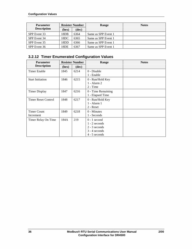
SPP Event 33 18DB 6364 Same as SPP Event 1SPP Event 34 18DC 6365 Same as SPP Event 1SPP Event 35 18DD 6366 Same as SPP Event 1SPP Event 36 18DE 6367 Same as SPP Event 1
3.2.12 Timer Enumerated Configuration ValuesParameter Resister Number Range NotesDescription (hex) (dec)
Timer Enable 1845 6214 0 - Disable1 - Enable
Start Initiation 1846 6215 0 - Run/Hold Key1 - Alarm 22 - Time
Timer Display 1847 6216 0 - Time Remaining1 - Elapsed Time
Timer Reset Control 1848 6217 0 - Run/Hold Key1 - Alarm 12 - Reset
Timer CountIncrement
1849 6218 0 - Minutes1 - Seconds
Timer Relay On Time 184A 219 0 - 1 second1 - 2 seconds2 - 3 seconds3 - 4 seconds4 - 5 seconds
Configuration Values
2/00 Modbus® RTU Serial Communications User Manual 37Configuration Interface for DR4500
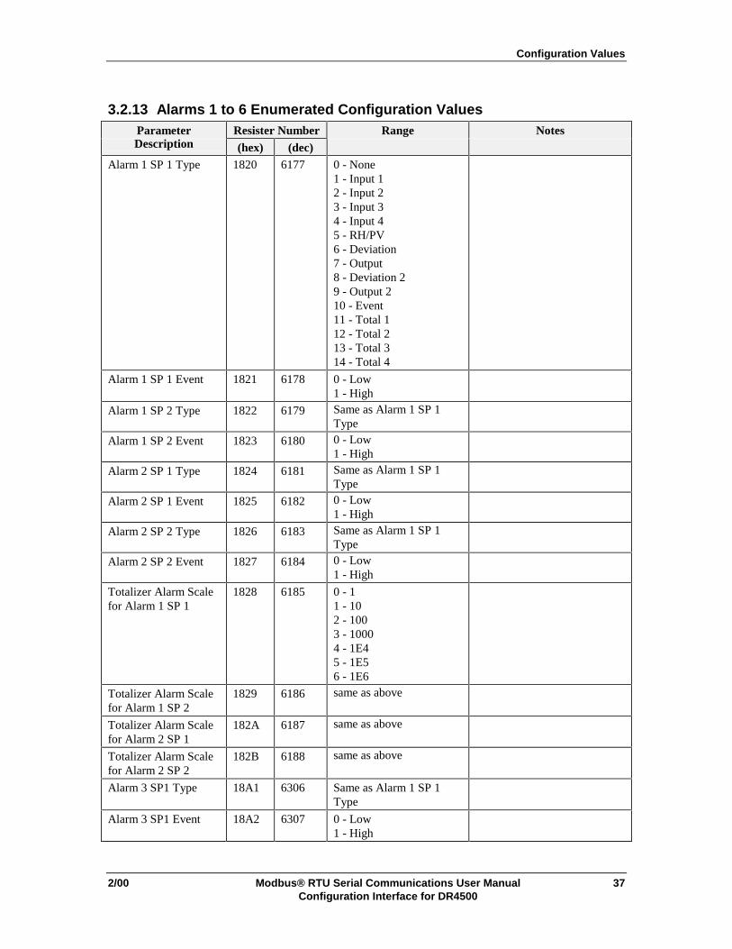
3.2.13 Alarms 1 to 6 Enumerated Configuration ValuesParameter Resister Number Range NotesDescription (hex) (dec)
Alarm 1 SP 1 Type 1820 6177 0 - None1 - Input 12 - Input 23 - Input 34 - Input 45 - RH/PV6 - Deviation7 - Output8 - Deviation 29 - Output 210 - Event11 - Total 112 - Total 213 - Total 314 - Total 4
Alarm 1 SP 1 Event 1821 6178 0 - Low1 - High
Alarm 1 SP 2 Type 1822 6179 Same as Alarm 1 SP 1Type
Alarm 1 SP 2 Event 1823 6180 0 - Low1 - High
Alarm 2 SP 1 Type 1824 6181 Same as Alarm 1 SP 1Type
Alarm 2 SP 1 Event 1825 6182 0 - Low1 - High
Alarm 2 SP 2 Type 1826 6183 Same as Alarm 1 SP 1Type
Alarm 2 SP 2 Event 1827 6184 0 - Low1 - High
Totalizer Alarm Scalefor Alarm 1 SP 1
1828 6185 0 - 11 - 102 - 1003 - 10004 - 1E45 - 1E56 - 1E6
Totalizer Alarm Scalefor Alarm 1 SP 2
1829 6186 same as above
Totalizer Alarm Scalefor Alarm 2 SP 1
182A 6187 same as above
Totalizer Alarm Scalefor Alarm 2 SP 2
182B 6188 same as above
Alarm 3 SP1 Type 18A1 6306 Same as Alarm 1 SP 1Type
Alarm 3 SP1 Event 18A2 6307 0 - Low1 - High

Configuration Values
38 Modbus® RTU Serial Communications User Manual 2/00Configuration Interface for DR4500
Parameter Resister Number Range NotesDescription (hex) (dec)
Alarm 3 SP2 Type 18A3 6308 Same as Alarm 1 SP 1Type
Alarm 3 SP2 Event 18A4 6309 0 - Low1 - High
Alarm 4 SP1 Type 18A5 6310 Same as Alarm 1 SP 1Type
Alarm 4 SP1 Event 18A6 6311 0 - Low1 - High
Alarm 4 SP2 Type 18A7 6312 Same as Alarm 1 SP 1Type
Alarm 4 SP2 Event 18A8 6313 0 - Low1 - High
Alarm 5 SP1 Type 18A9 6314 Same as Alarm 1 SP 1Type
Alarm 5 SP1 Event 18AA 6315 0 - Low1 - High
Alarm 5 SP2 Type 18AB 6316 Same as Alarm 1 SP 1Type
Alarm 5 SP2 Event 18AC 6317 0 - Low1 - High
Alarm 6 SP1 Type 18AD 6318 Same as Alarm 1 SP 1Type
Alarm 6 SP1 Event 18AE 6319 0 - Low1 - High
Alarm 6 SP2 Type 18AF 6320 Same as Alarm 1 SP 1Type
Alarm 6 SP2 Event 18B0 6321 0 - Low1 - High
Configuration Values
2/00 Modbus® RTU Serial Communications User Manual 39Configuration Interface for DR4500
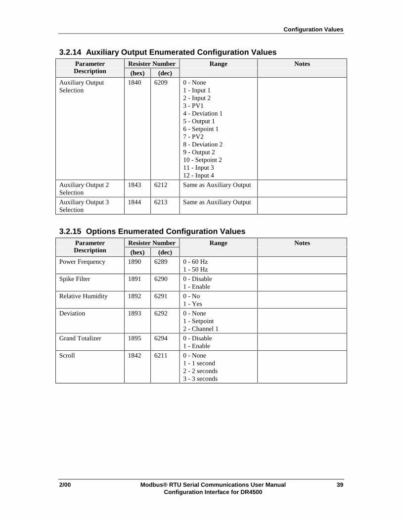
3.2.14 Auxiliary Output Enumerated Configuration ValuesParameter Resister Number Range NotesDescription (hex) (dec)
Auxiliary OutputSelection
1840 6209 0 - None1 - Input 12 - Input 23 - PV14 - Deviation 15 - Output 16 - Setpoint 17 - PV28 - Deviation 29 - Output 210 - Setpoint 211 - Input 312 - Input 4
Auxiliary Output 2Selection
1843 6212 Same as Auxiliary Output
Auxiliary Output 3Selection
1844 6213 Same as Auxiliary Output
3.2.15 Options Enumerated Configuration ValuesParameter Resister Number Range NotesDescription (hex) (dec)
Power Frequency 1890 6289 0 - 60 Hz1 - 50 Hz
Spike Filter 1891 6290 0 - Disable1 - Enable
Relative Humidity 1892 6291 0 - No1 - Yes
Deviation 1893 6292 0 - None1 - Setpoint2 - Channel 1
Grand Totalizer 1895 6294 0 - Disable1 - Enable
Scroll 1842 6211 0 - None1 - 1 second2 - 2 seconds3 - 3 seconds
Configuration Values
40 Modbus® RTU Serial Communications User Manual 2/00Configuration Interface for DR4500
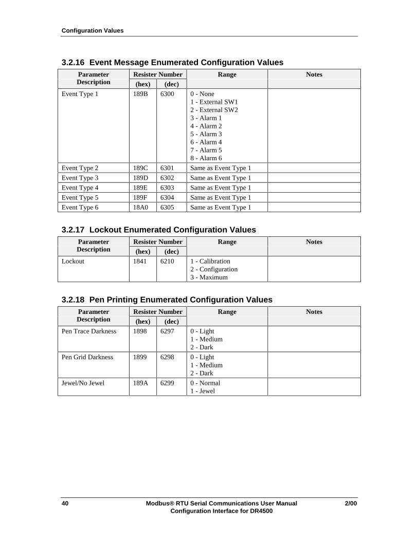
3.2.16 Event Message Enumerated Configuration ValuesParameter Resister Number Range NotesDescription (hex) (dec)
Event Type 1 189B 6300 0 - None1 - External SW12 - External SW23 - Alarm 14 - Alarm 25 - Alarm 36 - Alarm 47 - Alarm 58 - Alarm 6
Event Type 2 189C 6301 Same as Event Type 1
Event Type 3 189D 6302 Same as Event Type 1
Event Type 4 189E 6303 Same as Event Type 1
Event Type 5 189F 6304 Same as Event Type 1
Event Type 6 18A0 6305 Same as Event Type 1
3.2.17 Lockout Enumerated Configuration ValuesParameter Resister Number Range NotesDescription (hex) (dec)
Lockout 1841 6210 1 - Calibration2 - Configuration3 - Maximum
3.2.18 Pen Printing Enumerated Configuration ValuesParameter Resister Number Range NotesDescription (hex) (dec)
Pen Trace Darkness 1898 6297 0 - Light1 - Medium2 - Dark
Pen Grid Darkness 1899 6298 0 - Light1 - Medium2 - Dark
Jewel/No Jewel 189A 6299 0 - Normal1 - Jewel


Sensing and ControlHoneywell11 West Spring StreetFreeport, IL 61032
51-52-25-69A 0200 Printed in USA www.honeywell.com/sensing


