TEC-F-0520 REV1 04/30 Model 175/215/270 Steam Sterilizer powered by Pre-installation Planning Guide Skytron’s objective is to provide a program and guideline to assist individuals (hospital owners, architects, structural engineers) responsible for the Installation and operation of the sterilizer. Skytron can provide a set of drawings of the sterilizer and facility drawings showing the sterilizer set in its intended position if requested. Signed drawings are required for 270 recessed installations. Skytron is not responsible for local permits and codes.
Transcript
TEC-F-0520 REV1 04/30
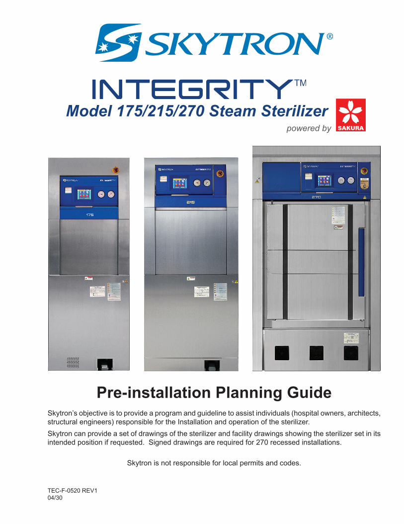
Model 175/215/270 Steam Sterilizerpowered by
Pre-installation Planning GuideSkytron’s objective is to provide a program and guideline to assist individuals (hospital owners, architects, structural engineers) responsible for the Installation and operation of the sterilizer.Skytron can provide a set of drawings of the sterilizer and facility drawings showing the sterilizer set in its intended position if requested. Signed drawings are required for 270 recessed installations.
Skytron is not responsible for local permits and codes.
COMPETENCY AND INSTALLATION REQUIREMENTS
This product is a Class 2 medical device that is subject to FDA Part 820 requirements. Installation can only take place by qualified and trained individuals. An Installation Qualification Report is required as proof of system operational validation prior to clinical use.
Contact Skytron for installation needs.
The base language for this document is ENGLISH. Any translations must be from the base language document.
Printed copies are not controlled documents.
Although current at the time of publication, SKYTRON'S policy of continuous development makes this manual subject to change without notice. If current manuals are required, contact your local SKYTRON representative or contact SKYTRON directly at the distribution address listed above.
1. SKYTRON will provide the customer with a data sheet for 175/215 sterilizer models or an equipment drawing for (specific) 270 models showing basic locations and specifications for all utilities.2. SKYTRON/DISTRIBUTOR will provide the appropriate specialized technical staff to complete final system; configuration, power up, and testing.3. SKYTRON will provide specific seismic calculations, if applicable. Seismic installation should be approved by a structural engineer.4. SKYTRON will arrange the delivery date and delivery site details with the transportation company responsible for delivering the sterilizer.
NoticeFor Integrity 270 model sterilizer (only) SKYTRON requires a minimum of 60 days delivery time from receipt of signed drawings and Order Production-Install (OPI) document.
DISTRIBUTOR/REPRESENTATIVE RESPONSIBILITIES
1. Distributor/Representative will conduct a pre-installation visit(s) to the facility to inspect the site. Identify and document any poor physical accessibility for installation and future service. Measure all openings from the receiving point to the final sterilizer location. Verify utilities Power/Water/Drain/Steam and HVAC for recessed installations.2. Distributor/Representative will become aware of any safety requirements, union requirements, applicable local codes and other site specific conditions that may apply.3. Distributor/Representative will notify Skytron, as soon as possible, of the delivery date and site details, plus any special delivery/freight truck, shipping, and/or delivery requirements.4. Distributor/Representative will communicate any change orders or project delays to Skytron.5. Distributor/Representative will make the necessary accommodations to unload and move the sterilizer into the facility at its final destination. This requires appropriate equipment, i.e. pallet jack, fork lift, or designated lifting device.6. Distributor/Representative will complete the Installation Report and Start Up Checklist to comply with FDA’s Good Manufacturing Practice and Skytron’s Device History Record, sent to Skytron immediately after start-up is complete.
CUSTOMER RESPONSIBILITIES
1. Customer will designate a representative to coordinate and approve the installation. The customer representative will be responsible for final approval of the work within ten days of completion, at which time the representative will also approve the final SKYTRON invoice.2. Customer will verify the sterilizer installation is in accordance with all applicable local codes.3. Customer will provide SKYTRON with the appropriate room drawings to include Plan, Electrical, and Mechanical Drawings if applicable for the project.4. Customer will supply and install all conduit and electrical junction boxes and complete all electrical connections in accordance with the National Electrical Code (NEC) and all applicable local and state electrical codes.Electrical connections must be installed by a qualified electrician in accordance with ANSI/NFPA70 standards, using UL (Underwriters Laboratory) recognized materials.5. Customer will test feed water supply prior to initial startup. A water test kit and analysis from Skytron (P/N WQ-TEST) may be purchased, or test locally. If mineral content exceeds the limits below, external treatment may be necessary.
Feed Water Quality Nominal Conditions
Sterilizer with facility supplied steam
Total hardness as CaCO²: 50 -120 mg/L, maximum 171 mg/L
Total Dissolved Solids: 100 -200 mg/L, maximum 500 mg/L
pH: 6.8 - 7.5, maximum 8.5
Sterilizer with Integrated Steam Generator
Total hardness as CaCO²: 0 - 17 mg/L, maximum 130 mg/L
Total Dissolved Solids: 50 -150 mg/L, maximum 250 mg/L
Total Silica: 0.1 - 1.0 mg/L, maximum 2.5 mg/L
pH: 6.8 - 7.5, maximum 8.5
Resistivity: ohm-cm 3,000 - 10,000, max 40,000Conductivity: 100 - 300 µS/cm, max 25 µS/cm
Page 2
Sterilizer Pre-installation Planning Guide • REV1
PLUMBING & UTILITY REQUIREMENTS
– Integrity™ 175 & 175SG
Recirculation Tank Overflow Drain – 1” NPT connection provided.Sanitary Floor Sink: 12” (305 mm) square x 8” (203 mm) deep with minimum 2” ID drain to accommodate peak water consumption of 2.9 gpm (11 Lpm) recommended.
Recirculation Tank Manual Drain – ⅜” ODT
Cold Water Supply – ½” NPT connection provided.Dynamic Pressure: 30 to 50 psi (0.21 - 0.34 MPa) Flow Rate: 6 gpm (22.7 Lpm)Temperature: 50° to 77° F (10 to 25 °C)Vacuum breaker, back flow preventer, and shutoff valve required.
Jacket Pressure Relief Valve – 1" NPT outlet.ASME Boiler and Pressure Vessel Code Section VIII, Div. 1, UG-135 piping practices recommended. Check local codes for special requirements.
System Electrical Power – 13’ 4” (4 m) Length Power Cord with 3 prong grounded plug provided. Dedicated Outlet: 120 VAC, 60 Hz, single phase, properly grounded and circuit protected outlet recommended.
Steam Generator Pressure Relief Valve – 1" NPT outlet.ASME Boiler and Pressure Vessel Code Section VIII, Div. 1, UG-135 piping practices recommended. Check local codes for special requirements.
Steam Generator Manual Drain – ⅜” ODT
Steam Generator Electrical Power – 208 VAC, 60 Hz, 3 phase, 50 A 480 VAC, 60 Hz, 3 phase, 20 AREQUIRED: Appropriately sized wiring L1, L2, L3 and Ground as well as a three phase, circuit protected Main Disconnect Switch (with lockout in the OFF position) located near the sterilizer.
6. Customer will provide proper drainage in accordance with applicable local codes. Temperature of drain water will not exceed 140° F (60 °C) under normal operation.7. Customer will provide all required utilities in place and in working order for SKYTRON to complete sterilizer installation and testing.Make sure that house steam and water lines are properly and completely blown down to remove construction contaminants from the system prior to making the connection to the sterilizer. A failure to do this could result in unwarranted damage to the sterilizer generating additional labor and cost to repair.If customer provided systems are not in place and working during the installation, delays may occur and result in additional charges added to the final invoice. If return trips are necessary due to a lack of customer supplied equipment, additional daily charges may occur.8. Customer and/or Distributor will be responsible for supply and installation of drywall and trim required for recessed installations.During construction, precautions must be taken to protect the sterilizer from the workers/contractors and construction materials such as: paint, drywall compounds, dust, and any other debris.
9. Customer will become familiar with the warranty coverage requirements, rights, and responsibilities. The Skytron Integrity Series Sterilizer includes a comprehensive warranty guarantee. Part of the warranty terms requires customer participation and action.
OPERATING ENVIRONMENT
• Ambient temperature: 41°-104° F (5 - 40 °C)• Relative humidity: 30% - 85% RH• Atmospheric pressure: 11.6 psi - 15.4 psi (800 - 1060 mbar)• To maintain a safe operating environment, below the maximum of 104° F (40 °C) may require ventilation equipment.
Page 3
Sterilizer Pre-installation Planning Guide • REV1
– Integrity™ 270
Recirculation Tank Overflow Drain – 1½” NPT connection provided.Sanitary Floor Sink: 12” (305 mm) square x 8” (203 mm) deep with minimum 2” ID drain to accommodate peak water consumption of 10.6 gpm (40 Lpm) recommended.
Recirculation Tank Manual Drain – ⅜” ODT
Cold Water Supply – ¾” NPT connection provided.Dynamic Pressure: 30 to 50 psi (0.21 - 0.34 MPa) Flow Rate: 6 gpm (22.7 Lpm)Temperature: 50° to 77° F (10 to 25 °C)Vacuum breaker, back flow preventer, and shutoff valve required.
Jacket Pressure Relief Valve – 1" NPT outlet.ASME Boiler and Pressure Vessel Code Section VIII, Div. 1, UG-135 piping practices recommended. Check local codes for special requirements.
System Electrical Power – 13’ 4” (4 m) Length Power Cord with 3 prong grounded plug provided. Dedicated Outlet: 120 VAC, 60 Hz, single phase, properly grounded and circuit protected outlet recommended.
Vacuum Pump Electrical Power (Optional) – 208 VAC, 60 Hz, 3 phase, 15A 480 VAC, 60 Hz, 3 phase, 7AREQUIRED: Appropriately sized wiring L1, L2, L3 and Ground as well as a three phase, circuit protected Main Disconnect Switch (with lockout in the OFF position) located near the sterilizer.
– Integrity™ 215 &215SG
Recirculation Tank Overflow Drain – 1” NPT connection provided.Sanitary Floor Sink: 12” (305 mm) square x 8” (203 mm) deep with minimum 2” ID drain to accommodate peak water consumption of 4.2 gpm (16 Lpm) recommended.
Recirculation Tank Manual Drain – ⅜” ODT
Cold Water Supply – ½” NPT connection provided.Dynamic Pressure: 30 to 50 psi (0.21 - 0.34 MPa) Flow Rate: 6 gpm (22.7 Lpm)Temperature: 50° to 70° F (10 to 21 °C).Vacuum breaker, back flow preventer, and shutoff valve required.
Jacket Pressure Relief Valve – 1" NPT outlet.ASME Boiler and Pressure Vessel Code Section VIII, Div. 1, UG-135 piping practices recommended. Check local codes for special requirements.
System Electrical Power – 13’ 4” (4 m) Length Power Cord with 3 prong grounded plug provided. Dedicated Outlet: 120 VAC, 60 Hz, single phase, properly grounded and circuit protected outlet recommended.
Steam Generator Pressure Relief Valve – 1" NPT outlet.ASME Boiler and Pressure Vessel Code Section VIII, Div. 1, UG-135 piping practices recommended.Check local codes for special requirements.
Steam Generator Manual Drain – ⅜” ODT
Steam Generator Electrical Power – 208 VAC, 60 Hz, 3 phase, 75A 480 VAC, 60 Hz, 3 phase, 33AREQUIRED: Appropriately sized wiring L1, L2, L3 and Ground as well as a three phase, circuit protected Main Disconnect Switch (with lockout in the OFF position) located near the sterilizer.