27

EMP MODEL 200/250 OPERATION MANUAL
CONTENTS…………………………………………………………………………page 1 INSTALLATION DATA………………………………………………………………... 2 MODEL 200/250 CONTROLLER……………………………………………………… 3 FS/RC SCANNER OPERATION.……………………………………………………… 4 SELECTOR SWITCH…………...……………………………………………………… 5 TRANSMISSION………………..……………………………………………………… 6 REGISTRATION MARKS……...……………………………………………………… 7 INTERNAL VIEW OF MODEL 200/250………………………………………………. 8 MODEL 200/250 INTERNAL COMPONENTS…………..…………………………… 9 MODEL 200/250 SPB SETTINGS & ALARM CONTROL……………………….. 10-11 MODEL 200/250 INTERNAL SET UP, MOTOR TYPE & LENGTH TIMING…...…. 12 MOTOR WIRING………………………….……………………………………………. 13 MOTOR STARTER WIRING……………………………………………………….….. 14 SYSTEM CHECKOUT………….………………………………………………………. 15 SET-UP & OPERATING PROCEDURE…………….……………………………... 16- 17 SET-UP & OPERATING PROCEDURE ILLUSTRATIONS…………………………. 18 TROUBLE SHOOTNG GUIDE……………………………………………………. 19- 21 CIRCUIT DESCRIPTION………………………………………………………………. 22 MODEL 200/250 INTERNAL BLOCK SCHEMATIC………………………………… 23 FRONT PANEL PARTS LIST…..……………………………………………………… 24 SELECTOR SWITCH PARTS….……………………………………………………… 25 RECOMMENDED SPARE PARTS LIST AND WARRANTY…………………….…. 26
(1)

INSTALLATION CONTROLLER The Model 200 or 250 Controller requires; (1) A clean 120VAC 50-60HZ +/- 8% With; (a) Peak Power Requirement 960 VA - 1 Second Motor Inrush (b) Peak Line Current 8 AMP (c) Steady State Line Current 2 AMP (with Motor Running) (2) The Controller must be mounted to minimize vibration. It should also be conveniently placed for operator to view all indicator LED’s for the Front Panel Adjustments. (3) All cables to the Scanner, Motors and Selector Switch should not be run with any cables from heaters, static eliminators, Main Drive Motors or power cables. SCANNER The Scanner must be firmly mounted to minimize any machine vibration. For best registration results, the Scanner should be positioned as close to the knife as possible. See Page 4 for additional information. SELECTOR SWITCH The Selector Switch must be driven in an integral relationship. (1:1, 2:1, 3:1, etc.) with the knife at a speed not exceeding the 500 RPM. Since there are adjustments made to the Selector Switch, the operator must have access to it. TRANSMISSION The DDT Transmission must be firmly secured to a flat rigid foundation. The Transmission can be secured with bolts through the slotted mounting holes on the Mount Plate. The Mount Plate must rest firmly on the foundation before bolting down. Align shafts accurately. When using direct coupling connection, a flexible coupling is recommended. If gearing or timing belts are used, the gears or pulleys should be mounted on the main shafts as close to the housing as possible. This will minimize overhung loads. GUARDS must be used since external moving parts pose a danger.
LUBRICATION All EMP Transmissions are shipped without oil. Before starting, add the specified quantity of Mobil Gear # 629 Oil. If this oil in not available, the substitute must be a 4EP Grade Oil. After the first 100 hours of operation and every 2000 hours thereafter, change the oil.
(2)

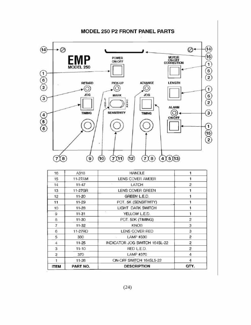
MODEL 200/250 CONTROLLER The Front Panel contains the indicators and adjustment controls necessary for proper operation. The function of each of the front panel part is as follows. Retard LED This red LED lights each time the Selector Switch vane passes
trough it’s retard area. Advanced LED This green LED lights each time the Selector Switch vane passes
through the advance area. Retard Timing Knob Used to control the timing of the Correction Motor in the retard
mode. Advanced Timing Knob Used to control the timing of the Correction Motor in the advance
mode. Retard Indicator This switch will light each time a retard correction takes place. It is and Jog Switch also used to manually jog the printed web into position. Advanced Indicator This switch will light each time an advance correction takes place. and Jog Switch It is also used to manually jog the printed web into position. Scanner LED This amber LED will flash when any printed matter is detected by
the scanner. Sensitivity Knob This adjustment varies the sensitivity of the scanner. The higher
the setting, the more sensitive the scanner is to contrasting colors. Correction Motor This switch when lit, indicates that the Correction Motor is in its ON/OFF automatic mode. Length Motor This switch when lit, indicates that the Length Motor is in its ON/OFF automatic mode. This switch is found only on the Model 250 Dual
Motor Controllers. Alarm LED This red LED flashes once an out of tolerance alarm condition
exists. Alarm On-Off This switch when on indicated that the out of tolerance system is
activated.
(3)

FS or RC SCANNER Both the RC and FS Scanners detect all colors by sensing changes in contrast. The actual detection by the Scanner takes place at either edge of the register mark. Provision is made on the Controller for selecting either a light increase or decrease at the mark’s edge. Using an example of a black mark against a white background, the scanner is stabilized by the white background. Upon detecting the leading edge of the black mark, a signal is generated when using the Dark Mark mode. If the Light Mark mode was used, the signal would be generated when leaving the register mark. Either edge of the mark may be used depending upon the relative color and contrast between the mark and it’s background. When the web is transparent, a bracket mounted under the web is required so the scanner light can be reflected back to the scanner. The bracket must provide the contrast normally provided by the web.
A foil adaptor is available for use with webs that are highly reflective (foil, etc.). The adaptor angles the Scanner for optimum detection under these conditions.
To maintain the Scanner’s performance, an occasional wipe of the lens’ surface with a Q-Tip and alcohol is recommended.
1. FS Focalite Scanners:
A focusing LED is provided with this scanner, which helps the operator bring the scanner into sharper focus. To focus the scanner correctly, perform the following steps:
1. Position the scanner about 1 inch from the web and observe the focusing L.E.D. 2. Move the scanner closer to the web slowly. The focusing L.E.D. Will begin to glow
with increasing intensity. 3. The L.E.D. will reach a maximum intensity, movement of the scanner either
towards or away from the web causes the LED to lose intensity. 4. The scanner is now correctly focused. Lock it in this position.
2. RC Scanners: Position the scanner approximately 3/8 to ½ of an inch from the web to insure correct focus. When properly focused, the scanner light will create a 1/8” round image on the web.
(4)
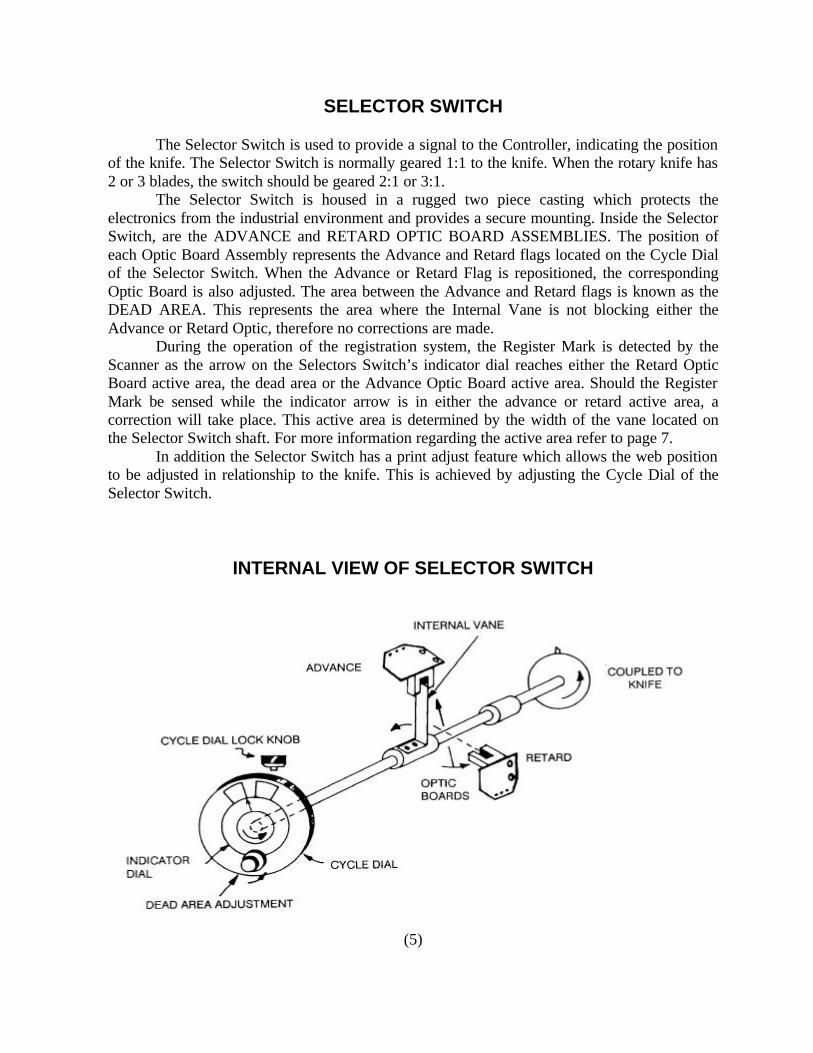
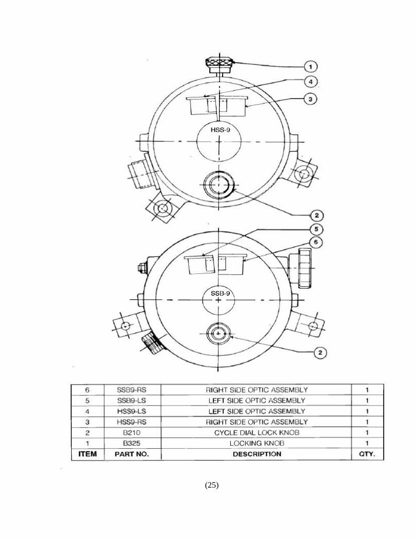
SELECTOR SWITCH The Selector Switch is used to provide a signal to the Controller, indicating the position of the knife. The Selector Switch is normally geared 1:1 to the knife. When the rotary knife has 2 or 3 blades, the switch should be geared 2:1 or 3:1. The Selector Switch is housed in a rugged two piece casting which protects the electronics from the industrial environment and provides a secure mounting. Inside the Selector Switch, are the ADVANCE and RETARD OPTIC BOARD ASSEMBLIES. The position of each Optic Board Assembly represents the Advance and Retard flags located on the Cycle Dial of the Selector Switch. When the Advance or Retard Flag is repositioned, the corresponding Optic Board is also adjusted. The area between the Advance and Retard flags is known as the DEAD AREA. This represents the area where the Internal Vane is not blocking either the Advance or Retard Optic, therefore no corrections are made. During the operation of the registration system, the Register Mark is detected by the Scanner as the arrow on the Selectors Switch’s indicator dial reaches either the Retard Optic Board active area, the dead area or the Advance Optic Board active area. Should the Register Mark be sensed while the indicator arrow is in either the advance or retard active area, a correction will take place. This active area is determined by the width of the vane located on the Selector Switch shaft. For more information regarding the active area refer to page 7. In addition the Selector Switch has a print adjust feature which allows the web position to be adjusted in relationship to the knife. This is achieved by adjusting the Cycle Dial of the Selector Switch.
INTERNAL VIEW OF SELECTOR SWITCH
(5)

TRANSMISSION
The fourth component of the EMP Register System is the Differential Transmission. Based on your application, EMP will recommend the unit that will best serve your needs. The choices are; 1 - DDT-MVC Transmission-Uses both a correction and length motor 2 - DDT Transmission-Uses only a correction motor 3 - T-2 Transmission-Uses only a correction motor 4 - ILDT Transmission-Uses only a correction motor The selection of the Transmission will also affect your choice of a Controller. The Model 250 Dual Motor Register System is required for the DDT-MVC Transmission and if an existing PIV is being motorized. All other transmissions listed operate with the Model 200 Controller since all units are single motor controllers. For all preprinted registration applications, EMP recommends the DDT-MVC or DDT Transmission. The DDT Transmission’s ability to correct both length errors as well as random register errors provides the most accurate registration. The DDT Transmission maintains the registration by regulation the speed of the machine’s Draw Rollers. The Correction Motor will receive signals from the Controller. The correction will momentary adjust the Draw Roller Speed, which will advance or retard the amount of preprinted web delivered to the knife. The Length Motor used on the DDT-MVC will make adjustments to the Variator. These adjustments correct the constant length error portion or register error. For additional information, please refer to the operating manual of the transmission used in your application.
(6)

REGISTRATION MARKS The Registration Mark is the reference that tells the Controller the printed web’s exact position. It is important that the Registration Mark have the following characteristics: 1 - Color - Since the Scanner “sees” the mark by sensing the change in colors, contrast is the key. High contrast (Dark color on light or vice versa) provides the best signal ratio and control reliability. Plan early to use bright, well defined, contrasting colors in your operation. 2 - Size - EMP recommends the mark to be a minimum of 3/8” in length and 1/8” wide. This size is recommended because the 3/8” length allows for slight side to side web drift while still remaining in the path of the Scanner. The width of 1/8” provides the scanner enough time to sense the contrast. 3 - Minimum Clear Space - To maintain proper registration, only the Register Mark can give the signal to the controller. To help the system recognize only the Register Mark, a clear unprinted area before and after the Registration Mark is required. The size of this clear area is determined by the size of the internal vane of the Selector Switch. (See chart below for vane sizes). For our example we will assume the following; 1) Standard HSS9 Switch with 30 degree active area. 2) The repeat length of the web is 12 inches. 3) The Selector Switch and Knife rotate in a 1:1 ratio. Under these circumstances, we require a 1 inch clear area before and after the Registration Mark. (30 degrees / 360degrees) X 12” Repeat Length = 1 inch Should you have any questions regarding the Registration Mark, please send sample to EMP for testing.
Selector Switch Part No. Active Area Description CCW or CW HSS9 or HSS91 30 degrees Standard HSS94 or HSS914 18 degrees Narrow Active Area SSB9 or SSB91 30 degrees Worm wheel adjustment SSB94 or SSB914 18 degrees Wormwheel Adjustment
(7)
(8)

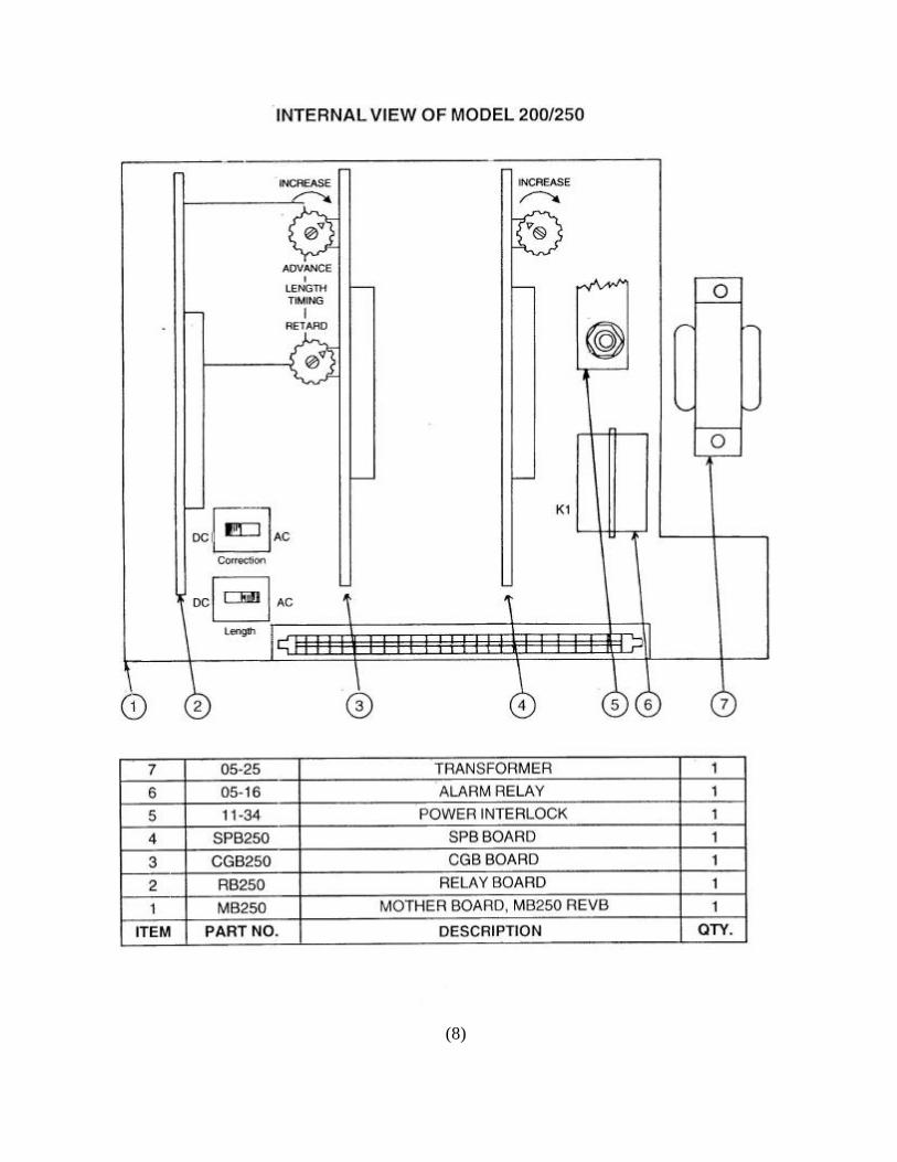
MODEL 200/250 INTERNAL COMPONENTS
The Model 200/250 consists of a main printed circuit board (MB) and three connecting printed circuit boards. The MB contains the Power Supply, Alarm Relay, Length Motor Type Switch (SW8), and Correction Motor Type Switch (SW9). A brief description of the three other boards are given below. 1. SPB-250 Board: The Scanner Processing Board contains the circuit that accepts the signal from the Scanner, and conditions the signal for use by the CGB Board. It also contains the tolerance area circuit which determines if the registration is within the established range. The switch for setting the number of out of tolerance event allowed before the alarm is energized is located on the board. Refer to page 11 for more information. 2. CGB-250 Board: The Control Generator Board compares the Scanner signal to the Selector Switch signal and determines if a correction is necessary and in which direction a correction should be made. Also located on the CGB board are the Retard and Advance Length Timing Pots. Refer to page 12 for more information. 3. RB-250 Board: The Relay Board contains the solid state relays which drive the Correction and Length Motors. The fuses which limit motor current are located on this P.C. board.
(9)
MODEL 250 INTERNAL ADJUSTMENTS
1 - ESTBLISHING THE OUT OF TOLERANCE AREA Since the registration tolerance of our customers varies, EMP has designed an adjustable Out of Tolerance circuit. Before describing how to meet your requirements, a brief description of the circuit is helpful. As the selector switch rotates, the sensors are used to electronically create a third zone, referred to as the electronic vane (EV). If a register mark is detected within the established EV zone, the registration is in tolerance, and no alarm is required. If no mark is detected within the EV zone the controller counts this as an Out of Tolerance event. After a preset number of such events, an alarm relay is activated. SW21 on the SPB Board is used to present the number of out of tolerance events, that are allowed to occur before the alarm is energized. The factory setting is 4 out of tolerance repeats before the alarm is energized. 2 - The EV pot on the SPB board adjusts the out of tolerance area. This means that the amount by which the cut may move from the “correct” position before the alarm is energized can be preset with this pot. (See chart on page 11). To convert from degrees to inches to use this formula; (repeat length x degrees) /360 = allowed OUT of TOL inches 3 - Some machines have Selector Switches that rotate while waiting for product. These machines should have SPB ALCO switch in ROT position. 4 - The alarm output consists of an S.P.D.T. Relay that is rated at 2 Amps 115V A.C. or 29V D.C. These ratings are for resistive loads only. Inductive loads should be properly suppressed to avoid arcing. Incandescent lamps should not exceed 12 watts @ 120V a.c. The inrush of current should not exceed 2 amps. Please note THIS OUTPUT IS NOT FUSED. The alarm condition will cause relay operation should the preset count be exceeded. The N.O. contacts will then close and remain closed until the alarm condition is cleared or the alarm output is turned off. To clear the count back to zero, an in tolerance mark must occur. 5 - An Alarm Cable part number B2314 is required for connecting the Model 200 or 250 to your bell or alarm. The output wiring for the cable can be found on page 26.
(10)
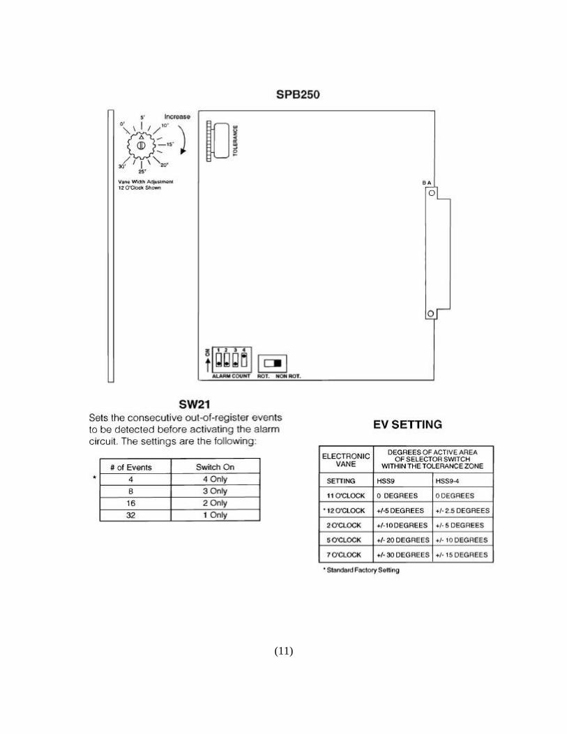
(11)
MODEL 200/250 INTERNAL ADJUSTMENTS Motor Type and Length Timing
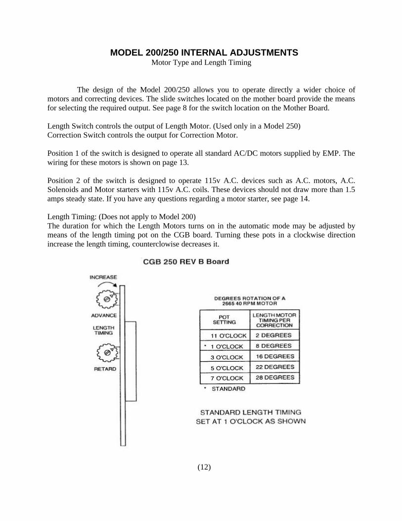
The design of the Model 200/250 allows you to operate directly a wider choice of motors and correcting devices. The slide switches located on the mother board provide the means for selecting the required output. See page 8 for the switch location on the Mother Board. Length Switch controls the output of Length Motor. (Used only in a Model 250) Correction Switch controls the output for Correction Motor. Position 1 of the switch is designed to operate all standard AC/DC motors supplied by EMP. The wiring for these motors is shown on page 13. Position 2 of the switch is designed to operate 115v A.C. devices such as A.C. motors, A.C. Solenoids and Motor starters with 115v A.C. coils. These devices should not draw more than 1.5 amps steady state. If you have any questions regarding a motor starter, see page 14. Length Timing: (Does not apply to Model 200) The duration for which the Length Motors turns on in the automatic mode may be adjusted by means of the length timing pot on the CGB board. Turning these pots in a clockwise direction increase the length timing, counterclowise decreases it.
(12)
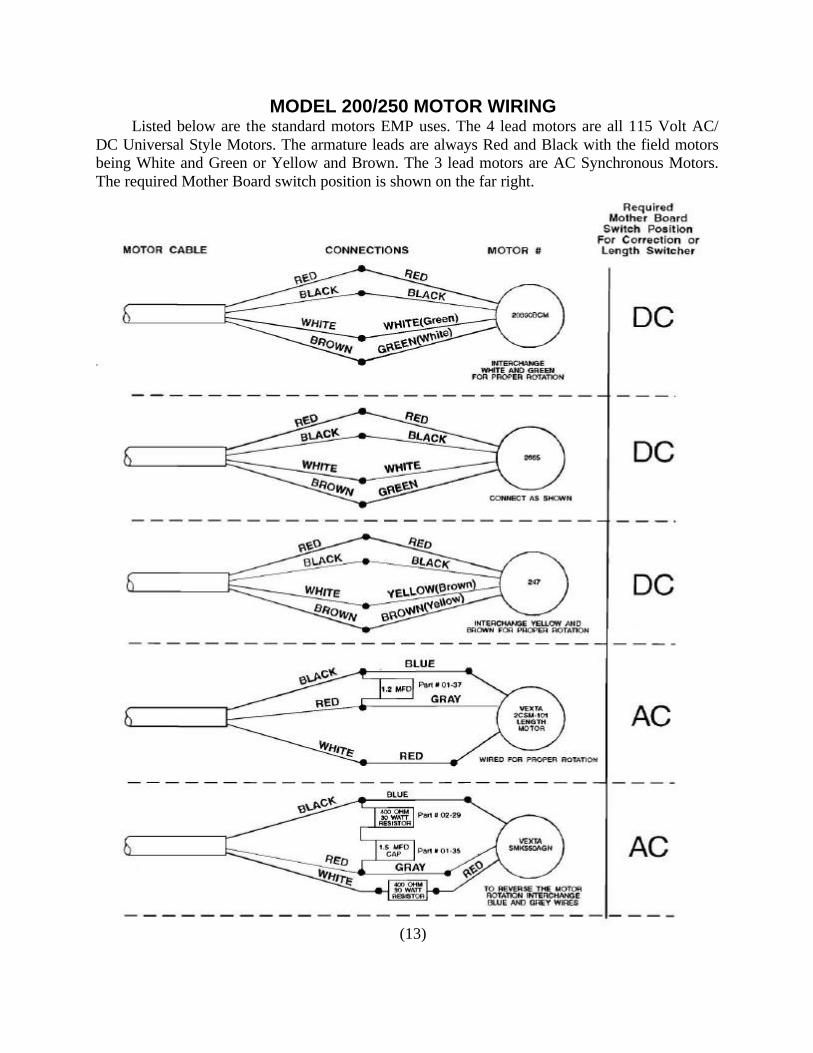
MODEL 200/250 MOTOR WIRING Listed below are the standard motors EMP uses. The 4 lead motors are all 115 Volt AC/ DC Universal Style Motors. The armature leads are always Red and Black with the field motors being White and Green or Yellow and Brown. The 3 lead motors are AC Synchronous Motors. The required Mother Board switch position is shown on the far right.
(13)

MOTOR STARTER WIRING
In applications where the existing correction motor is; A. Rated above 1/10 H.P. B. Draws more than 3 full load amps. C. Not a 120vac single phase motor. EMP recommends the use of an across the line motor starter that is mechanically interlocked. Atypical starter would be Allen-Bradley Bulletin 505 style with 120VAC coils. These starters can be operated by the Model 250 directly. The appropriate overload heaters must be selected to match the motors characteristics. For other motor types, please consult EMP Engineering Division. 1. For Correction Starter Set Mother Board SW9 to AC 2. For Length Starter, Set Mother Board SW8 to AC 3. Connect Red to One Coil 4. Connect Black to Other Coil 5. Connect Remaining Terminals of Both Coils to White 6. Connect 0.1 MFD.400V Capacitors Across Coils as Shown 7. Deadened Brown Wire 8. To Reverse Action Interchange Red and Black Wires
(14)
SYSTEM CHECKOUT EMP recommends the Model 200/250 System be checked at the initial installation and at any time a registration problem is experienced. This checkout will help to isolate the faulty component. To correct the problem, refer to the “troubleshooting guide.” 1. With the machine’s main drive off, set the Controller’s Front Panel settings to: Sensitivity - “3” Light-Dark Switch - Dark Advance and Retard Timing - “2” Correction Motor On-Off - On Length Motor On-Off - Off 2. Press the Retard Jog Switch. The Retard indicator lamp will light. The draw rollers will retard the web.* 3. Push the Advance Jog Switch. The Advance indicator lamp will light. The draw rollers will advance the web. 4. Rotate the outer dial of the Selector Switch so that the indicator arrow points to the advance flag. The green advance LED on the front panel will be on. 5. Pass a mark under the Scanner beam, the pick-up LED must flash. 6. The advance indicator lamp will light. The draw rollers will advance the web slightly. 7. Repeat steps 4, 5 and 6 in the retard mode. 8. Increase both the Advance and retard time setting on the front panel to “10”. 9. Repeat steps 4, 5 and 6 in both the advance and retard modes. 10. This completes the system checkout. *On machines where the registration system controls the knife, the knife should advance when the retard jog button is pushed, and retard when the advance button is pushed.
(15)

SETUP & OPERATING PROCEDURE
Setup A. Changing Jobs to a new Print Pattern. 1. Turn the Power ON, the Correction Motor On/Off to Off, the Length Motor On-Off to On. The Length Motor cannot be jogged while the Correction Motor is turned on.
2. Test run the machine to obtain the correct job length. You should be able to make (10) consecutive cuts with the cut position at the same point on the print. On model 250 Controllers the length may be adjusted using the ADVANCE or RETARD JOG BUTTONS. Pushing the advance jog button increases the length, while pushing the retard decreases it. Turn the CORRECTION MOTOR to “ON.” For Model 200 Controllers, the Length Motor must be adjusted manually. 3. Check that the scanner beam is properly aligned and focused along the registration mark path. The scanner lens should be 3/8 to ½ of an inch from the web. (See Fig. 1) pp. 18 4. Set the light/dark switch to the proper mode on the control panel 5. To set the sensitivity control, pass a sample of the web containing the registration mark through the Scanner beam while observing the pickup indicator LED on the Control Panel. Advanced the sensitivity from zero until the register mark generates a flash of the pickup indicator. Increase the sensitivity at least half a number for crisp detection. 6. Using the existing MACHINE’S JOG button, rotate the knife, stopping at a point barely prior to the cutting action. (See Fig. 1) pp.18 7. Jog the web using the Jog Switch on the Controller’s Front Panel until the desired cut position has been reached. 8. Using the MACHINE JOG, jog the machine feed. Move the web until the leading edge of the next register mark in under the scanner. (See Fig. 2) pp.18 9. Loosen the top lock knob on the Selector Switch and rotate the outer cycle dial of the Selector Switch until the arrow on the indicator dial points to the “0” between the advance and retard areas. Retighten to the lock knob. (See Fig. 3) pp.18 10. Loosen the outer lock knob on the front of the cycle dial and turn the inner adjustment knob so as to leave a slight opening between the live areas. NOTE: Too large an opening affects cut-off tolerance. 11. Set the advance and retard time knob to “4.” 12. You have now completed the static set-up of the machine. Now run the machine as normal and do the following:
(16)

SETUP & OPERATING PROCEDURE 13. Observe the Motor Indicator lamps. If red or green lights predominate, the Length Motor will automatically adjust the Zero Max or PIV control, correcting the cut-off length. 14. Having achieved alternating red and green flashes, adjust the advance and retard correction times until the corrections settle down to a minimum necessary to maintain registration. 15. Adjustment of the “Dead Area Adjustment” on the Selector Switch will increase the “Dead Area” between the advance and retard “Live” areas. The closer the flags are together the harder the system will work to obtain exact registration. The further apart they are, the greater the “Dead Area” will be, which allows the cut-off to drift back and forth slightly. This in turn allows the unit to work a little easier. The correct setting varies from job to job and can be found by trial and error. 16. When the machine is running but not at the desired cut off position, the selector switch must be adjusted. The Cycle Dial when rotated slowly will reposition the cutoff point to any position on the web. The Cycle Dial had PRINT ADJUST BACK or FORWARD arrows to assist you to adjust the web to its proper position. It is important that the cycle dial be repositioned slowly to allow the system to follow the desired change in web position without leaving registration control. Setup B. Changing rolls with the same print pattern. 1. Using the existing MACHINE’S JOG button, rotate the knife stopping at a point barely
before the cutting action. 2. Jog the web using the Jog Switch on the Model 250 Front Panel until the desired cut
position has been reached. 3. You have now completed the static set-up of the machine. Now run the machine as
normal and do the following: 4. Observe the Motor indicator lamps. If red or green lights’ predominate, the Length Motor
will automatically adjust the Zero Max or PIV control, correcting the cut-off length. 5. Certain webs exhibit large length changes from roll to roll. On these webs it way be
necessary to rest the length before running the toll. To do this, turn the correction motor off and test run the machines using the ADVANCE or RETARD JOG BUTTONS to obtain the correct job length. You should be able to make 10 consecutive cuts with the cut position at the same point on the print. Turn the CORRECTION MOTOR TO “ON,” and repeat steps 1 through 3.
(17)

(18)

TROUBLESHOOTING GUIDE Before troubleshooting the system, we recommend you perform the system checkout on Page 15. 1. No Power to the Controller A. Check for 117V AC 60 Hz to the Controller. B. The Model 200/250 is equipped with a safety cut out feature. If the front panel is not
securely closed, there will be no AC power to the unit. C. Change the 5A. slo-blo fuse on front panel.
2. No Scanner “pickup” A. Check the sensitivity setting and the position on the light/dark switch. B. Inspect scanner cable and connector for physical damage. C. Check for correct focus. The scanner is in focus when the lens is 3/8 to ½ of an inch from
the web. D. Replace the bulb. Use only No. 19 bulbs. E. Check if the scanner bulb is illuminated. If not, check for 12V DC at the bulb terminals.
Consult EMP engineering if this in not present. F. Replace Scanner. G. Replace I.C. 12 (LM124) on the SPB REV.A Board.
or U6 (LM124) on SPB REV B. Board H. Replace SPB Board.
3. No Selector Switch LED Indication. A. Disconnect selector switch cable, both LED’s should be on. If one or both LED’s remain
off, replace CGB Board. B. If both LED’s are on, replace the selector switch optics, or the entire selector switch. The
LED’s should function normally. 4. Random Corrections and/or Random Pickup A. Check focal distance of scanner, light/dark switch position and scanner sensitivity setting. B. Check that the mark has a clear space on both sides. The criterion for this clear space is
spelled out on Page 7. C. Insufficient contrast between marks and background color can cause missed marks. D. If the web is glossy use a foil adaptor on the scanner, or if a foil adaptor is not available
tilt the scanner to an angle of 30 degrees. E. Do not allow fluorescent light to shine directly on the web under the scanner as this may
cause unwanted pickup. F. If the web “flutters” near the scanner, the scanner may respond to this. Try positioning the
scanner near or over a roller. G. Change motor brushes. H. AC supply voltages under 111V AC cause the scanner to “sense” random marks. Ensure
that correct line voltages are present even during “brown outs.”
(19)

TROUBLESHOOTING GUIDE I. Ensure phasing of the AC Hot and Neutral leads is correct. J. Make certain all grounds are secure and all connecting screws are tight. K. Excessive power line noise can cause random correction. Use a separate power line clear
of heavy equipment, solenoids, and thyristor driven circuits, or use a 250 VA isolation transformer. (Stancor GIS-250 or Triad-Utrad N55M).
L. Follow steps under #7 for static noise problems. 5. Varying Cut Off Positions A. Turn off registration system, and set Variator for correct length. If length tends to vary
with the correction system off, check the adjustment and mechanical condition of the machine. Check for worn gears, pulleys and sprockets, stretched and/or loose chains, etc. Check that the web is in good contact with the draw-roller, (no slippage).
B. Roll out two lengths of web side by side and compare the accuracy or the repeat length. C. Check that the registration mark is in register with the rest of the print, particularly if it
was imprinted. D. Reduce setting on timing pots found on the Front Panel to two. This assures we are not
over correcting. E. Check that the motors are phased properly for the correct direction. F. Review the steps outlined in step number four above, as random corrections would cause
variations in the cutoff position. 6. Correction or Length Motors Do Not Operate Correctly.
A. Check that Correction and Length Motor Switches, located on the mother board are set correctly.
B. Check the fuses on the relay board. F2 is for the Length Motor. F3 is for the Correction Motor. Replace if necessary, us only 3A slo-blo fuses. If fuse continue to blow, check with EMP Engineering.
C. Jog the motors, if the motor jog switch indicators do not illuminate, change the CGB. D. Check the motors by jogging in both the advance and retard direction. The solid state
relay board can be replaced. For no length motor action in advance: Replace IC 26 For no length motor action in retard: Replace IC 27 For no correction motor action in advance: Replace IC 24 For no correction motor action in retard: Replace IC 25
E. If the problem occurs in retard only, replace IC 22 and IC 23 on the CGB board. If the problem occurs in advance only, replace IC 20 and IC 21 on the CGB board.
(20)

TROUBLESHOOTING GUIDE
F. If the motors work on jog, but do not work on automatic, then check for pickup. See page 19 section 2 & 3.
G. Check the motor installation and cables. Before replacing any part check the AC power has been removed from the unit.
H. If you are using DC motors then bench check the motor as follows. Remove motor, Using an OHM Meter, check that there is no continuity between any of the leads and the frame. If there is, Replace the motor.
I. Twist the red and black leads together, there should be no continuity between the pair of leads and any of the other two leads. If there is, replace the motor.
J. Check that there is continuity across the red and black leads even while the armature shaft is being turned. Reject the motor if there are “dead spots”. Check the brushes and commutator shafts.
7. Random Errors due to Static or Electronic Noise.
A. Check AC power for proper phasing. Check the AC grounding and use isolation trans- former if necessary.
B. Shut off static eliminators briefly to see if the problem stops. If random phase errors stop check controller cable are not bundled with cable from the static eliminator.
C. Replace the motor brushes. D. Turn sensitivity to zero. If pickup continues check that the scanner is not in electrical
contact with the machine. Consult EMP for a fiber mount if necessary. E. If there are solenoids on the machine, it may be necessary to suppress them by replacing
capacitors across their terminals.
(21)

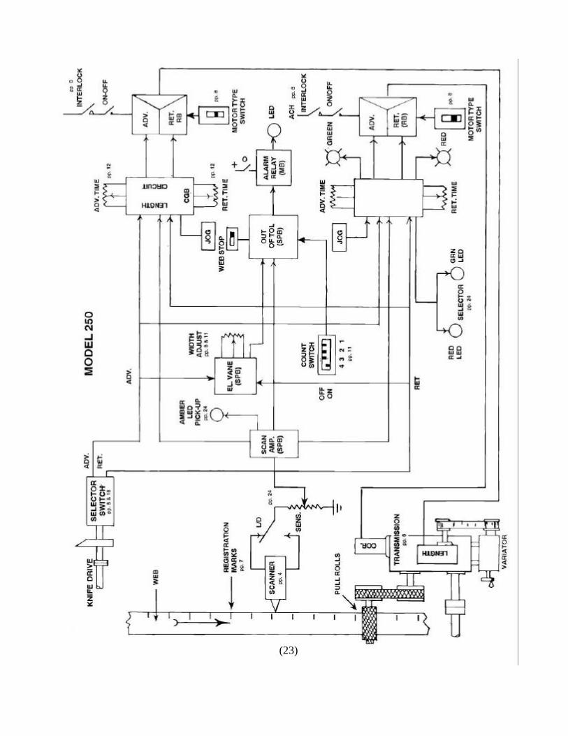
CIRCUIT DESCRIPTION Retard and Advance position signals are generated by the Selector Switch’s optics.
These signals are processed by the CGB Board. The processing of these signals is verified by the Advance and Retard LED’s. The scanner senses the registration mark, and sends a signal to the SPB Board. This signal is conditioned by the SPB Board and is applied to the EV circuit and to the CGB Board. The existence of the mark signal can be verified by the flashing of the scanner pickup LED, located on the Front Panel. If the web is in register then the mark signal will appear when neither a retard nor an advance signal is present. Should the mark appear while an advance or retard signal is present, a correction signal will be generated because the CGB Board will determine that an advance or retard correction is necessary. The correction is applied to the RB Board, where it will drive the solid state relays which energize both the Correction and Length motors. The correction signal can be verified by the flashing of either the advance or retard jog indicator lamps. The Correction Motor’s advance and Retard timing may be varied by Front Panel timing knobs. The Length Motor timing is set by adjustments on the CGB Board. The Solid State Relays are of zero crossover type which help minimize line transients. The use of solid state relays allow a wider range of motors, solenoids, and motor starters etc. to be used with the Model 200/250.
The out of tolerance circuit works as follows; The EV circuit on the SPB Board receives the Advance and Retard signals from the selector switch. The EV Circuit establishes a tolerance area centered on the advance and retard areas of the Selector Switch. The width of this tolerance are may be adjusted using the EV adjustment pot of the SPB Board. If a mark should occur in this area, then no further action is taken. If no mark occurs in this area, then the electronics recognizes this as an out of tolerance event. After a present number of such events the alarm is energized, and will stay turned on. The number of consecutive out of tolerance events before an alarm is energized can be preset at 4, 8, 16 or 32 by means of a switch SW21 on the SPB Board. (See page 11)
(22)
(23)
(24)
(25)

WIRE CONNECTIONS
Power Cord Scanner A - Black - AC Hot A - Green B - Green - Gnd (Frame) B - Black C - White - AC Neutral C - White D - Orange Selector Switch E - Red A - Black Brown - No Connections, Spares B - Green Yellow - No Connections, Spares C - Shield Blue - No Connections, Spares D - White E – Red Alarms Motor Cord Green - Normally Closed A - Brown White - Common B - White Black - Normally Open C - Red D - Black
WARRANTY
We guarantee to replace, at our option, repair any products of therefore, which are found to be defective in material or workmanship, within one year from the date of shipment, except relays or motors, which are guaranteed for ninety days. Our obligation with respect to such products or parts, shall be limited to replacement or repair, F.O.B. Hauppauge, New York. In no event shall we be held liable for consequential or special damages or for transportation, installation, adjustment, or other expenses which may arise in connection with such products or parts.
(26) Revision: January 6, 2004


