Model 2285 EtherBITS™UniversalSingle-Port Device Server Getting Started Guide Sales Office: +1 (301) 975-1000 Technical Support: +1 (301) 975-1007 E-mail: [email protected]WWW: www.patton.com Document Number: 08313U2-001 Rev. B Part Number: 07M2285-UM Revised: October 8, 2007 Important This is a Class A device and is intended for use in a light industrial environment. It is not intended nor approved for use in an industrial or residential environment.
This is a Class A device and is intended for use in a light industrial environment. It is not intended nor approved for use in an industrial or residential environment.
4 Serial port configuration ............................................................................................................................... 44
5 System administration................................................................................................................................... 71
6 System statistics............................................................................................................................................. 80
8 Contacting Patton for assistance ................................................................................................................... 90
A Compliance information .............................................................................................................................. 93
B Specifications ................................................................................................................................................ 95
C Cable Recommendations .............................................................................................................................. 99
D Configuration files ..................................................................................................................................... 104
E Well-known port numbers ......................................................................................................................... 107
F Guide to the Bios menu program ............................................................................................................... 109
G Using Model 2285 with Serial/IP ............................................................................................................... 116
Contents
Summary Table of Contents ........................................................................................................................... 3
List of Figures ................................................................................................................................................. 8
List of Tables ................................................................................................................................................ 10
About this guide ........................................................................................................................................... 11
Safety when working with electricity ...............................................................................................................12
General observations .......................................................................................................................................13
Typographical conventions used in this document................................................................................................ 14
General conventions .......................................................................................................................................14
MAC address ..................................................................................................................................................17
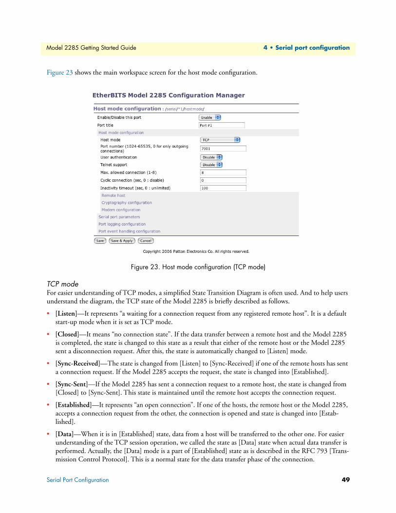
Unpacking the Model 2285...................................................................................................................................20
Controls and indicators .........................................................................................................................................20
Connecting the hardware.......................................................................................................................................22
Connecting to the network .............................................................................................................................23
Connecting to the device ................................................................................................................................23
Connecting power ...........................................................................................................................................23
Accessing the System Console................................................................................................................................24
Using the System console ................................................................................................................................24
Using remote console ......................................................................................................................................25
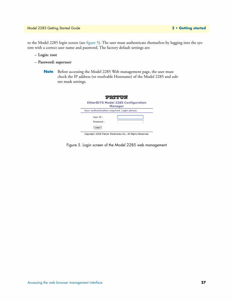
Accessing the web browser management interface..................................................................................................26
IP configuration ....................................................................................................................................................30
Using a Static IP Address ................................................................................................................................30
IP address ..................................................................................................................................................31
Primary and Secondary DNS ....................................................................................................................31
Using DHCP ..................................................................................................................................................31
MIB-II System objects Configuration .............................................................................................................33
Access Control Configuration .........................................................................................................................34
Management using SNMP ..............................................................................................................................35
Dynamic DNS Configuration ...............................................................................................................................35
IP Filtering ............................................................................................................................................................38
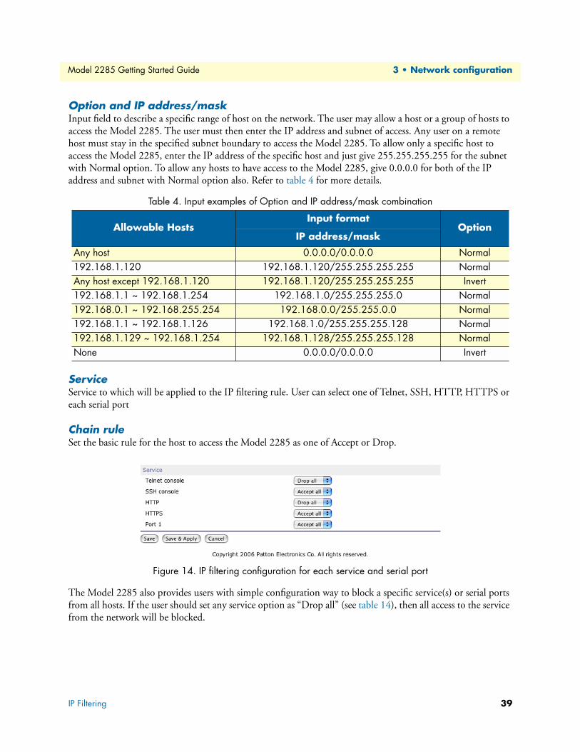
Option and IP address/mask ...........................................................................................................................39
Service ............................................................................................................................................................39
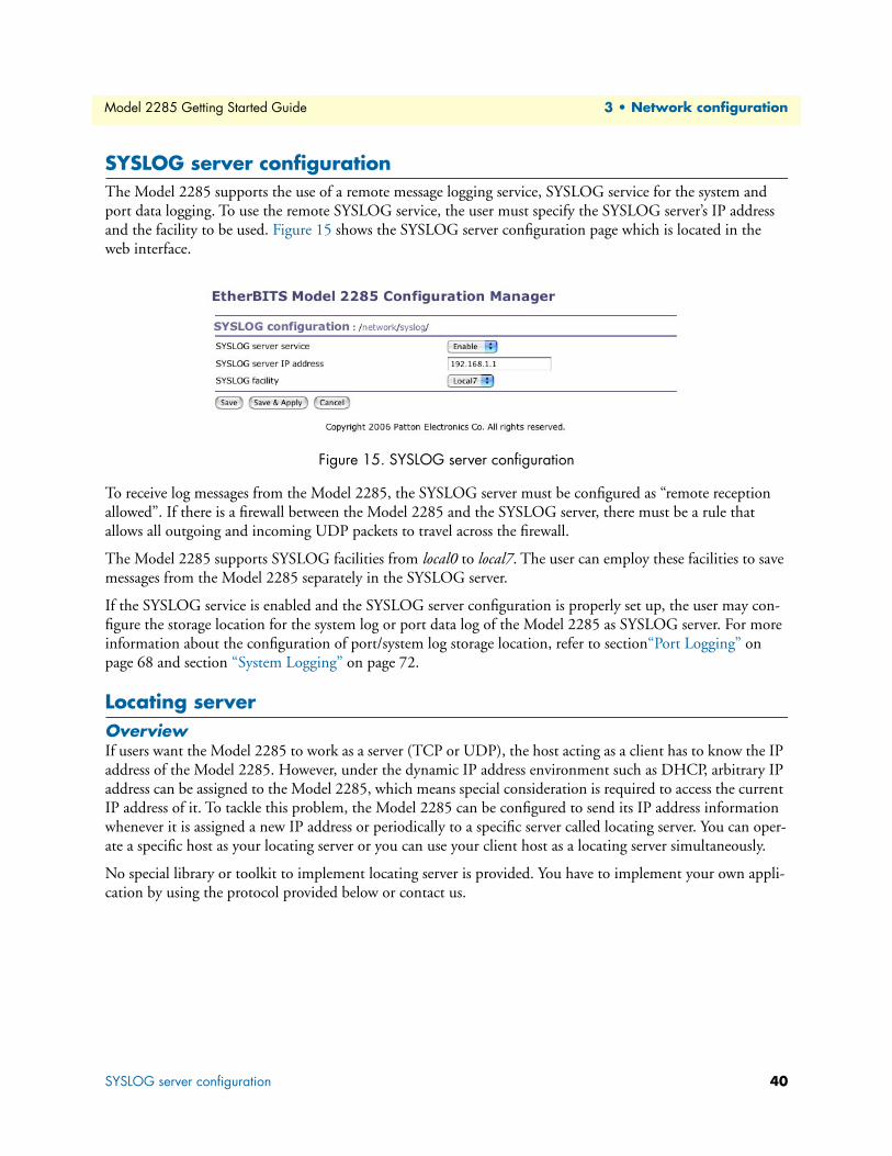
SYSLOG server configuration................................................................................................................................40
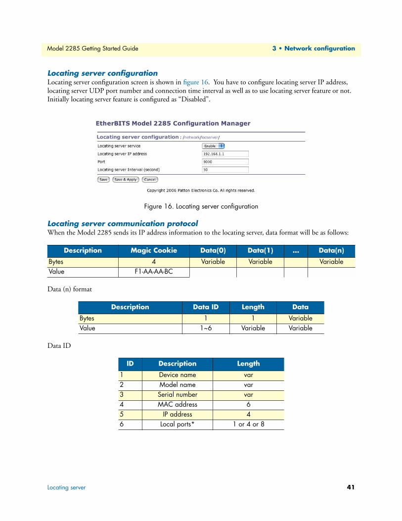
Locating server configuration ..........................................................................................................................41
Locating server communication protocol ........................................................................................................41
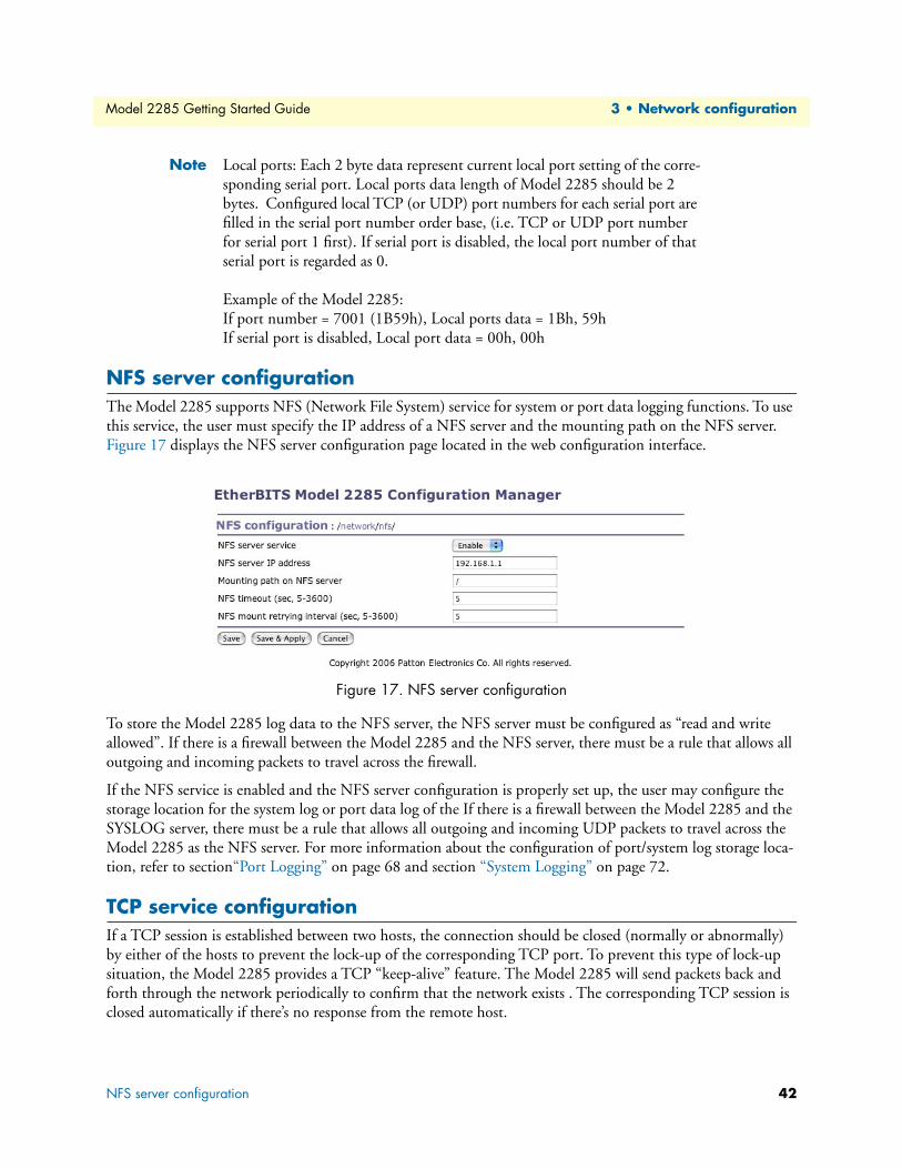
NFS server configuration.......................................................................................................................................42
TCP service configuration .....................................................................................................................................42
4 Serial port configuration ............................................................................................................................... 44
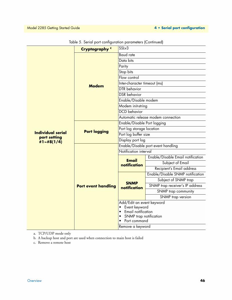
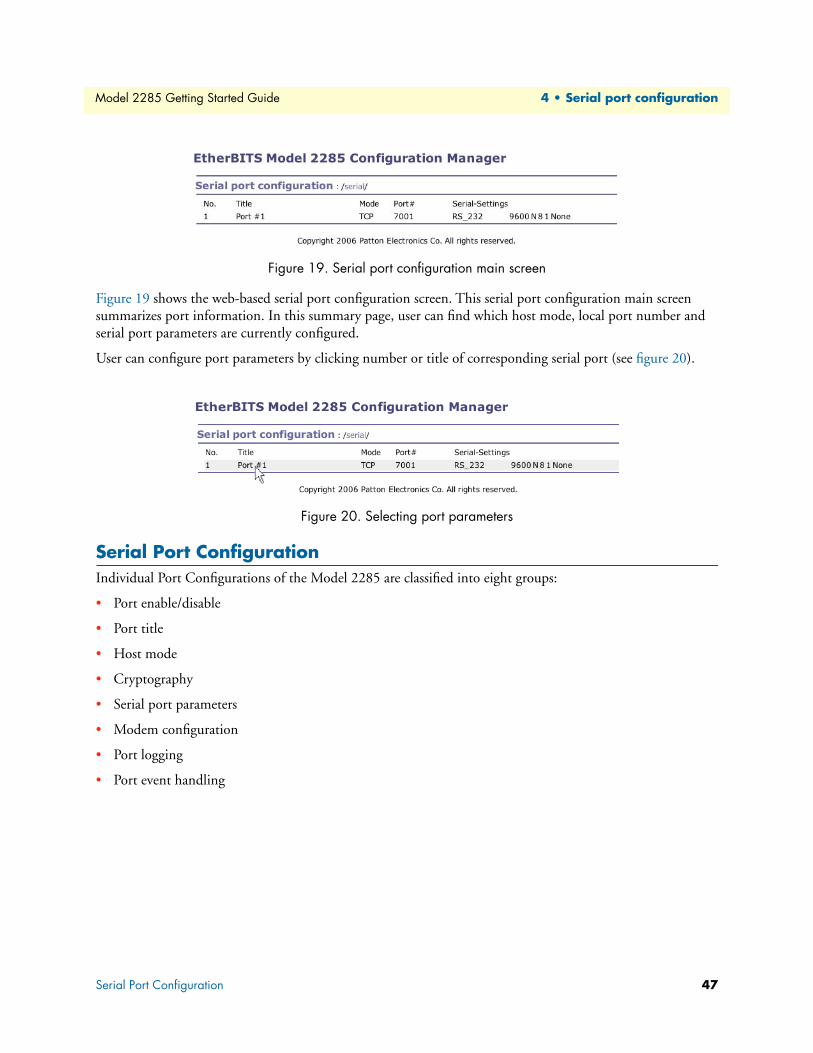
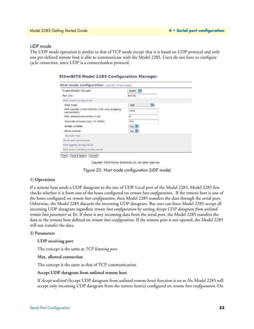
Serial Port Configuration.......................................................................................................................................47
Port Enable/Disable ........................................................................................................................................48
Port Title ........................................................................................................................................................48
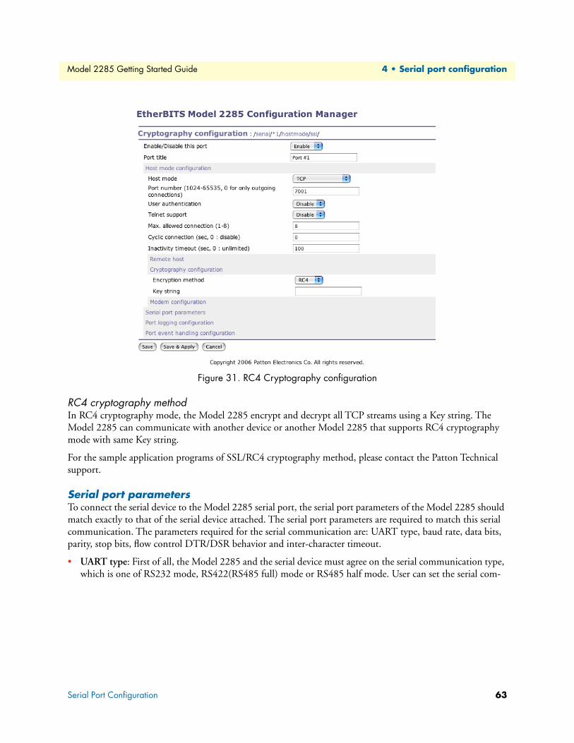
Serial port parameters ......................................................................................................................................63
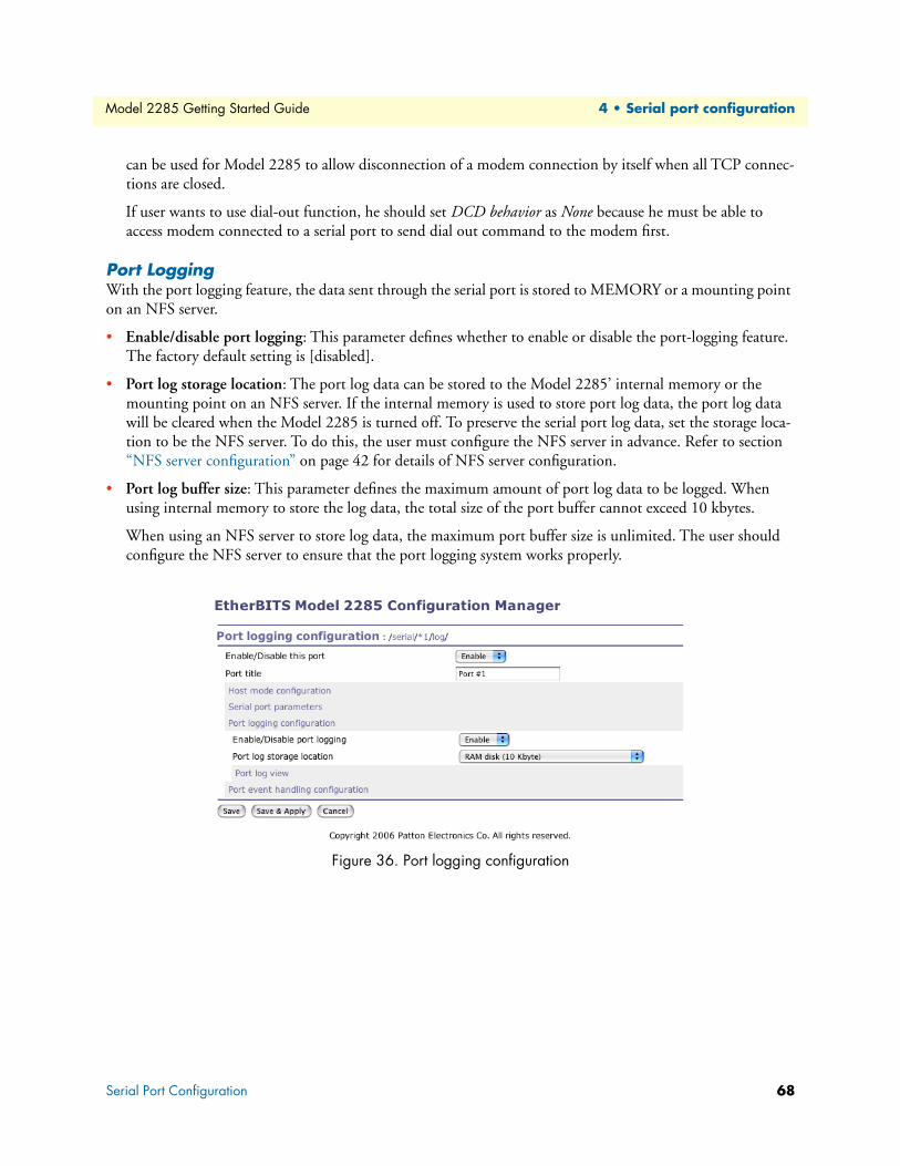
Port Logging ...................................................................................................................................................68
Port event handling configurations .................................................................................................................69
5 System administration................................................................................................................................... 71
System Logging .....................................................................................................................................................72
Device Name Configuration..................................................................................................................................74
Date and Time Settings .........................................................................................................................................74
User administration ...............................................................................................................................................79
6 System statistics............................................................................................................................................. 80
Serial Ports Statistics ..............................................................................................................................................81
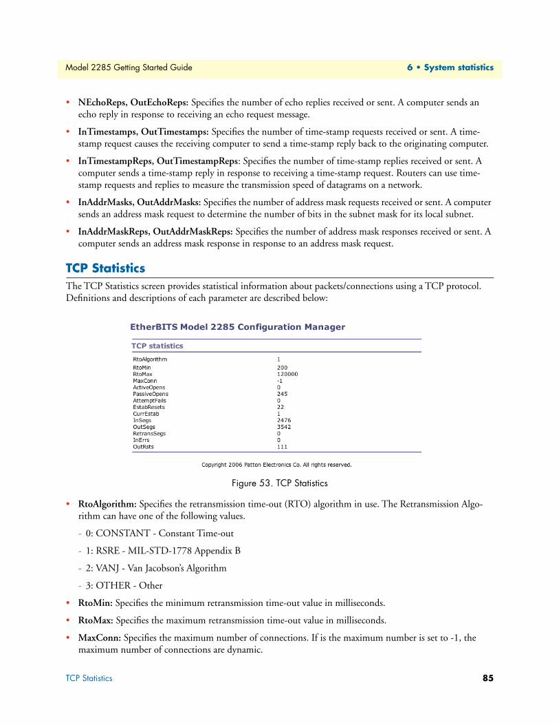
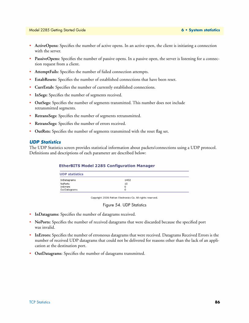
IP Statistics .....................................................................................................................................................82
Supported Linux Utilities ......................................................................................................................................88
File and disk utils ............................................................................................................................................88
System utilities ................................................................................................................................................88
Out-of-warranty service .............................................................................................................................92
Returns for credit ......................................................................................................................................92
Return for credit policy .............................................................................................................................92
A Compliance information .............................................................................................................................. 93
Radio and TV Interference (FCC Part 15) ............................................................................................................94
CE Declaration of Conformity ..............................................................................................................................94
Authorized European Representative .....................................................................................................................94
B Specifications ................................................................................................................................................ 95
Serial interface .......................................................................................................................................................96
Power ....................................................................................................................................................................97
C Cable Recommendations .............................................................................................................................. 99
Console and Serial port pin-outs..........................................................................................................................101
Serial wiring diagram...........................................................................................................................................102
RS-232 serial wiring diagram ........................................................................................................................102
RS-422/485 serial wiring diagram .................................................................................................................103
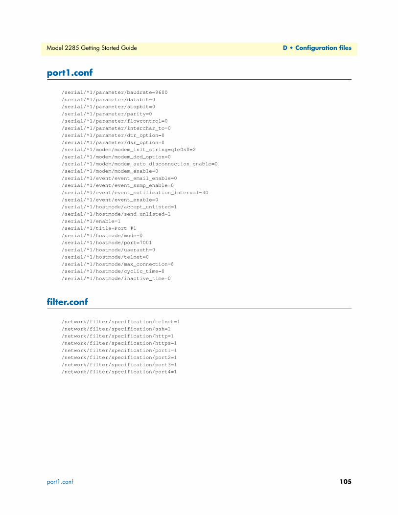
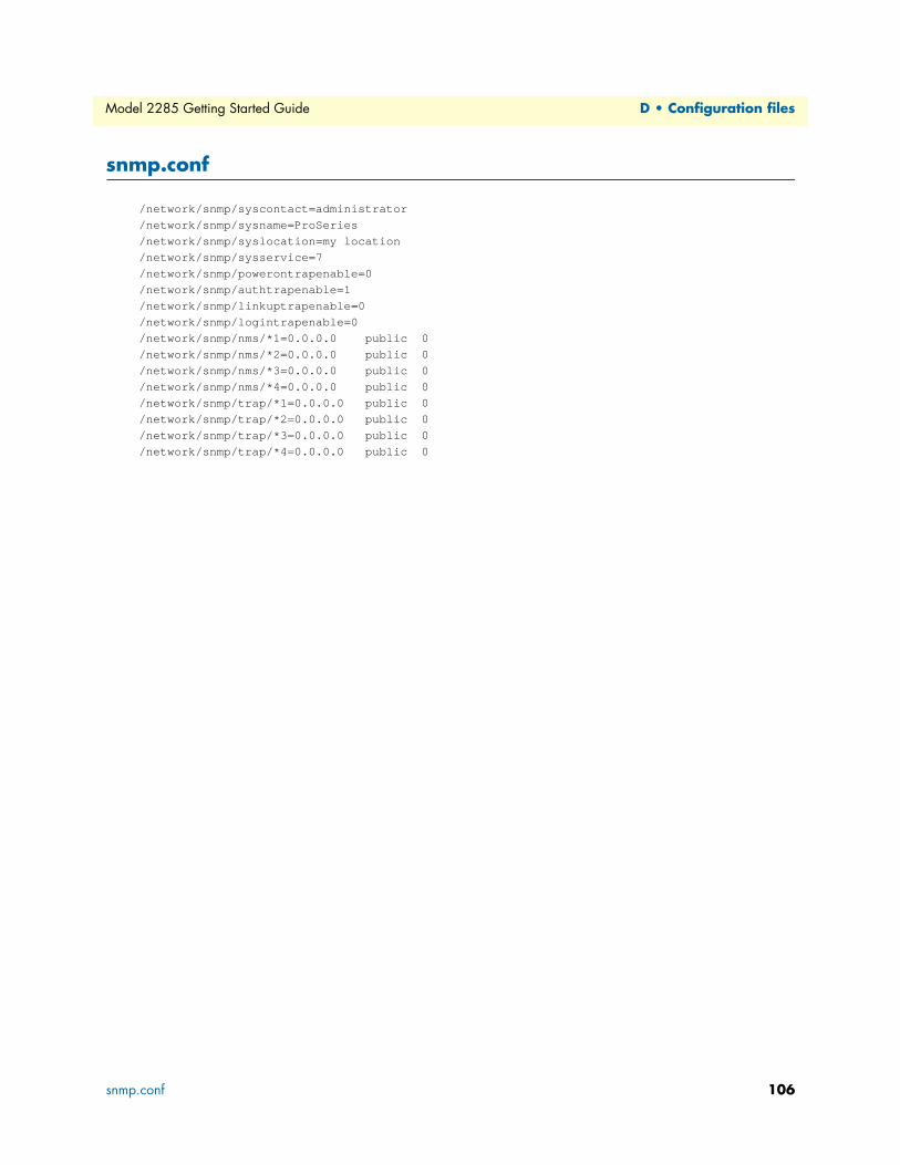
D Configuration files ..................................................................................................................................... 104
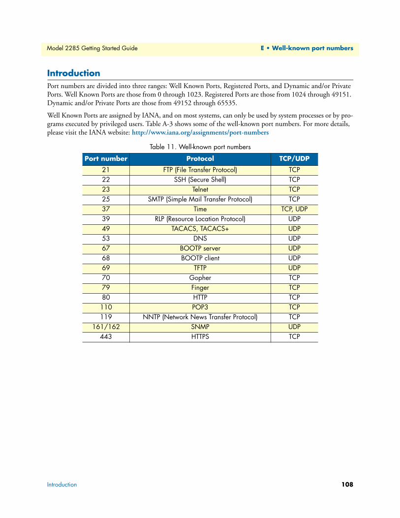
E Well-known port numbers ......................................................................................................................... 107
Main menu..........................................................................................................................................................110
RTC configuration menu ....................................................................................................................................110
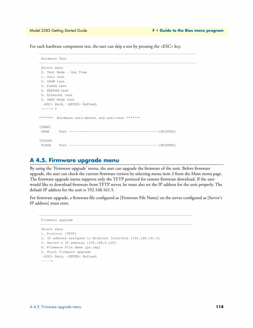
Hardware test menu ............................................................................................................................................111
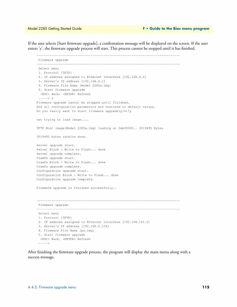
A 4.5. Firmware upgrade menu ...........................................................................................................................114
G Using Model 2285 with Serial/IP ............................................................................................................... 116
Model 2285 vs. Serial/IP options.........................................................................................................................117
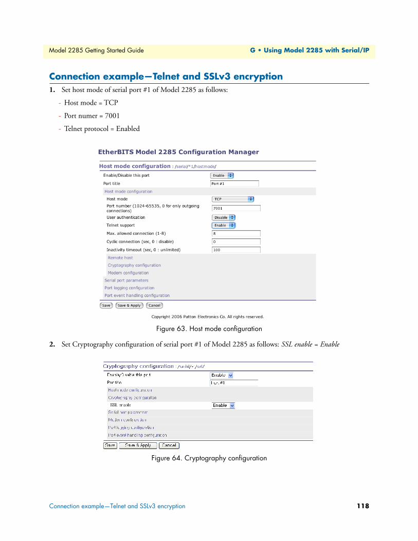
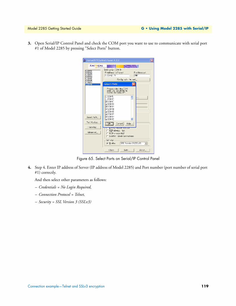
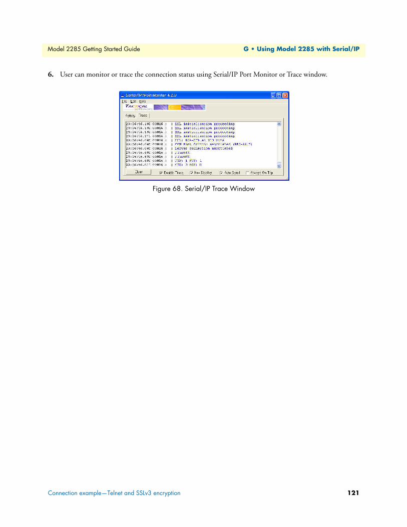
Connection example—Telnet and SSLv3 encryption ..........................................................................................118
About this guideThis guide describes installing and configuring a Patton Electronics Model 2285 EtherBITS™ Universal Sin-
gle-Port Device Server. By the time you are finished with this guide, your device server will be fully connected
and able to transfer data.
AudienceThis guide is intended for the following users:
Operators
Installers
Maintenance technicians
StructureThis guide contains the following chapters and appendices:
Chapter 1 on page 15 provides information about device server features and capabilities
Chapter 2 on page 19 describes installing the device server
Chapter 3 on page 29 describes how to set up the network configuration
Chapter 4 on page 44 describes configuring the serial port
Chapter 5 on page 71 describes configuring the system administration
Chapter 6 on page 80 describes using system statistics
Chapter 7 on page 87 describes the CLI
Chapter 8 on page 90 contains information on contacting Patton technical support for assistance
Appendix A on page 93 contains compliance information for the Model 2285 device server
Appendix B on page 95 contains specifications for the device server
Appendix C on page 99 provides cable recommendations
Appendix D on page 104 describes the configuration files
Appendix E on page 107 lists well-known port numbers
Appendix F on page 109 provides a guide to the Bios menu program
Appendix G on page 116 describes using the Model 2285 with Serial/IP
For best results, read the contents of this guide before you install the device server.
11
Model 2285 Getting Started Guide
About this guide
PrecautionsNotes, cautions, and warnings, which have the following meanings, are used throughout this guide to help you
become aware of potential problems. Warnings are intended to prevent safety hazards that could result in per-
sonal injury. Cautions are intended to prevent situations that could result in property damage or
impaired functioning.
Note A note presents additional information or interesting sidelights.
Safety when working with electricity
The alert symbol and IMPORTANT heading calls attention to important information.
The alert symbol and CAUTION heading indicate a potential haz-ard. Strictly follow the instructions to avoid property damage.
The shock hazard symbol and CAUTION heading indicate a potential electric shock hazard. Strictly follow the instructions to avoid property damage caused by electric shock.
The alert symbol and WARNING heading indicate a potential safety hazard. Strictly follow the warning instructions to avoid personal injury.
The shock hazard symbol and WARNING heading indicate a potential electric shock hazard. Strictly follow the warning instructions to avoid injury caused by electric shock.
Do not work on the system or connect or disconnect cables during periods of lightning activity.
For units with an external power adapter, the adapter shall be a listed Lim-ited Power Source.
IMPORTA
CAUTIO
CAUTIO
WARNIN
WARNIN
WARNIN
WARNIN
12
Model 2285 Getting Started Guide
About this guide
General observationsClean the case with a soft slightly moist anti-static cloth
Place the unit on a flat surface and ensure free air circulation
Avoid exposing the unit to direct sunlight and other heat sources
Protect the unit from moisture, vapors, and corrosive liquids
Factory default parametersModel 2285 EtherBITS Universal Single-Port Device Server have the following factory default parameters.
Ethernet IP address: 192.168.161.5
Login: superuser
Password: superuser
Static IP address
Filter: “All services and ports are accessible from any host.”
Serial port: 9600 data rate , 8-bits, no parity, 1 stop bit, no flow control
Hazardous network voltages are present in WAN ports regardless of whether power to the unit is ON or OFF. To avoid electric shock, use caution when near WAN ports. When detaching the cables, detach the end away from the device first.
This device contains no user serviceable parts. The equipment shall be returned to Patton Electronics for repairs, or repaired by qualified service personnel.
In accordance with the requirements of council directive 2002/96/EC on Waste of Electrical and Electronic Equipment (WEEE), ensure that at end-of-life you separate this product from other waste and scrap and deliver to the WEEE collection system in your country for recycling.
WARNIN
WARNIN
13
Model 2285 Getting Started Guide
About this guide
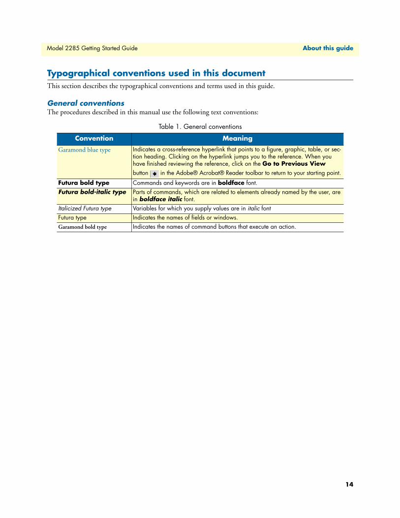
Typographical conventions used in this documentThis section describes the typographical conventions and terms used in this guide.
General conventionsThe procedures described in this manual use the following text conventions:
Table 1. General conventions
Convention Meaning
Garamond blue type Indicates a cross-reference hyperlink that points to a figure, graphic, table, or sec-tion heading. Clicking on the hyperlink jumps you to the reference. When you have finished reviewing the reference, click on the Go to Previous View button in the Adobe® Acrobat® Reader toolbar to return to your starting point.
Futura bold type Commands and keywords are in boldface font.Futura bold-italic type Parts of commands, which are related to elements already named by the user, are
in boldface italic font.Italicized Futura type Variables for which you supply values are in italic fontFutura type Indicates the names of fields or windows.Garamond bold type Indicates the names of command buttons that execute an action.
MAC address ..................................................................................................................................................17
IntroductionThe Model 2285 EtherBITS Universal Single-Port Device Server makes your legacy serial devices manageable
by an industry-standard Ethernet network. Based on open network protocols such as TCP/IP and UDP, it
gives you ultimate flexibility to your serial devices.
With the rich broadband network connectivity protocols such as DHCP and Dynamic DNS, you can manage
legacy serial devices over broadband Internet by using DSL or cable modem connection. The built-in Dynamic
DNS protocol of the Model 2285 enables you to access the serial devices with their own domain names.
The Model 2285 also provides you with the system management functionality of system status display, firm-
ware upgrade, remote reset and system log display by using various ways such as telnet, SSH, serial console port
or web.
You can configure and administrate the Model 2285, with the management functions of status monitor,
remote reset, error log monitor and firmware upgrade by using Telnet and serial console port under the pass-
word secured support.
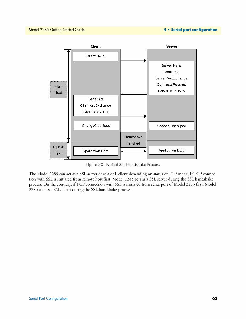
For critical applications of secure data communication, the Model 2285 supports SSLv3 for data encryption.
In addition, IP address filtering function is provided for protecting unintentional data streams to be transmit-
ted to the Model 2285.
Typical application areas of the Model 2285 are:
• Industrial automation
• Network management
• Retail/Point of sale
• Remote metering
• Remote display
• Building automation
• Security/Access control systems
• General data acquisition application
• Medical application
The Model 2285 gives you ideal remote management capability of control, monitoring, diagnosis and data
gathering over RS232/422/485 serial devices.
Note This manual assumes user knowledge of Internetworking protocols and
serial communications
Introduction 16
Model 2285 Getting Started Guide
1 • Overview
GlossaryThis section defines commonly used terms in this manual. These terms are related to Internetworking, and
defined in regards to their use with Model 2285.
MAC addressOn a local area network or other network, the MAC (Media Access Control) address is the computer’s unique
hardware number. (On an Ethernet LAN, it is the same as the Ethernet address.)
It is a unique 12-digit hardware number, which is composed of 6-digit OUI (Organization Unique Identifier)
number and 6-digit hardware identifier number. The MAC address can be found on the bottom of the
original package.
HostA user’s computer connected to the network
Internet protocol specifications define host as any computer that has full two-way access to other computers on
the Internet. A host will have a specific local or host number that, together with the network number, forms its
unique IP address.
SessionA series of interactions between two communication end points that occur during the span of a
single connection
Typically, one end point requests a connection with another specified end point. If the specified end point
replies, and agrees to the connection, the end points then take turns exchanging commands and data (talking to
each other). The session begins when the connection is established at both ends and terminates when the con-
nection is ended.
Client/ServerClient/server describes the relationship between two computer programs in which one program, the client,
makes a service request from another program, the server, which fulfills the request.
A server is a computer program that provides services to other computer programs on one or many computers.
The client is the requesting program or user in a client/server relationship. For example, the user of a Web
browser is effectively making client requests for pages from servers all over the Web. The browser itself is a cli-
ent in its relationship with the computer that is getting and returning the requested HTML file. The computer
handling the request and sending back the HTML file is a server.
Glossary 17
Model 2285 Getting Started Guide 1 • Overview
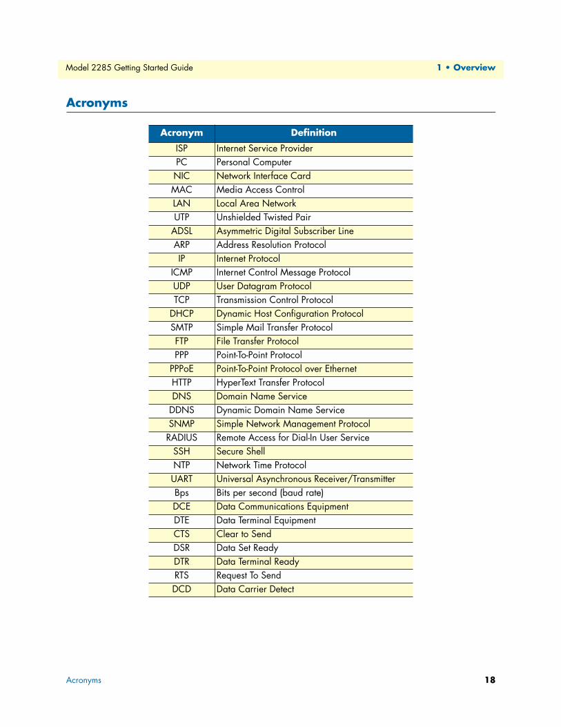
Acronyms
Acronym Definition
ISP Internet Service ProviderPC Personal ComputerNIC Network Interface CardMAC Media Access ControlLAN Local Area NetworkUTP Unshielded Twisted Pair
ADSL Asymmetric Digital Subscriber LineARP Address Resolution ProtocolIP Internet Protocol
ICMP Internet Control Message ProtocolUDP User Datagram ProtocolTCP Transmission Control Protocol
DHCP Dynamic Host Configuration ProtocolSMTP Simple Mail Transfer ProtocolFTP File Transfer ProtocolPPP Point-To-Point Protocol
PPPoE Point-To-Point Protocol over EthernetHTTP HyperText Transfer ProtocolDNS Domain Name Service
DDNS Dynamic Domain Name ServiceSNMP Simple Network Management ProtocolRADIUS Remote Access for Dial-In User Service
SSH Secure ShellNTP Network Time ProtocolUART Universal Asynchronous Receiver/TransmitterBps Bits per second (baud rate)DCE Data Communications EquipmentDTE Data Terminal EquipmentCTS Clear to SendDSR Data Set ReadyDTR Data Terminal ReadyRTS Request To SendDCD Data Carrier Detect
Unpacking the Model 2285...................................................................................................................................20
Controls and indicators .........................................................................................................................................20
Connecting the hardware.......................................................................................................................................22
Connecting to the network .............................................................................................................................23
Connecting to the device ................................................................................................................................23
Connecting power ...........................................................................................................................................23
Accessing the System Console................................................................................................................................24
Using the System console ................................................................................................................................24
Using remote console ......................................................................................................................................25
Accessing the web browser management interface..................................................................................................26
19
Model 2285 Getting Started Guide 2 • Getting started
IntroductionThis chapter describes how to set up and configure the Model 2285.
• “Unpacking the Model 2285”—lists the contents of the device server’s shipping container
• “Controls and indicators”—Explains the layout of the Model 2285 controls and LED indicators
• Accessing the Web Browser Management Interface describes how to access the console port using a serial
console or a Telnet or Web menu from remote location.
The following items are required to get started.
• One power cable (included in the package)
• One Serial data cable (included in the package)
• One Ethernet cable
• One PC with network interface card (hereafter, NIC) and/or one RS-232 serial port.
Unpacking the Model 2285Inspect the shipping carton for external damage. Note any damage before removing the container contents.
Report equipment damage to the shipping carrier immediately for claim purposes. Save all packing materials in
case you need to return an item to the factory for servicing.
The Model 2285 comes with the following items:
• Model 2285 device server
• External 110 VAC (or 230 VAC) power supply
• Serial cable kit
• CD-ROM containing the Serial/IP, EtherBITS Device Manager, Model 2285 Quick Start Guide, and
Model 2285 Getting Started Guide
Controls and indicatorsThe Model 2285 has four LED indicator lamps for status display. Upper-left lamp indicates the system power-
on status. Lower-left lamp indicates the 10/100Base Ethernet Link status. Right two lamps indicate Receive
and Transmit of the serial port.
Introduction 20
Model 2285 Getting Started Guide 2 • Getting started
The Factory Reset button on the underside of the Model 2285 (see figure 1) is used to restore the device server
to the factory default configuration.
Figure 1. Factory Reset button location
The Serial Type DIP switches are used to configure the serial communication port (see figure 2). (Refer to sec-
tion “Serial port parameters” on page 63 and Appendix C on page 99 for more detailed information on the
serial communication type and its connection)
Figure 2. Ethernet port, Power port, and DIP switch locations
Factory
Reset
Factory Reset button
Model 2285
EtherBITS Universal Single-Port Device Server
Serial
PWRLink
TxRx
Console/Data
Power
Ethernet
Serial Type
12
3
ON
Ethernet port
Serial Type DIP switches
Power port
Controls and indicators 21
Model 2285 Getting Started Guide 2 • Getting started
The Console/Data switch (see figure 3) enables a user to set the serial port for console or data mode. (Refer to
section “Accessing the System Console” on page 24 for more information on serial console access)
Figure 3. Status LEDs, Serial port, and Console/Data switch locations
The serial port status LEDs are described in table 2.
Connecting the hardwareThis section describes how to connect the Model 2285 to your equipment for initial testing.
• Connect the Model 2285 to an Ethernet hub or switch
• Connect the device
• Connect the provided power source to the Model 2285
Table 2. Model 2285 LEDs
Lamps Function
Status PWR Turned on to RED if power is suppliedLink Turned on to GREEN if system is connected to Ethernet network.
Serial port Rx Blinks whenever there is any incoming data stream through the serial port of the Model 2285
Tx Blinks whenever there is any outgoing data stream through the serial port of the Model 2285
Model 2285
EtherBITS Universal Single-Port Device Server
Serial
PWR Link
Tx Rx
Console/Data
Power
Ethernet
Serial Type
Serial port
Console/Dswitch
Link LED
PWR LEDRx and TxLEDs
Connecting the hardware 22
Model 2285 Getting Started Guide 2 • Getting started
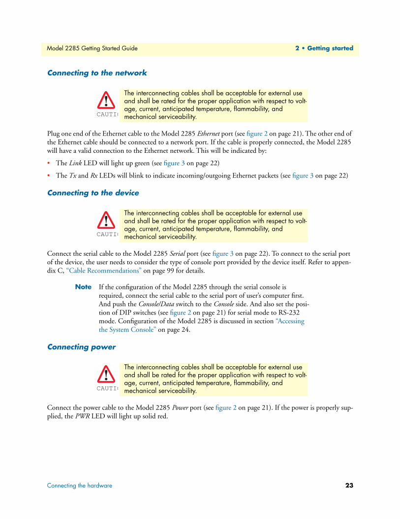
Connecting to the network
Plug one end of the Ethernet cable to the Model 2285 Ethernet port (see figure 2 on page 21). The other end of
the Ethernet cable should be connected to a network port. If the cable is properly connected, the Model 2285
will have a valid connection to the Ethernet network. This will be indicated by:
• The Link LED will light up green (see figure 3 on page 22)
• The Tx and Rx LEDs will blink to indicate incoming/outgoing Ethernet packets (see figure 3 on page 22)
Connecting to the device
Connect the serial cable to the Model 2285 Serial port (see figure 3 on page 22). To connect to the serial port
of the device, the user needs to consider the type of console port provided by the device itself. Refer to appen-
dix C, “Cable Recommendations” on page 99 for details.
Note If the configuration of the Model 2285 through the serial console is
required, connect the serial cable to the serial port of user’s computer first.
And push the Console/Data switch to the Console side. And also set the posi-
tion of DIP switches (see figure 2 on page 21) for serial mode to RS-232
mode. Configuration of the Model 2285 is discussed in section “Accessing
the System Console” on page 24.
Connecting power
Connect the power cable to the Model 2285 Power port (see figure 2 on page 21). If the power is properly sup-
plied, the PWR LED will light up solid red.
The interconnecting cables shall be acceptable for external use and shall be rated for the proper application with respect to volt-age, current, anticipated temperature, flammability, and mechanical serviceability.
The interconnecting cables shall be acceptable for external use and shall be rated for the proper application with respect to volt-age, current, anticipated temperature, flammability, and mechanical serviceability.
The interconnecting cables shall be acceptable for external use and shall be rated for the proper application with respect to volt-age, current, anticipated temperature, flammability, and mechanical serviceability.
CAUTIO
CAUTIO
CAUTIO
Connecting the hardware 23
Model 2285 Getting Started Guide 2 • Getting started
Accessing the System ConsoleThere are several ways to access the Model 2285. These methods are dependent on whether the user is located
at a local site or a remote site, or whether the user requires a menu-driven interface, graphic menu system or
CLI (Command Line Interface).
• System console: Local users can connect directly to the system console port of the Model 2285 using the
serial console cable.
• Remote console: Remote users who require a menu-driven interface can utilize Telnet (port 23) or SSH
(port 22) connections to the Model 2285 using Telnet or SSH client.
Note The Model 2285 supports only the SSH v2, so user must use the SSH client
which is able to support SSH v2.
• Web: Remote users who want to use a web browser to configure the Model 2285 can connect to the
Model 2285 using a conventional web browser, such as Internet Explorer or Netscape Navigator.
The above methods require user authentication by the Model 2285 system.
Using the System console1. Connect one end of the console cable to the console port on the Model 2285 (see figure 3 on page 22).
2. Push the Console/Data switch to the Console side.
3. Set the position of DIP switch for serial mode to RS-232 mode. Configuration of DIP switch is discussed
in appendix C, “Cable Recommendations” on page 99.
4. Connect the other end of the cable to the serial port of the user’s computer.
5. Run a terminal emulator program (i.e. HyperTerminal). Set the serial configuration parameters of the ter-
minal emulation program as follows:
– 9600 Baud rate
– Data bits 8
– Parity None
– Stop bits 1
– No flow control
6. Press the [ENTER] key.
7. Enter your username and password to log into the Model 2285. The factory default user settings are
as follows.
– Login: superuser
– Password: superuser
The interconnecting cables shall be acceptable for external use and shall be rated for the proper application with respect to volt-age, current, anticipated temperature, flammability, and mechanical serviceability.CAUTIO
Accessing the System Console 24
Model 2285 Getting Started Guide 2 • Getting started
2285 login: root
Password:
#
8. After login, user can use various shell commands in the CLI (command line interface). For details on the
CLI, refer to the chapter 7, “CLI guide” on page 87.
9. “editconf” command will allow you to enter the text-menu driven interface and the menu
Using a Static IP Address ................................................................................................................................30
IP address ..................................................................................................................................................31
Primary and Secondary DNS ....................................................................................................................31
Using DHCP ..................................................................................................................................................31
MIB-II System objects Configuration .............................................................................................................33
Access Control Configuration .........................................................................................................................34
Management using SNMP ..............................................................................................................................35
Dynamic DNS Configuration ...............................................................................................................................35
IP Filtering ............................................................................................................................................................38
Option and IP address/mask ...........................................................................................................................39
Service ............................................................................................................................................................39
SYSLOG server configuration................................................................................................................................40
Locating server configuration ..........................................................................................................................41
Locating server communication protocol ........................................................................................................41
NFS server configuration.......................................................................................................................................42
TCP service configuration .....................................................................................................................................42
29
Model 2285 Getting Started Guide 3 • Network configuration
IP configurationThe Model 2285 requires a valid IP address to operate within the user’s network environment. If the IP
address is not readily available, contact the system administrator to obtain a valid IP address for the Model
2285.
Note The Model 2285 requires a unique IP address to connect to the user’s net-
work.
The users may choose one of three Internet protocols in setting up the Model 2285 IP address: i.e.,
• Static IP
• DHCP (Dynamic Host Configuration Protocol)
The Model 2285 is initially defaulted to STATIC mode, with a static IP address of 192.168.161.5. Table 3
shows the configuration parameters for all three IP configurations. Figure 7 shows the actual web-based GUI to
change the user’s IP configuration.
Figure 7. IP configuration
Using a Static IP AddressWhen using a Static IP address, the user must manually specify all the configuration parameters associated with
the IP address of the Model 2285. These include the IP address, the network subnet mask, the gateway com-
puter and the domain name server computers. This section will look at each of these in more detail.
Note The Model 2285 will attempt to locate all this information every time it is
turned on.
Table 3. IP configuration parameters
Mode Parameters
Static IP IP addressSubnet mask
Default gatewayPrimary DNS/ Secondary DNS
DHCP Primary DNS/ Secondary DNS (Optional)
IP configuration 30
Model 2285 Getting Started Guide 3 • Network configuration
IP addressA Static IP address acts as a “static” or permanent identification number. This number is assigned to a com-
puter to act as its location address on the network. Computers use these IP addresses to identify and talk to
each other on a network. Therefore, it is imperative that the selected IP address be both unique and valid in a
network environment.
Note 192.168.1.x will never be assigned by an ISP (Internet Service Provider). IP
addresses using this form are considered private. Actual applications of the
Model 2285 may require access to public network, such as the Internet. If so,
a valid public IP address must be assigned to the user’s computer. A public IP
address is usually purchased or leased from a local ISP.
Subnet maskA subnet represents all the network hosts in one logical location, such as a building or local area network
(LAN). The Model 2285 will use the subnet mask setting to verify the origin of all packets. If the desired
TCP/IP host specified in the packet is in the same geographic location (on the local network segment) as
defined by the subnet mask, the Model 2285 will establish a direct connection. If the desired TCP/IP host
specified in the packet is not identified as belonging on the local network segment, a connection is established
through the given default gateway.
Default gatewayA gateway is a network point that acts as a portal to another network. This point is usually the computer or
computers that control traffic within a network or a local ISP (Internet service provider). The Model 2285 uses
the IP address of the default gateway computer to communicate with hosts outside the local network environ-
ment. Refer to the network administrator for a valid gateway IP address.
Primary and Secondary DNSThe DNS (Domain Name System) server is used to locate and translate the correct IP address for a requested
web site address. A domain name is the web address (i.e. www.yahoo.com) and is usually easier to remember.
The DNS server is the host that can translate such text-based domain names into the numeric IP addresses for
a TCP/IP connection.
The IP address of the DNS server must be able to access the host site with the provided domain name. The
Model 2285 provides the ability to configure the required IP addresses of both the Primary and Secondary
DNS servers addresses. (The secondary DNS server is specified for use when the primary DNS server is
unavailable.)
Using DHCPDynamic host configuration protocol (DHCP) is a communications protocol that lets network administrators
manage and automate the assignment of IP addresses centrally in an organization’s network. DHCP allows the
network administrator the ability to provise and distribute IP addresses from a central point and automatically
send a new IP address when a computer is plugged into a different network location.
When in static IP mode, the IP address must be entered manually at each computer. If a computer is moved to
another network location, a new IP address may need to be assigned. DHCP allows all the parameters, includ-
ing the IP address, subnet mask, gateway and DNS servers to be automatically configured when the IP address
is assigned. DHCP uses a “lease” concept in assigning IP addresses to a computer. It limits the amount of time
a given IP address will be valid for a computer. All the parameters required to assign an IP address are automat-
IP configuration 31
Model 2285 Getting Started Guide 3 • Network configuration
ically configured on the DHCP server side, and each DHCP client computer receives this information when
the IP address is provided at its boot-up.
Each time the device is reset, the Model 2285 broadcasts a DHCP request over the network. The reply gener-
ated by the DHCP server contains the IP address, as well as the subnet mask, gateway address, DNS servers
and the “lease” time. The Model 2285 immediately places this information in its memory. Once the “lease”
expires, the Model 2285 will request a renewal of the “lease” time from the DHCP server. If the DHCP server
approves the request for renewal, the Model 2285 can continue to work with the current IP address. If the
DHCP server denies the request for renewal, the Model 2285 will start the procedure to request a new IP
address from the DHCP server.
Note While in DHCP mode, all network-related parameters for the Model 2285
are to be configured automatically, including the DNS servers. If the DNS
server is not automatically configured, the user may manually configure the
settings by entering the primary and secondary DNS IP addresses. To force
an automatic configuration of the DNS address, set the primary and second-
ary DNS IP addresses to 0.0.0.0 (recommended).
A DHCP sever assigns IP addresses dynamically from an IP address pool, which is managed by the network
administrator. This means that the DHCP client, i.e. the Model 2285, receives a different IP address each time
it boots up. The IP address should be reserved on the DHCP server side to assure that the user always knows
the newly assigned Model 2285 address. In order to reserve the IP address in the DHCP network, the adminis-
trator needs the MAC address of the Model 2285 found on the label sticker at the bottom of the Model 2285.
IP configuration 32
Model 2285 Getting Started Guide 3 • Network configuration
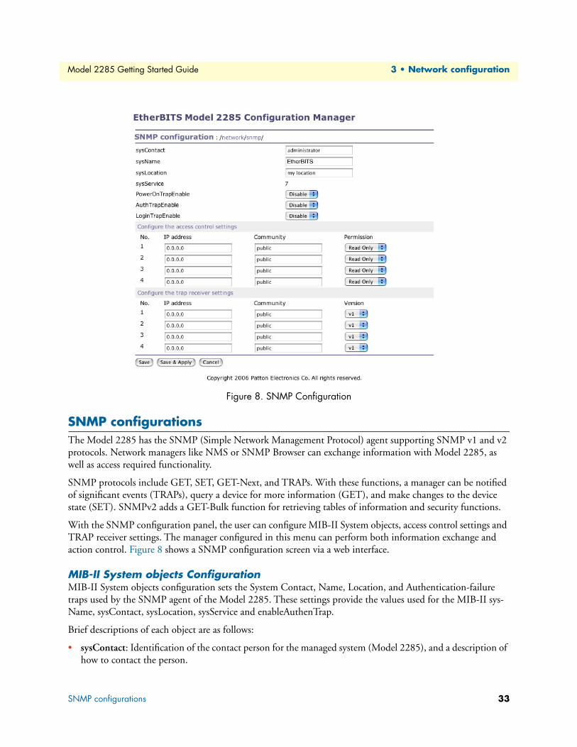
Figure 8. SNMP Configuration
SNMP configurationsThe Model 2285 has the SNMP (Simple Network Management Protocol) agent supporting SNMP v1 and v2
protocols. Network managers like NMS or SNMP Browser can exchange information with Model 2285, as
well as access required functionality.
SNMP protocols include GET, SET, GET-Next, and TRAPs. With these functions, a manager can be notified
of significant events (TRAPs), query a device for more information (GET), and make changes to the device
state (SET). SNMPv2 adds a GET-Bulk function for retrieving tables of information and security functions.
With the SNMP configuration panel, the user can configure MIB-II System objects, access control settings and
TRAP receiver settings. The manager configured in this menu can perform both information exchange and
action control. Figure 8 shows a SNMP configuration screen via a web interface.
MIB-II System objects ConfigurationMIB-II System objects configuration sets the System Contact, Name, Location, and Authentication-failure
traps used by the SNMP agent of the Model 2285. These settings provide the values used for the MIB-II sys-
Name, sysContact, sysLocation, sysService and enableAuthenTrap.
Brief descriptions of each object are as follows:
• sysContact: Identification of the contact person for the managed system (Model 2285), and a description of
how to contact the person.
SNMP configurations 33
Model 2285 Getting Started Guide 3 • Network configuration
• sysName: Name used to identify the system. By convention, this is the fully qualified domain name of
the node.
• sysLocation: The physical location of the system (e.g., Room 384, Operations Lab, etc.).
• sysService (read only): A series of values, separated by commas, that indicate the set of services that the sys-
tem provides. By default, Model 2285 only supports an Application(7) service level.
• EnablePoweronTraps: Indicates whether the SNMP agent process is permitted to generate power-on traps.
• EnableAuthenTrap: Indicates whether the SNMP agent process is permitted to generate authentication-
failure traps. The value of this object overrides any configuration information; as such, it provides a means
whereby all authentication-failure traps may be disabled..
• EnableLoginTrap: Indicates whether the SNMP agent process is permitted to generate system login traps
for console, telnet and Web access.
If users need support for adding or modifying MIBs, please contact Patton technical support.
Note For more information about the MIBs and SNMP, see the RFCs 1066,
1067, 1098, 1317, 1318 and 1213.
Access Control ConfigurationAccess Control defines accessibility of managers to the Model 2285 SNMP agent. Only the manager set in this
menu can access Model 2285 SNMP agent to exchange information and control actions. If there is no speci-
fied IP address (all IP address are defaulted to 0.0.0.0), a manager from any host can access the Model 2285
SNMP agent.
Trap Receiver ConfigurationThe Trap receiver defines managers, which can be notified of significant events (TRAP) from the Model 2285
SNMP agent.
SNMP configurations 34
Model 2285 Getting Started Guide 3 • Network configuration
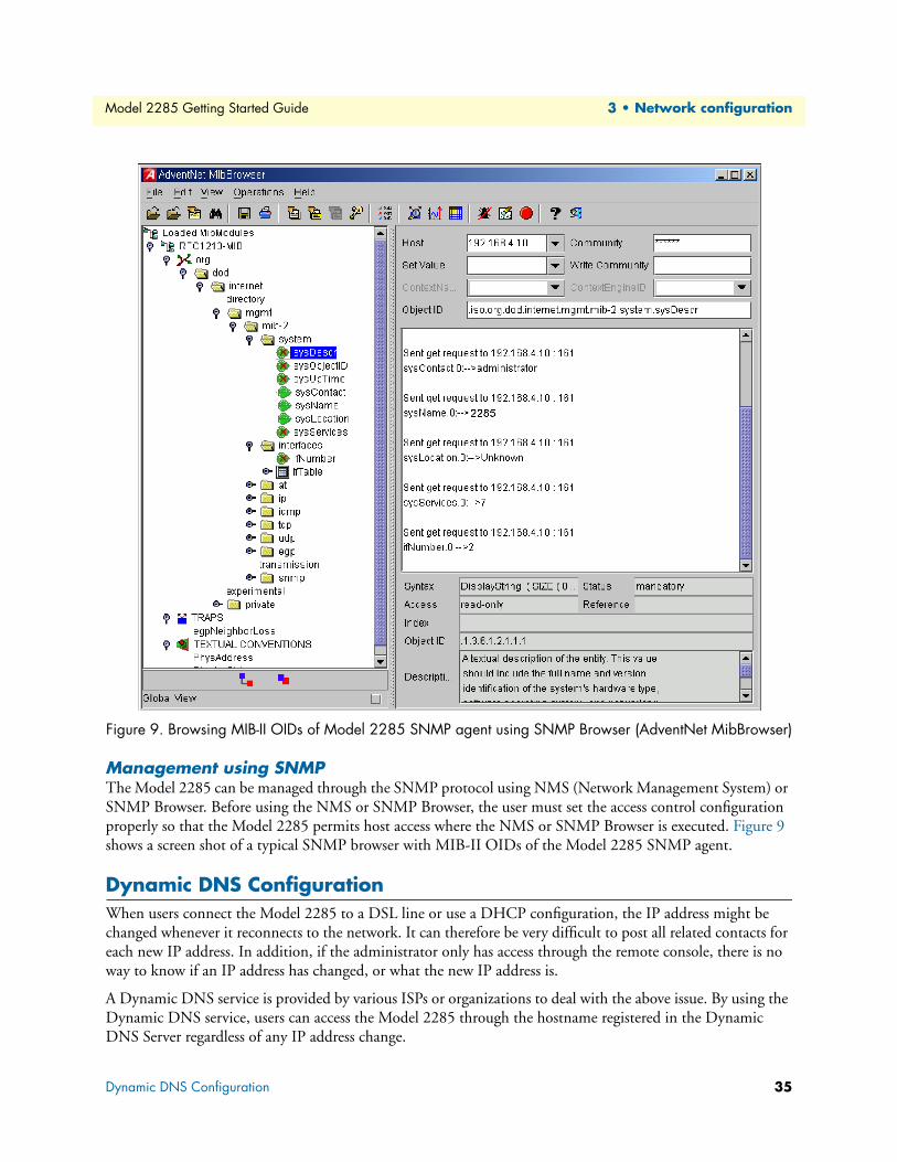
Figure 9. Browsing MIB-II OIDs of Model 2285 SNMP agent using SNMP Browser (AdventNet MibBrowser)
Management using SNMPThe Model 2285 can be managed through the SNMP protocol using NMS (Network Management System) or
SNMP Browser. Before using the NMS or SNMP Browser, the user must set the access control configuration
properly so that the Model 2285 permits host access where the NMS or SNMP Browser is executed. Figure 9
shows a screen shot of a typical SNMP browser with MIB-II OIDs of the Model 2285 SNMP agent.
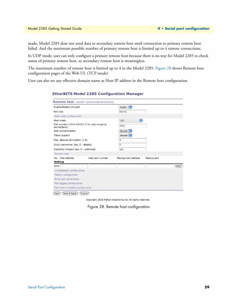
Dynamic DNS ConfigurationWhen users connect the Model 2285 to a DSL line or use a DHCP configuration, the IP address might be
changed whenever it reconnects to the network. It can therefore be very difficult to post all related contacts for
each new IP address. In addition, if the administrator only has access through the remote console, there is no
way to know if an IP address has changed, or what the new IP address is.
A Dynamic DNS service is provided by various ISPs or organizations to deal with the above issue. By using the
Dynamic DNS service, users can access the Model 2285 through the hostname registered in the Dynamic
DNS Server regardless of any IP address change.
Dynamic DNS Configuration 35
Model 2285 Getting Started Guide 3 • Network configuration
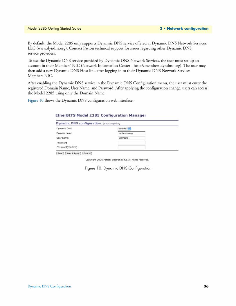
By default, the Model 2285 only supports Dynamic DNS service offered at Dynamic DNS Network Services,
LLC (www.dyndns.org). Contact Patton technical support for issues regarding other Dynamic DNS
service providers.
To use the Dynamic DNS service provided by Dynamic DNS Network Services, the user must set up an
account in their Members’ NIC (Network Information Center - http://members.dyndns. org). The user may
then add a new Dynamic DNS Host link after logging in to their Dynamic DNS Network Services
Members NIC.
After enabling the Dynamic DNS service in the Dynamic DNS Configuration menu, the user must enter the
registered Domain Name, User Name, and Password. After applying the configuration change, users can access
the Model 2285 using only the Domain Name.
Figure 10 shows the Dynamic DNS configuration web interface.
Figure 10. Dynamic DNS Configuration
Dynamic DNS Configuration 36
Model 2285 Getting Started Guide 3 • Network configuration
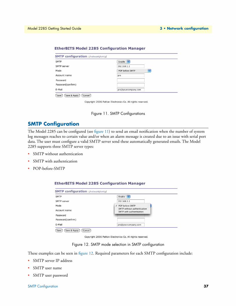
Figure 11. SMTP Configurations
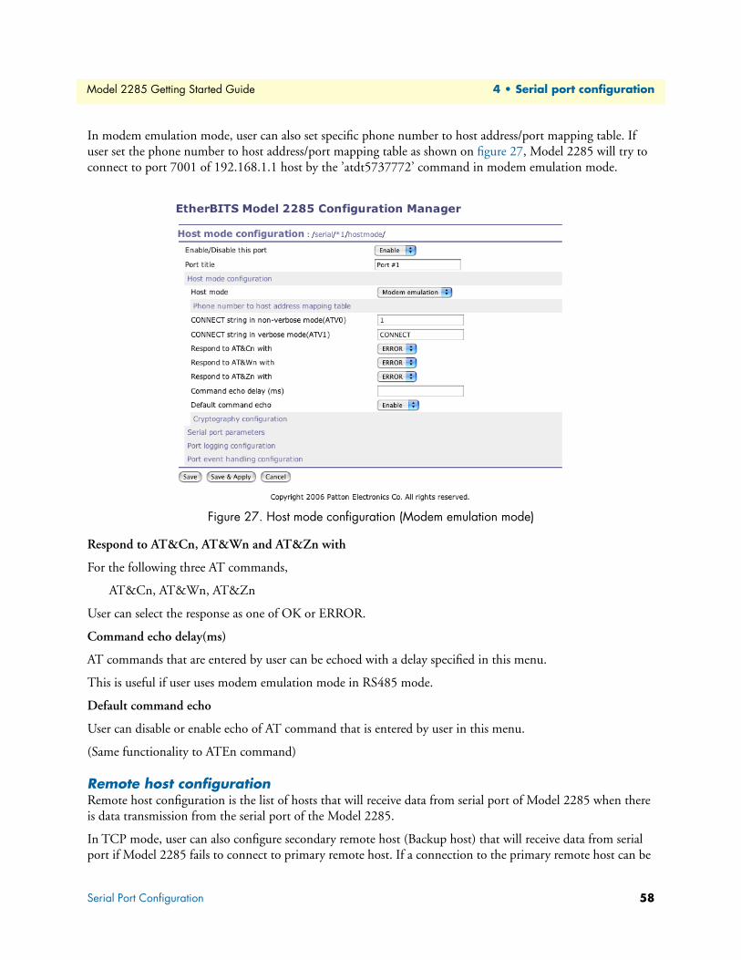
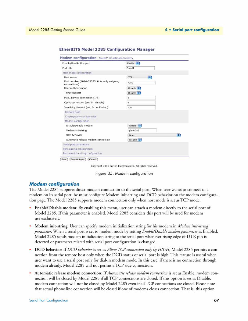
SMTP ConfigurationThe Model 2285 can be configured (see figure 11) to send an email notification when the number of system
log messages reaches to certain value and/or when an alarm message is created due to an issue with serial port
data. The user must configure a valid SMTP server send these automatically generated emails. The Model
2285 supports three SMTP server types:
• SMTP without authentication
• SMTP with authentication
• POP-before-SMTP
Figure 12. SMTP mode selection in SMTP configuration
These examples can be seen in figure 12. Required parameters for each SMTP configuration include:
• SMTP server IP address
• SMTP user name
• SMTP user password
SMTP Configuration 37
Model 2285 Getting Started Guide 3 • Network configuration
• Device mail address
The device mail address specifies the sender’s email address for all log and alarm delivery emails. SMTP servers
often check only the sender’s host domain name of the email address for validity. Consequently, the email
address set for the device can use an arbitrary username with a registered hostname (i.e.
Serial Port Configuration.......................................................................................................................................47
Port Enable/Disable ........................................................................................................................................48
Port Title ........................................................................................................................................................48
Serial port parameters ......................................................................................................................................63
Port Logging ...................................................................................................................................................68
Port event handling configurations .................................................................................................................69
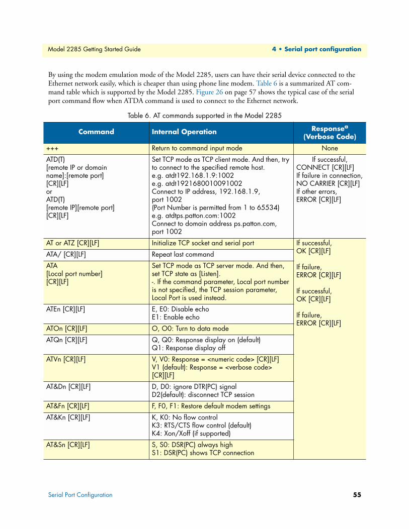
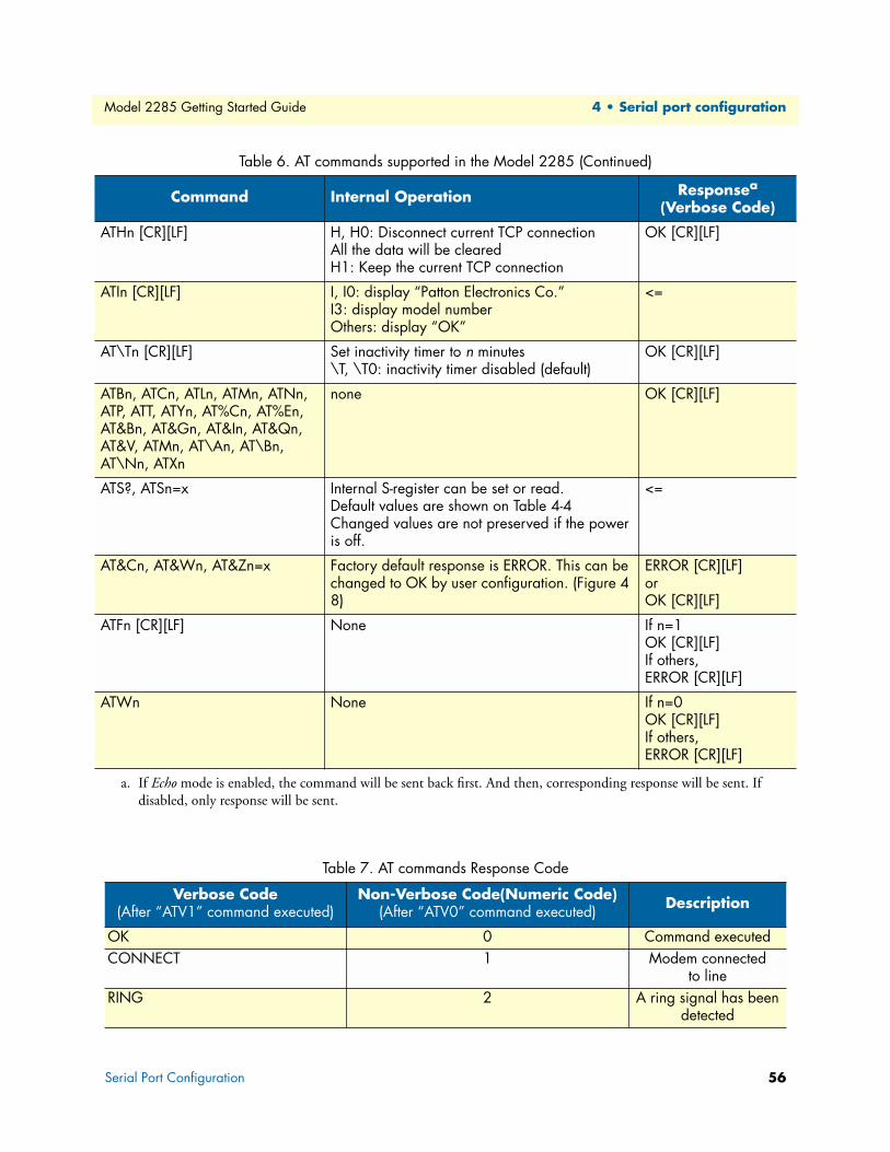
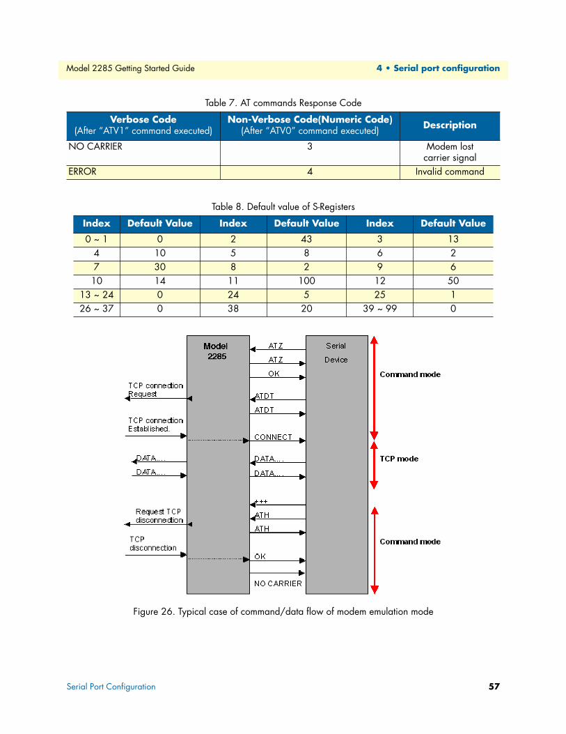
ATD(T)[remote IP or domain name]:[remote port][CR][LF]orATD(T)[remote IP][remote port][CR][LF]
Set TCP mode as TCP client mode. And then, try to connect to the specified remote host.e.g. atdt192.168.1.9:1002e.g. atdt1921680010091002Connect to IP address, 192.168.1.9, port 1002(Port Number is permitted from 1 to 65534)e.g. atdtps.patton.com:1002Connect to domain address ps.patton.com, port 1002
If successful,CONNECT [CR][LF]If failure in connection,NO CARRIER [CR][LF]If other errors,ERROR [CR][LF]
AT or ATZ [CR][LF] Initialize TCP socket and serial port If successful, OK [CR][LF]
If failure,ERROR [CR][LF]
If successful, OK [CR][LF]
If failure,ERROR [CR][LF]
ATA/ [CR][LF] Repeat last command
ATA[Local port number][CR][LF]
Set TCP mode as TCP server mode. And then, set TCP state as [Listen].-. If the command parameter, Local port number is not specified, the TCP session parameter, Local Port is used instead.
ATEn [CR][LF] E, E0: Disable echoE1: Enable echo
ATOn [CR][LF] O, O0: Turn to data mode
ATQn [CR][LF] Q, Q0: Response display on (default)Q1: Response display off
System Logging .....................................................................................................................................................72
Device Name Configuration..................................................................................................................................74
Date and Time Settings .........................................................................................................................................74
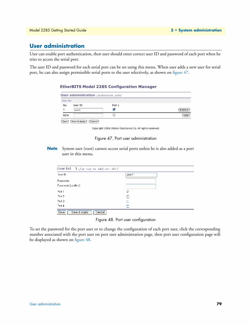
User administration ...............................................................................................................................................79
71
Model 2285 Getting Started Guide 5 • System administration
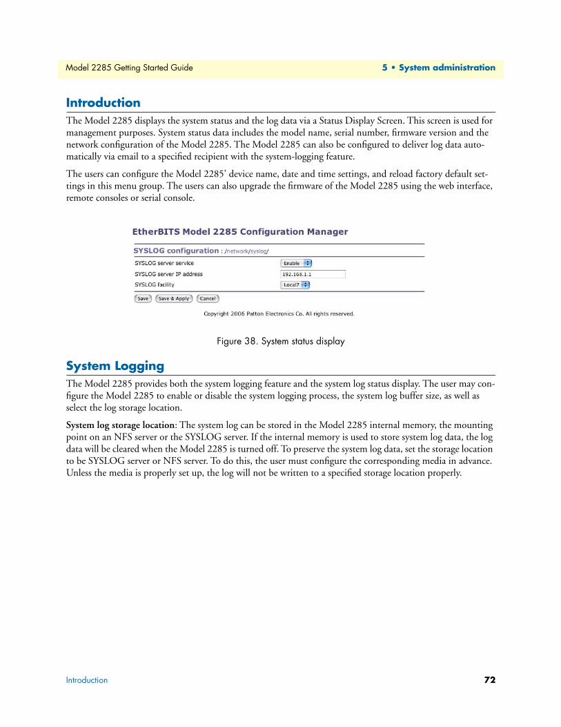
IntroductionThe Model 2285 displays the system status and the log data via a Status Display Screen. This screen is used for
management purposes. System status data includes the model name, serial number, firmware version and the
network configuration of the Model 2285. The Model 2285 can also be configured to deliver log data auto-
matically via email to a specified recipient with the system-logging feature.
The users can configure the Model 2285’ device name, date and time settings, and reload factory default set-
tings in this menu group. The users can also upgrade the firmware of the Model 2285 using the web interface,
remote consoles or serial console.
Figure 38. System status display
System LoggingThe Model 2285 provides both the system logging feature and the system log status display. The user may con-
figure the Model 2285 to enable or disable the system logging process, the system log buffer size, as well as
select the log storage location.
System log storage location: The system log can be stored in the Model 2285 internal memory, the mounting
point on an NFS server or the SYSLOG server. If the internal memory is used to store system log data, the log
data will be cleared when the Model 2285 is turned off. To preserve the system log data, set the storage location
to be SYSLOG server or NFS server. To do this, the user must configure the corresponding media in advance.
Unless the media is properly set up, the log will not be written to a specified storage location properly.
Introduction 72
Model 2285 Getting Started Guide 5 • System administration
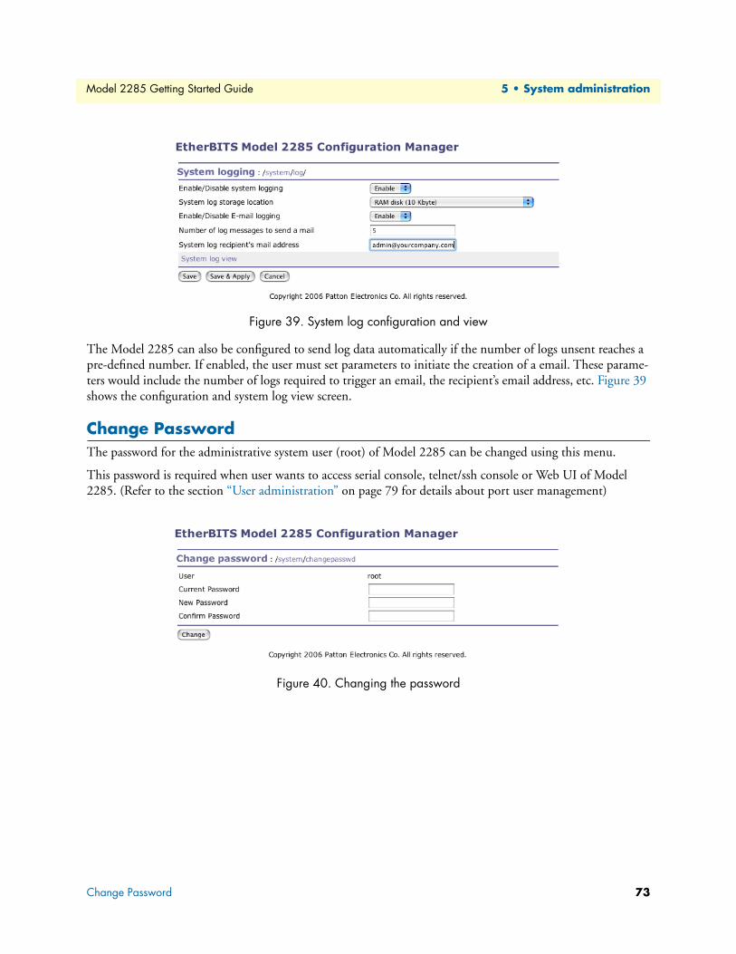
Figure 39. System log configuration and view
The Model 2285 can also be configured to send log data automatically if the number of logs unsent reaches a
pre-defined number. If enabled, the user must set parameters to initiate the creation of a email. These parame-
ters would include the number of logs required to trigger an email, the recipient’s email address, etc. Figure 39
shows the configuration and system log view screen.
Change PasswordThe password for the administrative system user (root) of Model 2285 can be changed using this menu.
This password is required when user wants to access serial console, telnet/ssh console or Web UI of Model
2285. (Refer to the section “User administration” on page 79 for details about port user management)
Figure 40. Changing the password
Change Password 73
Model 2285 Getting Started Guide 5 • System administration
Device Name ConfigurationThe Model 2285 has its own name for administrative purposes. Figure 41 shows the device name configura-
tion screen. When user changes Device name, hostname of Model 2285 will be also changed.
Figure 41. Device name configuration
Note The user cannot set space character as a device name. If user sets blank as
Device name then hostname is set as IP address of Model
2285 automatically.
And also the device name is utilized for management program, Model 2285
Manager.
Date and Time SettingsThe Model 2285 maintains current date and time information.
Note The Model 2285 does not have a battery for internal clock. Current date and
time setting will not be retained after system rebooting. So it is recom-
mended to use NTP server to maintain correct date and time in the
Model 2285.
The user can change the current date and time, as shown in figure 42.
Figure 42. Date and time configuration
Device Name Configuration 74
Model 2285 Getting Started Guide 5 • System administration
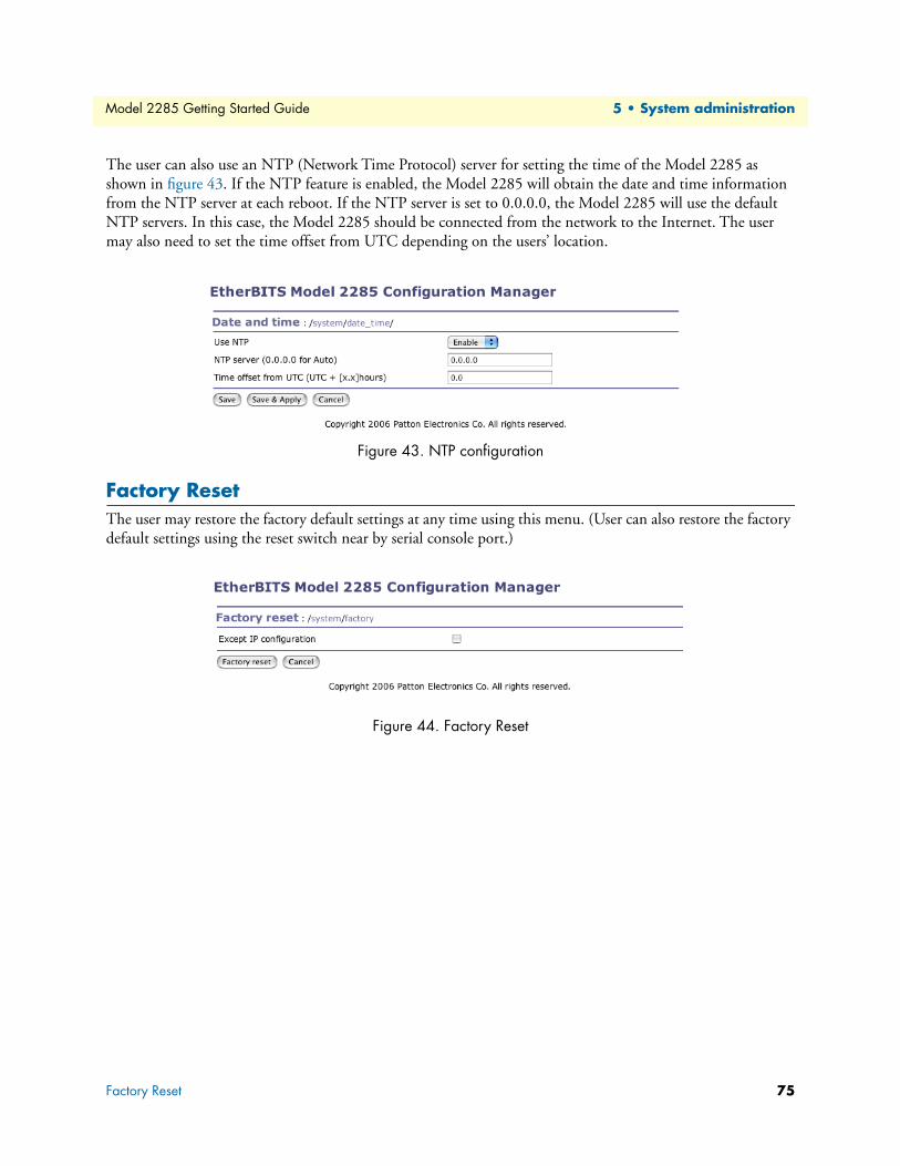
The user can also use an NTP (Network Time Protocol) server for setting the time of the Model 2285 as
shown in figure 43. If the NTP feature is enabled, the Model 2285 will obtain the date and time information
from the NTP server at each reboot. If the NTP server is set to 0.0.0.0, the Model 2285 will use the default
NTP servers. In this case, the Model 2285 should be connected from the network to the Internet. The user
may also need to set the time offset from UTC depending on the users’ location.
Figure 43. NTP configuration
Factory ResetThe user may restore the factory default settings at any time using this menu. (User can also restore the factory
default settings using the reset switch near by serial console port.)
Figure 44. Factory Reset
Factory Reset 75
Model 2285 Getting Started Guide 5 • System administration
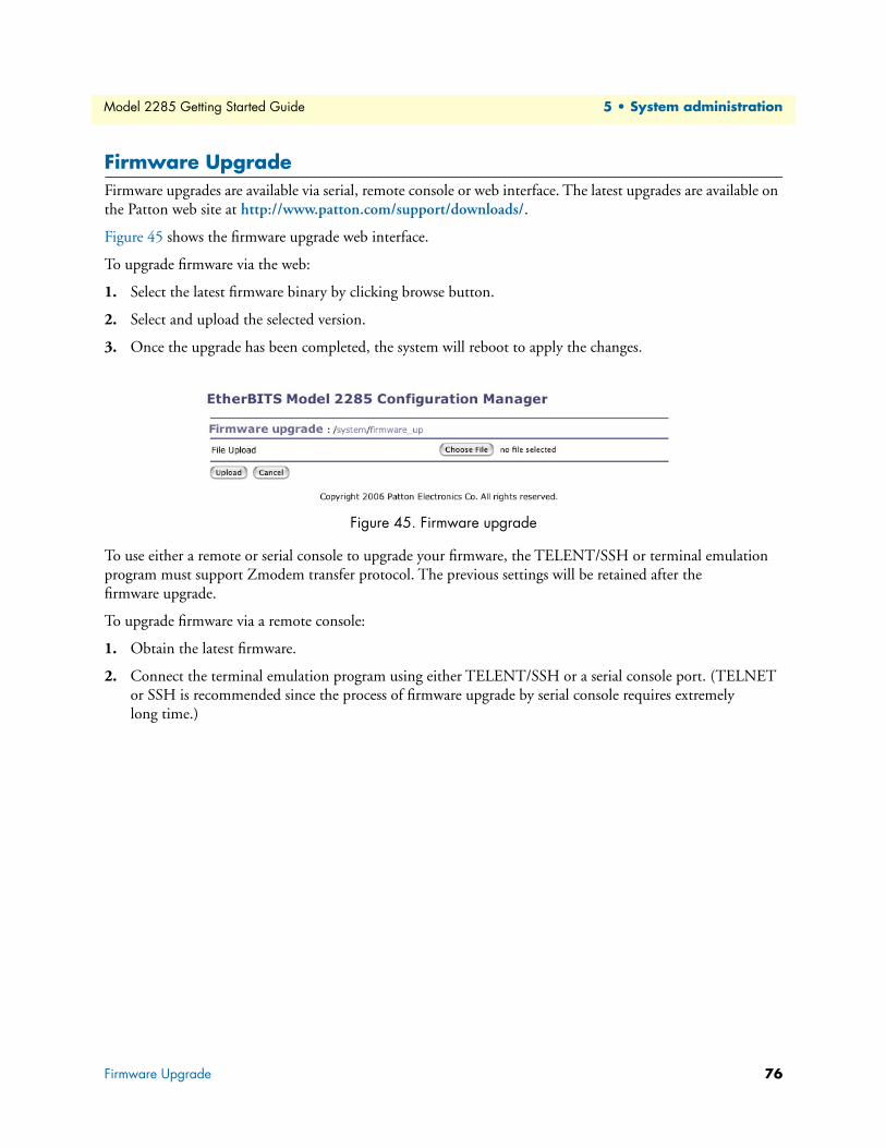
Firmware UpgradeFirmware upgrades are available via serial, remote console or web interface. The latest upgrades are available on
the Patton web site at http://www.patton.com/support/downloads/.
Figure 45 shows the firmware upgrade web interface.
To upgrade firmware via the web:
1. Select the latest firmware binary by clicking browse button.
2. Select and upload the selected version.
3. Once the upgrade has been completed, the system will reboot to apply the changes.
Figure 45. Firmware upgrade
To use either a remote or serial console to upgrade your firmware, the TELENT/SSH or terminal emulation
program must support Zmodem transfer protocol. The previous settings will be retained after the
firmware upgrade.
To upgrade firmware via a remote console:
1. Obtain the latest firmware.
2. Connect the terminal emulation program using either TELENT/SSH or a serial console port. (TELNET
or SSH is recommended since the process of firmware upgrade by serial console requires extremely
long time.)
Firmware Upgrade 76
Model 2285 Getting Started Guide 5 • System administration
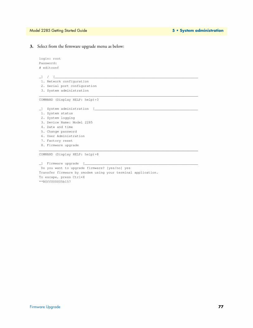
3. Select from the firmware upgrade menu as below:
Serial Ports Statistics ..............................................................................................................................................81
IP Statistics .....................................................................................................................................................82
Supported Linux Utilities ......................................................................................................................................88
File and disk utils ............................................................................................................................................88
System utilities ................................................................................................................................................88
Out-of-warranty service .............................................................................................................................92
Returns for credit ......................................................................................................................................92
Return for credit policy .............................................................................................................................92
Model 2285 Getting Started Guide 8 • Contacting Patton for assistance
IntroductionThis chapter contains the following information:
• “Contact information”—describes how to contact PATTON technical support for assistance.
• “Warranty Service and Returned Merchandise Authorizations (RMAs)”—contains information about the
RAS warranty and obtaining a return merchandise authorization (RMA).
Contact informationPatton Electronics offers a wide array of free technical services. If you have questions about any of our other
products we recommend you begin your search for answers by using our technical knowledge base. Here, we
have gathered together many of the more commonly asked questions and compiled them into a searchable
database to help you quickly solve your problems.
Patton support headquarters in the USA• Online support—available at http://www.patton.com
• E-mail support—e-mail sent to [email protected] will be answered within 1 business day
• Telephone support—standard telephone support is available 5 days a week, from 8:00am to 5:00pm EST
(1300 to 2200 UTC/GMT)—by calling +1 (301) 975-1007
• Fax—+1 (253) 663-5693
Alternate Patton support for Europe, Middle East, and Africa (EMEA)• Online support—available at http://www.patton-inalp.com
• E-mail support—email sent to [email protected] will be answered within 1 day
• Telephone support—standard telephone support is available five days a week—from 8:00 am to 5:00 pm
CET (0900 to 1800 UTC/GMT)—by calling +41 (0)31 985 25 55
• Fax—+41 (0)31 985 25 26
Warranty Service and Returned Merchandise Authorizations (RMAs)Patton Electronics is an ISO-9001 certified manufacturer and our products are carefully tested before ship-
ment. All of our products are backed by a comprehensive warranty program.
Note If you purchased your equipment from a Patton Electronics reseller, ask your
reseller how you should proceed with warranty service. It is often more con-
venient for you to work with your local reseller to obtain a replacement. Pat-
ton services our products no matter how you acquired them.
Warranty coverageOur products are under warranty to be free from defects, and we will, at our option, repair or replace the prod-
uct should it fail within one year from the first date of shipment. Our warranty is limited to defects in work-
manship or materials, and does not cover customer damage, lightning or power surge damage, abuse, or
Radio and TV Interference (FCC Part 15) ............................................................................................................94
CE Declaration of Conformity ..............................................................................................................................94
Authorized European Representative .....................................................................................................................94
93
Model 2285 Getting Started Guide A • Compliance information
EMC Compliance • FCC Part 15, Class A
• EN55022, Class A
• EN55024
Radio and TV Interference (FCC Part 15)This equipment generates and uses radio frequency energy, and if not installed and used properly-that is, in
strict accordance with the manufacturer's instructions-may cause interference to radio and television reception.
This equipment has been tested and found to comply with the limits for a Class A computing device in accor-
dance with the specifications in Subpart B of Part 15 of FCC rules, which are designed to provide reasonable
protection from such interference in a commercial installation. However, there is no guarantee that interfer-
ence will not occur in a particular installation. If the equipment causes interference to radio or television recep-
tion, which can be determined by disconnecting the cables, try to correct the interference by one or more of
the following measures: moving the computing equipment away from the receiver, re-orienting the receiving
antenna, and/or plugging the receiving equipment into a different AC outlet (such that the computing equip-
ment and receiver are on different branches).
CE Declaration of ConformityWe certify that the apparatus identified in this document conforms to the requirements of Council Directive
89/336/EEC, as amended by Directives 92/31/EEC, 93/68/EEC, and 2004/108/EC on the approximation of
the laws of the member states relating to electromagnetic compatibility.
The safety advice in the documentation accompanying this product shall be obeyed. The conformity to the
above directive is indicated by the CE sign on the device.
Power ....................................................................................................................................................................97
95
Model 2285 Getting Started Guide B • Specifications
Management• Web, Telnet, SSH, Serial console port or Model 2285 Manager
• O/S support: Windows 98/ME/NT/2000/XP
Serial interface 96
Model 2285 Getting Started Guide B • Specifications
• System log: Automatic email delivery of error log
• System statistics: Full-featured system status display
• Firmware: Stored in Flash memory and upgradeable via telnet or web
Security• Packet filtering firewall for controlled access to and from LAN/WAN. Support for 255 rules in 32 filter sets.
16 individual connection profiles.
• DoS Detection/protection. Intrusion detection, Logging of session, blocking and intrusion events and Real-
Time alerts. Logging or SMTP on event.
• Password protected system management with a username/password for console and virtual terminal. Sepa-
rate user selectable passwords for SNMP RO/RW strings.
• Access list determining up to 5 hosts/networks which are allowed to access management system SNMP/
HTTP/TELNET.
• Logging or SMTP on events: POST, POST errors, PPP/DHCP, IP.
Diagnostic LEDs• PWR (power) red LED
• Link (10/100 Base Link) green LED
• Rx (Serial receive for each port) amber LED
• Tx (Serial transmit for each port) amber LED
Environmental• Operating temperature: 0 to 50°C
• Storage temperature: -20 to 66°C
• Humidity: 90% (Non-condensing)
Physical• Dimensions: 1.02H x 3.22W x 4.48D in. (26H x 82W x 114D cm)
• Weight: 10.6 ounces (0.3 kg)
Power• TBD
Connect the equipment to a 36–60 VDC source that is electri-cally isolated from the AC source. The 36–60 VDC source is to be reliably connected to earth.
CAUTIO
Security 97
Model 2285 Getting Started Guide B • Specifications
Console and Serial port pin-outs..........................................................................................................................101
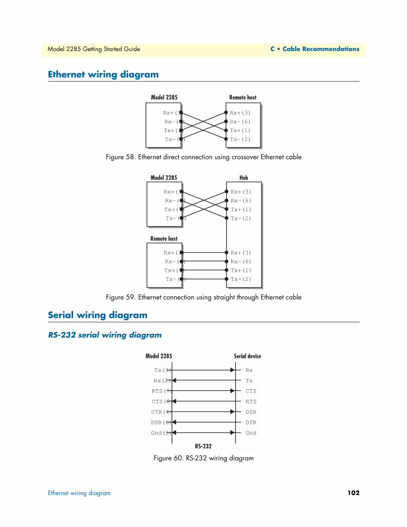
Serial wiring diagram...........................................................................................................................................102
RS-232 serial wiring diagram ........................................................................................................................102
RS-422/485 serial wiring diagram .................................................................................................................103
99
Model 2285 Getting Started Guide C • Cable Recommendations
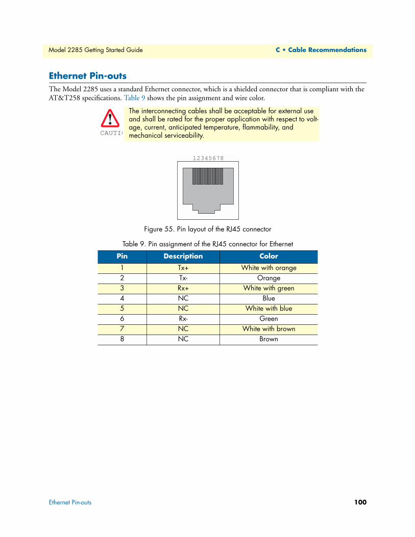
Ethernet Pin-outsThe Model 2285 uses a standard Ethernet connector, which is a shielded connector that is compliant with the
AT&T258 specifications. Table 9 shows the pin assignment and wire color.
Figure 55. Pin layout of the RJ45 connector
The interconnecting cables shall be acceptable for external use and shall be rated for the proper application with respect to volt-age, current, anticipated temperature, flammability, and mechanical serviceability.
Table 9. Pin assignment of the RJ45 connector for Ethernet
Pin Description Color
1 Tx+ White with orange2 Tx- Orange3 Rx+ White with green4 NC Blue5 NC White with blue6 Rx- Green7 NC White with brown8 NC Brown
CAUTIO
12345678
Ethernet Pin-outs 100
Model 2285 Getting Started Guide C • Cable Recommendations
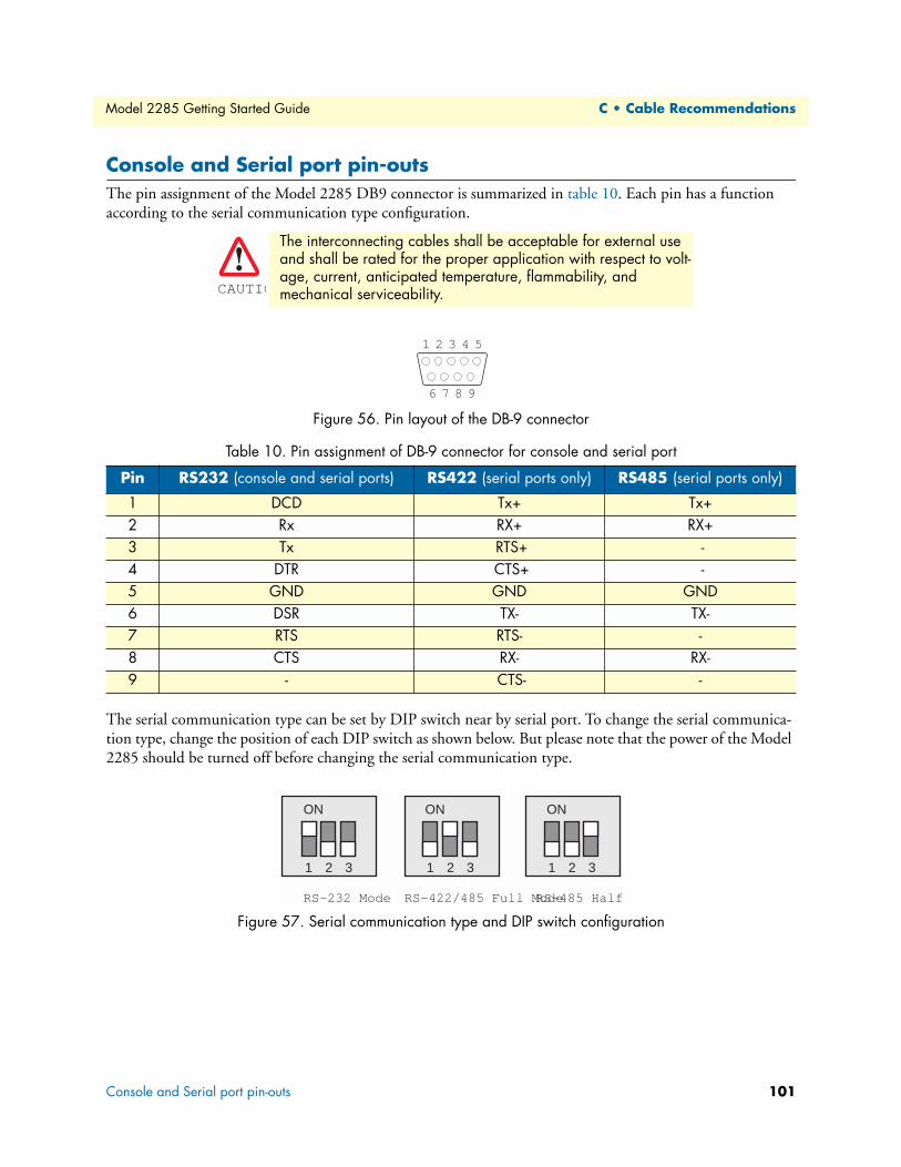
Console and Serial port pin-outsThe pin assignment of the Model 2285 DB9 connector is summarized in table 10. Each pin has a function
according to the serial communication type configuration.
Figure 56. Pin layout of the DB-9 connector
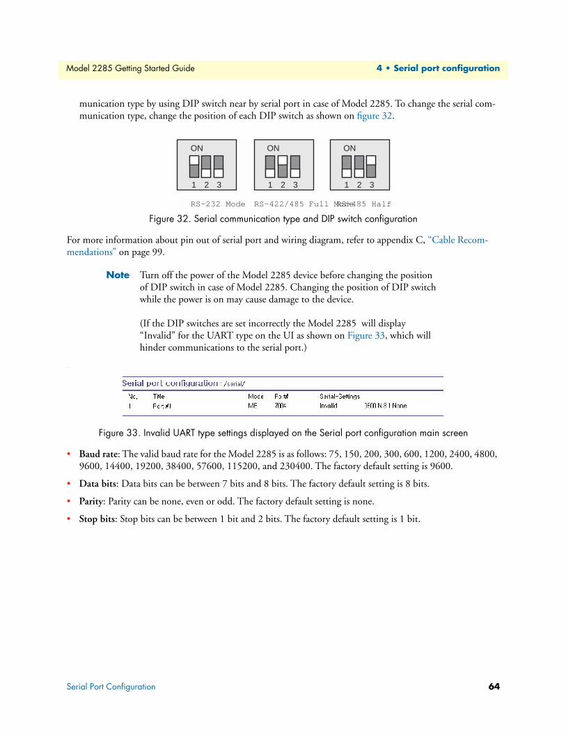
The serial communication type can be set by DIP switch near by serial port. To change the serial communica-
tion type, change the position of each DIP switch as shown below. But please note that the power of the Model
2285 should be turned off before changing the serial communication type.
Figure 57. Serial communication type and DIP switch configuration
The interconnecting cables shall be acceptable for external use and shall be rated for the proper application with respect to volt-age, current, anticipated temperature, flammability, and mechanical serviceability.
Table 10. Pin assignment of DB-9 connector for console and serial port
Pin RS232 (console and serial ports) RS422 (serial ports only) RS485 (serial ports only)
Main menu..........................................................................................................................................................110
RTC configuration menu ....................................................................................................................................110
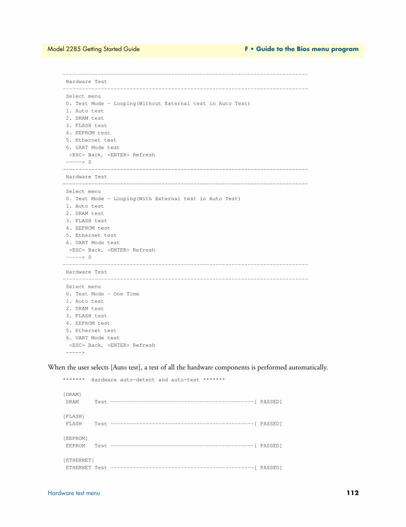
Hardware test menu ............................................................................................................................................111
A 4.5. Firmware upgrade menu ...........................................................................................................................114
109
Model 2285 Getting Started Guide F • Guide to the Bios menu program
OverviewThe bios menu provides a way to recover the Model 2285 unit, by using TFTP, as a disaster recovery option
and to diagnose the system hardware. If the user presses the <ESC> key within 3 seconds after the Model 2285
unit is powered up, the user will enter the bios menu program. From this menu program, the user can set vari-
ous system parameters, test system hardware, and perform firmware upgrades.
Note For Model 2285, the bios menu will be displayed only when the Console/
Data switch is located at the Console side.
Main menuAfter entering the bios menu program, the user will see following main menu page:
Main menu..........................................................................................................................................................110
RTC configuration menu ....................................................................................................................................110
Hardware test menu ............................................................................................................................................111
A 4.5. Firmware upgrade menu ...........................................................................................................................114
116
Model 2285 Getting Started Guide G • Using Model 2285 with Serial/IP
Model 2285 vs. Serial/IP options
Note The Model 2285 support only the SSLv3 encryption method, so user should
select one of “SSLv3 or TSLv1” option or “SSLv3 only” option in Serial/IP.
Table 12. Model 2285 vs. Serial/IP option compatibility matrix table
Serial Port Configuration of Model 2285 Serial/IP Configuration