Model 3500 Transmitter (MVD) or Model 3300 Peripheral Installation Instructions for Panel-Mount Quick Reference Guide P/N 20000885, Rev. B August 2005 For technical support, phone the support center nearest you: • In the U.S.A., phone 1-800-522-MASS (1-800-522-6277) • In Canada and Latin America, phone (303) 527-5200 • In Asia, phone (65) 6770-8155 • In the U.K., phone 0800 - 966 180 (toll-free) • Outside the U.K., phone +31 (0) 318 495 670
Transcript
Model 3500 Transmitter(MVD) orModel 3300 PeripheralInstallation Instructions forPanel-Mount
For technical support, phone the support center nearest you:• In the U.S.A., phone 1-800-522-MASS
(1-800-522-6277)• In Canada and Latin America, phone
(303) 527-5200• In Asia, phone (65) 6770-8155• In the U.K., phone 0800 - 966 180 (toll-free)• Outside the U.K., phone +31 (0) 318 495 670
1
BEFORE YOU BEGIN
This quick reference guide explains basic installation guidelines for mounting the Micro Motion® Model 3300/3500 MVD applications platform in a panel cutout.
For information on I.S. applications, refer to Micro Motion approval documentation.
For complete instructions about configuration, maintenance, and service, refer to the instruction manual shipped with the transmitter.
WARNING
Improper installation in a hazardous area can cause an explosion.
For information about hazardous applications, refer to Micro Motion approval documentation, shipped with the transmitter or available from the Micro Motion web site.
WARNING
Hazardous voltage can cause severe injury or death.
Install transmitter and complete all wiring before supplying power.
CAUTION
Improper installation could cause measurement error or meter failure.
Follow all instructions to ensure transmitter will operate correctly.
This Micro Motion product complies with all applicable European directives when properly installed in accordance with the instructions in this quick reference guide. Refer to the EC declaration of conformity for directives that apply to this product.
The EC declaration of conformity, with all applicable European directives, and the complete ATEX Installation Drawings and Instructions are available on the web at www.micromotion.com/atex or through your local Micro Motion support center.
Installation kitThe installation kit includes a bezel, frame, two mounting brackets with screws, a power supply wiring connector, and a retaining clip assembly for power supply wiring (see Figure 1).
The applications platform fits through a 5 7/16-inch (138 mm) square cutout in a panel that is 5/64 inch (2 mm) to 1/2 inch (13 mm) thick. The bezel provides a IP65 watertight seal between the panel cutout and the applications platform housing.
In addition, the installation kit includes:
• A bracketed wiring connector for screw-type connectors (see Figure 8), or
• I/O cables and connectors (see Figure 10)
Figure 1. Panel-mount installation kit
Power supplywiring connector
Retaining-clipassembly for
power supply wiring
2 x Mounting bracketwith screw
Frame Bezel
Panel thickness:• 5/64 inch (2 mm) minimum• 1/2 inch (13 mm) maximum
3
STEP 1. Choosing a location
Choose a location for the transmitter based on the requirements described below.
Environmental requirements
Install the transmitter where ambient temperature is between –4 and +140 °F (–20 and +60 °C).
DimensionsIf the Model 3300/3500 has screw-type wiring connectors, see Figure 2 for dimensions. If the Model 3300/3500 has I/O cables, see Figure 3 for dimensions. (See Figures 8 and 10 for illustrations of screw-type connectors versus I/O cables.)
Cable lengthsMaximum cable length from the sensor to the Model 3500 transmitter depends on the installation type and cable type:
• 4-wire remote transmitter: see Figure 4, then refer to Table 1 for maximum length of the 4-wire cable.
• Remote core processor with remote transmitter: see Figure 5, then refer to Table 1 for maximum length of the 4-wire cable and the 9-wire cable.
If you are installing the Model 3300 applications peripheral in combination with a transmitter, the maximum cable length from the transmitter’s frequency output to the Model 3300’s frequency input is 500 feet (150 meters).
6 1/2(165)
Bezel
Panel
6(152)
6 11/16(170)
Minimum 4 1/4" (108 mm) bend radius
Approvals tag
1/2(12)
8 3/4(222)
5 5/16(135)
Frame
6(152)
inches(mm)
5
Figure 4. 4-wire remote transmitter
Figure 5. Remote core processor with remote transmitter
Table 1. Maximum cable lengths
Cable type Wire gauge Maximum length
Micro Motion 9-wire Not applicable 60 feet (20 meters)
Micro Motion 4-wire Not applicable 1000 feet (300 meters)
• Signal wires (RS-485) 22 AWG (0,35 mm2) or larger 1000 feet (300 meters)
Cable from transmitter’s FO to Model 3300’s FI(1)
(1) Applies only to the Model 3300 applications peripheral when receiving frequency input from a remote Micro Motion transmitter such as an IFT9701 or RFT9739.
Not applicable 500 feet (150 meters)
Model 3500
4-wire cable
Sensor
Core processor(standard or enhanced)
Sensor
Junction box9-wire cable
4-wire cable
Model 3500
Core processor(standard only)
6
STEP 2. Installing the Model 3300/3500 in the panel
Refer to Figure 6 and follow these steps:
1. Insert the Model 3300/3500 through the cutout.
2. Slide the frame over the housing.
3. Insert the posts on the brackets into the rails on the housing.
4. Tighten the screws evenly to 10 to 14 inch-pounds (1,13 to 1,38 Nm) to ensure a watertight seal between the gasket and the panel.
Figure 6. Steps for installation in panel
STEP 3. Mounting the core processor
This step is required only for remote core processor with remote transmitter installations (see Figure 5). If you have a 4-wire remote installation, go to Step 4.
Figure 7 shows the remote core processor and mounting bracket. Using the mounting bracket, mount the core processor in a location compatible with the cable length requirements discussed in Step 1.
Step 2.1
Step 2.2
Step 2.3 Step 2.4
7
Figure 7. Remote core processor components
STEP 4. Connecting input and output wiring
If the Model 3300/3500 has screw-type connectors:
1. Plug the bracketed wiring connectors onto the terminal strips on the back panel of the Model 3300/3500 (see Figure 8). Tighten the captive screws to secure the bracket to the back panel.
Figure 8. Wiring connectors and terminals – screw-type connectors
Wiring connector for input/output wiring terminal strip
Wiring connector for sensor wiring terminal strip (Model 3500 only)
8
2. Connect input and output wiring to the appropriate terminals in the input/output wiring connector. Refer to the card that is inserted into the sleeve on the top panel (shown in Figure 9), and Table 2.
• Use 24 to 16 AWG (0,25 to 1,5 mm2) twisted-pair shielded wire.
1. Plug the bracketed wiring connector onto the terminal strips on the back panel of the Model 3300/3500 (see Figure 10). Tighten the captive screws to secure the bracket to the back panel.
Figure 10. Wiring connectors and terminals – I/O cables
2. Attach the supplied I/O terminal block to a DIN rail. The terminal block fits various rail types. See Figure 11.
3. Plug the connector for input/output wiring onto the I/O terminal block. Tighten the captive screws to secure the connector to the I/O terminal block.
4. Connect input and output wiring to the appropriate terminals on the I/O terminal block. Refer to the label attached to the terminal block (shown in Figure 12), and Table 3.
• Use 24 to 16 AWG (0,25 to 1,5 mm2) twisted-pair shielded wire.
• Ground the shields at a single point only.
The I/O terminal block ground is available for continuation of user cable shielding to I/O cable shielding. The cable connector does not connect the I/O cable shielding to the chassis ground.
If you are installing the Model 3300 applications peripheral, this step is not required. Go to Step 6.
To connect the Model 3500 transmitter to a Micro Motion sensor, follow the instructions below.
Installation options
Sensor wiring depends on the Model 3500 connector type (screw-type connectors or I/O cables) and on the installation configuration:
• 4-wire remote transmitter (requires a 4-wire cable; see Figure 4 and Wiring instructions for 4-wire remote installations)
• Remote core processor with remote transmitter (requires both a 4-wire and a 9-wire cable; see Figure 5 and Wiring instructions for remote core processor with remote transmitter installations)
Wiring instructions for 4-wire remote installations
1. Prepare the cable as described in the sensor documentation.
2. Connect the cable to the core processor as described in the sensor documentation.
a. Identify the wires in the 4-wire cable. The 4-wire cable supplied by Micro Motion consists of one pair of 18 AWG (0,75 mm2) wires (red and black), which should be used for the VDC connection, and one pair of 22 AWG (0,35 mm2) wire (green and white), which should be used for the RS-485 connection.
b. For transmitters with screw-type connectors, connect the four wires from the core processor to the appropriate terminals on the transmitter. See Table 4 and Figure 13 (standard core processor) or Figure 14 (enhanced core processor). No bare wires should remain exposed. Do not ground the shield, braid, or drain wire(s) at the transmitter.
Table 4. Transmitter terminals for 4-wire cable
Connector type
Screw-type I/O cable Wire color(1)
(1) Wire colors apply only to 4-wire cable supplied by Micro Motion.
Function
c 4 4 Red VDC+
a 4 10 Black VDC–
c 6 7 White RS-485A
a 6 3 Green RS-485B
13
Figure 13. 4-wire cable to Model 3500 – screw-type connectors and standard core processor
Figure 14. 4-wire cable to Model 3500 – screw-type connectors and enhanced core processor
Core processor terminals
4-wire cableMaximum cable length:
see Table 1
VDC+(Red)
VDC–(Black)
RS-485B(Green)
RS-485A(White)
User-supplied or factory-supplied cable
Model 3500 Sensor wiring terminals
(see Figure 8)
VDC+(Red)
RS-485A(White)
VDC–(Black)
RS-485B(Green)
aaaaaaaaaaaaaaaa
cccccccccccccccc
2468101214161820222426283032
Core processor terminals
4-wire cableMaximum cable length:
see Table 1
User-supplied or factory-supplied cable
Model 3500 Sensor wiring terminals
(see Figure 8)
VDC+(Red)
RS-485A(White)
VDC–(Black)
RS-485B(Green)
aaaaaaaaaaaaaaaa
cccccccccccccccc
2468101214161820222426283032VDC+ (Red)
RS-485B (Green)RS-485A (White)
VDC– (Black)
14
c. For transmitters with I/O cables:
- Attach the supplied terminal block to a DIN rail. The terminal block accommodates various rail types (see Figure 15).
- Plug the I/O cable connector onto the terminal block. Tighten the captive screws to secure the connector to the terminal block.
- Connect the four wires from the core processor to the appropriate terminals on the terminal block. See Table 4 and Figure 16 (standard core processor) or Figure 17 (enhanced core processor). No bare wires should remain exposed. Do not ground the shield, braid, or drain wire(s) at the transmitter.
Figure 15. Installing terminal block for sensor wiring on DIN rail
2 11/16(68)
TS 15 TS 32
TS 35 x 7,5 TS 35 x 15
9(229)
3 1/16(77)
2 1/4(57)
2 5/16(58)
2 1/2(63)
2 9/16(66)
inches(mm)
Terminal block for sensor wiring
Cable for sensor wiring (attached to Model 3500)
Connector
15
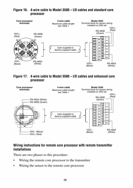
Figure 16. 4-wire cable to Model 3500 – I/O cables and standard core processor
Figure 17. 4-wire cable to Model 3500 – I/O cables and enhanced core processor
Wiring instructions for remote core processor with remote transmitter installations
There are two phases to this procedure:
• Wiring the remote core processor to the transmitter
• Wiring the sensor to the remote core processor
Core processor terminals
4-wire cableMaximum cable length:
see Table 1
VDC+(Red)
VDC–(Black)
RS-485B(Green)
RS-485A(White)
User-supplied or factory-supplied cable
VDC+(Red)
RS-485A(White)
VDC–(Black)
RS-485B(Green)
Model 3500 Terminal block for sensor wiring
installed on DIN rail
Core processor terminals
4-wire cableMaximum cable length:
see Table 1
User-supplied or factory-supplied cable
VDC+(Red)
RS-485A(White)
VDC–(Black)
RS-485B(Green)
Model 3500 Terminal block for sensor wiring
installed on DIN rail
RS-485B (Green)RS-485A (White)
VDC+ (Red)VDC– (Black)
16
To wire the remote core processor to the transmitter:
1. Use one of the following methods to shield the wiring:
• If you are installing unshielded wiring in continuous metallic conduit that provides 360° termination shielding for the enclosed wiring, go to Step 6.
• If you are installing a user-supplied cable gland with shielded cable or armored cable, terminate the shields in the cable gland. Terminate both the armored braid and the shield drain wires in the cable gland. Go to Step 6.
• If you are installing a Micro Motion-supplied cable gland at the core processor housing:
- If you are using shielded cable, prepare the cable and apply shielded heat shrink as described in Step 4. The shielded heat shrink provides a shield termination suitable for use in the gland when using cable whose shield consists of foil and not a braid. Go to Step 2.
- If you are using armored cable, prepare the cable as described in Step 4, but do not apply heat shrink – omit Steps 4d, e, f, and g. Go to Step 2.
2. Identify the components shown in Figure 7. Remove the core processor lid.
3. Slide the gland nut and the clamping insert over the cable.
4 1/2 in(114 mm)
3/4 in(19 mm)
7/8 in (22 mm) 7/8 in
(22 mm)Shielded
heat shrink
Gland body
Gland nut Gland clamping insert
17
4. For connection at the core processor housing, prepare shielded cable as follows (for armored cable, omit steps d, e, f, g):
a. Strip 4 1/2 inches (114 mm) of cable jacket.
b. Remove the clear wrap that is inside the cable jacket, and remove the filler material between the wires.
c. Remove the foil shield that is around the insulated wires, leaving 3/4 inch (19 mm) of foil or braid and drain wires exposed, and separate the wires.
d. Wrap the shield drain wire(s) around the exposed foil twice. Cut off the excess wire.
e. Place the shielded heat shrink over the exposed shield drain wire(s). The tubing should completely cover the drain wires.
f. Without burning the cable, apply heat (250 °F or 120 °C) to shrink the tubing.
g. Position gland clamping insert so the interior end is flush with the heat shrink.
h. Fold the cloth shield or braid and drain wires over the clamping insert and approximately 1/8 inch (3 mm) past the O-ring.
Shield drain wire(s) wrapped twice around exposed shield foil
i. Install the gland body into the core processor housing conduit opening.
5. Insert the wires through the gland body and assemble the gland by tightening the gland nut.
6. Identify the wires in the 4-wire cable. The 4-wire cable supplied by Micro Motion consists of one pair of 18 AWG (0,75 mm2) wires (red and black), which should be used for the VDC connection, and one pair of 22 AWG (0,35 mm2) wire (green and white), which should be used for the RS-485 connection. Connect the four wires to the numbered slots on the core processor.
Power supply +(Red wire)
Power supply –(Black wire)
RS-485A (White wire)
RS-485B(Green wire)
Core processor housing internal ground screw• For connections to earth ground (if core processor cannot be grounded via sensor piping and
local codes require ground connections to be made internally)• Do not connect shield drain wires to this terminal
19
7. Reinstall and tighten the core processor lid.
8. To connect the cable to the transmitter:
• For transmitters with screw-type connectors, connect the four wires from the core processor to the appropriate terminals on the transmitter. See Table 4 and Figure 13. No bare wires should remain exposed. Do not ground the shield, braid, or drain wire(s) at the transmitter.
• For transmitters with I/O cables:
a. Attach the supplied terminal block to a DIN rail. The terminal block accommodates various rail types (see Figure 15).
b. Plug the I/O cable connector onto the terminal block. Tighten the captive screws to secure the connector to the terminal block.
c. Connect the four wires from the core processor to the appropriate terminals on the terminal block. See Table 4 and Figure 16. No bare wires should remain exposed. Do not ground the shield, braid, or drain wire(s) at the transmitter.
To wire the sensor to the remote core processor:
WARNING
Twisting the core processor will damage the sensor.
Do not twist the core processor.
CAUTION
Allowing the shield drain wires to contact the sensor junction box can cause meter errors.
Do not allow the shield drain wires to contact the sensor junction box.
20
1. Refer to Micro Motion’s 9-Wire Flowmeter Cable Preparation and Installation Guide for instructions on cable shielding and preparation:
• At the sensor end, follow the instructions for your cable type.
• At the core processor end, follow the instructions for your cable type with an MVD transmitter.
2. To connect the wires, refer to Micro Motion’s 9-Wire Flowmeter Cable Preparation and Installation Guide and follow the instructions for your sensor with an MVD transmitter. Additional information for connecting the wires at the core processor is provided below:
a. Identify the components shown in Figure 7.
b. Remove the core processor’s end-cap.
c. Insert the 9-wire cable through the conduit opening.
d. Connect the wires to the plugs supplied with the core processor.
e. Insert the plugs into the sockets inside the lower conduit ring. See Figure 18.
Figure 18. 9-wire cable between sensor and core processor
3. Ground the cable. If using jacketed cable:
a. Ground the shield drain wires (the black wire) only on the core processor end, by connecting it to the ground screw inside the lower conduit ring. Do not ground to the core processor’s mounting screw. Do not ground the cable at the sensor junction box.
BrownRed
GreenWhite
BlueGrayOrangeVioletYellow
Black(Drains from all wire sets)
Plug andsocket
Mounting screw
BlueGrayOrange
RedGreenWhite
BrownViolet
Yellow
Ground screwBlack
9-wire cable from sensor
Core processor
21
If using shielded or armored cable:
a. Ground the shield drain wires (the black wire) only on the core processor end, by connecting it to the ground screw inside the lower conduit ring. Do not ground to the core processor’s mounting screw. Do not ground the cable at the sensor junction box.
b. Ground the cable braid on both ends, by terminating it inside the cable glands.
4. Ensure integrity of gaskets, grease all O-rings, then close the junction box housing and core processor end-cap, and tighten all screws.
STEP 6. Connecting power supply wiring
CAUTION
Damaging the wires that connect the transmitter to the sensor can cause measurement error or meter failure.
To reduce the risk of measurement error or meter failure, when closing the housings on the sensor and core processor, make sure that the wires are not caught or pinched.
CAUTION
Improper wiring installation can cause device failure or measurement error.
• To avoid device failure or measurement error, do not install power supply wiring in the same cable tray or conduit as input/output wiring.
• Shut off power supply before installing the applications platform.
• Make sure power supply voltage matches voltage that is indicated on power supply wiring terminals. See Figure 19.
22
Connect the Model 3300/3500 to a power supply as follows:
1. Connect 18 to 14 AWG (0,75 to 2,5 mm2) wiring to the power supply wiring connector (see Figure 1).
2. Ground the transmitter as follows:
• Connect the ground wire to the ground lug for the power supply.
• Connect the power supply ground directly to earth ground.
• Keep all ground leads as short as possible.
• Ensure that all ground wiring has less than 1 ohm impedance.
3. Plug the power supply wiring connector into the power supply wiring terminals (see Figure 19).
4. Slide the retaining clip over the wiring, then tighten the screw to hold the clip in place (see Figure 1).
5. A user-supplied switch may be installed in the power supply line. For compliance with low-voltage directive 73/23/EEC (European installations), a switch in close proximity to the Model 3300/3500 is required.