MODEL 52H HYDRAULIC SHEAR OPERATION, PARTS & MAINTENANCE MANUAL 6926 Smithville Hwy. McMinnville, TN 37110 Phone: 931-934-2211 • Fax: 931-934-2220 Email [email protected]www.tennsmith.com Proudly Made in the USA A Family Tradition Since 1928
This manual has been prepared for the owner and operators of the TENNSMITH Model 52H Shear. Its purpose, aside from operation instruction, is to promote safety through the use of accepted operating procedures. Read all instructions thoroughly before operating your shear. Also contained in this manual is the parts list for your shear. It is recommended that only TENNSMITH factory authorized parts be used for replacement parts.
WARRANTY
Your shear has a three year limited warranty from the date of purchase. The terms of the warranty are stated on the warranty registration card shipped with your machine. Please complete and return this card to activate your warranty.
SAFETY INSTRUCTIONS 1. Know the safety and operating instructions contained in this manual prior to operation of
this shear. Become familiar with and understand the hazards and limitations of this
shear. Always practice safety.
2. Wear approved eye safety protection, such as safety glasses or goggles, etc., when
operating the shear to protect your eyes.
3. Protective type footwear should be worn, and jewelry such as rings, watches, necklaces,
etc., should be removed prior to operation of this shear.
4. Do not remove the front hold-down guard (Index # 3). This is a protective device. If the hold-down is inoperable, immediately disconnect the power and lock the main power to the machine, and contact Tennsmith or your authorized distributor for a replacement part.
5. Keep the hold-down (Index #3) at the minimum gap required to feed the material into the
shear. The gap should never be higher than 3/16” from the table. If you have questions
regarding the Hold-down, please consult the factory.
6. Always keep hands clear of the blade.
7. Do not misuse the shear by using it for other than its intended purpose.
8. Never exceed the rated capacity of this machine.
9. Keep the work area clear and clean to avoid tripping or slipping.
10. Always disconnect the power to the shear prior to performing any maintenance or
adjustments to the machine.
11. Turn off machine when not in use.
12. Any malfunction or abnormality pertaining to this machine should be reported to the
maintenance supervisor immediately.
4
DO NOT OPERATE THE SHEAR WITHOUT SAFETY WARNING LABELS AND HOLD DOWN GUARD IN PLACE.
RECEIVING THE SHEAR
Examine the shear and accessories package for evidence of any possible damage sustained during transit. Any damage should be reported to your distributor immediately.
INSTALLING THE SHEAR
Carefully remove the shear from the shipping pallet. Locate the shear in a well-lighted area on a solid level floor. Use lag screws or bolts with expandable shields or similar holding devices through the mounting feet, located on the bottom of the side panels. Place an accurate machinist level on the table top, and check the level of the machine in both directions. Use metal shims between the floor and the shear mounting surface to adjust the level. After the machine is level, tighten the mounting bolts. Periodically, recheck the unit for levelness. NOTE: Proper levelness greatly affects the performance of your shear, it is very important to ensure your machine is level prior to operation. The 52H shear is available in several electrical configurations, which include both 3-phase and single phase. The electrics on your shear should be clearly marked on the outside of your electrical box and should be stated on the original bill of lading from Tennsmith. Only certified electricians should perform electrical connections and any necessary maintenance on this machine. If you have any questions, please consult Tennsmith.
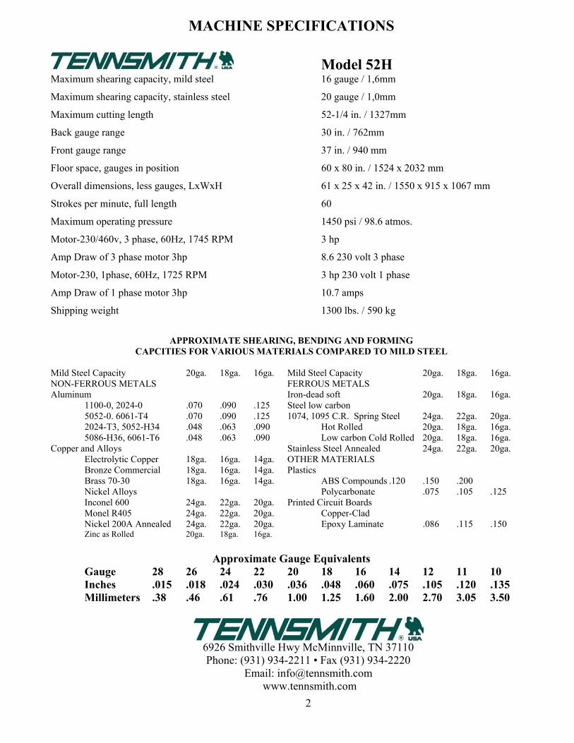
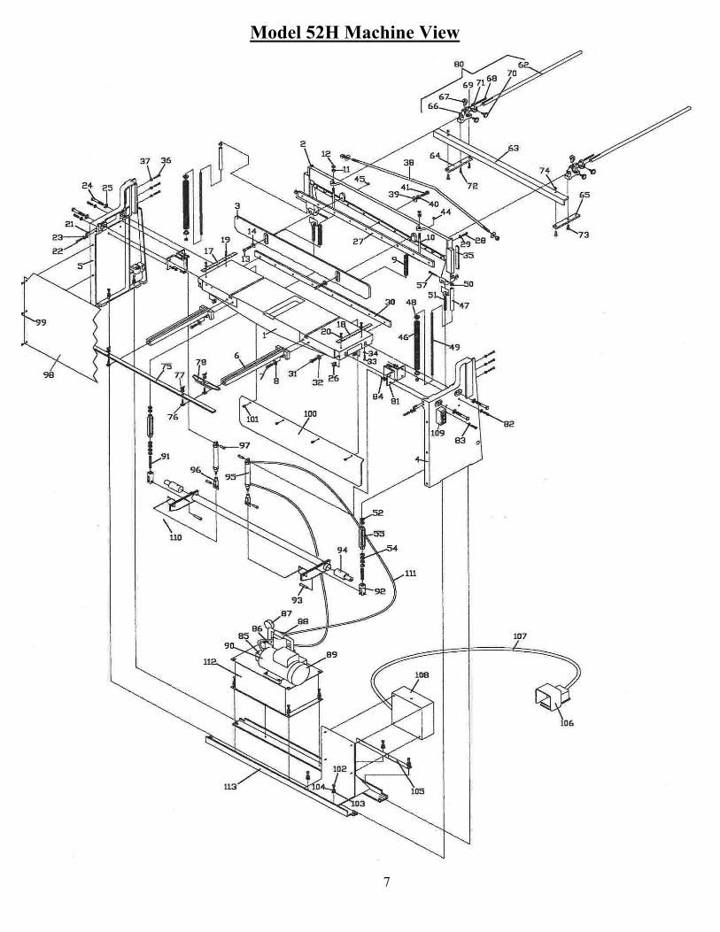
OPERATION INSTRUCTIONS The mild steel capacity of the Model 52H shear is 16gauge. Included in the manual is a standard shearing, bending, and forming conversion chart for various materials including Aluminum, Stainless, and Plastics. If you have any capacity related questions on materials that do not appear on the chart, please contact Tennsmith technical support to help determine the exact capacity ratings. NEVER ATTEMPT TO SHEAR ANY MATERIAL GREATER THAN THE MAXIMUM RATING FOR YOUR SHEAR. The 52H is a fixed angle designed machine. Reducing the maximum width of your material does not increase the capacity rating of this shear. NEVER ATTEMPT TO SHEAR ANY MATERIAL WHICH WOULD BE LESS THAN A ½” CUT ACROSS THE FULL LENGTH OF THE TABLE UNDER FULL CAPACITY. The model 52H is equipped with a start/stop Power switch (Part #109) located on the right side panel of the shear facing from the front. Press the green start button to engage the hydraulics and start the shear. Your machine is now ready to shear. To activate the cutter bar (Part #2); press the footswitch (part #106).
5
BLADE GAP ADJUSTMENT The factory setting for the gap between the upper and lower blade is .002. This setting is the optimal clearance for the entire range of material likely to be sheared on this machine. Different materials and thickness may require a larger or slightly smaller clearance. If you have any specific questions regarding optimal blade gap, please consult Tennsmith. To adjust the blade gap of your shear, the turnbuckles (55) are utilized to move the cutter bar down and hold the position while the blade adjustment is being made. Please note: when checking the blade clearance between the blades at any particular point across the travel of the bed, check the gap at the point where the upper blade intersects the lower blade by 1/8” depth.
To start, disconnect the main power connection to the shear.
1. Loosen the jam nuts (54) that lock the turnbuckle in position. 2. Move the cutter bar down by tightening each turnbuckle. To avoid putting the cutter bar in a bind, tighten
each turnbuckle evenly. The first checkpoint when verifying or changing the blade gap is 2 inches from the right side end of the blade facing the machine. Make sure the upper blade intersects the lower blade by 1/8”. Once you have moved the cutter bar into the desired position, use a set of shim feeler gauges to verify the blade clearance between the two blades. The second checkpoint is the center of the shear, and the last is 2 inches from the left end of the blades.
3. To close the gap on the either the left or the right ends of the blade, loosen the table bolts(24) for the particular end you are adjusting, and loosen the 9/16” adjustment screw (22) located in the front of your side panel by a ¼ turn. Next tighten the set screw (21) to move the lower blade towards the upper blade. When you have reached the desired gap verified by your feeler gauge, tighten the adjustment screw (22) to ensure the proper tension on the set screw. To open the gap, reverse the previous procedure.
4. After you have reached the desired gap, tighten the table bolts (24) on each side. 5. The blade gap in the center of the shear is controlled by the adjustment screw (40) located on the backside
of the cutter bar of the shear. To close the gap, tighten the screw in ¼ increments until you have reached the desired gap.
6. After you have adjusted the shear gap to the desired settings, move the cutter bar back to its original settings. This is called the pitch or rake of the blade:
Rake angle settings: Use a marker to mark the shear bed 2 inches to the from the right side edge of the table. Next, measure over 48 inches from the right side edge of the table and make another mark. Starting at the right hand side (facing the machine) at the designated mark on the table, rotate the turnbuckle (55) until the distance between the top and bottom blades is approximately 3/8 of an inch. At the opposing end, repeat the procedure allowing 1 ¾ inches clearance between the upper and lower blades. After you have the desired clearance between the upper and lower blades slightly adjust the turnbuckles so that they have an equal amount of tension. That is, if one turnbuckle has more play or lost motion in it than the other, it should be readjusted accordingly. Once the rake has been set and equal tension verified between the turnbuckles, retighten the jam nuts (54) and lock the turnbuckles in place.
HOLD-DOWN ADJUSTMENT
CAUTION: THIS SHEAR SHOULD NOT BE OPERATED WITHOUT THE HOLDDOWN IN PLACE AND PROPERLY ALIGNED. The hold-down (3) is designed to engage the material before the blades yet allow only minimal clearance between the guard’s feet and the table surface. The gap between the hold-down feet and table surface should never be above 3/16” of an inch. The gap between the hold-down and the table is controlled by turning the nut on the hold-down studs (10). Clockwise rotation will increase clearance; counter clockwise turns will decrease the gap. The guard should be held snug against the milled pads on the cutter bar and not feel loose. You must be careful, however, that the hold-down bolts (13) are not so tight as to bind the guard when the cutter bar is in the down position. Properly aligned, the bolts will snug but still allow rotation of the hold-down bolt washers (14). At the rear of the cutter bar you will find two tapped holes wherein hold-down jam screws (45) are located. Once you have applied proper tension to the hold-down bolts, tighten the jam screws to lock alignment in place. (Note: The milled pads on the front and rear of the hold-down should be greased periodically to maintain proper action.
6
BACK GAUGE ADJUSTMENT Slide back gauge rods (62) through the adjustment blocks (66) and brackets (71). Mount the rods in the holes found at the rear of the cutter bar. Move the gauge angle (63) up the rods until it contacts with the lower blade. Observe the pointers attached to the adjustment blocks and adjust the rods in or out until the embossed scales read zero on the pointers. Tighten the set screws (44) to lock the rods in place. To attain a particular setting, loosen the four lock screws (70) and slide the gauge to an approximate position. Fine tune adjustments are accomplished by locking the screws of the two adjustment brackets (71) while keeping those of the blocks (66) loose. The adjustment dial (68) can then be used to position the gauge in or out.
SHARPENING BLADES
Your TENNSMITH shear features “Tri-Action” ground blades. The upper blade has two cutting edges which are ground with a 2 degree edge relief. The upper blade can be turned over to expose the new cutting edge. It can be sharpened on a surface grinder by grinding both wide sides to the blade. The lower blade has one cutting edge with a 2 degree cutting edge relief and a 1 degree face relief. It can be sharpened on a surface grinder by grinding the wide side of the blade having the 1 degree relief. See Figure 2). Blade sharpening service is available from the factory.