1-800-366-5412 • www.encoder.com • [email protected]Rev. 03/22/18 FEATURES Slim Profile – Only 1.00" Deep Fits NEMA Size 56C Thru 184C Motor Faces (4.5" AK) Incorporates Opto-ASIC Technology Resoluons to 4096 CPR The Model 770 C-Face encoder is a rugged, high resolution encoder designed to mount directly on NEMA C-Face motors. Both sides of the encoder are C-Face mounts, allowing additional C-Face devices to be mounted to this encoder. Unlike many C-Face kit type encoders, the Model 770 contains precision bearings and an internal flex mount, virtually eliminating encoder failures and inaccuracies induced by motor shaft runout or axial endplay. The advanced Opto-ASIC design provides the advanced noise immunity necessary for many industrial applications. This encoder is ideal for applications using induction motors and flux vector control. The Model 770 provides speed and position information for drive feedback in a slim profile – only 1.00" thick. The Thru-Bore design allows fast and simple mounting of the encoder directly to the accessory shaft or to the drive shaft of the motor, using the standard motor face (NEMA sizes 56C - 184C). The tough, all-metal housing resists the vibration and hazards of an industrial environment. COMMON APPlICATIONS Motor Feedback, Velocity & Posion Control, Conveyors, Variable Speed Drives, Mixing & Blending Motors, Assembly & Specialty Machines MODEl 770 ORDERINg guIDE NOTES: 1 Thru-bore version may be IP65 sealed if mounted between two C-Face devices with optional gasket kit. Select 'Yes' under C-Face Gasket Kit Option. 2 Contact Customer Service for index gating options. 3 5 to 24 VDC max for high temperature option. 4 Line Driver Outputs not available with 5-pin M12 connector. Available with 7-pin MS connector only without Index Z. 5 For mating connectors, cables, and cordsets see Accessories at encoder.com. For Connector Pin Configuration Diagrams, see Technical Information or see Connector Pin Configuration Diagrams at encoder.com. 6 For non-standard cable lengths, add a forward slash (/) plus cable length expressed in feet. Example: P/6 = 6 feet of cable. 7 Please refer to Technical Bulletin TB100: When to Choose the CE Mark at encoder.com.. Blue type indicates price adder options. Not all configuration combinations may be available. Contact Customer Service for details. Ø6.5" MODEL 770 4.5" NEMA “AK" Dimension CYCLES PER REVOLUTION 1 - 4096 See CPR Options below for available resolutions. Price adder for CPR >1024 HOUSING STYLE A Cover completely encloses motor shaft and eliminates access to motor shaft; IP65 rated. Includes C-face Gasket Kit. B Thru-Bore housing version with IP50 dust seal 1 C-FACE GASKET KIT OPTION 1 "B" HOUSING ONLY N No Y Yes MATING CONNECTOR N No Connector Y Yes OUTPUT TYPE 5 - 28V In/Out 3 OC Open Collector PU Pull-Up Resistor PP Push-Pull HV Line Driver 4 NUMBER OF CHANNELS 2 Channel A Leads B Q Quadrature A & B R Quadrature A & B with Index Channel B Leads A K Reverse Quadrature A & B D Reverse Quadrature A & B with Index See http://www.encoder.com/ literature/index-phasing.pdf for additional options, and waveforms. A OC Q 1024 H A 770 N Y N CE OPERATING TEMPERATURE S 0° to 70° C H 0° to 100° C BORE SIZE A 5/8", 0.625" B 3/4", 0.750" C 7/8", 0.875" D 1", 1.000" H 14 mm I 19 mm K 24 mm CONNECTOR TYPE 5 P 24" Cable with Gland Nut 6 B Terminal Strip in Conduit Box X 10-pin MS on Conduit Box Y 7-pin MS on Conduit Box 4 J 5-pin M12 on Conduit Box 4 K 8-pin M12 on Conduit Box L 10-pin Industrial Clamp MODEl 770 CPR OPTIONS 0060 0100 0120 0240 0250 0256 0500 0512 1000 1024 2048 2500 4096 Contact Customer Service for other disk resolutions; not all disk resolutions available with all output types. CERTIFICATION N None CE CE Marked 7 MODEL 770 - INCREMENTAL ENCODER
F eat u r esSlim Profile – Only 1.00" DeepFits NEMA Size 56C Thru 184C Motor Faces (4.5" AK)Incorporates Opto-ASIC TechnologyResolutions to 4096 CPRThe Model 770 C-Face encoder is a rugged, high resolution encoder designed to mount directly on NEMA C-Face motors. Both sides of the encoder are C-Face mounts, allowing additional C-Face devices to be mounted to this encoder. Unlike many C-Face kit type encoders, the Model 770 contains precision bearings and an internal flex mount, virtually eliminating encoder failures and inaccuracies induced by motor shaft runout or axial endplay. The advanced Opto-ASIC design provides the advanced noise immunity necessary for many industrial applications. This encoder is ideal for applications using induction motors and flux vector control. The Model 770 provides speed and position information for drive feedback in a slim profile – only 1.00" thick. The Thru-Bore design allows fast and simple mounting of the encoder directly to the accessory shaft or to the drive shaft of the motor, using the standard motor face (NEMA sizes 56C - 184C). The tough, all-metal housing resists the vibration and hazards of an industrial environment.
CO M M O N A P P l I C AT I O N SMotor Feedback, Velocity & Position Control, Conveyors, Variable Speed Drives, Mixing & Blending Motors, Assembly & Specialty Machines
M O D E l 770 O R D E R I N g g u I D E
NOTES:1 Thru-bore version may be IP65 sealed if mounted between two C-Face devices with optional gasket kit.
Select 'Yes' under C-Face Gasket Kit Option.2 Contact Customer Service for index gating options.3 5 to 24 VDC max for high temperature option.4 Line Driver Outputs not available with 5-pin M12 connector. Available with 7-pin MS connector only
without Index Z.5 For mating connectors, cables, and cordsets see Accessories at encoder.com. For Connector Pin
Configuration Diagrams, see Technical Information or see Connector Pin Configuration Diagrams at encoder.com.
6 For non-standard cable lengths, add a forward slash (/) plus cable length expressed in feet. Example: P/6 = 6 feet of cable.
7 Please refer to Technical Bulletin TB100: When to Choose the CE Mark at encoder.com..
Blue type indicates price adder options. Not all configuration combinations may be available. Contact Customer Service for details.
Ø6.5"
MODEL770 4.5" NEMA
“AK" Dimension
CYCLES PER REVOLUTION
1 - 4096See CPR Options below for
available resolutions.Price adder for CPR >1024
HOUSING STYLEA Cover completely encloses motor
shaft and eliminates access to motor shaft; IP65 rated. Includes C-face Gasket Kit.
B Thru-Bore housing version with IP50 dust seal1
C-FACE GASKET KIT OPTION1
"B" HOUSING ONLYN NoY Yes
MATING CONNECTORN No ConnectorY Yes
OUTPUT TYPE5 - 28V In/Out3
OC Open CollectorPU Pull-Up ResistorPP Push-PullHV Line Driver 4
NUMBER OF CHANNELS2
Channel A Leads BQ Quadrature A & BR Quadrature A & B with IndexChannel B Leads AK Reverse Quadrature A & BD Reverse Quadrature A & B
with IndexSee http://www.encoder.com/literature/index-phasing.pdf for additional options, and waveforms.
AOCQ1024HA770 NY N CE
OPERATING TEMPERATURE
S 0° to 70° C H 0° to 100° C
BORE SIZEA 5/8", 0.625"B 3/4", 0.750"C 7/8", 0.875"D 1", 1.000"H 14 mm I 19 mmK 24 mm
CONNECTOR TYPE5
P 24" Cable with Gland Nut6
B Terminal Strip in Conduit BoxX 10-pin MS on Conduit BoxY 7-pin MS on Conduit Box4
J 5-pin M12 on Conduit Box4
K 8-pin M12 on Conduit BoxL 10-pin Industrial Clamp
M O D E l 770 C P R O P T I O N S0060 0100 0120 0240 0250 0256 0500 0512 1000 1024 2048 2500 4096Contact Customer Service for other disk resolutions; not all disk resolutions available with all output types.
CERTIFICATIONN NoneCE CE Marked7
M o d e l 7 7 0 - i n c r e M e n t a l e n c o d e r
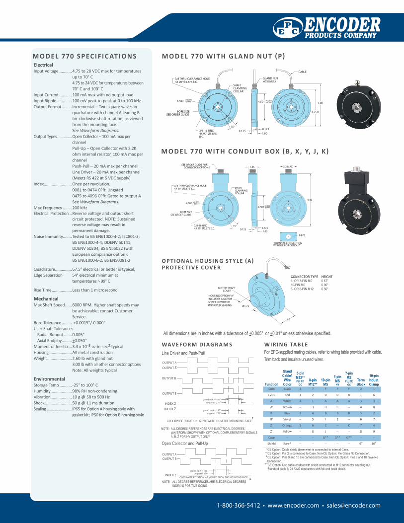
All dimensions are in inches with a tolerance of +0.005" or +0.01" unless otherwise specified.
WAV E FO R M D I Ag R A M S
C
PREV ASSEMBLY
ISSUE DATE
NEXT ASSEMBLY
MFG
PE
DATEDESCRIPTONLTR
REVISIONSCHK APPR DATE
77X LINE DRIVER OUTPUT WAVEFORM
LD770LRA N/A 1 1
OUTPUT A
OUTPUT B
NOTE: ALL DEGREE REFERENCES ARE ELECTRICAL DEGREESCLOCKWISE ROTATION
OUTPUT B
OUTPUT A
INDEX Z
INDEX Z
-
LD770LR
REV.
ENCODER PRODUCTS COMPANY
PART NUMBER+- .1˚ PRJ ENG
.01
TOLERANCE
.005+
ANGULAR
-+
DECIMAL
-
DECIMAL
DR
CK
QC
INITIAL
SCALEDWG SIZE
DWG NUMBER
NAME AND TITLEDATE
SHEET OF
- INITIAL RELEASE
02/11/03
BSR 02/11/03
gated to A = 180˚ungated 270˚
gated to A = 180˚ungated 270˚
Line Driver and Push-Pull
77X SINGLEENDED OUTPUT WAVEFORM
SE770LRA N/A 1 1
C
PREV ASSEMBLY
ISSUE DATE
NEXT ASSEMBLY
MFG
PE
DATEDESCRIPTONLTR
REVISIONSCHK APPR DATE
OUTPUT BOUTPUT A
CLOCKWISE ROTATION
NOTE: INDEX IS POSITIVE GOING
-
NOTE: ALL DEGREE REFERENCES ARE ELECTRICAL DEGREES
REV.
ENCODER PRODUCTS COMPANY
PART NUMBER+- .1˚ PRJ ENG
TOLERANCE
+
ANGULAR
-+
DECIMAL
-
DECIMAL
DR
CK
QC
INITIAL
SCALEDWG SIZE
DWG NUMBER
NAME AND TITLEDATE
SHEET OF
- INITIAL RELEASE
INDEX Z
SE770LR
02/11/03
BSR 02/11/03
ungated 270˚gated to A = 180˚
Open Collector and Pull-Up
NOTE: ALL DEGREE REFERENCES ARE ELECTRICAL DEGREES INDEX IS POSITIVE GOING
ElectricalInput Voltage ............4.75 to 28 VDC max for temperatures
up to 70° C 4.75 to 24 VDC for temperatures between 70° C and 100° C
Input Current ...........100 mA max with no output loadInput Ripple ..............100 mV peak-to-peak at 0 to 100 kHzOutput Format ......... Incremental – Two square waves in
quadrature with channel A leading B for clockwise shaft rotation, as viewed from the mounting face. See Waveform Diagrams.
Output Types ...............Open Collector – 100 mA max per channel Pull-Up – Open Collector with 2.2K ohm internal resistor, 100 mA max per channel Push-Pull – 20 mA max per channel Line Driver – 20 mA max per channel (Meets RS 422 at 5 VDC supply)
Index .........................Once per revolution. 0001 to 0474 CPR: Ungated 0475 to 4096 CPR: Gated to output A See Waveform Diagrams.
Max Frequency ........200 kHzElectrical Protection ..Reverse voltage and output short
circuit protected. NOTE: Sustained reverse voltage may result in permanent damage.
Quadrature ...............67.5° electrical or better is typical, Edge Separation 54° electrical minimum at
temperatures > 99° C
Rise Time .................. Less than 1 microsecond
MechanicalMax Shaft Speed ......6000 RPM. Higher shaft speeds may
be achievable; contact Customer Service.
Bore Tolerance ......... +0.0015"/-0.000"User Shaft Tolerances Radial Runout .......0.005" Axial Endplay .........+0.050" Moment of Inertia ...3.3 x 10-3 oz-in-sec2 typicalHousing ....................All metal constructionWeight ......................2.60 lb with gland nut
3.00 lb with all other connector options Note: All weights typical
EnvironmentalStorage Temp ........... -25° to 100° CHumidity...................98% RH non-condensingVibration...................10 g @ 58 to 500 HzShock ........................50 g @ 11 ms durationSealing .........................IP65 for Option A housing style with
gasket kit; IP50 for Option B housing style
11B NONE
REVISIONSLTR DESCRIPTION DATE
OFSHEET
DATE NAME AND TITLE
DWG NUMBER
DWG SIZE SCALE
EP
INITIAL
QC
CK
DR
DECIMAL
-
DECIMAL
+-
ANGULAR
+
TOLERANCE
PRJ ENG.1°-+MFGPART NUMBER
NEXT ASSEMBLY
ISSUE DATE
PREV ASSEMBLY
C ENCODER PRODUCTS COMPANY
REV.
770-CONN E
GDB 1/05/99.005
.01
MODEL 770 CONNECTOR
C ECO #01645 GMA
THIRD ANGLE PROJECTION
01/07/03
E ECO #05696 JP 02/17/09
1/11/99
3.2 MAX
�0.875
1.65
9.40
W/ HOLE FOR CONDUITTERMINAL CONNECTION770-CONN
3/8 THRU CLEARANCE HOLE4X 90° Ø5.875 B.C.
BORE SIZESEE ORDER GUIDE
SHAFTCLAMPINGCOLLAR
�4.500 +0.000-0.003
3/8-16 UNC4X 90° Ø5.875 B.C.
15°
4.501+0.002-0.000
0.1751.00
0.125
SEE ORDER GUIDE FORCONNECTOR OPTIONS
D ECO #01978 GMA 05/14/04M O D E l 770 W I T h CO N D u I T B Ox (B, x, Y, J , K)
O P T I O N A l h O u S I N g ST Y l E (A)P ROT EC T I V E COV E R
CONNECTOR TYPE HEIGHT6- OR 7-PIN MS 0.67"10-PIN MS 0.90"5- OR 8-PIN M12 0.50"
M O D E l 770 W I T h g l A N D N u T (P)
NOTE: ALL DEGREE REFERENCES ARE ELECTRICAL DEGREES. WAVEFORM ShOWN WITh OPTIONAL COMPLEMENTARY SIGNALS A, B, Z FOR hV OUTPUT ONLY.
Function
GlandCable†WireColor
5-pin M12++ PU, PP,
OC8-pin M12++
10-pin MS
7-pin MSHV
7-pin MS
PU, PP, OC
Term Block
10-pinIndust. Clamp
Com Black 3 7 F F F 2 1
+VDC Red 1 2 D D D 1 6
A White 4 1 A A A 3 3
A' Brown -- 3 H C -- 4 8
B Blue 2 4 B B B 5 2
B' Violet -- 5 I E -- 6 7
Z Orange 5 6 C -- C 7 4
Z' Yellow -- 8 J -- -- 8 9
Case -- -- -- G** G** G** -- --
Shield Bare* -- -- -- -- -- 9+ 10+
*CE Option: Cable shield (bare wire) is connected to internal Case.**CE Option: Pin G is connected to Case. Non-CE Option: Pin G has No Connection. +CE Option: Pins 9 and 10 are connected to Case. Non CE Option: Pins 9 and 10 have No
Connection.++CE Option: Use cable cordset with shield connected to M12 connector coupling nut.
†Standard cable is 24 AWG conductors with foil and braid shield.
W I R I N g TA B l EFor EPC-supplied mating cables, refer to wiring table provided with cable.Trim back and insulate unused wires.
CLOCKWISE ROTATION AS VIEWED FROM ThE MOUNTING FACE
CLOCKWISE ROTATION AS VIEWED FROM ThE MOUNTING FACE


![Get 642-770 exam questions & 642-770 practice tests [Infographic]](https://static.documents.pub/doc/80x56/58e7683a1a28ab147b8b46c5/get-642-770-exam-questions-642-770-practice-tests-infographic.jpg)


