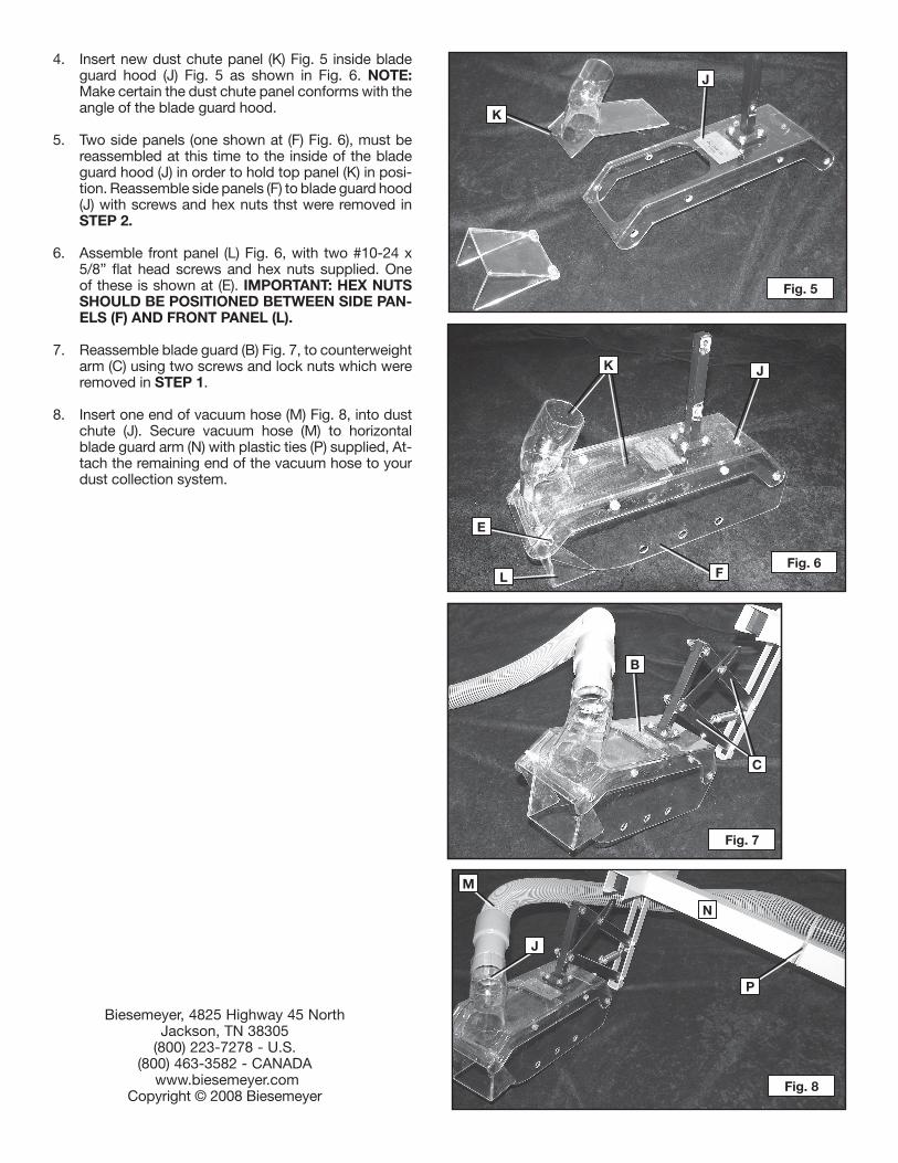
+ All Categories
Home > Documents > MODEL 78-966 ACCESSORY VACUUM …documents.dewalt.com/documents/English/Instruction Manual...model...

MODEL 78-966 ACCESSORY VACUUM …documents.dewalt.com/documents/English/Instruction Manual...model...

Date post: 26-Apr-2018
Category:
Upload: trinhduong
View: 214 times
Download: 0 times
Share this document with a friend
2
1348758 - 3-3-08 - Rev. B MODEL 78-966 ACCESSORY VACUUM ATTACHMENT FOR BIESEMEYER T-SQUARE BLADE GUARD SYSTEMS COMPONENTS (FIG. 1) ASSEMBLY IMPORTANT: MAKE CERTAIN THE MACHINE IS DIS- CONNECTED FROM THE POWER SOURCE AND LOWER THE SAW BLADE BELOW THE TABLE SUR- FACE. LOCK THE BLADE GUARD IN THE RAISED PO- SITION. 1. Loosen two screws and locknuts (A) Fig. 2, and re- move blade guard assembly (B) from counterweight arm (C). NOTE: Hardware will be used again to re- mount the blade guard assembly. 2. Remove eight flat head screws (three shown at D) and (one shown at E), Fig. 3, and hex nuts that are holding the side panel (F), front panel (not shown), and top panel (not show) to the blade guard hood (J). Remove screws and hex nuts on the opposite side of the blade guard hood. NOTE: Do not discard six screws (D) and hex nuts, as they will be used again to reassemble the blade guard. 3. Remove and discard front panel and top panel from the blade guard assembly, as shown in Fig. 4. The dust chute panel (2) Fig. 1 and front panel (5) Fig. 1 will replace these. Fig. 1 1. 1-3/4” O.D. Vacuum Hose 2. Dust Chute Panel 3. #10-24 Hex Nuts (2) 4. #10-24 x 5/8” Flat Head Screws (2) 5. Front Panel 6. Plastic Ties Fig. 2 Fig. 4 The Model 78-966 Accessory Vacuum Attachment Kit allows the capability of connecting a dust collection system to your Biesemeyer T-Square Blade Guard. It provides an effective method of keeping sawdust away from the table surface and qorkpiece without hindering your line of sight. The following instructions illustrate how to assemble the vacuum attachment to your current Biesemeyer T-Sqaure Blade Guard System. Fig. 3 2 1 3 6 4 5 A C D E F F B
Transcript

1348758 - 3-3-08 - Rev. B

MODEL 78-966 ACCESSORY VACUUM ATTACHMENT FOR BIESEMEYER T-SQUARE BLADE GUARD SYSTEMS

COMPONENTS (FIG. 1)

ASSEMBLYIMPORTANT: MAkE CERTAIN THE MACHINE IS DIS-CONNECTED FROM THE POwER SOURCE AND LOwER THE SAw BLADE BELOw THE TABLE SUR-FACE. LOCk THE BLADE GUARD IN THE RAISED PO-SITION. 1. Loosen two screws and locknuts (A) Fig. 2, and re-

move blade guard assembly (B) from counterweight arm (C). NOTE: Hardware will be used again to re-mount the blade guard assembly.

2. Remove eight flat head screws (three shown at D) and (one shown at E), Fig. 3, and hex nuts that are holding the side panel (F), front panel (not shown), and top panel (not show) to the blade guard hood (J). Remove screws and hex nuts on the opposite side of the blade guard hood. NOTE: Do not discard six screws (D) and hex nuts, as they will be used again to reassemble the blade guard.

3. Remove and discard front panel and top panel from the blade guard assembly, as shown in Fig. 4. The dust chute panel (2) Fig. 1 and front panel (5) Fig. 1 will replace these.

Fig. 11. 1-3/4” O.D. Vacuum Hose2. Dust Chute Panel3. #10-24 Hex Nuts (2)4. #10-24 x 5/8” Flat Head Screws (2)5. Front Panel6. Plastic Ties

Fig. 2

Fig. 4

The Model 78-966 Accessory Vacuum Attachment Kit allows the capability of connecting a dust collection system to your Biesemeyer T-Square Blade Guard. It provides an effective method of keeping sawdust away from the table surface and qorkpiece without hindering your line of sight. The following instructions illustrate how to assemble the vacuum attachment to your current Biesemeyer T-Sqaure Blade Guard System.

Fig. 3

2

1

36

4 5

A

C

DE

F F

B

Fig. 5

4. Insert new dust chute panel (K) Fig. 5 inside blade guard hood (J) Fig. 5 as shown in Fig. 6. NOTE: Make certain the dust chute panel conforms with the angle of the blade guard hood.

5. Two side panels (one shown at (F) Fig. 6), must be reassembled at this time to the inside of the blade guard hood (J) in order to hold top panel (K) in posi-tion. Reassemble side panels (F) to blade guard hood (J) with screws and hex nuts thst were removed in STEP 2.

6. Assemble front panel (L) Fig. 6, with two #10-24 x 5/8” flat head screws and hex nuts supplied. One of these is shown at (E). IMPORTANT: HEx NUTS SHOULD BE POSITIONED BETwEEN SIDE PAN-ELS (F) AND FRONT PANEL (L).

7. Reassemble blade guard (B) Fig. 7, to counterweight arm (C) using two screws and lock nuts which were removed in STEP 1.

8. Insert one end of vacuum hose (M) Fig. 8, into dust chute (J). Secure vacuum hose (M) to horizontal blade guard arm (N) with plastic ties (P) supplied, At-tach the remaining end of the vacuum hose to your dust collection system.

Biesemeyer, 4825 Highway 45 NorthJackson, TN 38305

(800) 223-7278 - U.S. (800) 463-3582 - CANADA

www.biesemeyer.comCopyright © 2008 Biesemeyer

Fig. 6

Fig. 7

Fig. 8

k

J

F

J

L

E

k

B

C

N

M

J

P


Recommended