Alexios Lekidis , Marius Bozga, Saddek Bensalem Univ. Grenoble Alpes, VERIMAG, F-38000 Grenoble, France CNRS, VERIMAG, F-38000 Grenoble, France 10 th IEEE International Workshop on Factory Communication Systems Paul Sabatier University, Toulouse (France) May 5-8,2014 Model-based validation of CANopen systems Lekidis A., Bozga M., Bensalem S. Model-based validation of CANopen systems 1/32
Transcript
Alexios Lekidis, Marius Bozga, Saddek Bensalem Univ. Grenoble Alpes, VERIMAG, F-38000 Grenoble, France
CNRS, VERIMAG, F-38000 Grenoble, France
10th IEEE International Workshop on Factory Communication Systems
Paul Sabatier University, Toulouse (France) May 5-8,2014
Model-based validation of CANopen systems
Lekidis A., Bozga M., Bensalem S. Model-based validation of CANopen systems 1/32
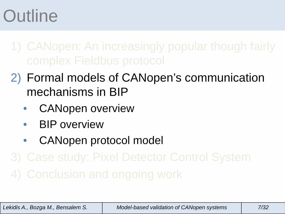
1) CANopen: An increasingly popular though fairly complex Fieldbus protocol
2) Formal models of CANopen’s communication mechanisms in BIP
• CANopen overview • BIP overview • CANopen protocol model
3) Case study: Pixel Detector Control System 4) Conclusion and ongoing work
Outline
Lekidis A., Bozga M., Bensalem S. Model-based validation of CANopen systems 2/32
Networked embedded systems (1)
Fieldbus protocols
• Manageable system complexity • Reduced communication cost and energy
consumption • Guarantee for functional and real-time requirements
Lekidis A., Bozga M., Bensalem S. Model-based validation of CANopen systems 3/32
Device 7
Device5
Device 3
Device 1
Device 6
Device 4
Device 2
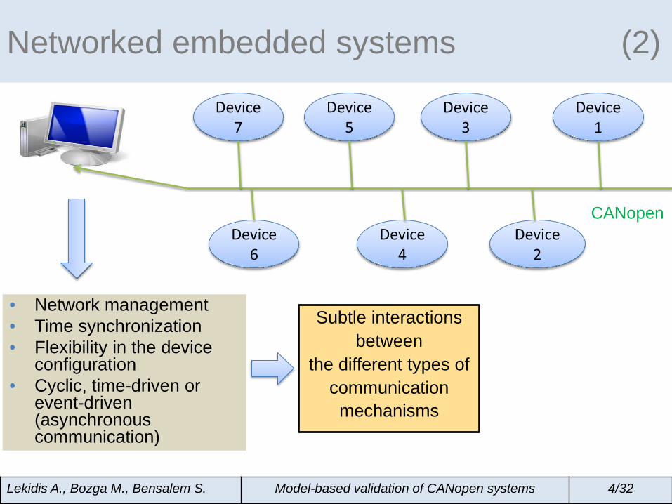
Networked embedded systems (2)
Device 7
Device5
Device 3
Device 1
Device 6
Device 4
Device 2
CANopen
Lekidis A., Bozga M., Bensalem S. Model-based validation of CANopen systems 4/32
• Network management • Time synchronization • Flexibility in the device
configuration • Cyclic, time-driven or
event-driven (asynchronous communication)
Device 7
Device5
Device 3
Device 1
Device 6
Device 4
Device 2
CANopen
Lekidis A., Bozga M., Bensalem S. Model-based validation of CANopen systems 4/32
Subtle interactions between
the different types of communication
mechanisms
Networked embedded systems (2)
• Network management • Time synchronization • Flexibility in the device
configuration • Cyclic, time-driven or
event-driven (asynchronous communication)
Lekidis A., Bozga M., Bensalem S. Model-based validation of CANopen systems 4/32
Device 7
Device5
Device 3
Device 1
Device 6
Device 4
Device 2
CANopen
• Network management • Time synchronization • Flexibility in the device
configuration • Cyclic, time-driven or
event-driven (asynchronous communication)
Subtle interactions between
the different types of communication
mechanisms
Functional system
construction is complex and
requires validation
Networked embedded systems (2)
Validation through conformance testing
Verifies the network integrity
Ensures the error-free functionality of a communication protocol
Observation of functional errors Early-stage performance analysis
Lekidis A., Bozga M., Bensalem S. Model-based validation of CANopen systems 5/32
Previous work is based on the analysis and validation of the CANopen communication profile through a number of test sections, related to: Object Dictionaries of the devices Conformance to the CANopen protocol Correct behavior in different network states as well as state transitions
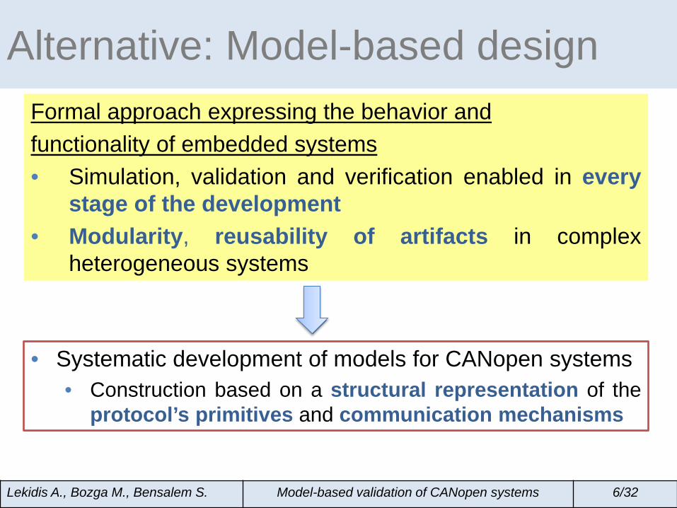
Alternative: Model-based design Formal approach expressing the behavior and functionality of embedded systems • Simulation, validation and verification enabled in every
stage of the development • Modularity, reusability of artifacts in complex
heterogeneous systems
• Systematic development of models for CANopen systems
• Construction based on a structural representation of the protocol’s primitives and communication mechanisms
Lekidis A., Bozga M., Bensalem S. Model-based validation of CANopen systems 6/32
1) CANopen: An increasingly popular though fairly complex Fieldbus protocol
2) Formal models of CANopen’s communication mechanisms in BIP
• CANopen overview • BIP overview • CANopen protocol model
3) Case study: Pixel Detector Control System 4) Conclusion and ongoing work
Outline
Lekidis A., Bozga M., Bensalem S. Model-based validation of CANopen systems 7/32
CANopen overview (1)
• Usage in a wide range of applications including: • Distributed control systems, building automation systems,
medical devices, photovoltaic systems, maritime electronics e.t.c.
• Fieldbus protocol based on a vast variety of standards: 1) Defining the communication mechanisms 2) Facilitating the configuration of:
• Applications, network devices, interfaces • Relying on different communication models, each one
corresponding to a specific protocol service: • Master/slave for management services • Client/server for configuration services • Producer/consumer for real-time communication services
Lekidis A., Bozga M., Bensalem S. Model-based validation of CANopen systems 8/32
CANopen overview (2)
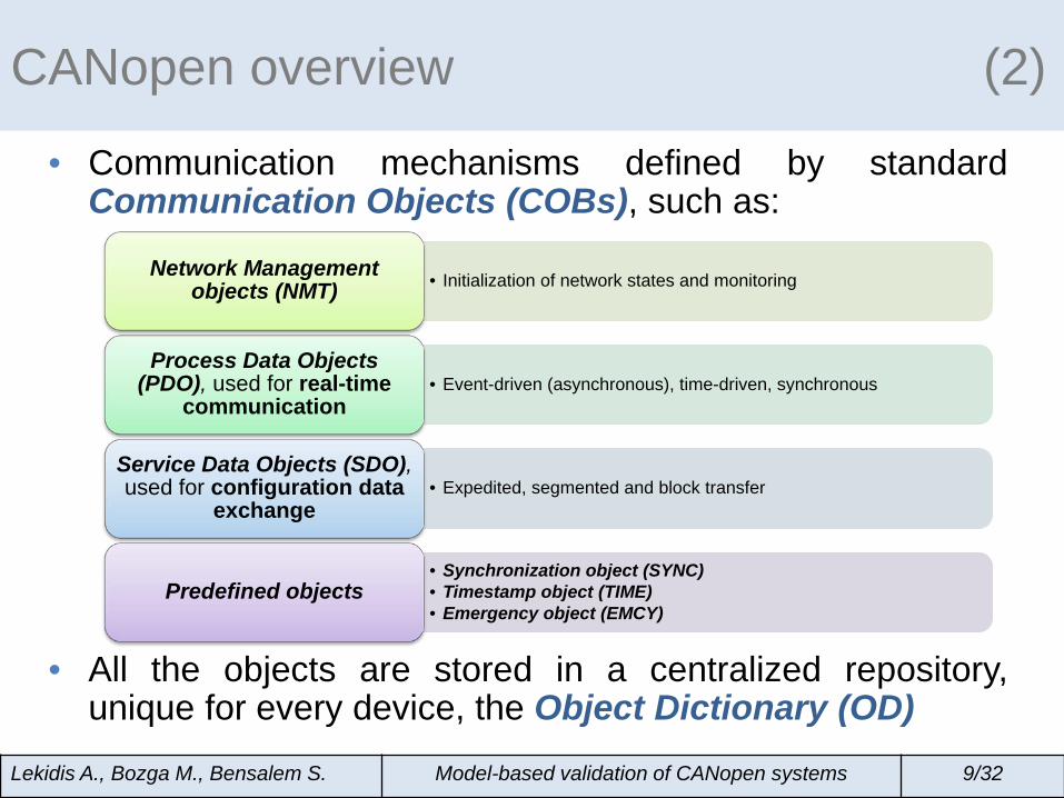
• Communication mechanisms defined by standard Communication Objects (COBs), such as:
• All the objects are stored in a centralized repository, unique for every device, the Object Dictionary (OD)
Lekidis A., Bozga M., Bensalem S. Model-based validation of CANopen systems 9/32
• Initialization of network states and monitoring Network Management objects (NMT)
• Event-driven (asynchronous), time-driven, synchronous Process Data Objects
(PDO), used for real-time communication
• Expedited, segmented and block transfer Service Data Objects (SDO), used for configuration data
Lekidis A., Bozga M., Bensalem S. Model-based validation of CANopen systems 10/32
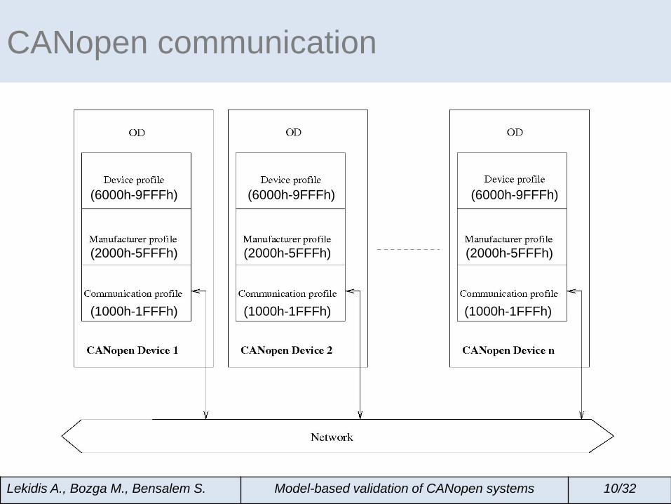
(6000h-9FFFh)
(1000h-1FFFh)
(6000h-9FFFh) (6000h-9FFFh)
(1000h-1FFFh) (1000h-1FFFh)
(2000h-5FFFh) (2000h-5FFFh) (2000h-5FFFh)
CANopen communication
Lekidis A., Bozga M., Bensalem S. Model-based validation of CANopen systems 10/32
(6000h-9FFFh)
(2000h-5FFFh)
(1000h-1FFFh)
(6000h-9FFFh) (6000h-9FFFh)
(2000h-5FFFh)
(1000h-1FFFh)
(2000h-5FFFh)
(1000h-1FFFh)
1st TPDO communication parameter
TPDO1
CANopen communication
Lekidis A., Bozga M., Bensalem S. Model-based validation of CANopen systems 10/32
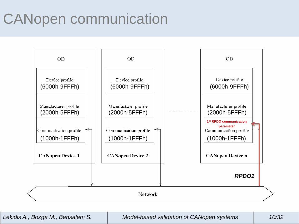
(6000h-9FFFh)
(1000h-1FFFh)
(6000h-9FFFh) (6000h-9FFFh)
(1000h-1FFFh) (1000h-1FFFh)
RPDO1
(2000h-5FFFh) (2000h-5FFFh) (2000h-5FFFh) 1st RPDO communication
parameter
• BIP (Behavior-Interaction-Priority) is a formal language for the hierarchical construction of heterogeneous real-time systems
• Provides a rich set of tools for analysis and
performance evaluation
B E H A V I O R
Interactions (collaboration)
Priorities (conflict resolution)
BIP component framework
Composition glue
Atomic components
Lekidis A., Bozga M., Bensalem S. Model-based validation of CANopen systems 11/32
s:=0 t:=0
BIP: Atomic components Finite state automata (Petri nets) extended with data and
functions described in C/C++
TICK
SEND s:=s+1
t:=0
COM [s<100]
TICK [t<100] t:=t+1
s SEND
idle
COM TICK
EXE RECV print(r)
TICK t:=t+1
r RECV
idle
EXE
TICK t:=t+1
Lekidis A., Bozga M., Bensalem S. Model-based validation of CANopen systems 12/32
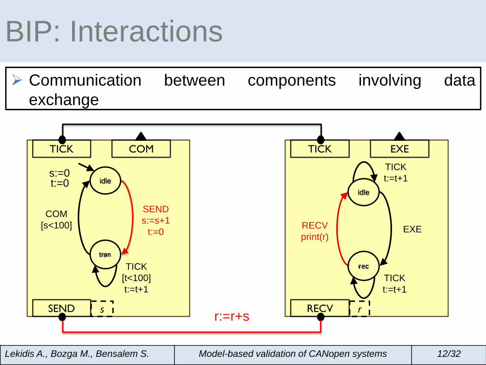
BIP: Interactions Communication between components involving data
exchange
s:=0 t:=0
TICK
SEND s:=s+1
t:=0
COM [s<100]
TICK [t<100] t:=t+1
s SEND
idle
COM TICK
EXE RECV print(r)
TICK t:=t+1
r RECV
idle
EXE
TICK t:=t+1
r:=r+s
Lekidis A., Bozga M., Bensalem S. Model-based validation of CANopen systems 12/32
BIP: Priorities Used among competing interactions
π1 : TICK<EXE
s:=0 t:=0
TICK
SEND s:=s+1
t:=0
COM [s<100]
TICK [t<100] t:=t+1
s SEND
idle
COM TICK
EXE RECV print(r)
TICK t:=t+1
r RECV
idle
EXE
TICK t:=t+1
r:=r+s
Lekidis A., Bozga M., Bensalem S. Model-based validation of CANopen systems 12/32
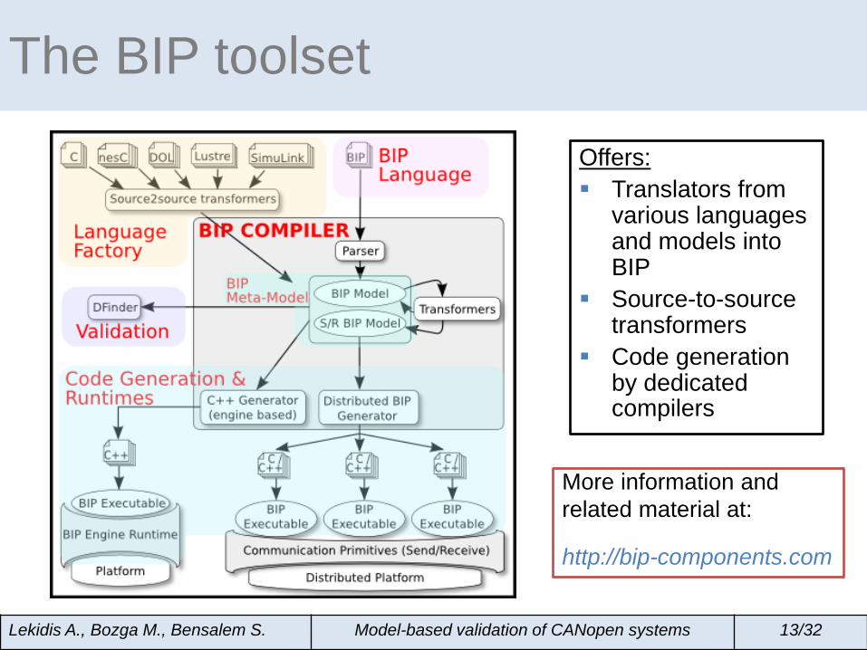
The BIP toolset
Offers: Translators from
various languages and models into BIP
Source-to-source transformers
Code generation by dedicated compilers
More information and related material at: http://bip-components.com
Lekidis A., Bozga M., Bensalem S. Model-based validation of CANopen systems 13/32
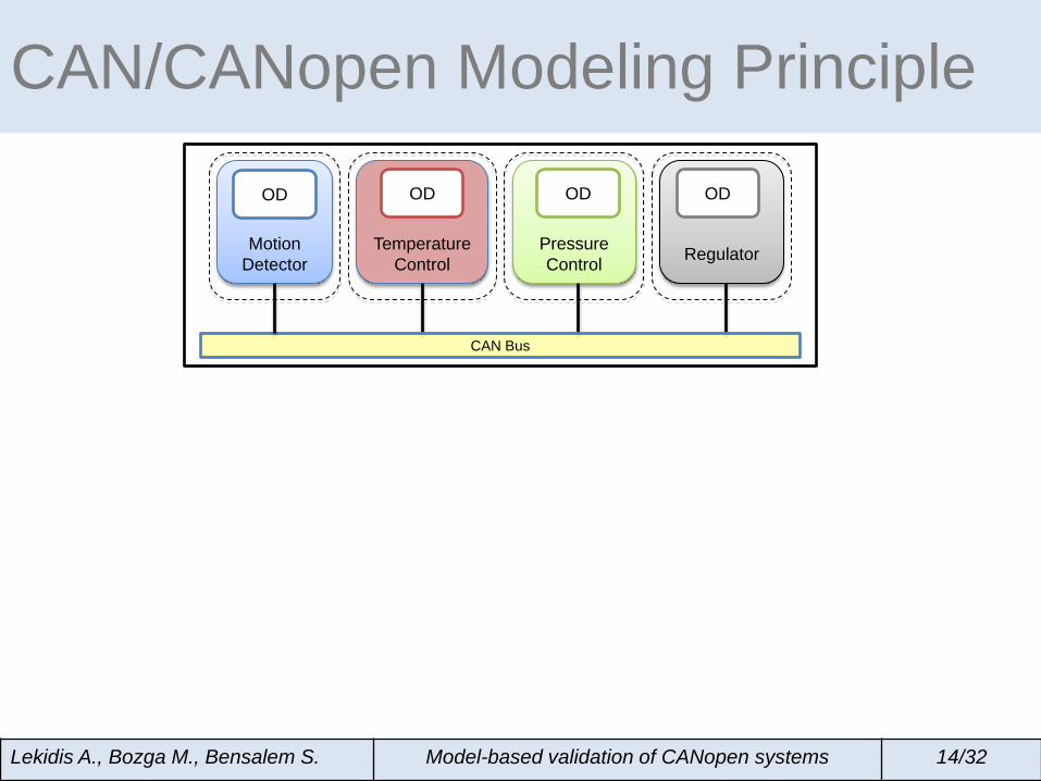
CAN/CANopen Modeling Principle
Lekidis A., Bozga M., Bensalem S. Model-based validation of CANopen systems 14/32
Temperature Control
Motion Detector
Pressure Control
Regulator
CAN Bus
OD OD OD OD
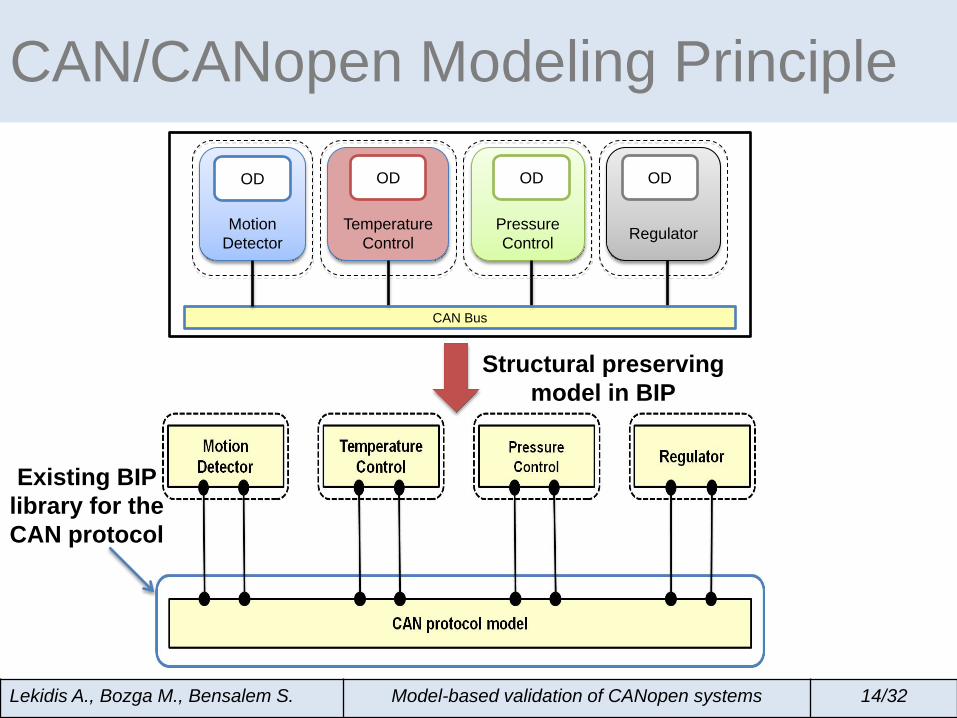
CAN/CANopen Modeling Principle
Lekidis A., Bozga M., Bensalem S. Model-based validation of CANopen systems 14/32
Temperature Control
Motion Detector
Pressure Control
Regulator
CAN Bus
OD OD OD OD
Existing BIP library for the CAN protocol
Structural preserving model in BIP
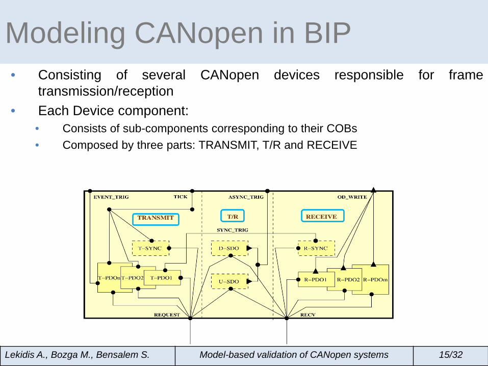
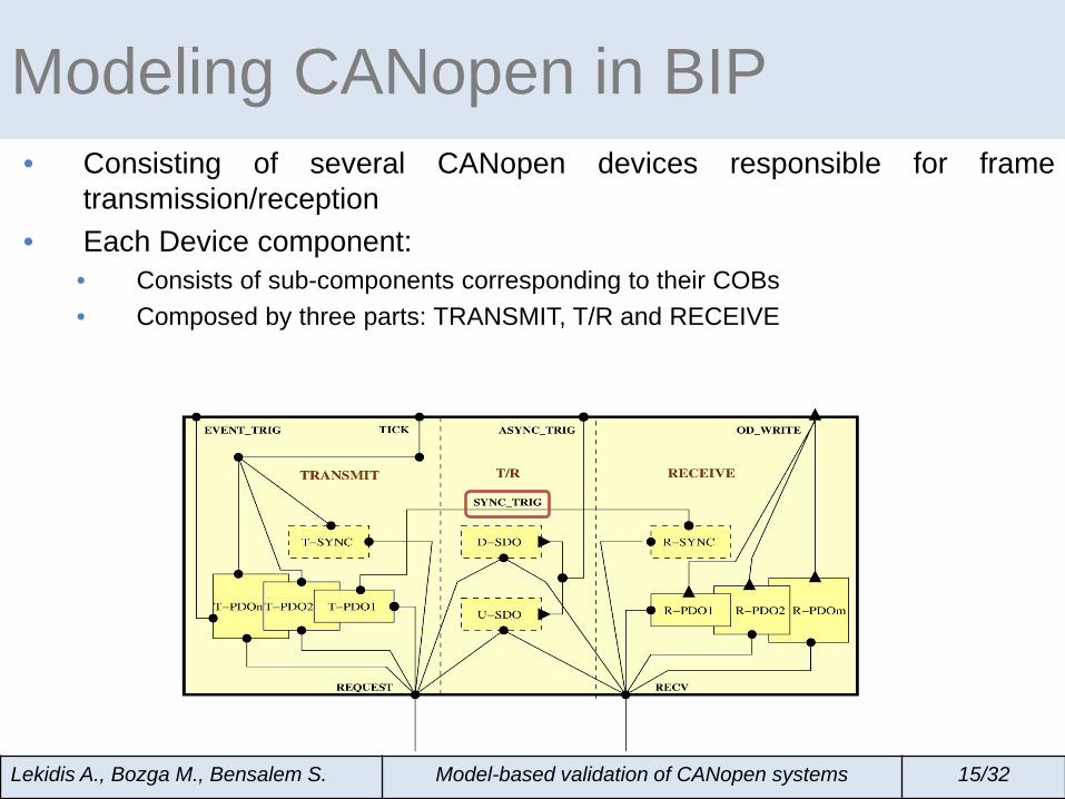
Modeling CANopen in BIP • Consisting of several CANopen devices responsible for frame
transmission/reception • Each Device component:
• Consists of sub-components corresponding to their COBs
Lekidis A., Bozga M., Bensalem S. Model-based validation of CANopen systems 15/32
Modeling CANopen in BIP • Consisting of several CANopen devices responsible for frame
transmission/reception • Each Device component:
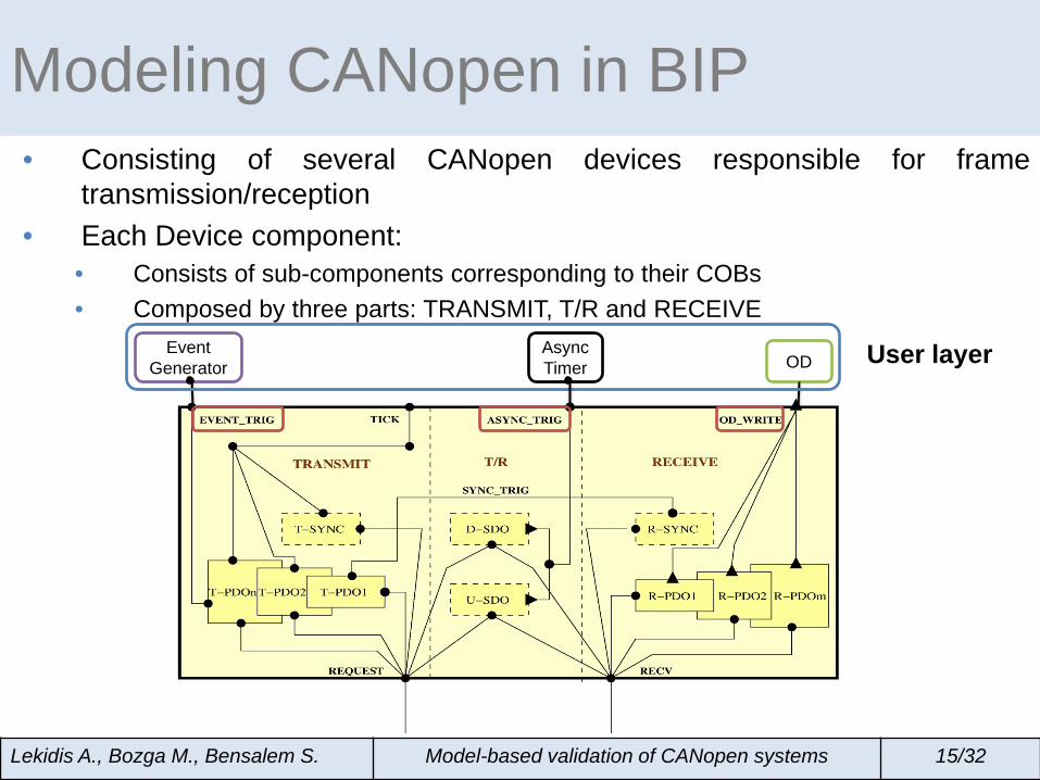
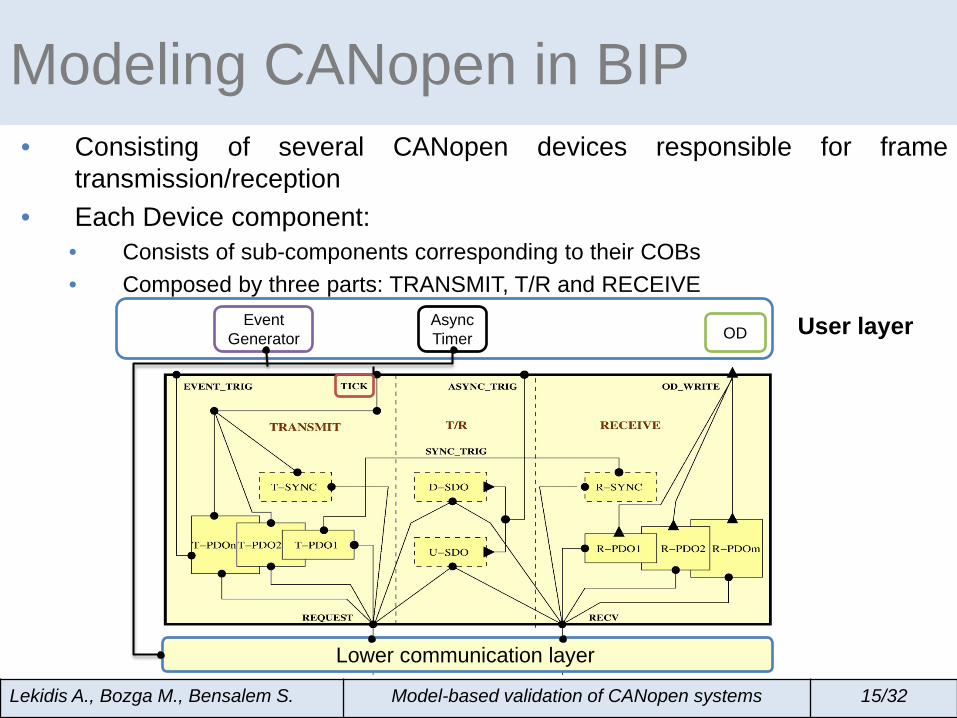
• Consists of sub-components corresponding to their COBs • Composed by three parts: TRANSMIT, T/R and RECEIVE
Lekidis A., Bozga M., Bensalem S. Model-based validation of CANopen systems 15/32
Modeling CANopen in BIP • Consisting of several CANopen devices responsible for frame
transmission/reception • Each Device component:
• Consists of sub-components corresponding to their COBs • Composed by three parts: TRANSMIT, T/R and RECEIVE
Lekidis A., Bozga M., Bensalem S. Model-based validation of CANopen systems 15/32
Lower communication layer
Modeling CANopen in BIP • Consisting of several CANopen devices responsible for frame
transmission/reception • Each Device component:
• Consists of sub-components corresponding to their COBs • Composed by three parts: TRANSMIT, T/R and RECEIVE
Lekidis A., Bozga M., Bensalem S. Model-based validation of CANopen systems 15/32
OD Async Timer
Event Generator User layer
Modeling CANopen in BIP • Consisting of several CANopen devices responsible for frame
transmission/reception • Each Device component:
• Consists of sub-components corresponding to their COBs • Composed by three parts: TRANSMIT, T/R and RECEIVE
Lekidis A., Bozga M., Bensalem S. Model-based validation of CANopen systems 15/32
Async Timer
Event Generator User layer
Lower communication layer
OD
• Divided in two categories the transmit PDO (T-PDO) and the receive PDO (R-PDO) component
• Supporting the following scheduling policies: • SYNC-triggered • Time-triggered • Event-triggered
PDO communication
Lekidis A., Bozga M., Bensalem S. Model-based validation of CANopen systems 16/32
SYNC-triggered T-PDO component
R-PDO component
idle
trig
REQUEST frame
SYNC_TRIG
REQUEST SYNC_TRIG id:=TPDO2
idle
rec
OD_WRITE
RECV frame
OD_WRITE [id:=TPDO2]
internal [id≠TPDO2]
RECV
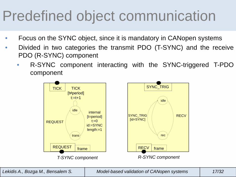
Predefined object communication • Focus on the SYNC object, since it is mandatory in CANopen systems • Divided in two categories the transmit PDO (T-SYNC) and the receive
PDO (R-SYNC) component • R-SYNC component interacting with the SYNC-triggered T-PDO
component
Lekidis A., Bozga M., Bensalem S. Model-based validation of CANopen systems 17/32
T-SYNC component R-SYNC component
REQUEST frame
TICK [t≠period]
t:=t+1
REQUEST
internal [t=period]
t:=0 id:=SYNC length:=1
idle
trans
SYNC_TRIG
idle
rec
RECV SYNC_TRIG [id=SYNC]
RECV frame
TICK
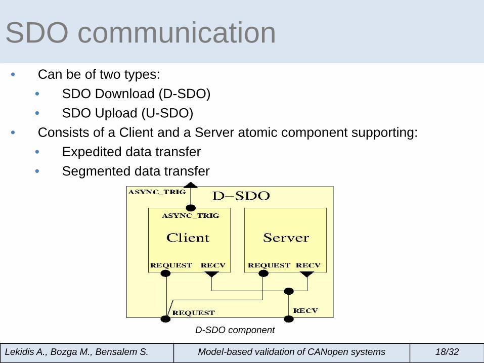
SDO communication • Can be of two types:
• SDO Download (D-SDO) • SDO Upload (U-SDO)
• Consists of a Client and a Server atomic component supporting: • Expedited data transfer • Segmented data transfer
Lekidis A., Bozga M., Bensalem S. Model-based validation of CANopen systems 18/32
D-SDO component
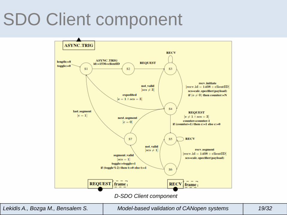
SDO Client component
Lekidis A., Bozga M., Bensalem S. Model-based validation of CANopen systems 19/32
D-SDO Client component
SDO Client component
Lekidis A., Bozga M., Bensalem S. Model-based validation of CANopen systems 19/32
D-SDO Client component
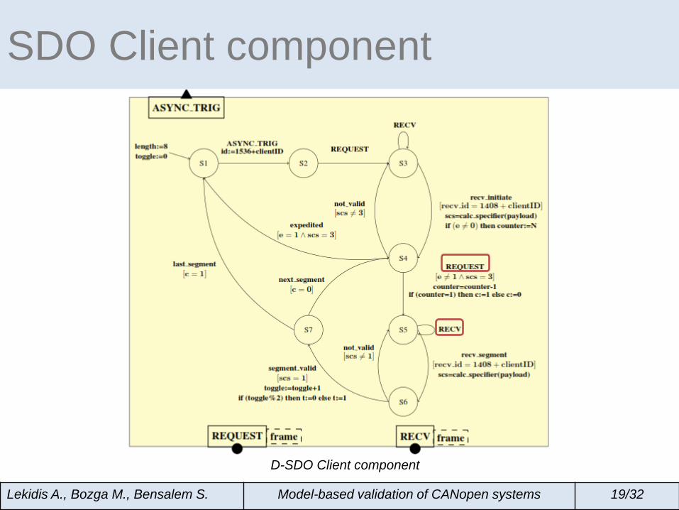
SDO Client component
Lekidis A., Bozga M., Bensalem S. Model-based validation of CANopen systems 19/32
D-SDO Client component
initiate segment
SDO Client component
Lekidis A., Bozga M., Bensalem S. Model-based validation of CANopen systems 19/32
D-SDO Client component
1) CANopen: An increasingly popular though fairly complex Fieldbus protocol
2) Formal models of CANopen’s communication mechanisms in BIP
• CANopen overview • BIP overview • CANopen protocol model
3) Case study: Pixel Detector Control System 4) Conclusion and ongoing work
Outline
Lekidis A., Bozga M., Bensalem S. Model-based validation of CANopen systems 20/32
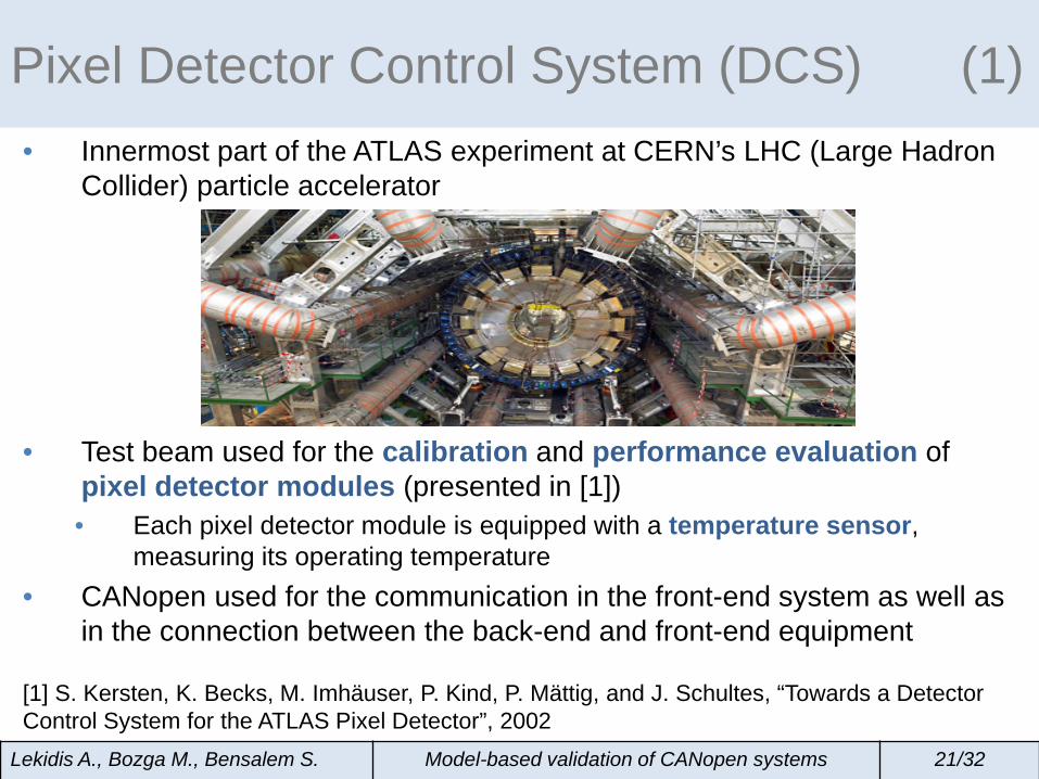
• Innermost part of the ATLAS experiment at CERN’s LHC (Large Hadron Collider) particle accelerator
• Test beam used for the calibration and performance evaluation of pixel detector modules (presented in [1]) • Each pixel detector module is equipped with a temperature sensor,
measuring its operating temperature • CANopen used for the communication in the front-end system as well as
in the connection between the back-end and front-end equipment [1] S. Kersten, K. Becks, M. Imhäuser, P. Kind, P. Mättig, and J. Schultes, “Towards a Detector Control System for the ATLAS Pixel Detector”, 2002
Lekidis A., Bozga M., Bensalem S. Model-based validation of CANopen systems 21/32
Pixel Detector Control System (DCS) (1)
Lekidis A., Bozga M., Bensalem S. Model-based validation of CANopen systems 22/32
Pixel Detector Control System (DCS) (2)
Lekidis A., Bozga M., Bensalem S. Model-based validation of CANopen systems 22/32
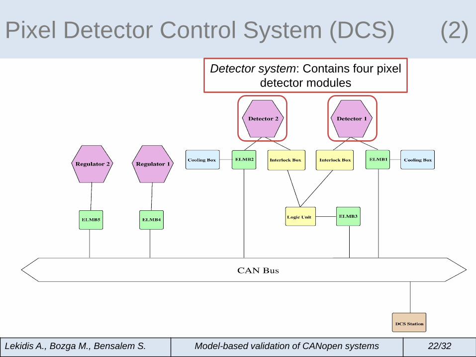
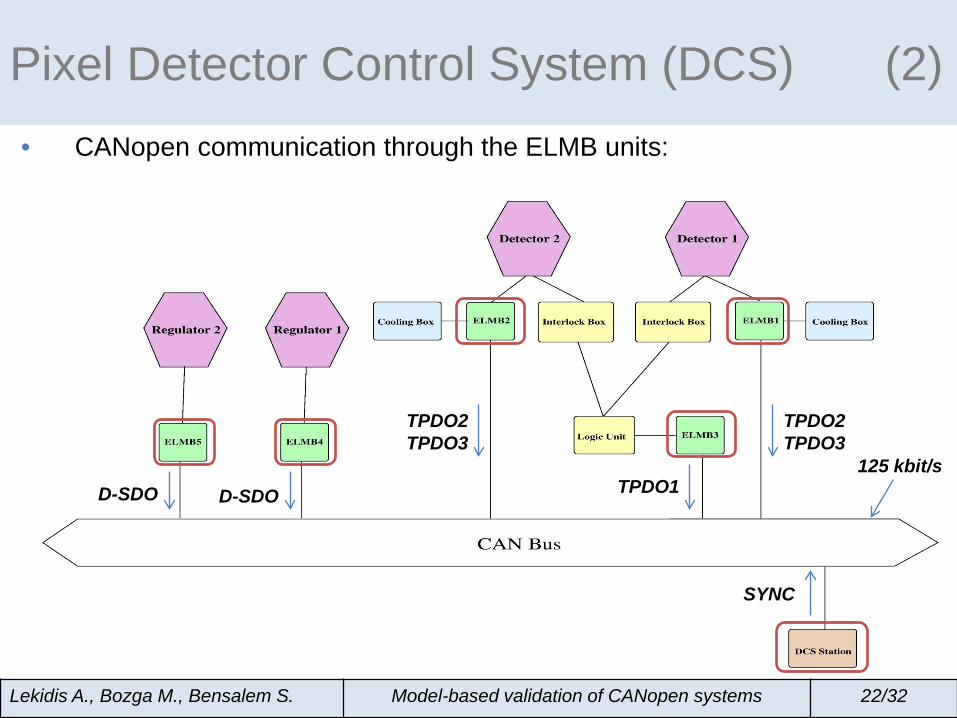
Pixel Detector Control System (DCS) (2) Detector system: Contains four pixel
detector modules
Lekidis A., Bozga M., Bensalem S. Model-based validation of CANopen systems 22/32
Pixel Detector Control System (DCS) (2)
Interlock Box: Thermal NFC system detecting the overheated pixel
detector modules
Lekidis A., Bozga M., Bensalem S. Model-based validation of CANopen systems 22/32
Pixel Detector Control System (DCS) (2)
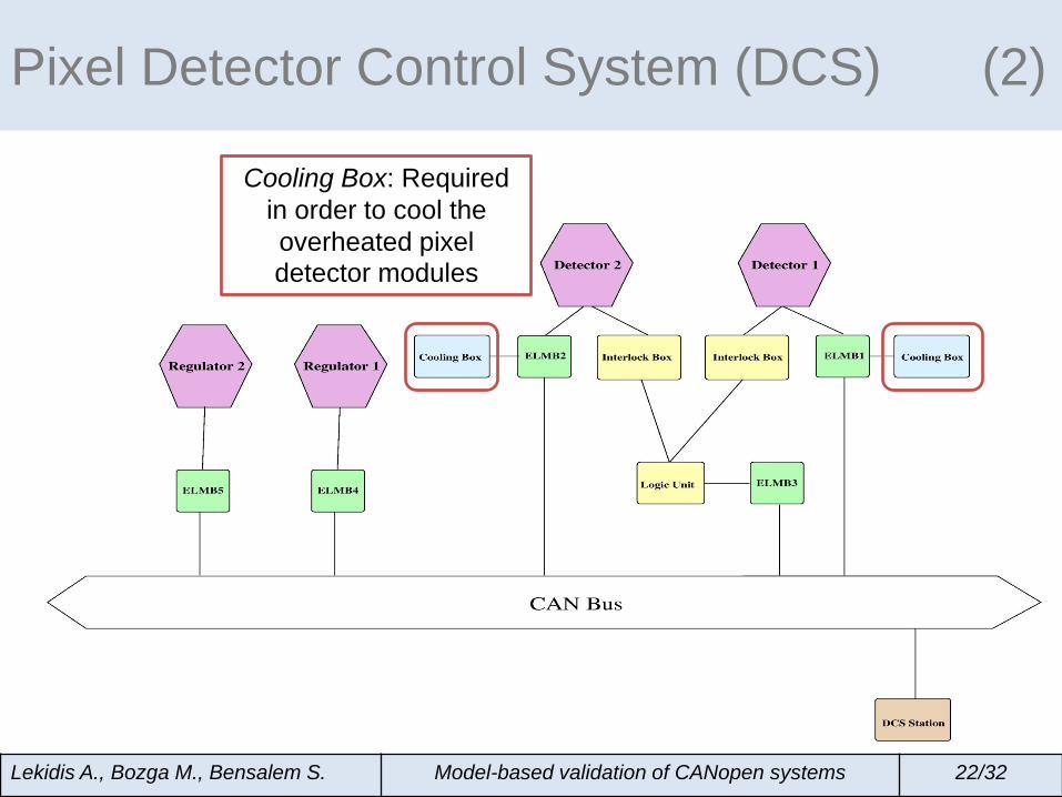
Cooling Box: Required in order to cool the overheated pixel detector modules
Lekidis A., Bozga M., Bensalem S. Model-based validation of CANopen systems 22/32
Pixel Detector Control System (DCS) (2)
Regulator: Adjusts the coolant flow inside the
Cooling Box
Lekidis A., Bozga M., Bensalem S. Model-based validation of CANopen systems 22/32
Pixel Detector Control System (DCS) (2)
DCS Station: Used for data logging, Ensuring synchronized data transmission
Lekidis A., Bozga M., Bensalem S. Model-based validation of CANopen systems 22/32
Pixel Detector Control System (DCS) (2)
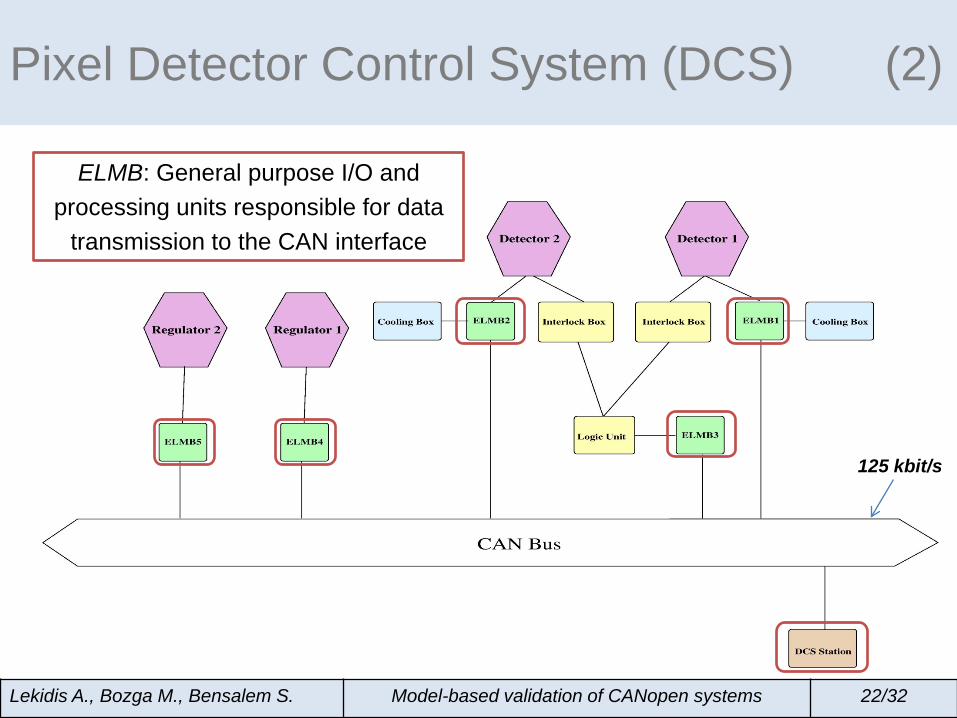
125 kbit/s
ELMB: General purpose I/O and processing units responsible for data
transmission to the CAN interface
• CANopen communication through the ELMB units:
Lekidis A., Bozga M., Bensalem S. Model-based validation of CANopen systems 22/32
Pixel Detector Control System (DCS) (2)
125 kbit/s
TPDO2TPDO3
TPDO2 TPDO3
TPDO1
SYNC
D-SDO D-SDO
Lekidis A., Bozga M., Bensalem S. Model-based validation of CANopen systems 23/32
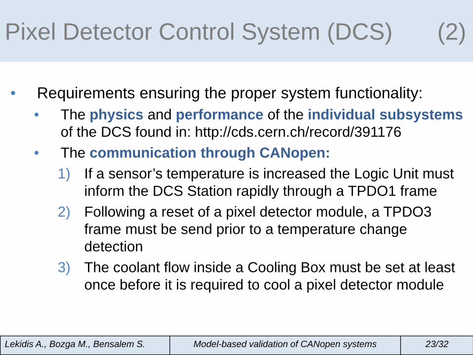
• Requirements ensuring the proper system functionality: • The physics and performance of the individual subsystems
of the DCS found in: http://cds.cern.ch/record/391176 • The communication through CANopen:
1) If a sensor’s temperature is increased the Logic Unit must inform the DCS Station rapidly through a TPDO1 frame
2) Following a reset of a pixel detector module, a TPDO3 frame must be send prior to a temperature change detection
3) The coolant flow inside a Cooling Box must be set at least once before it is required to cool a pixel detector module
Pixel Detector Control System (DCS) (2)
Lekidis A., Bozga M., Bensalem S. Model-based validation of CANopen systems 24/32
Lekidis A., Bozga M., Bensalem S. Model-based validation of CANopen systems 25/32
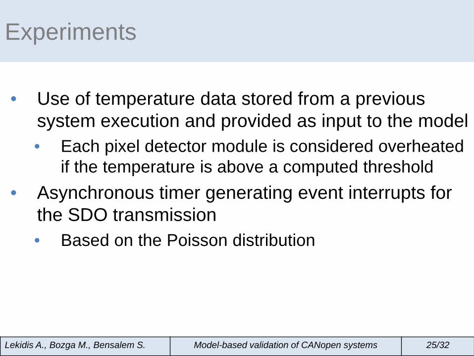
• Use of temperature data stored from a previous system execution and provided as input to the model • Each pixel detector module is considered overheated
if the temperature is above a computed threshold • Asynchronous timer generating event interrupts for
the SDO transmission • Based on the Poisson distribution
Experiments
Lekidis A., Bozga M., Bensalem S. Model-based validation of CANopen systems 26/32
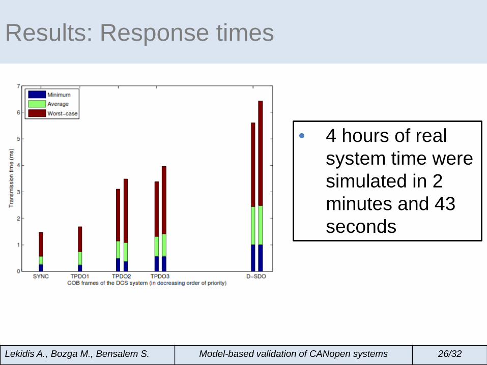
Results: Response times
• 4 hours of real system time were simulated in 2 minutes and 43 seconds
Lekidis A., Bozga M., Bensalem S. Model-based validation of CANopen systems 27/32
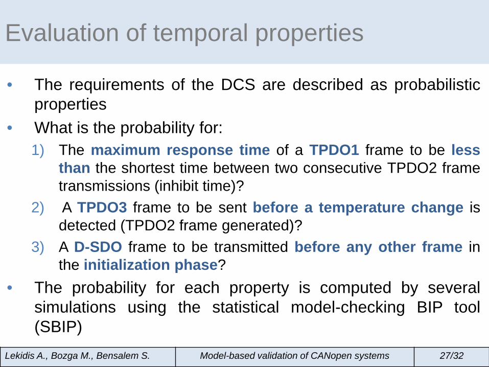
• The requirements of the DCS are described as probabilistic properties
• What is the probability for: 1) The maximum response time of a TPDO1 frame to be less
than the shortest time between two consecutive TPDO2 frame transmissions (inhibit time)?
2) A TPDO3 frame to be sent before a temperature change is detected (TPDO2 frame generated)?
3) A D-SDO frame to be transmitted before any other frame in the initialization phase?
• The probability for each property is computed by several simulations using the statistical model-checking BIP tool (SBIP)
Evaluation of temporal properties
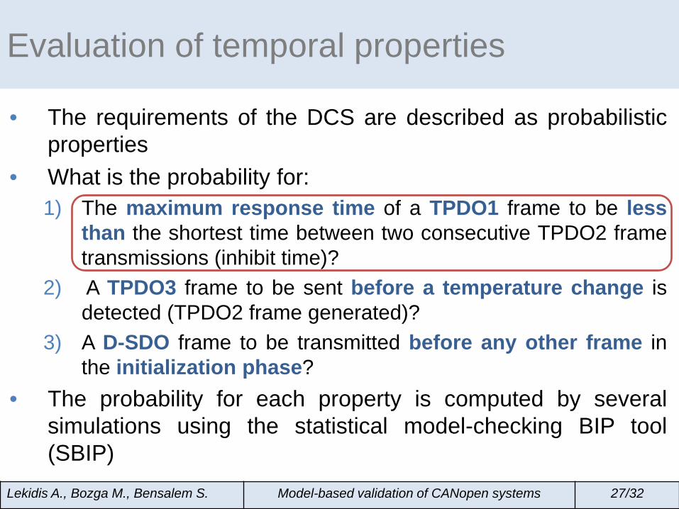
• The requirements of the DCS are described as probabilistic properties
• What is the probability for: 1) The maximum response time of a TPDO1 frame to be less
than the shortest time between two consecutive TPDO2 frame transmissions (inhibit time)?
2) A TPDO3 frame to be sent before a temperature change is detected (TPDO2 frame generated)?
3) A D-SDO frame to be transmitted before any other frame in the initialization phase?
• The probability for each property is computed by several simulations using the statistical model-checking BIP tool (SBIP)
Lekidis A., Bozga M., Bensalem S. Model-based validation of CANopen systems 27/32
Evaluation of temporal properties
Lekidis A., Bozga M., Bensalem S. Model-based validation of CANopen systems 28/32
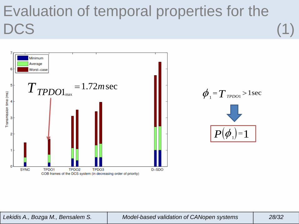
Evaluation of temporal properties for the DCS (1)
max1.72 sec1 mTPDOT =
111secTPDOTφ = >
( )1 1P φ =
• The requirements of the DCS are described as probabilistic properties
• What is the probability for: 1) The maximum response time of a TPDO1 frame to be less
than the shortest time between two consecutive TPDO2 frame transmissions (inhibit time)?
2) A TPDO3 frame to be sent before a temperature change is detected (TPDO2 frame generated)?
3) A D-SDO frame to be transmitted before any other frame in the initialization phase?
• The probability for each property is computed by several simulations using the statistical model-checking BIP tool (SBIP)
Lekidis A., Bozga M., Bensalem S. Model-based validation of CANopen systems 29/32
Evaluation of temporal properties
Lekidis A., Bozga M., Bensalem S. Model-based validation of CANopen systems 30/32
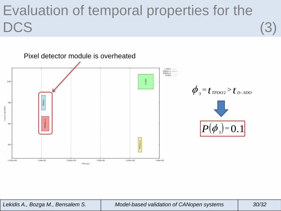
Evaluation of temporal properties for the DCS (3)
23 TPDO D SDOt tφ −= >
( )3 0.1P φ =
Pixel detector module is overheated
Conclusion • Systematic construction of formal models for
CANopen systems • Encapsulates both functional and extra-functional
aspects • Demonstration of the method on a case study • Validation of certain communication requirements
using the Statistical Model-Checking BIP tool • Ongoing work:
• Mapping of CANopen applications to Real-Time Ethernet networks
• Automatic code generation for Ethernet Powerlink based on CANopen specifications
Lekidis A., Bozga M., Bensalem S. Model-based validation of CANopen systems 31/32


![J1939 CANopen gateway - umu.se · J1939-CANopen gateway _____ 24 3 CANopen CANopen [3] is a higher layer protocol for CAN based networks. It is an offspring from CAL (see Section](https://static.documents.pub/doc/80x56/5e7174efe1907e55be07658a/j1939-canopen-gateway-umu-j1939-canopen-gateway-24-3-canopen-canopen-3.jpg)


