Model-based groupware solution for distributed real-time collaborative 4D planning via teamwork Article Accepted Version Zhou, W., Georgakis, P., Heesom, D. and Feng, X. (2012) Model-based groupware solution for distributed real-time collaborative 4D planning via teamwork. Journal of Computing in Civil Engineerin, 26 (5). pp. 597-611. ISSN 1943-5487 doi: https://doi.org/10.1061/(ASCE)CP.1943-5487.0000153 Available at https://centaur.reading.ac.uk/22752/ It is advisable to refer to the publisher’s version if you intend to cite from the work. See Guidance on citing . To link to this article DOI: http://dx.doi.org/10.1061/(ASCE)CP.1943- 5487.0000153 Publisher: American Society of Civil Engineers All outputs in CentAUR are protected by Intellectual Property Rights law, including copyright law. Copyright and IPR is retained by the creators or other copyright holders. Terms and conditions for use of this material are defined in the End User Agreement . www.reading.ac.uk/centaur
Transcript
Model-based groupware solution for distributed real-time collaborative 4D planning via teamwork Article
Accepted Version
Zhou, W., Georgakis, P., Heesom, D. and Feng, X. (2012) Model-based groupware solution for distributed real-time collaborative 4D planning via teamwork. Journal of Computing in Civil Engineerin, 26 (5). pp. 597-611. ISSN 1943-5487 doi: https://doi.org/10.1061/(ASCE)CP.1943-5487.0000153 Available at https://centaur.reading.ac.uk/22752/
It is advisable to refer to the publisher’s version if you intend to cite from the work. See Guidance on citing .
To link to this article DOI: http://dx.doi.org/10.1061/(ASCE)CP.1943-5487.0000153
Publisher: American Society of Civil Engineers
All outputs in CentAUR are protected by Intellectual Property Rights law, including copyright law. Copyright and IPR is retained by the creators or other copyright holders. Terms and conditions for use of this material are defined in the End User Agreement .
Central Archive at the University of Reading Reading’s research outputs online
Accep
ted M
anus
cript
Not Cop
yedit
ed
1
A model-based groupware solution for distributed real-time
collaborative 4D planning via teamwork
Wei Zhou1; Panagiotis Georgakis2; David Heesom3; Xiandong Feng4
Abstract
Construction planning plays a fundamental role in construction project management that
requires team working among planners from a diverse range of disciplines and in geographically
dispersed working situations. Model-based four-dimensional (4D) computer-aided design (CAD)
groupware, though considered a possible approach to supporting collaborative planning, is still short of
effective collaborative mechanisms for teamwork due to methodological, technological and social
challenges. Targeting this problem, this paper proposes a model-based groupware solution to enable a
group of multidisciplinary planners to perform real-time collaborative 4D planning across the Internet.
In the light of the interactive definition method, and its computer-supported collaborative work (CSCW)
design analysis, the paper discusses the realization of interactive collaborative mechanisms from
software architecture, application mode, and data exchange protocol. These mechanisms have been
integrated into a groupware solution, which was validated by a planning team in a truly geographically
dispersed condition. Analysis of the validation results revealed that the proposed solution is feasible for
real-time collaborative 4D planning to gain a robust construction plan through collaborative teamwork.
The realization of this solution triggers further considerations about its enhancement for wider
groupware applications.
Keywords: 4D CAD; collaborative construction planning; CSCW design; distributed groupware;
teamwork
1 Research Fellow, Design Innovation Research Centre, School of Construction Management
and Engineering, University of Reading, Whiteknights PO Box 225, Berkshire, RG6 6AW, United
Kingdom (corresponding author). E-mail: [email protected] 2 Senior Lecturer, School of Technology, University of Wolverhampton, Wulfruna Street,
Wolverhampton, WV1 1LY, United Kingdom. E-mail: [email protected] 3 Principal Lecturer, School of Technology, University of Wolverhampton, Wulfruna Street,
Wolverhampton, WV1 1LY, United Kingdom. E-mail: [email protected] 4 Lecturer, School of Design, Writtle College, Chelmsford, Essex, CM1 3RR, United
Journal of Computing in Civil Engineering. Submitted August 26, 2010; accepted July 28, 2011; posted ahead of print July 30, 2011. doi:10.1061/(ASCE)CP.1943-5487.0000153
Copyright 2011 by the American Society of Civil Engineers
Accep
ted M
anus
cript
Not Cop
yedit
ed
2
Introduction
Extensive studies have discussed four-dimensional (4D) computer-aided design (CAD) topics
in the construction field (Koo and Fischer 2000; Li et al. 2003; Dawood et al. 2005; Jongeling and
Olofsson 2006; Golparvar-Fard et al. 2009; Kim et al. 2010). Collier and Fischer (1996) initially
proposed to link a project plan with its 3D project model for simulating a construction sequence. In
such a way, potential conflicts can be discovered before the project delivery. Some industrial projects
such as the Walt Disney Concert Hall (Goldstain 2001) have demonstrated benefits adopting this 4D
(3D plus time) notion. Following this direction, research efforts have extended to the nD modeling
(University of Salford 2005) by applying advanced building information modeling (BIM) technology.
A series of case studies also discussed the effectiveness of BIM applications in the
Architecture/Engineering/Construction (AEC) field (Manning and Messner 2008; Khanzode et al,
2008; Pazlar and Turk 2008). Undoubtedly, these investigations are valuable in construction to analyze
multifactor relationships among the logical, temporal, and spatial dimensions using information
communication technology (ICT) tools. Despite their advancements in cutting-edge applications using
3D models (both CAD and BIM), none of the above examples have discussed model-based groupware
for distributed collaboration, which still remains challenges particularly in the fragmented construction
field for promoting multidisciplinary teamwork. For the purpose of investigating this area of work, this
paper discusses a model-based groupware solution targeting distributed real-time collaborative 4D
construction planning.
The construction industry has a multidisciplinary characteristic because of different specialties
involved before and during project delivery. 3D CAD/BIM technologies provide subcontractors with
possibilities to utilize a unique 3D building model throughout the project for multidisciplinary
collaboration (Ku et al. 2008). To enable this multiparty collaboration, synchronous and asynchronous
data access/control for the 3D model is essential. BIM solution providers demonstrate different
approaches to this functionality in their authoring tools. Autodesk creates worksets in its Revit products
such that project team members can work on different parts of a project at the same time (Autodesk
2010), while Bentley uses ‘i-model’ as a container for open information exchange (Bentley 2011).
Journal of Computing in Civil Engineering. Submitted August 26, 2010; accepted July 28, 2011; posted ahead of print July 30, 2011. doi:10.1061/(ASCE)CP.1943-5487.0000153
Copyright 2011 by the American Society of Civil Engineers
Accep
ted M
anus
cript
Not Cop
yedit
ed
3
Multidisciplinary collaborators can hence access this to share project information for integrated project
delivery. Gehry Technologies adopts the version control system of Subversion in its Digital Project
with which project models can be controlled over independent parts for team members’ read/write
operations (Gtwiki 2009). Tekla Structures applies the master/working model to realize model control
in its server/client applications (Tekla 2010). Although these model-based solutions allow multiple
users to concentrate on the 3D building model for collaboration, they merely aim at the low level of
model data integration and sharing. Beyond this data level’s collaboration, limited features are
available from them to promote multidisciplinary collaborators’ teamwork, which is more concerned
about human issues particularly in the distributed context (Grudin 1994; Shelbourn et al. 2007).
Construction project management calls for effective teamwork and synergy (Uher and
Loosemore 2004) whilst construction planning plays a fundamental role in project management
(Hendrickson 1998). However, a significant phenomenon in construction is that multidisciplinary
subcontractors of a project are often geographically dispersed before on-site work starts. Taking
construction planning into account, multidisciplinary planners in a planning team usually focus on their
own specialty work in different places. Their independent planning work inevitably causes conflicts
when integrated for the project delivery (Kang et al. 2007; Zhou et al. 2009). For overcoming this kind
of teamwork obstacle, 4D technology is highlighted for collaborative construction planning (Heesom
and Mahdjoubi 2004). An empirical study (Kang et al. 2007) shows that 4D simulation across the
Internet can help detect more conflicts in a construction plan. Thus networked collaborative 4D CAD
can benefit geographically dispersed planners’ work. The collaborative approach applying 4D is also
envisaged to improve other knowledge based work, e.g. 4D-BIM construction safety planning
(Sulankivi et al. 2010). Based on these initiatives, it is evident that a model-based 4D-planning
groupware can support a group of geographically dispersed planners to achieve a robust construction
plan through collaborative teamwork. Nevertheless, the realization of this groupware has three
challenges in methodological, technological and social aspects.
The methodological challenge is to properly address the relationship between 4D modeling
and planning in a networked environment. Since the initiation of 4D technology over a decade ago,
almost all studies and application solutions target stand-alone systems for individual planners. Their
Journal of Computing in Civil Engineering. Submitted August 26, 2010; accepted July 28, 2011; posted ahead of print July 30, 2011. doi:10.1061/(ASCE)CP.1943-5487.0000153
Copyright 2011 by the American Society of Civil Engineers
Accep
ted M
anus
cript
Not Cop
yedit
ed
4
typical methods of 4D CAD creation are to manually link an inputted 3D model with a developed
project plan. In such a way, elements of the 3D model – the product breakdown structure (PBS) can
connect with plan tasks – the work breakdown structure (WBS). 4D dynamic sequence simulation then
can be generated to review the plan using some third party toolkits such as Autodesk Navisworks,
Bentley ProjectWise Navigator, etc. This 4D CAD creation method needs separate tools for 3D
modeling, planning and 4D simulation. Despite adopting a 4D CAD functionality into 3D modeling
environments, commercially available BIM authoring tools, such as Tekla, Digital Project and others,
still require the user to input developed plan data to generate 4D CAD. Such a fragmented working
process is obviously inconvenient and ineffective, particularly in networked situations to integrate
various plan data from different planners. Targeting this problem, Sriprasert and Dawood (2003)
created the multi-constraint planning system that integrates plan data via a central database. The system
enables multiple users to access the database from the web and mobile platforms to remotely operate
plan data. Nonetheless, it applies the typical 4D CAD creation method to connect the developed plan
database with the inputted 3D model. This methodological limitation makes the system a collaborative
review system where multiple users can examine the developed plan being presented by the 4D CAD,
rather than a collaborative planning system where multiple users can engage in planning. Integrating
4D modeling into the planning process could be a viable approach to networked collaborative planning
for the 4D groupware creation.
Integrating 3D planning and 4D simulation gives rise to the technological challenge in the
network condition. Related studies show the possibility of using 3D CAD model directly for planning
(Frohlich 1997; Vries et al. 2007) and BIM model for 5D (4D plus cost) modeling (Tanyer and Aouad
2005) in the stand-alone situation. These research achievements invoke a further consideration that
collaborative 4D construction planning could be achieved by applying a 3D model underpinned by the
network infrastructure. Networked multidisciplinary planners can thus concentrate on a unique 3D
model to collaboratively perform construction planning, and generate 4D simulation to examine the
robustness of the plan during the planning. To satisfy these needs, the 4D groupware should own the
features of identifying and handling different data types, which come from multiple users when they
perform concurrent planning and take collaborative actions across the Internet. Synchro 4D as a
commercial application demonstrates its capability for concurrent planning. It uses a server/client
Journal of Computing in Civil Engineering. Submitted August 26, 2010; accepted July 28, 2011; posted ahead of print July 30, 2011. doi:10.1061/(ASCE)CP.1943-5487.0000153
Copyright 2011 by the American Society of Civil Engineers
Accep
ted M
anus
cript
Not Cop
yedit
ed
5
software architecture where the client application enables individual planners to perform 3D planning
and 4D modeling while the server application can integrate all plan data from clients (Synchro 2010).
Similar to the model-based BIM authoring tools discussed above, Synchro 4D only enables the user to
update and integrate plans at a data level. This system limitation hampers users from gaining sufficient
information with each other, and thus it is unlikely to turn their individual concurrent planning and 4D
modeling into collaborative teamwork.
Social dynamics brings challenges for collaborative teamwork in groupware development
(Grudin 1994). 4D groupware creation is particularly about supporting users’ tasks, behaviors and their
social activities as teamwork for problem solving in a shared 3D context. Zhou et al. (2009) highlighted
three levels of collaboration in the interactive definition method to deliver collaborative 4D planning
via teamwork. At a low level, generated plan and simulation data from multiple users can be integrated
similarly to Synchro 4D. At middle and high levels, multidisciplinary planners can use computer
systems to communicate and interact with each other directly and indirectly. In such a way, they can
organize and coordinate their individuals’ tasks and behaviors in the networked environment. This kind
of computer-supported collaborative work (CSCW) is essential to foster and motivate effective
collaboration across multidisciplinary boundaries to be interdisciplinary work (Fischer et al, 2005).
Fruchter (1999) highlighted that computer supported collaborative teamwork needs to be integrated
into system development to enhance networked information exchange and communication. Due to
these CSCW requirements from teamwork, the 4D groupware thus needs to provide a set of
mechanisms to satisfy team-based collaborative features and functionalities in analyzing a 3D model
for planning strategy exploration, coordinating planners’ communications and actions, etc.
Nevertheless, a survey shows that CSCW in the construction industry does not get deeper from the
current information-rich multidisciplinary work to the more creative interdisciplinary work (Garner
2003). The majority of popular model-based 3D/4D CAD/BIM solutions are usually short of related
collaborative mechanisms to support intimate teamwork. This disadvantage hampers the creation of
groupware solutions for more creative applications.
The aim of this paper is to discuss a model-based groupware solution for distributed real-time
collaborative 4D construction planning. It can enable multidisciplinary planners to focus on a unique
Journal of Computing in Civil Engineering. Submitted August 26, 2010; accepted July 28, 2011; posted ahead of print July 30, 2011. doi:10.1061/(ASCE)CP.1943-5487.0000153
Copyright 2011 by the American Society of Civil Engineers
Accep
ted M
anus
cript
Not Cop
yedit
ed
6
3D model to perform interdisciplinary collaborative planning across the boundaries of time, space, and
specialty. The innovation of this groupware solution lies in its collaborative mechanisms to handle
multilevel data for interactive and collaborative teamwork. Combining both social and technical
considerations, the paper firstly discusses the method and its underlying CSCW design of the
interactive collaboration in 4D construction planning. On the basis of this discussion, it further
proposes the groupware solution to disclose its collaborative mechanisms in terms of software
architecture, application mode and data flow, as well as data exchange protocol. This is accompanied
by the implemented prototype named 4DX and its application features. Furthermore, the paper
delineates the validation of the proposed solution conducted by a planning team in a truly
geographically distributed condition. Some unveiled insights in the validation contribute to the
discussion of further enhancement of the solution.
Method of Collaborative 4D Construction Planning
Collaborative 4D construction planning asks for multidisciplinary planners to perform, as a
team, planning work based on the network infrastructure. It needs contributions from individual
creativity and social creativity (Fischer et al. 2005). In order to achieve this aim, the interactive
definition method was created to involve individual planners for a real-time collaboration (Zhou et al.
2009). The method emphasizes an open shared social-technical context, social interaction, user-system
interaction and plan data incorporation. This section highlights the essence of 4D interactive
collaboration in the interactive definition method and further clarifies the principle of CSCW design in
the method.
Interactive Collaboration in 4D Planning
Collaborative 4D planning is a correlated social-technical activity. Its correlation includes
three levels of interaction in a social-technical context, in which inputting a unique 3D model is
essential to achieve this aim. Within such a context, social interaction among collaborators is available
via human-human communication at a high level. Multidisciplinary planners can communicate with
each other to discuss planning strategies and formulate planning solutions. User-system interaction, at a
Journal of Computing in Civil Engineering. Submitted August 26, 2010; accepted July 28, 2011; posted ahead of print July 30, 2011. doi:10.1061/(ASCE)CP.1943-5487.0000153
Copyright 2011 by the American Society of Civil Engineers
Accep
ted M
anus
cript
Not Cop
yedit
ed
7
middle level, enables planners to interactively explore the 3D model and perform planning via artifacts
in their local systems. It can also promote planners’ social interaction at this level. In view of the
multidisciplinary collaborative nature in this multiparty planning, a proper CSCW design can ensure
planners’ work is open-ended and motivated. Based on the on-line connectivity, created plan tasks by
different planners are incorporated to be a complete plan at a low level. 4D simulation, as a plan
conflict detector, is generated during plan task definition. Combining these aspects, distributed
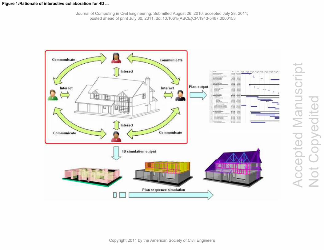
collaborative planning can lead to a synthesized plan and 4D simulation (Figure 1).
In order to realize this collaborative planning, inputting a 3D model (either entity-based or
BIM-based) can foster both social interaction and user-system interaction for effective teamwork. This
unified 3D model permits access to all planners such that they obtain their own building information,
namely PBS, through 3D navigation and direct manipulation. These operations include zoom in/out,
pan, rotate, decompose, and pick up/off, etc. in a 3D environment. Planners can thus define associated
tasks on related 3D elements, and further generate 4D simulation. In the interactive definition method,
a set of established parameters called simulation (SIMU) items can help planners define plan tasks and
related simulation on 3D elements. This method is thus named PBS-create-WBS (PBSWBS). Its
feasibility has been verified in a local area network (LAN) situation (Zhou et al. 2009), in which related
CSCW design in the method plays an irreplaceable role in the collaboration process.
4D CSCW Design
Greenberg (1991) stated that "CSCW is about how people work together, and how the
computer and related technologies affect group behavior." For the purpose of effectively supporting
geographically distributed planners for collaborative 4D planning, any related CSCW design ought to
facilitate the planners’ mental process, social interaction and task performance. It strives to make their
planning process open-ended, synchronous and communicated through teamwork. According to the
enumerated features of communication, configuration, coordination, information access, interaction,
and usability in CSCW design (Mills 2003), the interactive definition method involves a series of
collaborative teamwork sessions in its application processes. Individual planners hence can team up for
Journal of Computing in Civil Engineering. Submitted August 26, 2010; accepted July 28, 2011; posted ahead of print July 30, 2011. doi:10.1061/(ASCE)CP.1943-5487.0000153
Copyright 2011 by the American Society of Civil Engineers
Accep
ted M
anus
cript
Not Cop
yedit
ed
8
co-creating a robust plan across the Internet. These sessions are co-navigate, co-sort, co-plan, co-
simulate and co-talk (Zhou et al. 2009).
Co-navigate and co-sort sessions are dedicated to analyzing spatial structure of a 3D building
model. Planners can co-navigate and analyze the 3D model together via zoom, pan, rotate, and
decompose to identify suitable 3D elements for defining plan tasks. The co-sort session enables
planners to interactively pick out related PBS items together from the 3D model whilst the co-plan
allows them to define simulation items on the co-sorted 3D elements for concurrent planning. The
defined items are then broadcast to every online planner and synthesized to be a complete plan. In
conjunction with online planners, co-simulate can help detect potential conflicts in the generated plan
across the network. Involved online planners can check potential conflicts, not only in their own, but
also the overall plan during the co-simulate session. In order to maintain a live social interaction in
planning, the co-talk session is available for this purpose. Audio-video conferencing and text chatting
are applicable choices in the session.
These collaborative sessions have two types. One is a conditional session, which requires an
invitation-acceptance agreement among collaborators. Co-navigate, co-sort, and co-simulate belong to
this type. The conditional session has a specific lifecycle about creation, process, and termination. Its
creation is dependent on the session holder and potential session attendees. The session holder is an
online collaborator who creates a collaborative session by sending out an invitation. Other online
collaborators are potential session attendees. Once accepting an invitation from a session holder, they
become the session attendees and a live conditional session is then created for teamwork. During a live
session through the processes of co-navigate, co-sort or co-simulate, the involved attendees and the
session holder can collaborate together for planning work. The session holder plays a dominant role in
controlling the session’s progress. Both the session holder and the attendees can perform related
concurrent operations, which are synchronously reflected in their systems. A live session can be
terminated at any time by either the session holder or the session attendees. Another session type is an
unconditional session, which can be launched by any online collaborators at any situation. The co-talk
session is a kind of unconditional session for communication using text chatting. The characteristic of
the unconditional session is that online planners can conduct them freely and concurrently. It has no
Journal of Computing in Civil Engineering. Submitted August 26, 2010; accepted July 28, 2011; posted ahead of print July 30, 2011. doi:10.1061/(ASCE)CP.1943-5487.0000153
Copyright 2011 by the American Society of Civil Engineers
Accep
ted M
anus
cript
Not Cop
yedit
ed
9
specific lifecycle about creation and termination when applying it. The co-plan session can be either
conditional or unconditional session depending on collaborators’ needs.
Conditional and unconditional sessions have different features. The conditional session is
close-ended that its collaborators are unable to join in another live conditional session at the same time.
A live conditional session has no influence on other sessions and on non-invited collaborators, who
also have no permission to join a created live session. Some synchronous operations and controlled
data of the session, e.g. zoom, pan, rotate etc. are limited within the session holder and the attendees.
The unconditional session, on the other hand, is open-ended that online planners can collaborate with
each other whether they are in a session or not. In other words, once planners are connected with the
network, they can perform unconditional sessions of text chatting and co-plan without constraints. It is
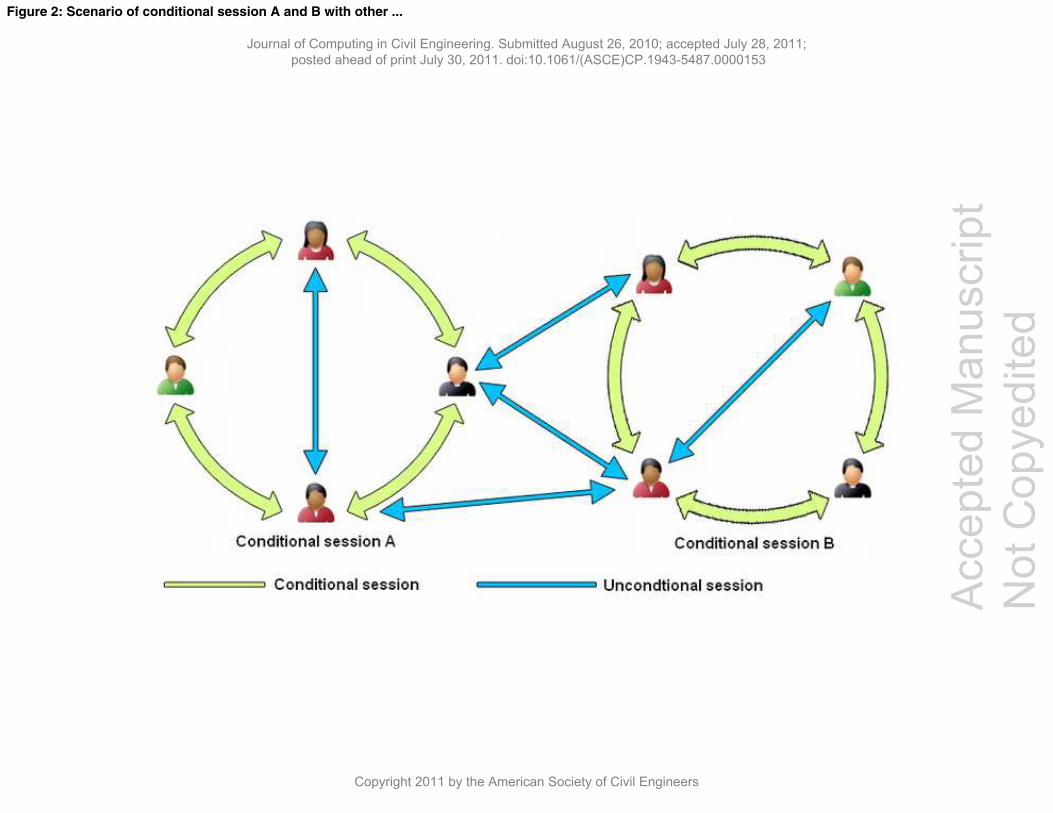
possible that several conditional sessions co-exist during planning. In such a scenario, an unconditional
session is a bridge to connect those parallel sessions and non-session planners for information exchange
(Figure 2). These features provide planners with flexible choices in collaboration. Depending on
specific planning situations, planners can choose related partners to create suitable conditional sessions
for focus group collaboration. Thus the whole collaborative teamwork in planning can be organized
dynamically and effectively.
Proposed Solution
In the light of foregoing discussion on 4D interactive collaboration and related CSCW design,
the distributed 4D groupware ought to offer certain functionalities to underpin related social-technical
activities to achieve collaborative planning. These functionalities are helpful to clarify the groupware
solution from three aspects: software architecture, application mode and data flow, as well as data
exchange protocol. The software architecture includes the main functional modules and components of
the system to support collaborative activities. It also decides its application mode and data flow when
performing those activities. In the meantime, stipulating a set of data exchange protocols is necessary
for realizing effective data transmission in real time. In view of the current dominant situation of entity-
based 3D CAD model in the industry (Tse et al. 2005), the proposed 4D groupware targets non-BIM
based 3D models to discuss its development in a more generic condition.
Journal of Computing in Civil Engineering. Submitted August 26, 2010; accepted July 28, 2011; posted ahead of print July 30, 2011. doi:10.1061/(ASCE)CP.1943-5487.0000153
Copyright 2011 by the American Society of Civil Engineers
Accep
ted M
anus
cript
Not Cop
yedit
ed
10
Software Architecture
The proposed software architecture consists of a client tier and a server tier (Figure 3). These
two tiers own the modules of 4D builder and 4D item pool respectively. Both tiers also contain a
module of communication services with related management components. Among these modules, the
4D builder in the client tier includes two components of 3D element container and SIMU item
container. They can provide PBS information for simulation item generation and restoration. The 4D
builder also involves three components including file management, plan browser and 4D player for
those containers’ management and utilization. In the server tier, the 4D item pool module owns three
components of 3D element container, SIMU item synthesizer, and role-attribute reactor to provide
collaborative information to the client tier. It links several components of browsers and file
management. These four fundamental modules are all connected with an event hub module in two tiers
for data transmission.
Event Hub
The event hub module, being included in both the server tier and client tier, takes
responsibility for exchanging data between two tiers. It has an event-based mechanism for identifying,
sending, and receiving information to ensure effective data exchange. In order to achieve this aim, the
event hub contains a set of components including event enumerator, event identifier, data carrier, and
exchange centre (Figure. 4). The event enumerator defines a series of system events, which can deal
with any data operations and updates from both system and users. They help describe specific requests
for data sending or receiving internally and externally, and then choose corresponding operations. The
event identifier functions by getting an incoming event internally or externally, and interprets it
according to event definition by the event enumerator. As a result, the data carrier is triggered to
choose a suitable data buffer for loading the coming data. These data then are passed to either the
exchange centre for external transferring or internal components directly. Both event hubs in the client
tier and server tier adopt the same event-based mechanism. The only difference lies in their converse
operations for data exchange, e.g. an event can result in sending operation in the client tier whilst the
same event can lead to receiving operation in the server tier.
Journal of Computing in Civil Engineering. Submitted August 26, 2010; accepted July 28, 2011; posted ahead of print July 30, 2011. doi:10.1061/(ASCE)CP.1943-5487.0000153
Copyright 2011 by the American Society of Civil Engineers
Accep
ted M
anus
cript
Not Cop
yedit
ed
11
Communication Services
Both the client and server tiers contain a communication services module. In the server tier,
the module has the component of role services to provide definition of specialty role for collaborators.
Considering collaborative planning from multidisciplinary planners, collaborators need to explicitly
decide their expertise in the planning process. The role services component in the server tier can record
collaborators’ role choices and their states in collaborative processes. The role definition is managed by
the communication management component, which allows input/output or directly edit operation to
manage specialty roles. Besides these role services, the communication services module is also in
charge of server start or stop as well as data dispatching among collaborators. Underpinned by the
event hub, the communication services module can identify upcoming events’ sources and destinations,
and thus dispatch carried data to the relevant collaborators.
In the client tier, the communication services module consists of the components of the role
register and the messenger. According to the user’s specialty, the role register component enables
collaborators to select a state and a role provided from the role services component in the server tier. It
is also used for recording and displaying other collaborators’ states. On the other hand, the messenger
can support collaborators’ communication through text chatting. By receiving data from the server tier,
the messenger displays incoming texts to local planners. It also ensures collaborators input text and
send to targeted online planners via the server. Additionally, the conference centre component can host
other advanced built-in components for audio-video conferencing if needed. Besides this option,
commercially available audio and videoconferencing services are applicable for concurrent engineering
as they can directly contribute value to team efforts (Pena-Mora 2000).
4D Builder
The 4D builder module in the client tier can synthesize simulation items with 3D model
elements. Its SIMU item container component contains a series of text-based task items to record
defined WBS items and their associated PBS elements. Another component of the 3D element
Journal of Computing in Civil Engineering. Submitted August 26, 2010; accepted July 28, 2011; posted ahead of print July 30, 2011. doi:10.1061/(ASCE)CP.1943-5487.0000153
Copyright 2011 by the American Society of Civil Engineers
Accep
ted M
anus
cript
Not Cop
yedit
ed
12
container possesses a series of 3D graphical elements to represent inputted PBS. Because a simulation
item wraps PBS elements with WBS item together, the SIMU item container and the 3D element
container are interrelated with each other. Every item in the SIMU item container can refer to its related
3D elements in the 3D element container, and vice versa. In the offline condition, these two containers
can be managed by their file systems to input and/or output 3D model files and simulation item files
respectively. In the online condition, the containers can be filled in through retrieving data from the 4D
item pool in the server tier. Additionally, both of them in the client tier have a browser to view their
contents. The browser of the 3D element container is also a 4D player. It can not only assist 3D model
analyzing and viewing, but also present 4D simulation when defined simulation items are synthesized.
The browser of the SIMU item container can help view defined simulation items and hierarchal plan
structure, which is generated by a plan editor. The planner can define simulation items via this editor
by inputting appropriate values
4D Item Pool
The 4D item pool module in the server tier has three components of 3D element container,
role-attribute reactor, and SIMU item synthesizer. As a central data repository, these three components
in this module can supply the client tier with unique 3D elements and their attributes, as well as
synthesized simulation items. All of them provide content management through their own file systems,
and each of them owns a browser for checking its content.
The applicable 3D model for this module adopts Autodesk .3DS and Microsoft .X formats. A
simple 3D model browser can be used for checking a loaded 3D model in the 3D element container. It
displays an overall 3D model profile for the administrator’s management. Specific spatial information
of the loaded 3D elements is unnecessary to show in the server tier. Nevertheless, their names need to
be listed in the role-attribute browser to build correspondence between defined specialty roles and the
3D elements. This correspondence will help decide each 3D element’s attribute for every defined role.
The planners can thus perform simulation item definition according to generated 3D elements’
attributes. The SIMU item synthesizer is applied for integrating defined simulation items from different
planners. According to every defined item’s specification and overall plan situations, the synthesizer
Journal of Computing in Civil Engineering. Submitted August 26, 2010; accepted July 28, 2011; posted ahead of print July 30, 2011. doi:10.1061/(ASCE)CP.1943-5487.0000153
Copyright 2011 by the American Society of Civil Engineers
Accep
ted M
anus
cript
Not Cop
yedit
ed
13
will assign each item with a unique order to generate an integrated plan. Its browser can be applied for
viewing the generated hierarchal plan.
The role-attribute reactor takes the responsibility of generating 3D elements’ attributes – the
PBS elements’ attributes for each collaborator. It also deals with PBS read/write access control. As
collaborators focus on their own PBS elements for task definition, the reactor can thus lead to such a
result that only writable PBS elements of a collaborator can be defined with tasks. It means that
collaborators ought to decide PBS elements’ read-write privilege beforehand so as to suit their planning
specialties. Such a mechanism was described as user’s perspective in the research of distributed virtual
engineering (DVE) (Maxfield 1998). It applied an information mask, namely filter, to get meaningful
information for different clients. A similar concept can be applicable for model-based collaborative 4D
planning to identify planners’ interested information. In case an inputted 3D model owns building
information, e.g. BIM model, its PBS items’ read-write privilege for collaborators can be decided
simply according to its internal differentiation. However, an inputted 3D model without building
information requires a mechanism to identify PBS, and then decide its privilege for collaborators. In
the proposed groupware, visual identification is a feasible way to realize this aim. Given a 3D element
without building information, the role-attribute reactor ought to consider four possible visual
identification results for attribute generation: Free (F), Readable (R), Writable (W), and Conflict (C). A
specific element attribute value is dependent on all collaborators’ selection results. This interrelated
situation is illustrated in Table 1.
Situation 1 in Table 1 shows a PBS element is of free attribute for all collaborators. It can be
selected by the collaborators to set the writable attribute if the element belongs to their domains. Once a
PBS element – a 3D element is set with the writable attribute by only one collaborator e.g. collaborator
A, then this element’s attribute becomes readable for other collaborators. This condition is
corresponding to the situation 2 in the table. In case a writable element is further picked out by another
or more collaborators, this element then is in a conflict state. Its attribute is a conflict for those co-
owners but not other collaborators who do not select the element. It still has a readable attribute for
them. This condition is corresponding to the situation 3 in the table. Given an element with the conflict
attribute, co-owners could give up their selections so that the element can be of either writable attribute
Journal of Computing in Civil Engineering. Submitted August 26, 2010; accepted July 28, 2011; posted ahead of print July 30, 2011. doi:10.1061/(ASCE)CP.1943-5487.0000153
Copyright 2011 by the American Society of Civil Engineers
Accep
ted M
anus
cript
Not Cop
yedit
ed
14
for only one owner, or free attribute for all collaborators. This role-attribute reaction mechanism can
dynamically generate a PBS element’s attribute for every collaborator depending on all collaborators’
selections. Its specific attribute is different from role to role. The administrator can monitor this
assignment through the role-attribute browser.
Application Mode and Dataflow
The proposed distributed software architecture is based on the server/client paradigm. The
server is a central data repository connecting with a series of clients (Figure 5). The connection
between the server and the clients can be through the Internet or LAN depending on collaborative
requirements. In view of adopting the file management system in the server side, one of clients,
possibly the main contractor, needs to be located in the same place with the server. Besides a planner’s
role in collaborative planning, the user of this client ought to play an administrator’s role in
maintaining the server’s normal working.
The shared repository structure of the server/client mode implies that any collaborative work
among clients needs the server’s link. Involved data transmission between the server and the clients
follows three approaches of updated broadcast, direct transfer, and automatic retrieve (Figure 6). The
updated broadcast and the direct transfer follow several procedures. Firstly, an operation is performed
via a user interface of 4D builder or communication services in client A. The conducted operation then
carries some data from the 4D builder or communication services to the event hub. Secondly, it triggers
its registered event to be dealt with by the event hub, and delivers the event and data via the network to
the event hub of the server side. Afterwards, the server side can parse the transferred event and choose
corresponding operations. These operations result in either updated broadcast or direct transfer to client
B. The former causes data updating in the 4D item pool and broadcast to all clients whilst the latter
causes data to be dispatched directly to target clients. Additionally, the automatic retrieve simply
occurs when a client connects the server to get information from the 4D item pool. Its data flow is
partly the same with that of the updated broadcast. The difference is that retrieved data are only
transferred to the requested client but not to be broadcasted to other clients.
Journal of Computing in Civil Engineering. Submitted August 26, 2010; accepted July 28, 2011; posted ahead of print July 30, 2011. doi:10.1061/(ASCE)CP.1943-5487.0000153
Copyright 2011 by the American Society of Civil Engineers
Accep
ted M
anus
cript
Not Cop
yedit
ed
15
Real-Time Data Exchange Protocol
Given three data transfer approaches between the server and the client, establishing a set of
protocols can help the system choose suitable approaches to effective data exchange in real time. These
protocols decide transferred data to follow right approaches and reach correct destinations. The
protocols include automatic data flood and controlled data transfer. The former further consists of static
data flood protocol and dynamic data flood protocol.
The static data flood protocol has an effect on retrieving existing data directly from the 4D
item pool of the server to the clients. Existing data, including the PBS elements, their attributes, defined
roles, and generated simulation items, are usually recorded and stored in the server side. When the user
connects the server to log in, these data will be automatically retrieved from the server to the client.
This static data transfer protocol enables users to obtain existing data from the server following the
automatic retrieve approach. Its transfer direction is singular from the server to the clients.
The dynamic data flood protocol, on the other hand, follows the approach of the updated
broadcast in order to transfer new generated information to the server for restore and synthesis, and
further to broadcast to all online clients. This protocol takes effect during the user’s log in/off the server.
When logging in the server, the user needs to input a user name, select a role and a working state. This
new information is sent to and recorded in the server, and broadcasted to other online users. Similarly,
when a user logs off the server, other online users are informed instantly. During collaboration periods,
moreover, newly updated PBS attributes and defined simulation items by a client also apply this
protocol to broadcast them to all clients. Its transfer direction is multiple for all online clients. Both
static and dynamic data transfer protocols maintain a unified real-time environment whenever
collaborators join in, leave, and participate in collaborative work.
The controlled data transfer protocol works in the collaborative sessions of co-navigate, co-
talk, and co-simulate. A significant feature of this protocol is that exchanged data are assisting
information without the needs of restore and display in the server. A session holder can control the
session’s creation, termination, process, and contents whilst session attendees are passive to receive
Journal of Computing in Civil Engineering. Submitted August 26, 2010; accepted July 28, 2011; posted ahead of print July 30, 2011. doi:10.1061/(ASCE)CP.1943-5487.0000153
Copyright 2011 by the American Society of Civil Engineers
Accep
ted M
anus
cript
Not Cop
yedit
ed
16
these data. It has no influence on other online collaborators who are out of the session. Its data flow
adopts the approach of direct transfer from the session holder to the session attendees. Therefore, its
data transfer direction is limited within several related clients only.
Nevertheless, the controlled data transfer protocol is usually overlapped with the automatic
data flood protocol in the collaborative sessions of co-sort and co-plan. In view of overhead data such
as simulation items and PBS attributes generated in these sessions, the automatic data flood protocol is
applicable to broadcast these data to all online collaborators no matter they are in or out of
collaborative sessions.
Implemented Prototype
In accordance with the rationale of the proposed solution, a prototype named 4DX was
implemented at the University of Wolverhampton in the UK. Its development toolkits are Microsoft
Visual C++ 8.0 (Visual Studio 2005), Direct3D 9.0, and Winsock 2.0. They are popular utilities for the
Windows platform to create networked real-time 3D graphical applications, and compatible with most
hardware. The object-oriented programming (OOP) approach is applied for the system development.
The prototype consists of a server side application and a client side application running in the network
condition. Its underlying communication is based on the TCP/IP protocol. The implementation results
are presented as follows.
Server Side Application
The server side application constructs the server tier’s modules of event hub, communication
services, and 4D item pool. It integrates necessary collaborative planning information in the 4D item
pool for retrieving and updating from client sides. This collaborative planning information includes 3D
elements and their attributes, simulation items, as well as specialty roles. The management of this
information is performed through separate file systems of the components of 3D element container,
role-attribute reactor, SIMU item synthesizer, and role editor respectively. Each of these components
provides a browser integrated in the user interface for content checking and managing (Figure 7).
Journal of Computing in Civil Engineering. Submitted August 26, 2010; accepted July 28, 2011; posted ahead of print July 30, 2011. doi:10.1061/(ASCE)CP.1943-5487.0000153
Copyright 2011 by the American Society of Civil Engineers
Accep
ted M
anus
cript
Not Cop
yedit
ed
17
A thumbnail 3D model browser is dedicated to the 3D element container. It provides basic 3D
navigation operations such as zoom, pan, and rotate for simply browsing a loaded 3D model. 3D
elements’ names are displayed in the browser of the role-attribute reactor when a 3D model is loaded in
the server. The role-attribute browser can combine defined specialty roles to show the attribute of each
3D element while collaborators decide PBS items’ read-write privileges in their clients. The definition
of specialty role is through the role editor. Each defined role with its user name and working state is
displayed in the role browser. Moreover, the browser of the SIMU item synthesizer displays a
synthesized result of simulation items in a text-based hierarchal structure. Additionally, the
communication services component ensures the server communicate with its external clients. The
administrator in the server side needs to specify an unoccupied communication port for data exchange
with the clients. Once the server is started, system states such as server start /stop, and collaborator’s
log in/off etc. are reported in an event window. Based on these transparent features, the administrator
can effectively manage the server and monitor its working situations.
Client Side Application
The client side application builds the client tier modules of 4D builder, communication
services, and event hub. It enables multidisciplinary planners to conduct planning work in their local
systems while communicating and collaborating with each other. Among these modules, the 4D builder
supports planning activities including 3D model analysis, simulation item definition, as well as 4D
sequence generation. The communication services module allows planners to communicate with
remote collaborators, such as server connection, role registration, text charting etc. The event hub
module at a low level undertakes all data transmission to underpin high-level operations from planners.
The client side application integrates the user interfaces of all the modules’ components
(Figure 8). A communication panel is prepared for the user to connect the server, select a predefined
specialty role, and list all online collaborators and their states. An instant messenger is also available
for the planner to communicate with other online collaborators. A 3D-based planning environment is
created as the 4D player for 3D model browsing and analyzing, 3D elements picking, simulation item
Journal of Computing in Civil Engineering. Submitted August 26, 2010; accepted July 28, 2011; posted ahead of print July 30, 2011. doi:10.1061/(ASCE)CP.1943-5487.0000153
Copyright 2011 by the American Society of Civil Engineers
Accep
ted M
anus
cript
Not Cop
yedit
ed
18
defining, and 4D simulation player. The loaded 3D model and plan from a local system can fill in the
3D element container and the SIMU item container. They are displayed in the 4D player and the plan
browser respectively. The same result can be achieved by retrieving data from the 4D item pool in the
server side when planners log in the server.
Applying the 4DX client application for creating a plan, planners can navigate and analyze the
3D model in the 4D player via zoon, pan, and rotate operations. In view of the overlapped nature of 3D
elements in the model, a topology displaying control is devised to help planners decompose the 3D
model. It is able to control the 3D model’s elements, displaying one by one in a bottom-up or top-down
order. Planners thus have the opportunity to scrutinize every 3D element of the model. On deciding a
task definition, planners can pick up related 3D elements to specify the task via the SIMU item
definition panel. The defined task is then synthesized with picked 3D elements to be a simulation item.
The newly created simulation item is automatically sent to the server for integration with other defined
simulation items, and then received and recorded in the local SIMU item container. With created
simulation items, the 4D player is thus able to detect potential conflicts in the plan by 4D simulation.
Leveraging the network support, all these planning activities can be conducted across the network by
the collaborative sessions of co-navigate, co-sort, co-plan, co-simulate, and co-talk. Therefore,
planners’ work is open-ended, communicated, and it is possible to achieve a robust plan.
Through a user-centered design, the user interface/interaction (UI) design of the 4DX client is
further adapted to be collaboration oriented (Figure 9). In this circumstance, some graphical user
interfaces (GUIs), such as the instant messenger and logging panel, are removed or hidden. The
planners hence can focus on the main planning tasks independently or collaboratively depending on
whether or not they involve online collaborators. In case of no other online planners selected or
available, the planner can perform planning individually through the operations of navigate, sort, plan
and simulate. In case of selecting online planners, these operations become available in the
collaborative sessions of co-navigate, co-sort, co-plan and co-simulate. This flexibility enables 4DX
client to be applicable for both offline and online conditions.
Journal of Computing in Civil Engineering. Submitted August 26, 2010; accepted July 28, 2011; posted ahead of print July 30, 2011. doi:10.1061/(ASCE)CP.1943-5487.0000153
Copyright 2011 by the American Society of Civil Engineers
Accep
ted M
anus
cript
Not Cop
yedit
ed
19
System Validation
The system validation was performed in a truly geographically distributed condition. Four
planners were involved to apply 4DX clients in different locations to collaborate with each other
simultaneously across the Internet. A commercially available multiparty video conferencing system
named ooVoo was leveraged to bridge the gap among these geographically dispersed planners, who
could communicate with each other face-to-face in real time during the planning process. The
validation applied several multimedia PCs with dual monitors and connections to the Internet. The
dual-monitor setting was dedicated to displaying both 4DX and ooVoo in one client. A prepared entity-
based 3D building model (Figure 9) was adopted in the validation. According to the availability of
building elements in the 3D model, four roles were correspondingly defined as structure planner,
window planner, door planner, and glass planner in the server side. During the testing process, the team
members located in different buildings within the University of Wolverhampton, which provided
unlimited wireless Internet access for all users.
Process and Result
The overall validation process followed a serial workflow of co-sort and co-plan. In the co-
sort session, team members engaged in sorting building information concurrently to customize their
specialty-oriented planning context. Subsequently, the team members performed concurrent planning in
their own contexts. During these two procedures, co-navigate was utilized to help the plan team
analyze the 3D model while co-talk provided communication services using the ooVoo throughout the
whole process. Co-simulate contributed to the co-plan when the plan team wanted to detect potential
conflicts during the planning. Both co-navigate and co-simulate were used by the team for concurrent
individual work in client sides and collaborative teamwork across the Internet.
When starting the validation planning, all team members signed in the ooVoo first. The server
administrator started the 4DX server, and sent the server IP address as well as a communication port to
other collaborators via the ooVoo. All the team members then logged in the server and retrieved the 3D
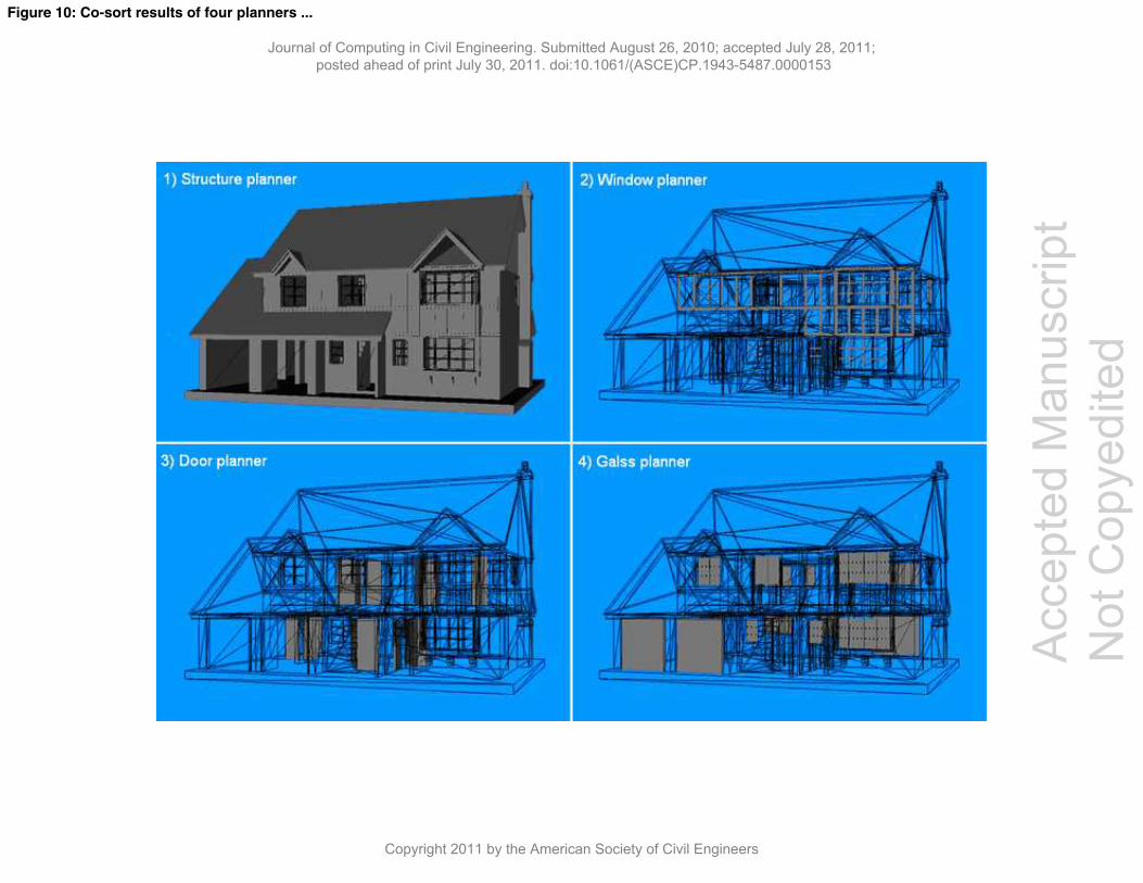
model from the server to their local systems. The control tester initiated the co-sort so that all
Journal of Computing in Civil Engineering. Submitted August 26, 2010; accepted July 28, 2011; posted ahead of print July 30, 2011. doi:10.1061/(ASCE)CP.1943-5487.0000153
Copyright 2011 by the American Society of Civil Engineers
Accep
ted M
anus
cript
Not Cop
yedit
ed
20
collaborators could pick up their 3D elements from the 3D building model. A set of filters for
controlling 3D element display state was designed in the UI so that collaborators could use them to
filter out relevant 3D building information and obtain their own PBS elements. Taking the advantages
of created building information visualization by the system as well as real-time multiparty video
conferencing from ooVoo, all planners successfully sort their own 3D elements collaboratively and
concurrently across the Internet. Its result is illustrated in Figure 10. As indicated in the illustration, the
3D elements with black mesh in the model are readable whilst the 3D elements in the grey solid state
are writable for defining simulation items.
After obtaining their own 3D building elements, the collaborators proceeded to the co-plan to
conduct planning together. They focused on their own 3D elements to define simulation items. During
this procedure, the collaborators still maintained social interaction via ooVoo to exchange planning
strategy, adjust their own definition, and give suggestions to other collaborators simultaneously. As
they shared the same plan context, updates by any collaborator were reflected on the client machines of
other users via server broadcasting in real time. Co-simulate was also conducted in the co-plan process
across the Internet so that to identify and eliminate potential conflicts in the co-created plan. A robust
plan therefore could be guaranteed under the monitoring from collaborators. The screen shot of this co-
plan working is illustrated in Figure 11.
The final construction plan that was generated was shown in a hierarchal structure, and could
be exported into MS Project to gain the same structured plan with a bar chart (Figure 12). This result
kept consistency with that of the verification test. Its complete 4D simulation sequence is presented in
Figure 13. These results indicate the effectiveness of the proposed 4D groupware, and further verify the
applicability of the interactive definition method. Combining the commercial multiparty video
conferencing system of ooVoo, the proposed 4D groupware solution is feasible for geographically
dispersed planners to collaboratively conduct planning and simulation across the Internet.
Journal of Computing in Civil Engineering. Submitted August 26, 2010; accepted July 28, 2011; posted ahead of print July 30, 2011. doi:10.1061/(ASCE)CP.1943-5487.0000153
Copyright 2011 by the American Society of Civil Engineers
Accep
ted M
anus
cript
Not Cop
yedit
ed
21
Findings in Validation
The validation confirms that the proposed 4D groupware solution is applicable for distributed
collaborative planning through teamwork. Applying the server-client mode, geographically dispersed
planners can collaborate with each other from their own clients connected by the server. The devised
functional modules effectively supported multidisciplinary planners’ CSCW sessions across the
Internet. They interactively held collaborative sessions during their concurrent planning. This suggests
that the underlying real-time data exchange protocols and data flow in the CSCW design were
successful to underpin diverse data transmission for team-based collaborative planning. The design of
the 4D item pool in the server side demonstrated feasibility and flexibleness to use a file-based
structure to supply the clients with collaborative information. Particularly, the mechanism of role-
attribute reactor enables multidisciplinary planners to perform interactive collaboration targeting a
unique 3D model even without building information. This feature brings convenience for collaborators
to filter out their interested building components which may not belong to BIM.
The use of 3D BIM model will be an important compensation for the proposed solution. The
proposed solution aims at a 3D CAD model condition because the entity based 3D CAD model is still
prevalent in the construction industry. Since the entity-based 3D CAD model has no building
information, a 4D item pool (acting as a central building information repository) is populated by
applying several separate files, which supply necessary information for planning. Such a loose
information management is flexible to customize collaborative information for different situations.
Nevertheless, it increases management burden in the server. A BIM-based file structure such as
Industry Foundation Classes (IFC) for the 4D item pool is possible to integrate all parts into a complete
information repository. The benefit of adopting BIM into the system lies not only in simplifying the
server management, but also possibly automating PBS filter out rather than interactive co-sort in the
client side. As BIM-based file has already owned classified building information, collaborators could
directly obtain desired PBS information from the server. However, it is reasonable to believe that 3D
CAD model and BIM model will always co-exist in the AEC industry. In some circumstances, 3D
CAD models are useful to simply represent some temporary elements, e.g. formwork or scaffolding,
Journal of Computing in Civil Engineering. Submitted August 26, 2010; accepted July 28, 2011; posted ahead of print July 30, 2011. doi:10.1061/(ASCE)CP.1943-5487.0000153
Copyright 2011 by the American Society of Civil Engineers
Accep
ted M
anus
cript
Not Cop
yedit
ed
22
which may not necessarily use BIM. Combining interactive co-sort with automated filtering can be
effective and convenient for users to deal with both situations of 3D CAD and BIM models.
The concurrency feature of the prototype needs to be reinforced. A requirement for the
collaborators in the validation is that their defined plan tasks comply with an ideal top-down order
according to their start time. It needs the planners to define their tasks one by one according to the real
temporal and logical construction sequences. This collaborative planning strategy is positive to gain a
robust plan and helpful to expose and identify potential conflicts in the 4D simulation. It can also be
applicable for real project practice. However, planners are able to define their plan tasks freely and
concurrently once obtaining their own 3D elements in normal situations. This freedom and concurrency
may cause some earlier tasks to be defined later because of time difference in concurrent work. The 4D
simulation of this study excludes this possibility for the purpose of controlling the validation
experiment. In a real situation, this exclusion can cause later defined tasks with early start time to be
neglected in the simulation. In order to satisfy the concurrent operation’s need, the implemented 4D
simulation generation mechanism needs modification to become fully time oriented. The remedy of this
pitfall would be positive for this groupware to suit concurrent planning situation.
The dual-monitor configuration for the prototype provided convenience in the validation.
Because of using multiple applications of the 4DX and the ooVoo at the same time, a clear and ease-of-
use arrangement for the system is important to achieve good usability. Real-time collaborative 4D
planning has high demands for user tasks’ performance including 3D operation, interactive definition,
and social interaction. These mixed user tasks ask for suitable operation schemes to support user’s task
performance. Dual-monitor configuration permits users to easily conduct main task operations instead
of frequently switching user interfaces among different applications. It thus can be helpful to improve
the usability of the whole system. Interestingly, it is an attractive topic regarding the interaction design
for the promotion of user performance in the condition of multiple monitors and applications. Some
research efforts have been invested into this human factor field. It is anticipated combing related
achievements with current distributed 4D groupware for further study.
Journal of Computing in Civil Engineering. Submitted August 26, 2010; accepted July 28, 2011; posted ahead of print July 30, 2011. doi:10.1061/(ASCE)CP.1943-5487.0000153
Copyright 2011 by the American Society of Civil Engineers
Accep
ted M
anus
cript
Not Cop
yedit
ed
23
Finally the validation further verifies the applicability of the interactive definition method for
collaborative 4D planning in a truly geographically distributed condition. The validation result shows
that geographically dispersed multidisciplinary planners are able to co-create a robust plan via the team
worked social interaction, user-system interaction, and plan data incorporation in an open shared
social-technical context. The use of 3D model for creating the social-technical context is positive to
foster collaborative planning and caters for the planner’s mental process. Within this context, the
planners are motivated to ponder planning strategies, exchange information with collaborators, and
formulate solutions to define simulation items. Meanwhile, the application of commercially available
tool of ooVoo is helpful to achieve social interaction. As the interactive definition method permits the
planners to gain external information inputs from collaborators during planning, its 4D planning
process hence features open-ended, communicated, and collaborative characteristics. Additionally, the
co-created construction plan and generated 4D simulation in the validation is evidence that the use of
simulation item parameters provided by the method is effective to define 4D construction plan. They
show convenience and efficiency for network transmission, plan synthesis, and simulation generation.
Conclusion and Future Work
This paper proposed a model-based groupware solution that was validated to be effective for
distributed real time collaboration. Its collaborative mechanisms, including software architecture,
application mode and data flow, as well as data exchange protocol, are applicable for synchronous
model-based teamwork environments. Applying the proposed 4D groupware, multidisciplinary
planners can effectively perform collaborative planning across the boundaries of time, location and
specialty. The applicability of collaborative mechanisms in the proposed groupware can be useful for
equivalent applications in the AEC industry and other industries. Given the social-technical context for
collaborative planning, paying attention to only technical aspects such as data integration and
interoperability is constructive in groupware development but insufficient to guarantee collaborative
teamwork when applying it. This study takes both social and technical issues into account to explore a
successful 4D groupware development. Although its validation was performed in a simulated
construction project, it still highlighted essential issues of applying the 4D groupware in a distributed
condition. The validation also revealed the need for future functionality that will enhance CSCW
Journal of Computing in Civil Engineering. Submitted August 26, 2010; accepted July 28, 2011; posted ahead of print July 30, 2011. doi:10.1061/(ASCE)CP.1943-5487.0000153
Copyright 2011 by the American Society of Civil Engineers
Accep
ted M
anus
cript
Not Cop
yedit
ed
24
design, social coordination, awareness, and user interface/interaction design. The discussion of these
sort of issues is out of the scope of this paper, and be expected a further clarification in another report.
The demonstrated benefits and exposed weaknesses in the current solution will be positive to nurture
more practical 4D groupware solutions. It is meaningful to turn construction planning from a
multidisciplinary activity to be an interdisciplinary practice. Its industry project validation will further
verify its effectiveness, advancement and disclose potential pitfalls. More insights about applying the
model-based groupware for distributed collaborative teamwork are expected to be gained in the future.
References
Autodesk (2010). Revit architecture 2011 user's guide, Autodesk, Inc. April 2010.
Bentley (2011). Dynamic collaboration for iterative project review, Bentley Systems, Inc. Accessible
Collier, E. and Fischer, M. (1996). Visual-based scheduling: 4D modelling on the San Mateo County
Health Centre, Proceedings of the 3rd ASCE Congress on Computing in Civil Engineering, Anaheim,
CA.
Dawood, N., Scott, D., Sriprasert, E., and Mallasi, Z. (2005). The virtual construction site (VIRCON)
tools: An industrial evaluation, ITcon Vol. 10, Special Issue From 3D to nD modelling , pg. 43-54,
http://www.itcon.org/2005/5
Fischer,G., Giaccardi, E., Eden, H., Sugimoto, M., Ye, Y. (2005). Beyond binary choices: Integrating
individual and social creativity, International Journal of Human-Computer Studies, Volume 63, Issues
4-5, October 2005, Pages 482-512
Frohlich, B., Fischer, M., Agrawala, M., Beers, A., and Hanrahan, P. (1997). Collaborative production
modelling and planning. IEEE Computer Graphics and Applications, 17(4), 13–15.
Journal of Computing in Civil Engineering. Submitted August 26, 2010; accepted July 28, 2011; posted ahead of print July 30, 2011. doi:10.1061/(ASCE)CP.1943-5487.0000153
Copyright 2011 by the American Society of Civil Engineers
Accep
ted M
anus
cript
Not Cop
yedit
ed
25
Fruchter, R. (1999). Architecture/Engineering/Construction Teamwork: A Collaborative Design and
Learning Space, Journal of Computing in Civil Engineering, October 1999, Vol 13 No.4, pp 261-270.
Garner, S. and Mann, P. (2003). Interdisciplinarity: perceptions of the value of computer-supported
collaborative work in design for the built environment, Automation in Construction, Volume 12, Issue
5, September 2003, Pages 495-499
Gtwiki (2009). SVN Client setup, gtwiki, March 2009. Accessible online:
Grudin, J. (1994). Groupware and social dynamics: eight challenges for developers, Communications
of the ACM archive, Volume 37, Issue 1 (January 1994), pp92 - 105, 1994, ISSN: 0001-0782
Heesom, D. and Mahdjoubi, L. (2004). Trends of 4D CAD applications for construction planning,
Construction Management & Economics, 22, 171-182. 2004.
Journal of Computing in Civil Engineering. Submitted August 26, 2010; accepted July 28, 2011; posted ahead of print July 30, 2011. doi:10.1061/(ASCE)CP.1943-5487.0000153
Copyright 2011 by the American Society of Civil Engineers
Accep
ted M
anus
cript
Not Cop
yedit
ed
26
Hendrickson, C. (1998). Project Management for Construction, Department of Civil and Environmental
Engineering, Carnegie Mellon University, Pittsburgh, PA l52l3. Available from:
http://www.ce.cmu.edu/pmbook/
Jongeling, R. and Olofsson, T. (2006). A method for planning of work-flow by combined use of
location-based scheduling and 4D CAD , Automation in Construction, In Press, Corrected Proof,
Available online 24 May.
Kang, J., H., Anderson, S., D., and Clayton, M., J. (2007). Empirical Study on the Merit of Web-Based
4D Visualization in Collaborative Construction Planning and Scheduling, Journal of Construction
Engineering and Management. Volume 133, Issue 6, pp. 447-461, 2007
Khanzode, A., Fischer, M., Reed, D. (2008). Benefits and lessons learned of implementing building
virtual design and construction (VDC) technologies for coordination of mechanical, electrical, and
plumbing (MEP) systems on a large healthcare project, ITcon Vol. 13, Special Issue Case studies of
Koo, B. and Fischer, M. (2000). Feasibility Study of 4D CAD in Commercial Construction, Journal of
Construction Engineering and Management Jul/Aug
Ku. K., Pollalis, S., Fischer, M., Shelden, D. (2008). 3D model-based collaboration in design
development and construction of complex shaped buildings, ITcon Vol. 13, Special Issue Case studies
of BIM use, pg. 258-285, http://www.itcon.org/2008/19
Li, H., Ma, Z., Shen, Q., Kong, S. (2003). Virtual experiment of innovative construction operations.
Automation in Construction, 12(5): 561-575.
Journal of Computing in Civil Engineering. Submitted August 26, 2010; accepted July 28, 2011; posted ahead of print July 30, 2011. doi:10.1061/(ASCE)CP.1943-5487.0000153
Copyright 2011 by the American Society of Civil Engineers
Accep
ted M
anus
cript
Not Cop
yedit
ed
27
Manning, R., Messner, J. (2008). Case studies in BIM implementation for programming of healthcare
facilities, ITcon Vol. 13, Special Issue Case studies of BIM use, pg. 246-257,
http://www.itcon.org/2008/18
Maxfield, J., Fernando T., Dew P.M., (1998). Synchronous collaboration through a distributed virtual
environment in concurrent engineering, presence: teleoperators and virtual environments, pages 241 –
261, Vol.7, Issue 3.
Mills, K., L. (2003). Computer-Supported Cooperative Work. Encyclopedia of Library and Information
Pazlar, T., Turk, Z. (2008). Interoperability in practice: geometric data exchance using the IFC
standard, ITcon Vol. 13, Special Issue Case studies of BIM use , pg. 362-380,
http://www.itcon.org/2008/24
Pena-Mora, F., Hussein, K., Vadhavkar, S., Benjamin, K. (2000). CAIRO: a concurrent engineering
meeting environment for virtual design teams, Artificial Intelligence in Engineering 14 (2000) 203-219
Shelbourn, M., Bouchlaghem, N.M., Anumba, C. and Carrillo, P. (2007). Planning and implementation
of effective collaboration in construction projects, Construction Innovation, Vol. 7 No. 4, 2007, pp.
357-377.
Sriprasert, E. and Dawood, N. (2003). Multi-constraint information management and visualisation for
collaborative planning and control in construction, ITcon Vol. 8, Special Issue eWork and eBusiness ,
pg. 341-366, http://www.itcon.org/2003/25
Sulankivi, K., Kähkönen, K., Mäkelä, T., Kiviniemi, M. (2010). 4D-BIM for construction safety
planning, CIB 2010 World Congress proceedings. Barrett, Peter, Amaratunga, Dilanthi, Haigh,
Journal of Computing in Civil Engineering. Submitted August 26, 2010; accepted July 28, 2011; posted ahead of print July 30, 2011. doi:10.1061/(ASCE)CP.1943-5487.0000153
Copyright 2011 by the American Society of Civil Engineers
Journal of Computing in Civil Engineering. Submitted August 26, 2010; accepted July 28, 2011; posted ahead of print July 30, 2011. doi:10.1061/(ASCE)CP.1943-5487.0000153
Copyright 2011 by the American Society of Civil Engineers
29
List of Figure Captions
Figure 1: Rationale of interactive collaboration for 4D construction planning (Zhou et al, 2009)
Figure 2: Scenario of conditional session A and B with other unconditional sessions
Figure 3: Software architecture
Figure 4: Event hub structure
Figure 5: Server/client mode
Figure 6: Data flow between the server and the clients
Figure 7: User interface of 4DX server application
Figure 8: User interface of 4DX client application
Figure 9: Collaboration oriented UI design of 4DX client in online application
Figure 10: Co-sort results of four planners in the validation
Figure 11: Client side dual-monitor screen shot of 4DX and ooVoo in co-plan
Figure 12: Consistent construction plan created by 4DX and outputted into MS Project
Figure 13: Generated 4D simulation sequence in the validation
Table 1: Attribute values of a PBS element for different collaborators
Situation Collaborator A Collaborator B Collaborator C Collaborator D
1 F F F F
2 W R R R
3 C(W) C(W) R R
Accepted Manuscript Not Copyedited
Journal of Computing in Civil Engineering. Submitted August 26, 2010; accepted July 28, 2011; posted ahead of print July 30, 2011. doi:10.1061/(ASCE)CP.1943-5487.0000153
Copyright 2011 by the American Society of Civil Engineers
Figure 1:Rationale of interactive collaboration for 4D ...
Acc
epte
d M
anus
crip
t N
ot C
opye
dite
d
Journal of Computing in Civil Engineering. Submitted August 26, 2010; accepted July 28, 2011; posted ahead of print July 30, 2011. doi:10.1061/(ASCE)CP.1943-5487.0000153
Copyright 2011 by the American Society of Civil Engineers
Figure 2: Scenario of conditional session A and B with other ...
Acc
epte
d M
anus
crip
t N
ot C
opye
dite
d
Journal of Computing in Civil Engineering. Submitted August 26, 2010; accepted July 28, 2011; posted ahead of print July 30, 2011. doi:10.1061/(ASCE)CP.1943-5487.0000153
Copyright 2011 by the American Society of Civil Engineers
Figure 3: Software architecture
Acc
epte
d M
anus
crip
t N
ot C
opye
dite
d
Journal of Computing in Civil Engineering. Submitted August 26, 2010; accepted July 28, 2011; posted ahead of print July 30, 2011. doi:10.1061/(ASCE)CP.1943-5487.0000153
Copyright 2011 by the American Society of Civil Engineers
Figure 4: Event hub structure
Acc
epte
d M
anus
crip
t N
ot C
opye
dite
d
Journal of Computing in Civil Engineering. Submitted August 26, 2010; accepted July 28, 2011; posted ahead of print July 30, 2011. doi:10.1061/(ASCE)CP.1943-5487.0000153
Copyright 2011 by the American Society of Civil Engineers
Figure 5: Server/client mode
Acc
epte
d M
anus
crip
t N
ot C
opye
dite
d
Journal of Computing in Civil Engineering. Submitted August 26, 2010; accepted July 28, 2011; posted ahead of print July 30, 2011. doi:10.1061/(ASCE)CP.1943-5487.0000153
Copyright 2011 by the American Society of Civil Engineers
Figure 6: Data flow between the server and the clients
Acc
epte
d M
anus
crip
t N
ot C
opye
dite
d
Journal of Computing in Civil Engineering. Submitted August 26, 2010; accepted July 28, 2011; posted ahead of print July 30, 2011. doi:10.1061/(ASCE)CP.1943-5487.0000153
Copyright 2011 by the American Society of Civil Engineers
Figure 7: User interface of 4DX server application
Acc
epte
d M
anus
crip
t N
ot C
opye
dite
d
Journal of Computing in Civil Engineering. Submitted August 26, 2010; accepted July 28, 2011; posted ahead of print July 30, 2011. doi:10.1061/(ASCE)CP.1943-5487.0000153
Copyright 2011 by the American Society of Civil Engineers
Figure 8: User interface of 4DX client application
Acc
epte
d M
anus
crip
t N
ot C
opye
dite
d
Journal of Computing in Civil Engineering. Submitted August 26, 2010; accepted July 28, 2011; posted ahead of print July 30, 2011. doi:10.1061/(ASCE)CP.1943-5487.0000153
Copyright 2011 by the American Society of Civil Engineers
Figure 9: Collaboration oriented UI design of 4DX client ...
Acc
epte
d M
anus
crip
t N
ot C
opye
dite
d
Journal of Computing in Civil Engineering. Submitted August 26, 2010; accepted July 28, 2011; posted ahead of print July 30, 2011. doi:10.1061/(ASCE)CP.1943-5487.0000153
Copyright 2011 by the American Society of Civil Engineers
Figure 10: Co-sort results of four planners ...
Acc
epte
d M
anus
crip
t N
ot C
opye
dite
d
Journal of Computing in Civil Engineering. Submitted August 26, 2010; accepted July 28, 2011; posted ahead of print July 30, 2011. doi:10.1061/(ASCE)CP.1943-5487.0000153
Copyright 2011 by the American Society of Civil Engineers
Figure 11: Client side dual-monitor screen shot of 4DX and ooVoo
Acc
epte
d M
anus
crip
t N
ot C
opye
dite
d
Journal of Computing in Civil Engineering. Submitted August 26, 2010; accepted July 28, 2011; posted ahead of print July 30, 2011. doi:10.1061/(ASCE)CP.1943-5487.0000153
Copyright 2011 by the American Society of Civil Engineers
Figure 12: Consistent construction plan created by 4DX ...
Acc
epte
d M
anus
crip
t N
ot C
opye
dite
d
Journal of Computing in Civil Engineering. Submitted August 26, 2010; accepted July 28, 2011; posted ahead of print July 30, 2011. doi:10.1061/(ASCE)CP.1943-5487.0000153
Copyright 2011 by the American Society of Civil Engineers
Figure 13: Generated 4D simulation sequence in the validation
Acc
epte
d M
anus
crip
t N
ot C
opye
dite
d
Journal of Computing in Civil Engineering. Submitted August 26, 2010; accepted July 28, 2011; posted ahead of print July 30, 2011. doi:10.1061/(ASCE)CP.1943-5487.0000153
Copyright 2011 by the American Society of Civil Engineers