Model BCF Belt Drive Centrifugal Cabinet Fans PART # 453284 Please read and save these instructions for future reference. Read carefully before attempting to assemble, install, operate or maintain the unit. Failure to comply with instruction could result in personal injury and/or property damage! Upon receiving unit, check for any damage that may have occurred during transit and report it immediately to the shipper. Also, check to see that all accessory items are accounted for. Typical Installation WARNING: Always disconnect, lock and tag power source before installing or servicing. Failure to disconnect power source can result in fire, shock, serious injury or death. Move fan to the desired location and determine the position of the access door. Provide adequate door opening clearance for servicing the motor and blower assembly. Attach the fan to a suitable framework as specified. Use of optional hanging or base vibration isolators are recommended. Optional hanging isolators can be sized to support the weight of the fan only or the fan with filter/mixing boxes. Separate support should be used for ductwork. The motor voltage and amperage rating must be checked for compatibility with the electrical supply. Supply wiring may be routed through knockouts which are provided on each side of the fan housing. Provide adequate wiring to permit the access door to open for servicing. Wiring should be secured inside the fan to prevent interference with the drive components. Inlet and discharge collars are provided for duct connection. The inlet panel is removable for attaching optional filter and mixing box accessories. Hanging or Base Mounts BCF Size A B C D 106 19 (493) 42 (1080) 52 (1334) 24 (616) 107 25 (635) 47 (1213) 60 (1543) 27 (692) 108 29 (737) 52 3 / 8 (1330) 69 (1753) 30 (768) 110 29 (749) 56 1 / 8 (1426) 75 (1905) 36 (921) 112 38 (965) 64 7 / 8 (1648) 87 (2229) 40 (1029) 206 19 (493) 42 (1080) 52 (1334) 38 (972) 207 25 (635) 47 (1213) 60 (1543) 42 (1073) 208 29 (737) 52 3 / 8 (1330) 69 (1753) 48 (1226) 210 29 (749) 56 1 / 8 (1426) 75 (1905) 52 (1327) 212 38 (965) 64 7 / 8 (1648) 87 (2229) 62 (1581) All dimensions are in inches (mm). NOTE: Only four (4) hanging or base mounts required per unit. NOTE: Fan can NOT be mounted vertically. Fan Filter Box Mixing Box C B A D Fig. 1 - Mounting Dimensions Mounting Dimensions READ AND SAVE THESE INSTRUCTIONS ® Installation, Operation, and Maintenance Manual
Transcript
Model BCF Belt DriveCentrifugal Cabinet Fans
PART # 453284
Please read and save these instructions for future reference. Read carefully before attempting to assemble, install, operate or maintain the unit. Failure to comply with instruction could result in personal injury and/or property damage!
Upon receiving unit, check for any damage that may have occurred during transit and report it immediately to the shipper. Also, check to see that all accessory items are accounted for.
Typical InstallationWARNING: Always disconnect, lock and tag power source before installing or servicing. Failure to disconnect power source can result in fire, shock, serious injury or death.
Move fan to the desired location and determine the position of the access door. Provide adequate door opening clearance for servicing the motor and blower assembly. Attach the fan to a suitable framework as specified. Use of optional hanging or base vibration isolators are recommended. Optional
hanging isolators can be sized to support the weight of the fan only or the fan with filter/mixing boxes. Separate support should be used for ductwork.
The motor voltage and amperage rating must be checked for compatibility with the electrical supply. Supply wiring may be routed through knockouts which are provided on each side of the fan housing. Provide adequate wiring to permit the access door to open for servicing. Wiring should be secured inside the fan to prevent interference with the drive components.
Inlet and discharge collars are provided for duct connection. The inlet panel is removable for attaching optional filter and mixing box accessories.
Hanging or Base Mounts
BCFSize
A B C D
106191/2(493)
421/2(1080)
521/2(1334)
241/4(616)
10725
(635)473/4
(1213)603/4
(1543)271/4(692)
10829
(737)523/8
(1330)69
(1753)301/4(768)
110291/2 (749)
561/8(1426)
75(1905)
361/4(921)
11238
(965)647/8
(1648)873/4
(2229)401/2
(1029)
206191/2 (493)
421/2(1080)
521/2(1334)
381/4(972)
20725
(635)473/4
(1213)603/4
(1543)421/4
(1073)
20829
(737)523/8
(1330)69
(1753)481/4
(1226)
210291/2 (749)
561/8(1426)
75(1905)
521/4(1327)
21238
(965)647/8
(1648)873/4
(2229)621/4
(1581)
All dimensions are in inches (mm).
NOTE: Only four (4) hanging or base mounts required per unit.
WarranTyGreenheck warrants this equipment to be free from defects in material and workmanship for a period of one year from the date of purchase. Any units or parts which prove to be defective during the warranty period will be replaced at our option when returned to our factory, transportation prepaid. Motors are warranted by the motor manufacturer for a period of one year. Should motors furnished by Greenheck prove defective during this period, they should be returned to the nearest authorized motor service station. Greenheck will not be responsible for any removal or installation costs.
As a result of our commitment to continuous improvement, Greenheck reserves the right to change specifications without notice.
BCF Size
*UnitFilter Box Mixing Box
Slide-Out Sloped Without Damper With Damper
10680(36)
9 (229)
24 (610)
14 (356)
29 (737)
107100(45)
10 (254)
26 (660)
17 (432)
36 (914)
108120(54)
12 (305)
39 (991)
23 (584)
45 (1143)
110265(120)
20 (508)
64 (1626)
40 (1016)
69 (1753)
112340(157)
28 (711)
86 (2184)
64 (1626)
100 (2540)
206145(66)
12 (305)
35 (889)
19 (483)
42 (1067)
207207(84)
14 (356)
36 (914)
23 (584)
52 (1321)
208220(100)
17 (432)
50 (1270)
31 (787)
67 (1702)
210345(156)
26 (660)
79 (2007)
51 (1295)
93 (2362)
212515(234)
38 (965)
119 (3023)
86 (2184)
142 (3607)
All weights are in lb. (kg)*Unit weight is cataloged with the largest Open Proof Motor available.
1 in.(25 mm)
G
I
H
E F
L
Fan
Optional Side Acess Door
35/8 in. (92 mm)
Fan
Filter Box
Mixing Box
H
L
L
J
E
F
IK
Fig. 2 - BCF Unit Dimensions Fig. 3 - BCF with Filter and Mixing Box Unit Dimensions
Dimensional Data
Weight Information
BCF Size
E F G H IJ Filter Size
K LSlide-Out Sloped Slide-Out Qty. Sloped Qty.
106231/4(591)
20(508)
-12
(305)6
(152)6
(152)22
(559)191/2 x 101/4 (495 x 260)
116 x 20
(406 x 508)1
21/2(64)
11 (279)
10729
(737)23
(584)5/8(16)
15 (381)
8(203)
6 (152)
23 (584)
227/8 x 121/4 (581 x 311)
116 x 20
(406 x 508)1
21/2(64)
13 (330)
10832
(813)26
(660)5/8(16)
18 (457)
10 (254)
6 (152)
24 (610)
257/8 x 151/2 (657 x 394)
116 x 20
(406 x 508)2
3(76)
16 (406)
11036
(914)32
(813)5/8(16)
24 (610)
12 (305)
7 (178)
25 (635)
317/8 x 181/2 (810 x 470)
120 x 20
(508 x 508)2
31/2(89)
19 (483)
11242
(1067)36
(914)5/8(16)
28 (711)
14 (356)
7 (178)
27 (686)
357/8 x 223/8 (911 x 568)
116 x 20
(406 x 508)4
41/2 (114)
23 (584)
206231/4(591)
34(864)
5/8(16)
26 (660)
6(152)
6 (152)
22 (559)
337/8 x 101/4 (860 x 260)
120 x 20
(508 x 508)1
21/2(64)
11 (279)
20729
(737)38
(965)5/8(16)
30 (762)
8(203)
6 (152)
23 (584)
377/8 x 121/4 (962 x 311)
116 x 20
(406 x 508)2
21/2(64)
13 (330)
20832
(813)44
(1118)5/8(16)
36 (914)
10 (254)
6 (152)
24 (610)
437/8 x 151/2 (1114 x 394)
116 x 20
(406 x 508)4
3(76)
16 (406)
21036
(914)48
(1219)5/8(16)
40 (1016)
12 (305)
7 (178)
25 (635)
477/8 x 181/2 (1216 x 470)
120 x 20
(508 x 508)4
31/2(89)
19 (483)
21242
(1067)58
(1473)5/8(16)
50 (1270)
14 (356)
7 (178)
27 (686)
577/8 x 221/2 (1470 x 572)
120 x 25
(508 x 635)4
41/2 (114)
23 (584)
All dimensions are in inches (mm).
2
®
Pre-Starting ChecksWARNING: Disconnect and secure to the “OFF” position all electrical power to the fan prior to inspection or servicing. Failure to comply with this safety precaution could result in serious injury or death.
Check all fasteners for tightness. The blower wheel should rotate freely and not rub on the fan panel venturi. Turn the fan on momentarily to check for unusual vibration or noise. Do not run the fan more than a few seconds without being connected to the system for which it was designed. Motor overloading and burnout may result from lack of system static pressure.
Direction of wheel rotation is critical. Reversed rotation will result in poor air performance, motor overloading and possible burnout. Check wheel rotation by momentarily energizing the unit. Rotation is always in the same direction as airflow at the outlet. See Fig. 4.
Belt tension should be checked after the first 24 hours of operation, after 100 hours of operation and periodically thereafter. Premature belt failures are frequently caused by improper belt tension (either too tight or loose) or misaligned pulleys. The proper tension for operating a V-belt is the lowest tension at which the belts will not slip.
Belt tension can be adjusted by loosening the four fasteners on the drive frame (pointed out in Fig. 5) and sliding the motor base away from the blower housing.
Belt tension should be adjusted to allow 1/64 inch (0.4 mm) of belt deflection per inch of belt span. For example, a 16 inch (406 mm) belt span should have 16/64 inch (6.4 mm) or 1/4 inch (6.4 mm) of deflection using moderate thumb pressure at mid-point between pulleys, see Fig. 6. Overtightening will cause excessive bearing wear and noise. Too little tension will cause slippage at startup and uneven wear.
It is very important that the pulleys remain in proper alignment after adjustments are made. Misalignment of pulleys will result in premature belt wear, noise, vibration and power loss. See Fig. 7.
Rotation
Airflow
Fig. 4 - Wheel Rotation
Fig. 7 - Pulley Alignment
Fig. 6 - Belt Tension
Fasteners (2)
Fasteners (2)
Fig. 5 - Drive Frame Fasteners
MaintenanceWARNING: Before servicing or cleaning the unit, switch power off at service panel and lock service disconnecting means to prevent power from being switched on accidentally. When the service disconnecting means cannot be locked, securely fasten a prominent warning device, such as a tag, to the service panel.
Once the fan has been put into operation, a periodic maintenance program should be set up to preserve the reliability and performance of the fan. Items to be included in this program are:
BELTS, BEARINGS, MOTOR, FASTENERS, and WHEEL(S).
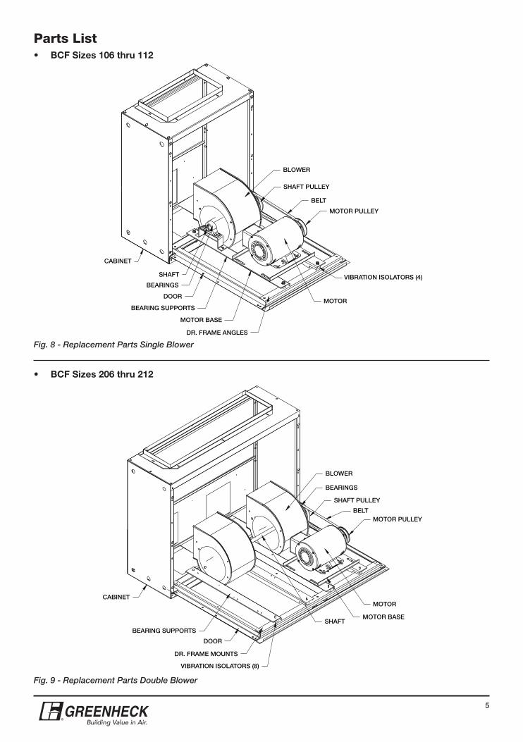
To access the fan motor, drives and blower simply remove the fasteners attaching the bottom access door
and remove door carefully. Hinged access doors are provided on fan models 106, 107, 206, and 207. Provide support for hinged access doors before removing fasteners. The door supports weight of the motor, blower, and drive components. Bolted access doors are provided on fan models 108, 110, 112, 208, 210, and 212. Bolted access doors do not support weight of any components.
BELTS
Belts tend to stretch after a period of time. They should be checked periodically for wear and tightness. When replacing belts, use the same type as supplied with the unit. Loosen the sliding motor plate to allow removal of the belt by hand. Do not force belts on or off. This may cause cords to break, leading to premature belt failure. Once installed, adjust belts as shown in “Pre-Starting Checks”, Fig. 6 and Fig. 7.
MOTOR
Motor maintenance is generally limited to cleaning and lubrication (where applicable). Cleaning should be limited to exterior surfaces only. Removing dust and grease build-up on motor housing assures proper motor cooling. Use a brush or vacuum to remove dust. Motors should never be sprayed with water or solvents.
Greasing of the motor is only intended when fittings are provided. Many motors are permanently lubricated and should not be lubricated further.
Motors supplied with grease fittings should be greased in accordance with manufacturer’s recommendations. Use caution not to over lubricate. Oil spillage collects dust and dirt which may obstruct motor cooling openings.
Where motor temperatures do not exceed 104ºF (40ºC), the grease should
Deflection = Belt Span
62.5 (in.)
Belt Span
(in.)
(in.)
CORRECT WRONG WRONG WRONG
CORRECT WRONG WRONG WRONG
3
®
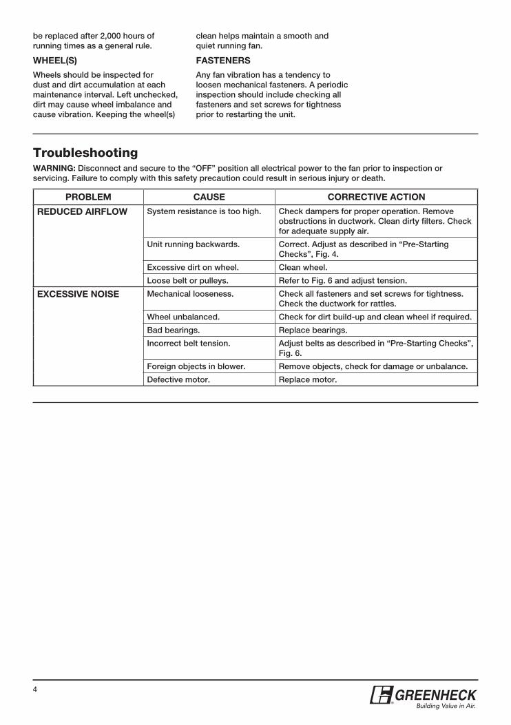
TroubleshootingWARNING: Disconnect and secure to the “OFF” position all electrical power to the fan prior to inspection or servicing. Failure to comply with this safety precaution could result in serious injury or death.
PROBLEM CAUSE CORRECTIVE ACTION
REDUCED AIRFLOW System resistance is too high. Check dampers for proper operation. Remove obstructions in ductwork. Clean dirty filters. Check for adequate supply air.
Unit running backwards. Correct. Adjust as described in “Pre-Starting Checks”, Fig. 4.
Excessive dirt on wheel. Clean wheel.
Loose belt or pulleys. Refer to Fig. 6 and adjust tension.
EXCESSIVE NOISE Mechanical looseness. Check all fasteners and set screws for tightness. Check the ductwork for rattles.
Wheel unbalanced. Check for dirt build-up and clean wheel if required.
Bad bearings. Replace bearings.
Incorrect belt tension. Adjust belts as described in “Pre-Starting Checks”, Fig. 6.
Foreign objects in blower. Remove objects, check for damage or unbalance.
Defective motor. Replace motor.
be replaced after 2,000 hours of running times as a general rule.
WHEEL(S)
Wheels should be inspected for dust and dirt accumulation at each maintenance interval. Left unchecked, dirt may cause wheel imbalance and cause vibration. Keeping the wheel(s)
clean helps maintain a smooth and quiet running fan.
FASTENERS
Any fan vibration has a tendency to loosen mechanical fasteners. A periodic inspection should include checking all fasteners and set screws for tightness prior to restarting the unit.
4
®
BCF Size
*UnitFilter Box Mixing Box
Slide-Out Sloped Without Damper With Damper
10680(36)
9 (229)
24 (610)
14 (356)
29 (737)
107100(45)
10 (254)
26 (660)
17 (432)
36 (914)
108120(54)
12 (305)
39 (991)
23 (584)
45 (1143)
110265(120)
20 (508)
64 (1626)
40 (1016)
69 (1753)
112340(157)
28 (711)
86 (2184)
64 (1626)
100 (2540)
206145(66)
12 (305)
35 (889)
19 (483)
42 (1067)
207207(84)
14 (356)
36 (914)
23 (584)
52 (1321)
208220(100)
17 (432)
50 (1270)
31 (787)
67 (1702)
210345(156)
26 (660)
79 (2007)
51 (1295)
93 (2362)
212515(234)
38 (965)
119 (3023)
86 (2184)
142 (3607)
All weights are in lb. (kg)*Unit weight is cataloged with the largest Open Proof Motor available.
1 in.(25 mm)
G
I
H
E F
L
Fan
Optional Side Acess Door
35/8 in. (92 mm)
Fan
Filter Box
Mixing Box
H
L
L
J
E
F
IK
Fig. 2 - BCF Unit Dimensions Fig. 3 - BCF with Filter and Mixing Box Unit Dimensions
Dimensional Data
Weight Information
BCF Size
E F G H IJ Filter Size
K LSlide-Out Sloped Slide-Out Qty. Sloped Qty.
106231/4(591)
20(508)
-12
(305)6
(152)6
(152)22
(559)191/2 x 101/4 (495 x 260)
116 x 20
(406 x 508)1
21/2(64)
11 (279)
10729
(737)23
(584)5/8(16)
15 (381)
8(203)
6 (152)
23 (584)
227/8 x 121/4 (581 x 311)
116 x 20
(406 x 508)1
21/2(64)
13 (330)
10832
(813)26
(660)5/8(16)
18 (457)
10 (254)
6 (152)
24 (610)
257/8 x 151/2 (657 x 394)
116 x 20
(406 x 508)2
3(76)
16 (406)
11036
(914)32
(813)5/8(16)
24 (610)
12 (305)
7 (178)
25 (635)
317/8 x 181/2 (810 x 470)
120 x 20
(508 x 508)2
31/2(89)
19 (483)
11242
(1067)36
(914)5/8(16)
28 (711)
14 (356)
7 (178)
27 (686)
357/8 x 223/8 (911 x 568)
116 x 20
(406 x 508)4
41/2 (114)
23 (584)
206231/4(591)
34(864)
5/8(16)
26 (660)
6(152)
6 (152)
22 (559)
337/8 x 101/4 (860 x 260)
120 x 20
(508 x 508)1
21/2(64)
11 (279)
20729
(737)38
(965)5/8(16)
30 (762)
8(203)
6 (152)
23 (584)
377/8 x 121/4 (962 x 311)
116 x 20
(406 x 508)2
21/2(64)
13 (330)
20832
(813)44
(1118)5/8(16)
36 (914)
10 (254)
6 (152)
24 (610)
437/8 x 151/2 (1114 x 394)
116 x 20
(406 x 508)4
3(76)
16 (406)
21036
(914)48
(1219)5/8(16)
40 (1016)
12 (305)
7 (178)
25 (635)
477/8 x 181/2 (1216 x 470)
120 x 20
(508 x 508)4
31/2(89)
19 (483)
21242
(1067)58
(1473)5/8(16)
50 (1270)
14 (356)
7 (178)
27 (686)
577/8 x 221/2 (1470 x 572)
120 x 25
(508 x 635)4
41/2 (114)
23 (584)
All dimensions are in inches (mm).
2
®
Pre-Starting ChecksWARNING: Disconnect and secure to the “OFF” position all electrical power to the fan prior to inspection or servicing. Failure to comply with this safety precaution could result in serious injury or death.
Check all fasteners for tightness. The blower wheel should rotate freely and not rub on the fan panel venturi. Turn the fan on momentarily to check for unusual vibration or noise. Do not run the fan more than a few seconds without being connected to the system for which it was designed. Motor overloading and burnout may result from lack of system static pressure.
Direction of wheel rotation is critical. Reversed rotation will result in poor air performance, motor overloading and possible burnout. Check wheel rotation by momentarily energizing the unit. Rotation is always in the same direction as airflow at the outlet. See Fig. 4.
Belt tension should be checked after the first 24 hours of operation, after 100 hours of operation and periodically thereafter. Premature belt failures are frequently caused by improper belt tension (either too tight or loose) or misaligned pulleys. The proper tension for operating a V-belt is the lowest tension at which the belts will not slip.
Belt tension can be adjusted by loosening the four fasteners on the drive frame (pointed out in Fig. 5) and sliding the motor base away from the blower housing.
Belt tension should be adjusted to allow 1/64 inch (0.4 mm) of belt deflection per inch of belt span. For example, a 16 inch (406 mm) belt span should have 16/64 inch (6.4 mm) or 1/4 inch (6.4 mm) of deflection using moderate thumb pressure at mid-point between pulleys, see Fig. 6. Overtightening will cause excessive bearing wear and noise. Too little tension will cause slippage at startup and uneven wear.
It is very important that the pulleys remain in proper alignment after adjustments are made. Misalignment of pulleys will result in premature belt wear, noise, vibration and power loss. See Fig. 7.
Rotation
Airflow
Fig. 4 - Wheel Rotation
Fig. 7 - Pulley Alignment
Fig. 6 - Belt Tension
Fasteners (2)
Fasteners (2)
Fig. 5 - Drive Frame Fasteners
MaintenanceWARNING: Before servicing or cleaning the unit, switch power off at service panel and lock service disconnecting means to prevent power from being switched on accidentally. When the service disconnecting means cannot be locked, securely fasten a prominent warning device, such as a tag, to the service panel.
Once the fan has been put into operation, a periodic maintenance program should be set up to preserve the reliability and performance of the fan. Items to be included in this program are:
BELTS, BEARINGS, MOTOR, FASTENERS, and WHEEL(S).
To access the fan motor, drives and blower simply remove the fasteners attaching the bottom access door
and remove door carefully. Hinged access doors are provided on fan models 106, 107, 206, and 207. Provide support for hinged access doors before removing fasteners. The door supports weight of the motor, blower, and drive components. Bolted access doors are provided on fan models 108, 110, 112, 208, 210, and 212. Bolted access doors do not support weight of any components.
BELTS
Belts tend to stretch after a period of time. They should be checked periodically for wear and tightness. When replacing belts, use the same type as supplied with the unit. Loosen the sliding motor plate to allow removal of the belt by hand. Do not force belts on or off. This may cause cords to break, leading to premature belt failure. Once installed, adjust belts as shown in “Pre-Starting Checks”, Fig. 6 and Fig. 7.
MOTOR
Motor maintenance is generally limited to cleaning and lubrication (where applicable). Cleaning should be limited to exterior surfaces only. Removing dust and grease build-up on motor housing assures proper motor cooling. Use a brush or vacuum to remove dust. Motors should never be sprayed with water or solvents.
Greasing of the motor is only intended when fittings are provided. Many motors are permanently lubricated and should not be lubricated further.
Motors supplied with grease fittings should be greased in accordance with manufacturer’s recommendations. Use caution not to over lubricate. Oil spillage collects dust and dirt which may obstruct motor cooling openings.
Where motor temperatures do not exceed 104ºF (40ºC), the grease should
Deflection = Belt Span
62.5 (in.)
Belt Span
(in.)
(in.)
CORRECT WRONG WRONG WRONG
CORRECT WRONG WRONG WRONG
3
®
TroubleshootingWARNING: Disconnect and secure to the “OFF” position all electrical power to the fan prior to inspection or servicing. Failure to comply with this safety precaution could result in serious injury or death.
PROBLEM CAUSE CORRECTIVE ACTION
REDUCED AIRFLOW System resistance is too high. Check dampers for proper operation. Remove obstructions in ductwork. Clean dirty filters. Check for adequate supply air.
Unit running backwards. Correct. Adjust as described in “Pre-Starting Checks”, Fig. 4.
Excessive dirt on wheel. Clean wheel.
Loose belt or pulleys. Refer to Fig. 6 and adjust tension.
EXCESSIVE NOISE Mechanical looseness. Check all fasteners and set screws for tightness. Check the ductwork for rattles.
Wheel unbalanced. Check for dirt build-up and clean wheel if required.
Bad bearings. Replace bearings.
Incorrect belt tension. Adjust belts as described in “Pre-Starting Checks”, Fig. 6.
Foreign objects in blower. Remove objects, check for damage or unbalance.
Defective motor. Replace motor.
be replaced after 2,000 hours of running times as a general rule.
WHEEL(S)
Wheels should be inspected for dust and dirt accumulation at each maintenance interval. Left unchecked, dirt may cause wheel imbalance and cause vibration. Keeping the wheel(s)
clean helps maintain a smooth and quiet running fan.
FASTENERS
Any fan vibration has a tendency to loosen mechanical fasteners. A periodic inspection should include checking all fasteners and set screws for tightness prior to restarting the unit.
4
®
Model BCF Belt DriveCentrifugal Cabinet Fans
PART # 453284
Please read and save these instructions for future reference. Read carefully before attempting to assemble, install, operate or maintain the unit. Failure to comply with instruction could result in personal injury and/or property damage!
Upon receiving unit, check for any damage that may have occurred during transit and report it immediately to the shipper. Also, check to see that all accessory items are accounted for.
Typical InstallationWARNING: Always disconnect, lock and tag power source before installing or servicing. Failure to disconnect power source can result in fire, shock, serious injury or death.
Move fan to the desired location and determine the position of the access door. Provide adequate door opening clearance for servicing the motor and blower assembly. Attach the fan to a suitable framework as specified. Use of optional hanging or base vibration isolators are recommended. Optional
hanging isolators can be sized to support the weight of the fan only or the fan with filter/mixing boxes. Separate support should be used for ductwork.
The motor voltage and amperage rating must be checked for compatibility with the electrical supply. Supply wiring may be routed through knockouts which are provided on each side of the fan housing. Provide adequate wiring to permit the access door to open for servicing. Wiring should be secured inside the fan to prevent interference with the drive components.
Inlet and discharge collars are provided for duct connection. The inlet panel is removable for attaching optional filter and mixing box accessories.
Hanging or Base Mounts
BCFSize
A B C D
106191/2(493)
421/2(1080)
521/2(1334)
241/4(616)
10725
(635)473/4
(1213)603/4
(1543)271/4(692)
10829
(737)523/8
(1330)69
(1753)301/4(768)
110291/2 (749)
561/8(1426)
75(1905)
361/4(921)
11238
(965)647/8
(1648)873/4
(2229)401/2
(1029)
206191/2 (493)
421/2(1080)
521/2(1334)
381/4(972)
20725
(635)473/4
(1213)603/4
(1543)421/4
(1073)
20829
(737)523/8
(1330)69
(1753)481/4
(1226)
210291/2 (749)
561/8(1426)
75(1905)
521/4(1327)
21238
(965)647/8
(1648)873/4
(2229)621/4
(1581)
All dimensions are in inches (mm).
NOTE: Only four (4) hanging or base mounts required per unit.
WarranTyGreenheck warrants this equipment to be free from defects in material and workmanship for a period of one year from the date of purchase. Any units or parts which prove to be defective during the warranty period will be replaced at our option when returned to our factory, transportation prepaid. Motors are warranted by the motor manufacturer for a period of one year. Should motors furnished by Greenheck prove defective during this period, they should be returned to the nearest authorized motor service station. Greenheck will not be responsible for any removal or installation costs.
As a result of our commitment to continuous improvement, Greenheck reserves the right to change specifications without notice.