WARNING: Read instructions completely before installation and retain for future reference. WARNING: WARNING: CAUTION: CAUTION OTHER CAUTIONS: For installation and/or use in accordance with appropriate electrical codes and regulations. Consult a qualified electrician for installation and operation. To avoid overheating and possible damage to this device and connected equipment, do not attempt to control a receptacle, fluorescent lighting, motor, or transformer. (For Incandescent Only): USE WITH INCANDESCENT OR 120V HALOGEN FIXTURES ONLY. 1. Use only one (1) dimmer per load. For remote operation, use standard 3-way or 4-way electrical devices for ON/OFF operation or use with Z-Wave compatible control for wireless control from any location. 2. Use Air-Gap switch to disconnect power when servicing or changing lamp. 3. Use this device only with 75°C rated copper or copper clad wire. Model CA600 Single-Pole / Multi-Pole Dimmer 600 Watt Switch Specifications: Ratings: Colors: Connections: RF Information: Network Information: Single-Pole (One Location) or 3-Way (Multi-Location) or Wireless RF Control 120VAC, 50/60Hz Maximum Wattage: 600W Minimum Wattage: 40W Includes white, ivory, and light almond snap-on rocker plates. Black-Line, Blue-Load, Red-Traveler, Green-Ground Minimum Range: 50ft indoor; 100ft outdoor Frequency: 908.42 MHz Mesh Network - Each line powered node acts as a repeater to route distant signals. Data Rate: 9600 bits/second Size: 232 Z-Wave™ Nodes Operating Temperature Range: 32°F (0°C) to 104°F (40°C) Power Consumption: 3.0W Max Fade-on& Fade-off 1% Dimming (100 Increments) Dimming: INSTALLATION: 1. WARNING: TO AVOID FIRE, SHOCK, OR DEATH, TURN OFF POWER AT CIRCUIT BREAKER AND TEST THAT POWER IS OFF BEFORE WIRING. Operation: 2. For retrofit applications, remove wall plate and disconnect light switch. 3. Refer to wiring diagrams for proper connection of dimmer for intended application. 4. Check that all wire connections are secure. 5. Place all wires inside junction box. Install dimmer using (2) mounting screws furnished. Complete installation with a decorator style wall-plate. 6. Reconnect your electrical power. 7. Tap top of rocker to turn lights on; tap bottom of rocker to turn lights off; press and hold top of rocker to brighten connected load; press and hold bottom of rocker to dim connected load. 8. For programming instructions refer to the (158CA12789). InTouch Installer & Users Guide The CA600 In-Wall Dimmer is a Z-wave™ enabled device which is fully compatible with any Z-wave enabled network. Z-wave enabled devices display the Z-wave logo and guarantee connectivity and interoperability between devices. Each line powered node in a Z-wave network is designed to act as a repeater forming a mesh network eliminating radio “dead spots” and providing the highest level of reliability. - Multiple location dimming when used with wireless accessory controls. - Multiple location On/Off control using conventional 3-way or 4-way wiring and devices. - Lights fade up or down turned on or off. - Automatically returns to last level in the event of power fluctuations. - Light levels can be set by pressing and holding the rocker until the desired light level is reached. - Mini-scenes allows local control of connected load plus up to 5 additional Z-wave devices. - Full 230 device scene control when used with Intermatic InTouch™ server . - Dimmer always operates local load, does not require central control system. Features On/Off and (CA5500B) Rocker Color Conversion The frame and rocker color of this device can be converted to match interior design requirements. Simply use one of the included color plates (white, ivory, or light almond) and proceed as follows (please note that the device must be removed from the junction box to change the rocker, follow the installation instructions and warnings). 1. Select the color of the face you desire. 2. The frame has snaps on its sides. Using a small screwdriver or thumbnail, gently remove the frame and rocker from the housing body. 3. Take the new frame and position it properly to the housing body. Notice that the locking snaps will align in only the proper direction. Line up the plastic snaps with the slots in the housing body and snap into place. 4. The frame snaps in with an audible click. Ensure that both snaps are secure. Replace the device in the junction box following installation instructions. The color conversion is complete. Rocker Frame Snap FCC STATEMENT OF COMPLIANCE WARNING! Changes or modifications not expressly approved by Intermatic Inc. could void the user’s authority to operate the equipment. This device complies with part 15 of the FCC rules. Operation of this device is subject to the following two conditions: (1) This device may not cause harmful interference, and (2) This device must accept any interference, including interference that may cause undesired operation. NOTE: This equipment has been tested and found to comply with the limits for a Class B digital device, pursuant to Part 15 of the FCC Rules. These limits are designed to provide reasonable protection against harmful interference in a residential installation. This equipment generates, uses and can radiate radio frequency energy and, if not installed and used in accordance with the instructions, may cause harmful interference to radio communications. However, there is no guarantee that interference will not occur in a particular installation. If this equipment does cause harmful interference to radio or television reception, which can be determined by turning the equipment off and on, the user is encouraged to try to correct the interference by one or more of the following measures: -- Reorient or relocate the receiving antenna or device. -- Increase the separation between the equipment and receiver. -- Connect the equipment into an outlet on a circuit different from that to which the receiver is connected. -- Consult the dealer or an experienced radio/TV technician for help. Note: Air-Gap switch should be used to remove power from connected loads before servicing.
Transcript
WARNING: Read instructions completely before installation and retain for future reference.WARNING: WARNING: CAUTION:
CAUTIONOTHER CAUTIONS:
For installation and/or use in accordance with appropriate electrical codes and regulations. Consult a qualified electrician for installation and operation.
To avoid overheating and possible damage to this device and connected equipment, do not attempt to control a receptacle, fluorescent lighting, motor, or transformer.
(For Incandescent Only): USE WITH INCANDESCENT OR 120V HALOGEN FIXTURES ONLY.
1. Use only one (1) dimmer per load. For remote operation, use standard 3-way or 4-way electrical devices for ON/OFF operation or use with Z-Wave compatible control for wireless control from any location.2. Use Air-Gap switch to disconnect power when servicing or changing lamp.3. Use this device only with 75°C rated copper or copper clad wire.
Model CA600Single-Pole / Multi-Pole
Dimmer 600 Watt Switch
Specifications:
Ratings:
Colors:
Connections:
RF Information:
Network Information:
Single-Pole (One Location) or 3-Way (Multi-Location) or Wireless RF Control
Mesh Network - Each line powered node acts as a repeater to route distant signals.Data Rate: 9600 bits/secondSize: 232 Z-Wave™ Nodes
Operating Temperature Range: 32°F (0°C) to 104°F (40°C)Power Consumption: 3.0W Max
Fade-on& Fade-off1% Dimming (100 Increments)
Dimming:
INSTALLATION:1. WARNING: TO AVOID FIRE, SHOCK, OR DEATH, TURN OFF POWER AT CIRCUIT BREAKER AND TEST THAT POWER IS OFF BEFORE WIRING.
Operation:
2. For retrofit applications, remove wall plate and disconnect light switch. 3. Refer to wiring diagrams for proper connection of dimmer for intended application.4. Check that all wire connections are secure. 5. Place all wires inside junction box. Install dimmer using (2) mounting screws furnished. Complete installation with a decorator style wall-plate.6. Reconnect your electrical power.7. Tap top of rocker to turn lights on; tap bottom of rocker to turn lights off; press and hold top of rocker to brighten connected load; press and hold bottom of rocker to dim connected load.8. For programming instructions refer to the (158CA12789).InTouch Installer & Users Guide
The CA600 In-Wall Dimmer is a Z-wave™ enabled device which is fully compatible with any Z-wave enabled network. Z-wave enabled devices display the Z-wave logo and guarantee connectivity and interoperability between devices. Each line powered node in a Z-wave network is designed to act as a repeater forming a mesh network eliminating radio “dead spots” and providing the highest level of reliability.
- Multiple location dimming when used with wireless accessory controls.- Multiple location On/Off control using conventional 3-way or 4-way wiring and devices.- Lights fade up or down turned on or off.- Automatically returns to last level in the event of power fluctuations.- Light levels can be set by pressing and holding the rocker until the desired light level is reached.- Mini-scenes allows local control of connected load plus up to 5 additional Z-wave devices.- Full 230 device scene control when used with Intermatic InTouch™ server .- Dimmer always operates local load, does not require central control system.
FeaturesOn/Off and
(CA5500B)
Rocker Color ConversionThe frame and rocker color of this device can be converted to match interior design requirements. Simply use one of the included color plates (white, ivory, or light almond) and proceed as follows (please note that the device must be removed from the junction box to change the rocker, follow the installation instructions and warnings).1. Select the color of the face you desire.2. The frame has snaps on its sides. Using a small screwdriver or thumbnail, gently remove the frame and rocker from the housing body. 3. Take the new frame and position it properly to the housing body. Notice that the locking snaps will align in only the proper direction. Line up the plastic snaps with the slots in the housing body and snap into place. 4. The frame snaps in with an audible click. Ensure that both snaps are secure. Replace the device in the junction box following installation instructions.The color conversion is complete.
Rocker Frame Snap
FCC STATEMENT OF COMPLIANCE
WARNING! Changes or modifications not expressly approved by Intermatic Inc. could void the user’s authority to operate the equipment.
This device complies with part 15 of the FCC rules. Operation of this device is subject to the following two conditions:(1) This device may not cause harmful interference, and(2) This device must accept any interference, including interference that may cause undesired operation.
NOTE: This equipment has been tested and found to comply with the limits for a Class B digital device, pursuant to Part 15 of the FCC Rules. These limits are designed to provide reasonable protection against harmful interference in a residential installation. This equipment generates, uses and can radiate radio frequency energy and, if not installed and used in accordance with the instructions, may cause harmful interference to radio communications. However, there is no guarantee that interference will not occur in a particular installation. If this equipment does cause harmful interference to radio or television reception, which can be determined by turning the equipment off and on, the user is encouraged to try to correct the interference by one or more of the following measures:
-- Reorient or relocate the receiving antenna or device.-- Increase the separation between the equipment and receiver.-- Connect the equipment into an outlet on a circuit different from that to which the receiver is connected.-- Consult the dealer or an experienced radio/TV technician for help.
Note: Air-Gap switch should be used to remove power from connected loads before servicing.
158CA12471.indd 1 11/6/06 4:30:45 PM
Single Pole Application
Hot Black
Neutral
Blue
IncandescentLighting LoadRed
Wire Connector Ground
Green120VAC50/60 Hz
3-Way Application
Hot Black
Neutral
Blue
IncandescentLighting LoadRed
Wire Connector Ground
120VAC50/60 Hz
Jumper
CA600 CA600 CA-3PS / Standard 3-Way Switch
Multi-Way Application
Hot Black
Neutral
Blue
IncandescentLighting LoadRed
Wire Connector Ground
120VAC50/60 Hz
CA600 CA-3PS / Standard 3-Way SwitchCA-4PS / Standard 4-Way SwitchCA-3PS / Standard 3-Way Switch CA-4PS / Standard 4-Way Switch
Green
Green
Wire Connector InstallationConnect wires per Single Pole, 3-Way, or Multi-Way Application Diagrams as follows:Screw wire connectors on clockwise making sure no bare conductors show below the wire connector. Secure each connector with electrical tape.
Insert wires straightthen twist clockwise
Secure each connnectorwith electrical tape
Maximum Load Per Dimmer for Multiple DevicesCat. No.
CA600
Single
600 Watt
Two Devices
500 Watt
Three or More
400 Watt
For non-standard wiring applications, refer toWire Combination & Connector Chart
Orange Wire Connector Combination Chart
1- #14 AWG
1 #14 AWGor
1 #16 AWGor
1-2 #18 AWG
+1- #16 AWG
1 #16 AWGor
1-2 #18 AWG
+2- #16 AWG
1 to 2 #18 AWG
+1- #18 AWG
1 to 3 #18 AWG
+
Strip wires to expose3/8” of conductors
3/8”
LIMITED TEN YEAR WARRANTYIf within ten (10) years from date of purchase, this product fails due to a defect in material or workmanship, Intermatic Incorporated will repair or replace, at its sole option. This warranty applies only to the original purchaser and is not transferable. This warranty excludes and this is disclaimed liability for labor for removal of this product or reinstallation. The warranty does not apply to: (a) damage caused by accident, abuse , mishandling, dropping, acts of God, or any negligent use; (b) units which have been subject to unauthorized repair, opened taken apart, or otherwise modified; (c) units not used in accordance with directions; (d) damages exceeding the cost of the procudt. Some states do not allow a limitation of damages, so the foregoing limitation may not app;y to you. This warranty gives you specific legal rights and you may have other rights that vary from state to state. INTERMATIC INCORPORATED WILL NOT BE LIABLE FOR INCIDENTAL OR CONSEQUENTIAL DAMAGES. THIS WARRANTY IS IN LIEU OF ALL OTHER EXPRESS OR IMPLIED WARRANTIES. ALL IMPLIED WARRANTIES, INCLUDING THE WARRANTY OF MERCHANTABILITY AND THE WARRANTY OF FITNESS FOR A PARTICULAR PURPOSE, ARE HEREBY MODIFIED TO EXIST ONLY AS CONTAINED IN THIS LIMITED WARRANTY, AND SHALL BE OF THE SAME DURATION AS THE WARRANTY PERIOD STATED ABOVE.This warranty service is available by either (a) returning the product to the dealer from whom the unit was purchased, or (b) mailing the product, along with proof of purchase, postage prepaid to the authorized service center listed below. This warranty is made by: Intermatic Incorporated/AfterSales Service 7777 Winn Rd., Spring Grove, Illinois 60081-9698/815-675-7100 http://www.intermatic.com Please be sure to wrap the product securely to avoid shipping damage.
158CA12471
158CA12471.indd 2 11/6/06 4:30:45 PM
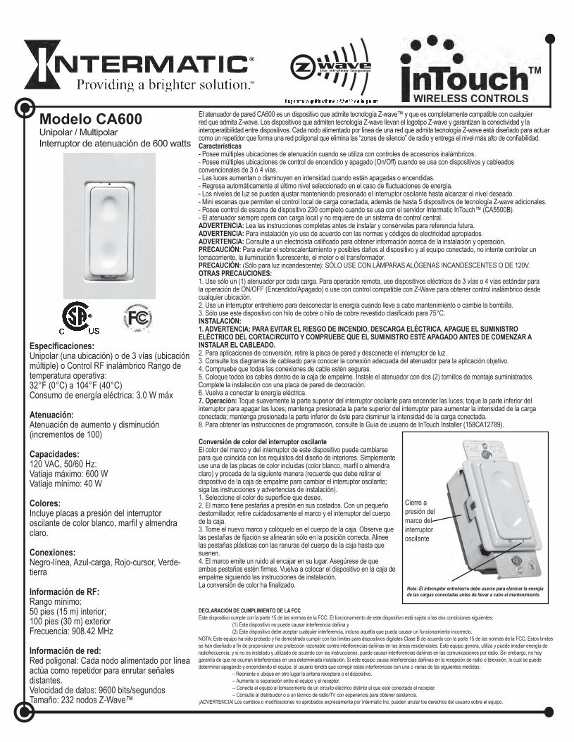
Modelo CA600Unipolar / Multipolar Interruptor de atenuación de 600 watts
Especificaciones: Unipolar (una ubicación) o de 3 vías (ubicación múltiple) o Control RF inalámbrico Rango de temperatura operativa: 32°F (0°C) a 104°F (40°C) Consumo de energía eléctrica: 3.0 W máx
Atenuación: Atenuación de aumento y disminución (incrementos de 100)
Información de RF: Rango mínimo: 50 pies (15 m) interior; 100 pies (30 m) exterior Frecuencia: 908.42 MHz
Información de red: Red poligonal: Cada nodo alimentado por línea actúa como repetidor para enrutar señales distantes. Velocidad de datos: 9600 bits/segundos Tamaño: 232 nodos Z-Wave™
El atenuador de pared CA600 es un dispositivo que admite tecnología Z-wave™ y que es completamente compatible con cualquier red que admita Z-wave. Los dispositivos que admiten tecnología Z-wave llevan el logotipo Z-wave y garantizan la conectividad y la interoperatibilidad entre dispositivos. Cada nodo alimentado por línea de una red que admita tecnología Z-wave está diseñado para actuar como un repetidor que forma una red poligonal que elimina las “zonas de silencio” de radio y entrega el nivel más alto de confiabilidad. Características - Posee múltiples ubicaciones de atenuación cuando se utiliza con controles de accesorios inalámbricos. - Posee múltiples ubicaciones de control de encendido y apagado (On/Off) cuando se usa con dispositivos y cableados convencionales de 3 ó 4 vías. - Las luces aumentan o disminuyen en intensidad cuando están apagadas o encendidas. - Regresa automáticamente al último nivel seleccionado en el caso de fluctuaciones de energía. - Los niveles de luz se pueden ajustar manteniendo presionado el interruptor oscilante hasta alcanzar el nivel deseado. - Mini escenas que permiten el control local de carga conectada, además de hasta 5 dispositivos de tecnología Z-wave adicionales. - Posee control de escena de dispositivo 230 completo cuando se usa con el servidor Intermatic InTouch™ (CA5500B). - El atenuador siempre opera con carga local y no requiere de un sistema de control central. ADVERTENCIA: Lea las instrucciones completas antes de instalar y consérvelas para referencia futura.ADVERTENCIA: Para instalación y/o uso de acuerdo con las normas y códigos de electricidad apropiados. ADVERTENCIA: Consulte a un electricista calificado para obtener información acerca de la instalación y operación.PRECAUCIÓN: Para evitar el sobrecalentamiento y posibles daños al dispositivo y al equipo conectado, no intente controlar un tomacorriente, la iluminación fluorescente, el motor o el transformador. PRECAUCIÓN: (Sólo para luz incandescente): SÓLO USE CON LÁMPARAS ALÓGENAS INCANDESCENTES O DE 120V. OTRAS PRECAUCIONES: 1. Use sólo un (1) atenuador por cada carga. Para operación remota, use dispositivos eléctricos de 3 vías o 4 vías estándar para la operación de ON/OFF (Encendido/Apagado) o use con control compatible con Z-Wave para obtener control inalámbrico desde cualquier ubicación. 2. Use un interruptor entrehierro para desconectar la energía cuando lleve a cabo mantenimiento o cambie la bombilla. 3. Sólo use este dispositivo con hilo de cobre o hilo de cobre revestido clasificado para 75°C.INSTALACIÓN: 1. ADVERTENCIA: PARA EVITAR EL RIESGO DE INCENDIO, DESCARGA ELÉCTRICA, APAGUE EL SUMINISTRO ELÉCTRICO DEL CORTACIRCUITO Y COMPRUEBE QUE EL SUMINISTRO ESTÉ APAGADO ANTES DE COMENZAR A INSTALAR EL CABLEADO. 2. Para aplicaciones de conversión, retire la placa de pared y desconecte el interruptor de luz. 3. Consulte los diagramas de cableado para conocer la conexión adecuada del atenuador para la aplicación objetivo. 4. Compruebe que todas las conexiones de cable estén seguras. 5. Coloque todos los cables dentro de la caja de empalme. Instale el atenuador con dos (2) tornillos de montaje suministrados. Complete la instalación con una placa de pared de decoración. 6. Vuelva a conectar la energía eléctrica. 7. Operación: Toque suavemente la parte superior del interruptor oscilante para encender las luces; toque la parte inferior del interruptor para apagar las luces; mantenga presionada la parte superior del interruptor para aumentar la intensidad de la carga conectada; mantenga presionada la parte inferior de éste para disminuir la intensidad de la carga conectada. 8. Para obtener las instrucciones de programación, consulte la Guía de usuario de InTouch Installer (158CA12789).
Conversión de color del interruptor oscilanteEl color del marco y del interruptor de este dispositivo puede cambiarse para que coincida con los requisitos del diseño de interiores. Simplemente use una de las placas de color incluidas (color blanco, marfil o almendra claro) y proceda de la siguiente manera (recuerde que debe retirar el dispositivo de la caja de empalme para cambiar el interruptor oscilante; siga las instrucciones y advertencias de instalación). 1. Seleccione el color de superficie que desee. 2. El marco tiene pestañas a presión en sus costados. Con un pequeño destornillador, retire cuidadosamente el marco y el interruptor del cuerpo de la caja. 3. Tome el nuevo marco y colóquelo en el cuerpo de la caja. Observe que las pestañas de fijación se alinearán sólo en la posición correcta. Alinee las pestañas plásticas con las ranuras del cuerpo de la caja hasta que suenen. 4. El marco emite un ruido al encajar en su lugar. Asegúrese de que ambas pestañas estén firmes. Vuelva a colocar el dispositivo en la caja de empalme siguiendo las instrucciones de instalación. La conversión de color ha finalizado.
DECLARACIÓN DE CUMPLIMIENTO DE LA FCCEste dispositivo cumple con la parte 15 de las normas de la FCC. El funcionamiento de este dispositivo está sujeto a las dos condiciones siguientes: (1) Este dispositivo no puede causar interferencia dañina y (2) Este dispositivo debe aceptar cualquier interferencia, incluso aquélla que pueda causar un funcionamiento incorrecto. NOTA: Este equipo ha sido probado y ha demostrado cumplir con los límites para dispositivos digitales Clase B de acuerdo con la parte 15 de las normas de la FCC. Estos límites se han diseñado a fin de proporcionar una protección razonable contra interferencias dañinas en las áreas residenciales. Este equipo genera, utiliza y puede irradiar energía de radiofrecuencia, y si no es instalado y utilizado de acuerdo con las instrucciones, puede causar interferencias dañinas en las comunicaciones por radio. Sin embargo, no hay garantía de que no ocurran interferencias en una determinada instalación. Si este equipo causa interferencias dañinas en la recepción de radio o televisión, lo cual se puede determinar apagando y encendiendo el equipo, el usuario tendrá que corregir estas interferencias con una o varias de las siguientes medidas: – Reoriente o ubique en otro lugar la antena receptora o el dispositivo. -- Aumente la separación entre el equipo y el receptor. -- Conecte el equipo al tomacorriente de un circuito eléctrico distinto al que esté conectado el receptor. -- Consulte al distribuidor o a un técnico de radio/TV con experiencia para obtener asistencia. ¡ADVERTENCIA! Los cambios o modificaciones no aprobados expresamente por Intermatic Inc. pueden anular los derechos del usuario sobre el equipo.
Cierre a presión del marco del interruptor oscilante
Nota: El interruptor entrehierro debe usarse para eliminar la energía de las cargas conectadas antes de llevar a cabo el mantenimiento.
158CA12471SP.indd 1 11/6/06 4:31:18 PM
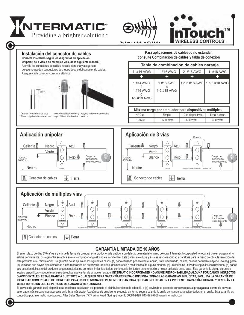
Instalación del conector de cablesConecte los cables según los diagramas de aplicación Unipolar, de 3 vías o de múltiples vías, de la siguiente manera: Atornille los conectores de cables hacia la derecha y asegúrese de que no queden conductores desnudos debajo del conector de cables. Asegure cada conector con cinta eléctrica.
Quite un revestimiento de unos 3/8 de pulgada de los conductores
Inserte los cables derechos y luego dóblelos a la derecha
Asegure cada conector con cinta eléctrica
Para aplicaciones de cableado no estándar, consulte Combinación de cables y tabla de conexión
GARANTÍA LIMITADA DE 10 AÑOSSi en un plazo de diez (10) años a partir de la fecha de compra, este producto falla debido a un defecto de material o mano de obra, Intermatic Incorporated lo reparará o reemplazará, si lo estima conveniente. Esta garantía se aplica sólo al comprador original y no es transferible. Esta garantía excluye y ésta es responsabilidad aclaratoria para la mano de obra, la remoción de este producto o su reinstalación. La garantía no se aplica en los siguientes casos: (a) daño causado por accidente, abuso, trato inadecuado, caídas, causas de fuerza mayor o uso negligente; (b) unidades que hayan sido sometidas a una reparación no autorizada, abiertas, desmontadas o modificadas de alguna manera; (c) unidades no utilizadas según las instrucciones; (d) daños que excedan del costo del producto. Algunos estados no permiten limitar los daños, por lo que la limitación anterior pudiera no ser aplicable en su caso. Esta garantía le otorga derechos legales específicos y puede tener otros derechos que varíen de estado en estado. INTERMATIC INCORPORATED NO ASUME RESPONSABILIDAD ALGUNA POR DAÑOS INDIRECTOS O ACCIDENTALES. ESTA GARANTÍA SUSTITUYE A CUALQUIER OTRA GARANTÍA EXPRESA O IMPLÍCITA. TODAS LAS GARANTÍAS IMPLÍCITAS, INCLUIDA LA GARANTÍA DE IDONEIDAD COMERCIAL O DE IDONEIDAD PARA UN DETERMINADO FIN, SE MODIFICAN PARA QUEDAR INCLUIDAS EN LA PRESENTE GARANTÍA LIMITADA, Y TENDRÁN LA MISMA DURACIÓN QUE EL PERIODO DE GARANTÍA MENCIONADO. El servicio de garantía está disponible (a) mediante devolución del producto al distribuidor donde lo adquirió, o (b) enviando el producto por correo postal prepagado al centro de servicio autorizado más cercano que aparezca en la lista más abajo. Asegúrese de envolver el producto en forma segura cuando lo envíe por correo para evitar daños en el envío. Esta garantía es concedida por: Intermatic Incorporated, After Sales Service, 7777 Winn Road, Spring Grove, IL 60081-9698, 815-675-7000 www.intermatic.com
158CA12471SP.indd 2 11/6/06 4:31:19 PM
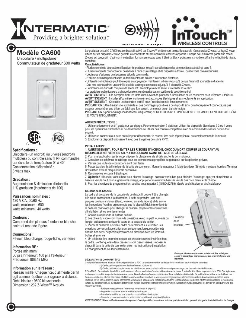
Modèle CA600Unipolaire / multipolaire Commutateur de gradateur 600 watts
Spécifications : Unipolaire (un endroit) ou 3 voies (endroits multiples) ou contrôle sans fil RF commandée par échelle de température 0° à 40° Consommation d’électricité : 3 watts max.
Information RF : Portée minimum : 50 pi à l’intérieur; 100 pi à l’extérieur Fréquence 908.42 MHz
Information sur le réseau :Réseau maillé Chaque nœud alimenté par fil agit comme répéteur aux signaux à distance. Débit binaire : 9600 bits/seconde Dimension : 232 Z-Wave™ Nœuds
Le gradateur encastré CA600 est un dispositif activé par Z-wave™ entièrement compatible avec le réseau activé Z-wave. Le logo Z-wave affiché sur les dispositifs Z-wave garantit la connectivité et l’interopérabilité entre les appareils. Chaque nœud alimenté par fil d’un réseau Z-wave est conçu afin d’agir comme répéteur formant un réseau sans fil éliminant les « points morts » radio et offrant une fiabilité de niveau supérieur. Caractéristiques- Plusieurs endroits pour activer/désactiver le gradateur lorsqu’il est utilisé avec des commandes accessoires sans fil. - Plusieurs endroits pour activer et désactiver à l’aide d’un câblage et de dispositifs à trois ou quatre voies conventionnelles. - L’éclairage s’estompe ou s’accentue selon la commande. - S’allume automatiquement selon la dernière intensité en cas d’interruption électrique. - L’intensité de l’éclairage peut être réglée en appuyant et maintenant la bascule jusqu’à ce que l’intensité souhaitée soit atteinte. - Des mini scènes offrent un contrôle local de la charge connectée et jusqu’à 5 dispositifs Z-wave. - Commande de dispositif complète de scène 230 si employé avec le serveur Intermatic InTouch™. - Le gradateur opère toujours la charge locale et ne nécessite pas un système de contrôle central. AVERTISSEMENT : Lire complètement les instructions avant de procéder à l’installation et les conserver pour référence ultérieure. AVERTISSEMENT : Installer et/ou utiliser conformément aux codes électriques et aux règlements en application.AVERTISSEMENT : Consulter un électricien certifié pour l’installation et le fonctionnement.PRÉCAUTION : Afin d’éviter une surchauffe et des dommages possibles à ce dispositif ainsi qu’à l’équipement connecté, ne pas essayer de contrôler une prise, un éclairage fluorescent, un moteur ou un transformateur. PRÉCAUTION : (pour éclairage incandescent uniquement) : EMPLOYER AVEC UN ÉCLAIRAGE INCANDESCENT OU HALOGÈNE 120 VOLTS UNIQUEMENT.
AUTRES PRÉCAUTIONS : 1. Utiliser uniquement un (1) gradateur par charge. Pour une opération à distance, utiliser les dispositifs électriques à 3 ou 4 voies pour les opérations d’activation et de désactivation ou utiliser des contrôle compatible avec des commandes sans fil depuis tout endroit. 2. Utiliser un commutateur avec entrefer pour déconnecter le courant lors de la réparation ou du remplacement de l’ampoule. 3. Employer ce dispositif uniquement avec des fils gainés de cuivre 75°C.
INSTALLATION : 1. AVERTISSEMENT : POUR ÉVITER LES RISQUES D’INCENDIE, CHOC OU MORT, COUPER LE COURANT AU DISJONCTEUR ET VÉRIFIER S’IL Y A DU COURANT AVANT DE FAIRE LE CÂBLAGE. 2. Pour une application après coup, déposer la plaque murale et débrancher le commutateur. 3. Consulter les schémas de câblage pour les connexions appropriées du gradateur sur l’application prévue. 4. Vérifier que toutes les connexions sont bien faites 5. Placer tous les fils à l’intérieur de la boîte de connexion. Monter le gradateur à l’aide des deux (2) vis de montage fournies. Terminer l’installation avec la plaque murale décorative. 6. Reconnectez le courant électrique. 7. Opération : Basculer vers le haut pour allumer l’éclairage; basculer ver le bas pour éteindre l’éclairage; appuyer et maintenir la bascule vers le haut pour augmenter la charge, appuyer et maintenir la bascule vers le bas pour diminuer la charge. 8. Pour les directives de programmation, veuillez vous reporter à (158CA12789). Guide de l’utilisateur et de l’installateur.
Couleur de la bascule Le cadre et la couleur de la bascule de ce dispositif peuvent être changés afin de se coordonner à la décoration. Il suffit de prendre l’une des plaques couleurs incluses (blanc, ivoire ou amande légère) et de suivre les instructions (veuillez prendre note que le dispositif doit être enlevé de la boîte de connexion pour changer la bascule, respecter les instructions d’installation et les avertissements). 1. Choisir la couleur de la surface désirée. 2. Les côtés du cadre sont munis de pressions. Avec un petit tournevis ou l’ongle, délicatement enlever le cadre et la bascule du boîtier. 3. Placer et centrer le nouveau cadre correctement sur le boîtier. Les pressions de verrouillage s’aligneront uniquement lorsque positionnés dans le bon sens. Aligner les pressions en plastique avec les fentes du boîtier et enfoncer. 4. Un déclic se fera entendre lorsque les pressions seront insérées dans le cadre. Vérifier que les deux pressions sont bien insérées. Reposer le dispositif dans la boîte de connexion selon les instructions d’installation. Le changement de couleur est terminé.
DÉCLARATION DE CONFORMITÉ FCC Ce dispositif est conforme à l’article 15 des règlements de la FCC. Le fonctionnement de ce dispositif est soumis aux deux conditions suivantes : (1) Ce dispositif ne peut causer des interférences nuisibles et (2) Ce dispositif doit accepter toutes les interférences, y compris les interférences qui peuvent engendrer des opérations indésirables. REMARQUE : Ce matériel a été vérifié et a été reconnu conforme aux limites d’un dispositif numérique de classe B, selon l’article 15 des règlements de la FCC. Ces règlements sont conçus pour offrir une protection raisonnable contre d’éventuelles interférences nuisibles lors d’une installation résidentielle. Ce matériel émet, utilise et peut diffuser des fréquences radio qui, s’il n’est pas installé et utilisé conformément aux directives ci-après, peuvent engendrer des interférences nuisibles dans les communications radios. Toutefois, il n’y a pas de garantie qu’une interférence ne surviendra pas dans une installation particulière. Si cet instrument produit des interférences nuisibles à la réception de la radio ou de la télévision, ce qui peut être déterminé en mettant sous tension et hors tension l’instrument, l’usager est invité à essayer de les corriger en appliquant l’une des mesures suivantes. – Rediriger ou repositionner l’antenne de réception ou le dispositif. – Augmenter la distance entre le matériel et le récepteur. – Brancher le matériel sur une prise d’un circuit différent du récepteur. – Consulter un concessionnaire ou un technicien expérimenté en radio et télévision. AVERTISSEMENT ! Une modification ou un changement n’ayant pas été expressément autorisé par Intermatic Inc. pourrait abroger le droit d’utilisation de l’usager.
Pression de la bascule
Remarque: Un commutateur avec entrefer doit être utilisé pour couper le courant des charges connectées avant d’effectuer une réparation.
158CA12471FR.indd 1 11/6/06 4:31:42 PM
Installation du connecteur de fil Connecter les fils selon les schémas d’application unipolaire, 3 voies ou voies multiples, comme suit : Visser les connecteurs de fils dans le sens horaire, en s’assurant qu’il n’y a pas d’âme visible sous le connecteur de fil. Fixer chaque connecteur avec du ruban isolant.
Dénuder les fils afin d’exposer 3/8 po d’âme
Insérer les fils tout droit en lestordant dans le sens horaire
Fixer chaque connecteur avec du ruban isolant
Pour les applications non standard, veuillez consulter le tableau de combinaison de câblage et de connecteur
GARANTIE LIMITÉE DIX ANSSi, dans les dix (10) ans qui suivent la date d’achat, ce dispositif présente une défectuosité de matériel ou de fabrication, Intermatic Incorporated s’engage à le réparer ou le remplacer, à sa seule discrétion. Cette garantie s’applique uniquement à l’acheteur original et est incessible. Cette garantie exclus et rejette toute responsabilité pour la main d’œuvre nécessaire à la dépose et à la réinstallation de cet article. La garantie ne s’applique pas: (a) aux dommages causés par un accident, abus, mauvaise manipulation, chute, catastrophe naturelle ou utilisation négligente ; (b) aux dispositifs soumis à des réparations non autorisées, qui ont été ouverts, démontés ou modifiés de quelconque manière ; (c) aux dispositifs qui ne sont pas utilisés conformément aux di-rectives ; (d) aux dommages dépassant le coût du produit; (d) aux dommages dépassant le coût du produit. Certains états n’autorisent pas l’exclusion ou la limitation de dommages accidentels ou consécutifs, dans tel cas, les limites ci-dessus ne s’appliquent pas à vous. Cette garantie vous accorde des droits légaux spécifiques et vous pouvez avoir d’autres droits selon l’état dans lequel vous résidez. INTERMATIC INCORPORATED NE POURRA ÊTRE TENUE RESPONSABLE DE DOMMAGES ACCIDENTELS OU CONSÉCUTIFS. CETTE GARANTIE REMPLACE TOUTES LES AUTRES GARANTIES EXPRESSES OU IMPLICITES. TOUTES LES GARANTIES IMPLICITES, Y COMPRIS LA GARANTIE DE COMMERCIALISATION ET LA GARANTIE DE CONFORMITÉ À UNE FIN PRÉVUE, SONT PAR LA PRÉSENTE MODIFIÉES POUR EXISTER UNIQUEMENT TEL QUE CONTENUE DANS LA GARANTIE LIMITÉE, ET AURONT LA MÊME DURÉE QUE LA PÉRIODE DE GARANTIE DÉCLARÉE CI-DESSUS. Le service de garantie est disponible soit (a) en retournant le produit au vendeur auprès de qui le dispositif a été acheté, ou (b) en expédiant par la poste, port payé au centre de service agréé le plus près. Veuillez vous assurer que le produit est convenablement emballé pour éviter des dégâts pendant le transport. Cette garantie est accordée par: Intermatic Incorporated/Service après-vente / 7777 Winn Road., Spring Grove, IL 60081-9698/815-675-7000 www.intermatic.com.