2
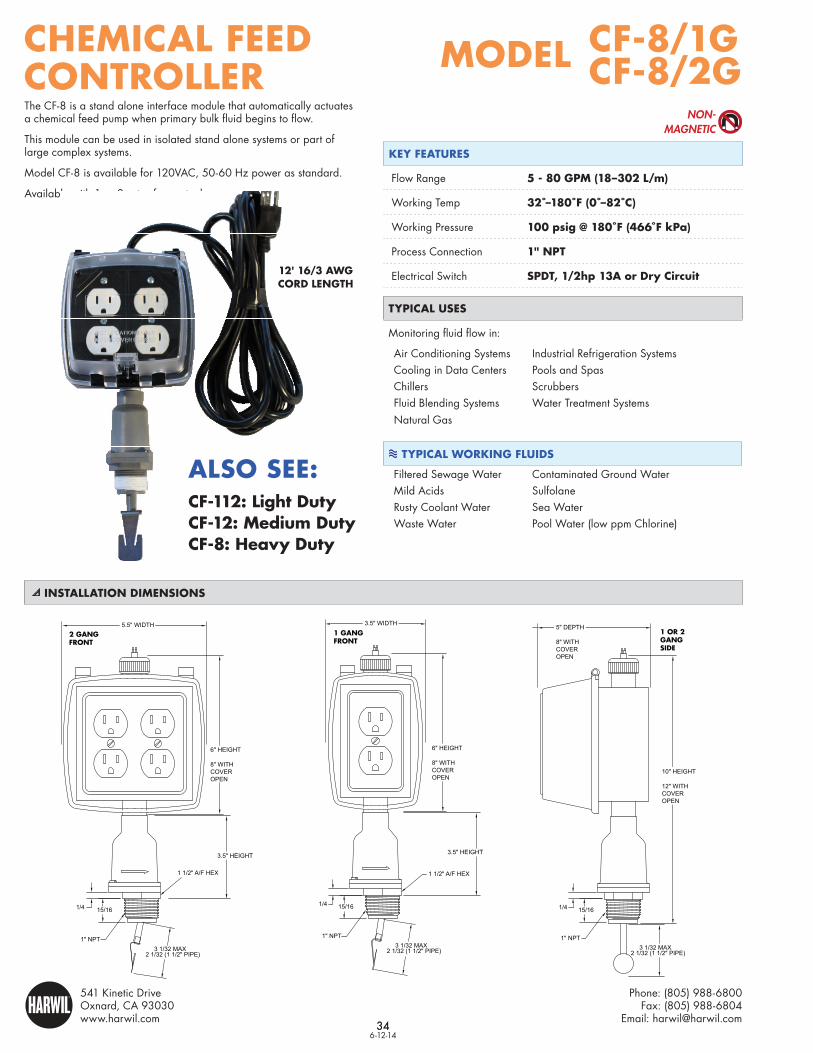
34 CHEMICAL FEED CONTROLLER 6-12-14 CF-8/1G CF-8/2G MODEL 34 Phone: (805) 988-6800 Fax: (805) 988-6804 Email: [email protected] 541 Kinetic Drive Oxnard, CA 93030 www.harwil.com HARWIL ® INSTALLATION DIMENSIONS TYPICAL USES Monitoring fluid flow in: Air Conditioning Systems Industrial Refrigeration Systems Cooling in Data Centers Pools and Spas Chillers Scrubbers Fluid Blending Systems Water Treatment Systems Natural Gas KEY FEATURES Flow Range 5 - 80 GPM (18–302 L/m) Working Temp 32˚–180˚F (0˚–82˚C) Working Pressure 100 psig @ 180˚F (466˚F kPa) Process Connection 1" NPT Electrical Switch SPDT, 1/2hp 13A or Dry Circuit TYPICAL WORKING FLUIDS Filtered Sewage Water Contaminated Ground Water Mild Acids Sulfolane Rusty Coolant Water Sea Water Waste Water Pool Water (low ppm Chlorine) NON- MAGNETIC The CF-8 is a stand alone interface module that automatically actuates a chemical feed pump when primary bulk fluid begins to flow. This module can be used in isolated stand alone systems or part of large complex systems. Model CF-8 is available for 120VAC, 50-60 Hz power as standard. Available with 1 or 2 sets of receptacles. 12' 16/3 AWG CORD LENGTH 15/16 1/4 1" NPT 2 1/32 (1 1/2" PIPE) 3 1/32 MAX 10" HEIGHT 12" WITH COVER OPEN 5" DEPTH 8" WITH COVER OPEN 6" HEIGHT 8" WITH COVER OPEN 5.5" WIDTH 3.5" HEIGHT 15/16 1/4 1 1/2" A/F HEX 2 1/32 (1 1/2" PIPE) 3 1/32 MAX 1" NPT 15/16 1/4 1 1/2" A/F HEX 2 1/32 (1 1/2" PIPE) 3 1/32 MAX 1" NPT 6" HEIGHT 8" WITH COVER OPEN 3.5" WIDTH 3.5" HEIGHT 2 GANG FRONT 1 GANG FRONT 1 OR 2 GANG SIDE CF-112: Light Duty CF-12: Medium Duty CF-8: Heavy Duty ALSO SEE: