P/N 315-085063-20 Siemens Building Technologies, Inc. 8 Fernwood Road Florham Park, New Jersey 07932 Siemens Building Technologies, Ltd. 2 Kenview Boulevard Brampton, Ontario L6T 5E4 CN Fire Safety MODEL MODEL MODEL MODEL MODEL CP CP CP CP CP-35 C -35 C -35 C -35 C -35 CON ON ON ON ONTR TR TR TR TROL OL OL OL OL P P P P PANEL ANEL ANEL ANEL ANEL INS INS INS INS INSTALLA ALLA ALLA ALLA ALLATION TION TION TION TION AND MAINTENANCE MANU AND MAINTENANCE MANU AND MAINTENANCE MANU AND MAINTENANCE MANU AND MAINTENANCE MANUAL AL AL AL AL Technical Manuals Online! - http://www.tech-man.com
Transcript
P/N 315-085063-20
Siemens Building Technologies, Inc.8 Fernwood RoadFlorham Park, New Jersey 07932
Siemens Building Technologies, Ltd.2 Kenview BoulevardBrampton, Ontario L6T 5E4 CN
Fire Safety
MODELMODELMODELMODELMODEL CP CP CP CP CP-35 C-35 C-35 C-35 C-35 CONONONONONTRTRTRTRTROLOLOLOLOL P P P P PANELANELANELANELANELINSINSINSINSINSTTTTTALLAALLAALLAALLAALLATION TION TION TION TION AND MAINTENANCE MANUAND MAINTENANCE MANUAND MAINTENANCE MANUAND MAINTENANCE MANUAND MAINTENANCE MANUALALALALAL
1. Earth ground the System 3 enclosureproperly; see the latest edition ofthe National Electrical Code forapproved methods. Conduit groundis NOT adequate.
2. Separate all wiring for initiatingdevices (i.e., detectors, manualstations, etc.) from all other wiring inthe System 3 enclosure.
3. INSULATE ALL CABLE DRAIN WIRESfrom any conduit or other earthgrounded electrical box, includingthose in the System 3 enclosure.
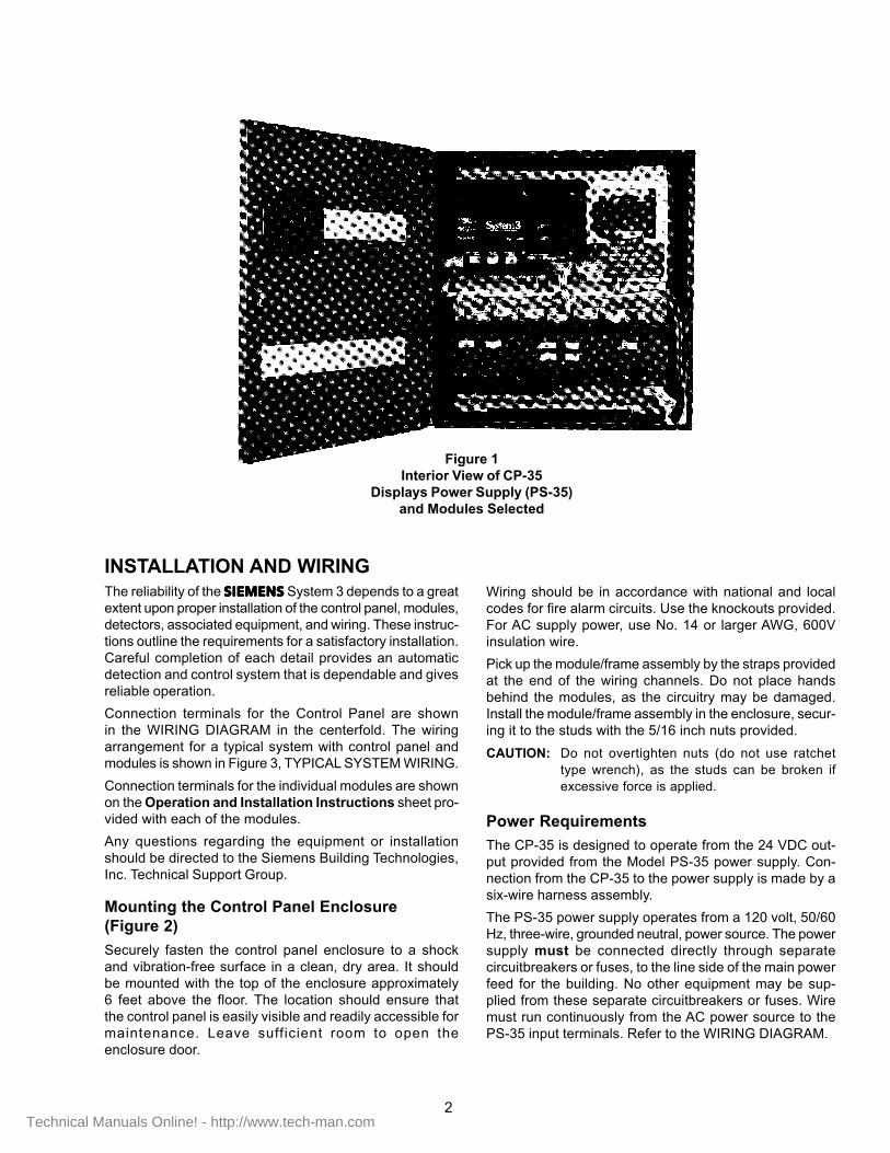
INSTALLATION AND WIRINGThe reliability of the SIEMENSSIEMENSSIEMENSSIEMENSSIEMENS System 3 depends to a greatextent upon proper installation of the control panel, modules,detectors, associated equipment, and wiring. These instruc-tions outline the requirements for a satisfactory installation.Careful completion of each detail provides an automaticdetection and control system that is dependable and givesreliable operation.
Connection terminals for the Control Panel are shownin the WIRING DIAGRAM in the centerfold. The wiringarrangement for a typical system with control panel andmodules is shown in Figure 3, TYPICAL SYSTEM WIRING.
Connection terminals for the individual modules are shownon the Operation and Installation Instructions sheet pro-vided with each of the modules.
Any questions regarding the equipment or installationshould be directed to the Siemens Building Technologies,Inc. Technical Support Group.
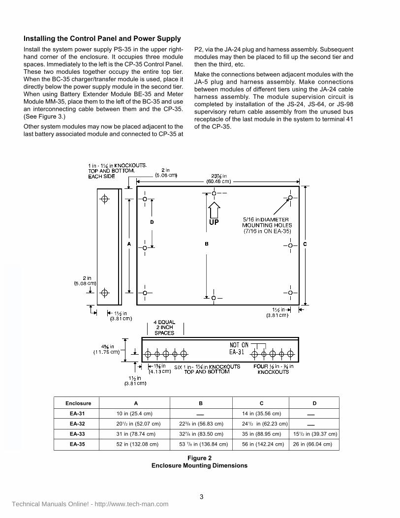
Mounting the Control Panel Enclosure(Figure 2)
Securely fasten the control panel enclosure to a shockand vibration-free surface in a clean, dry area. It shouldbe mounted with the top of the enclosure approximately6 feet above the floor. The location should ensure thatthe control panel is easily visible and readily accessible formaintenance. Leave sufficient room to open theenclosure door.
Wiring should be in accordance with national and localcodes for fire alarm circuits. Use the knockouts provided.For AC supply power, use No. 14 or larger AWG, 600Vinsulation wire.
Pick up the module/frame assembly by the straps providedat the end of the wiring channels. Do not place handsbehind the modules, as the circuitry may be damaged.Install the module/frame assembly in the enclosure, secur-ing it to the studs with the 5/16 inch nuts provided.
CAUTION: Do not overtighten nuts (do not use ratchettype wrench), as the studs can be broken ifexcessive force is applied.
Power Requirements
The CP-35 is designed to operate from the 24 VDC out-put provided from the Model PS-35 power supply. Con-nection from the CP-35 to the power supply is made by asix-wire harness assembly.
The PS-35 power supply operates from a 120 volt, 50/60Hz, three-wire, grounded neutral, power source. The powersupply must be connected directly through separatecircuitbreakers or fuses, to the line side of the main powerfeed for the building. No other equipment may be sup-plied from these separate circuitbreakers or fuses. Wiremust run continuously from the AC power source to thePS-35 input terminals. Refer to the WIRING DIAGRAM.
Install the system power supply PS-35 in the upper right-hand corner of the enclosure. It occupies three modulespaces. Immediately to the left is the CP-35 Control Panel.These two modules together occupy the entire top tier.When the BC-35 charger/transfer module is used, place itdirectly below the power supply module in the second tier.When using Battery Extender Module BE-35 and MeterModule MM-35, place them to the left of the BC-35 and usean interconnecting cable between them and the CP-35.(See Figure 3.)
Other system modules may now be placed adjacent to thelast battery associated module and connected to CP-35 at
P2, via the JA-24 plug and harness assembly. Subsequentmodules may then be placed to fill up the second tier andthen the third, etc.
Make the connections between adjacent modules with theJA-5 plug and harness assembly. Make connectionsbetween modules of different tiers using the JA-24 cableharness assembly. The module supervision circuit iscompleted by installation of the JS-24, JS-64, or JS-98supervisory return cable assembly from the unused busreceptacle of the last module in the system to terminal 41of the CP-35.
Figure 2Enclosure Mounting Dimensions
3
Enclosure A B C D
EA-31 10 in (25.4 cm) 14 in (35.56 cm)
EA-32 201/2 in (52.07 cm) 223/8 in (56.83 cm) 241/2 in (62.23 cm)
EA-33 31 in (78.74 cm) 327/8 in (83.50 cm) 35 in (88.95 cm) 151/2 in (39.37 cm)
EA-35 52 in (132.08 cm) 53 7/8 in (136.84 cm) 56 in (142.24 cm) 26 in (66.04 cm)
Where local installation codes require an outlet box, see the appro-priate Installation Instructions for the correct box to use with thatdevice. Where local codes permit, the detectors may be wiredusing limited-energy shielded cable.
The Control Panel enclosure and all detector and alarm circuitconduit must be properly grounded. Insure that all conduit makesgood electrical contact between the control panel and outlet boxes.Use ground shielded cable at the control panel only.
Detection/Alarm Initiating Circuit Wiringto Zone Modules
1. ALL WIRING MUST COMPLY WITH LOCAL ANDNATIONAL CODES.
2. FOR INITIATING DEVICE CIRCUITS:
a. All initiating circuits are rated power limited and should bewired in accordance with applicable codes.
b. The minimum wire size permitted is 18 AWG.
c. All wiring should be in a continuously grounded conduitor, where permissible, in approved 300V shielded, limitedenergy cable (such as Model LEC).
d. When shielded cable is used without conduit, terminatethe wiring shields at each device box, junction box,enclosure, etc. However, if the device box is alreadygrounded by another means, such as being mounted to agrounded structure, the wire shields should be continuousand should not be attached to the box in question. Thewire shields in all cases should be continuous andgrounded at the point of origin�at the control panel, forexample.
e. Multiple initiating circuits within the same cable or conduitdo not have to be individually shielded.
f. The maximum line resistance of a Class B circuit(both wires) is 36 ohms for standard initiating circuits and20 ohms if at least one detector has a relay.When using 4 wire, Class A supervised initiating cir-cuits, the total zone initiating circuit resistancemust be no more than 36 ohms�9 ohms per line. Fordetectors with relays, a total of 20 ohms is allowed. Forwire resistance information, refer to the latest edition ofthe National Electric Code, or contact the manufacturer ofthe wire in question.
g. T-tapping and parallel branching are not allowed oninitiating circuits. Every base, except the last one, will haveone set of incoming and one set of outgoing wires.
h. The wire interconnecting the devices is continuously su-pervised, and when the ZU-35 type modules are used,must be terminated with an EOL device (50µfd capacitorfurnished with the Control Panel). The EOL device may bemounted directly in Series 3 or Series 4 bases. When largebase units are used as the last detector on the zone cir-cuit, mount the EOL device to an EL-30/31 EOL devicemounting assembly. Be sure to observe polarity whenconnecting the EOL device (Refer to the label on the
EL-30). If the EOL device is installed incorrectly, thezone circuit may indicate a constant alarm condition.
NOTE: For four-wire Class A type connection, theend of line device is installed at the module(See Figure 3).
j. Some alarm initiating devices such as manual sta-tions, waterflow switches, and thermal units do nothave separate mounting bases. Connections to thesedevices are made directly to their internal screw ter-minals, based on their individual configuration.
Installing Detector Bases
Remove the Siemens Building Technologies, Inc. detectorbase from the carton. On the DB-4 detector base, a card-board cover holds the contacts between terminals 4 and 5together. This cover must be in place to test the circuit.
The DB-3S base provides a jumper only, connectedbetween terminals 1a and 1b of the base.
Install detector bases and other alarm initiating devices inaccordance with the wiring diagram. DO NOT install basesfor any detectors in direct air flow of air conditioning or ven-tilating air ducts.
Mount the EOL device at the last base in each detectorcircuit, as indicated on the Wiring Diagram (Refer to Detec-tion/Alarm Initiating Circuit Wiring above). Connect manualstations, thermal detectors, and all detector basesto the circuit at this time. Refer to the Wiring Diagram of thespecific equipment for connection details.
Installation of Audible Alarm Devices
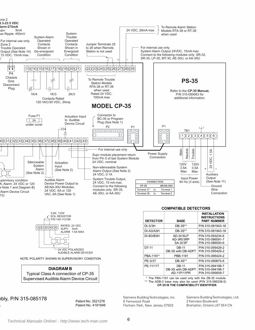
All audible alarm device circuits are supervised and usepolarized alarm devices. Other types of devices do not func-tion properly on these circuits. For proper circuit supervision,terminate the circuit with a 5.6K ohm end-of-line resistor.When a DC alarm circuit is used, the EOL device is a 5.6K, 1/2W resistor (furnished with the CP-35). This resistor may bemounted in an EL-30/31 mounting assembly. If an AC alarmcircuit is used, the EOL device must be a 5.6K, 5W resistor(with the EL-32 assembly).
NOTE: The above applies when AE-30U type AlarmExtender modules are used. Class A audible alarmconnections must operate from 24 VDC, and theEOL device is connected at the module terminals.
FOR INDICATING APPLIANCE CIRCUITS:
1. All releasing and extinguishing circuits must use a min-imum of 16 AWG wire, shielded cable, or must be incontinuously grounded conduit. The maximum lineresistance (both wires) permitted is 3 ohms. These circuitsincluding their wiring, are not power limited and should bewired in accordance with applicable codes. For wireresistance information, refer to the latest edition of the
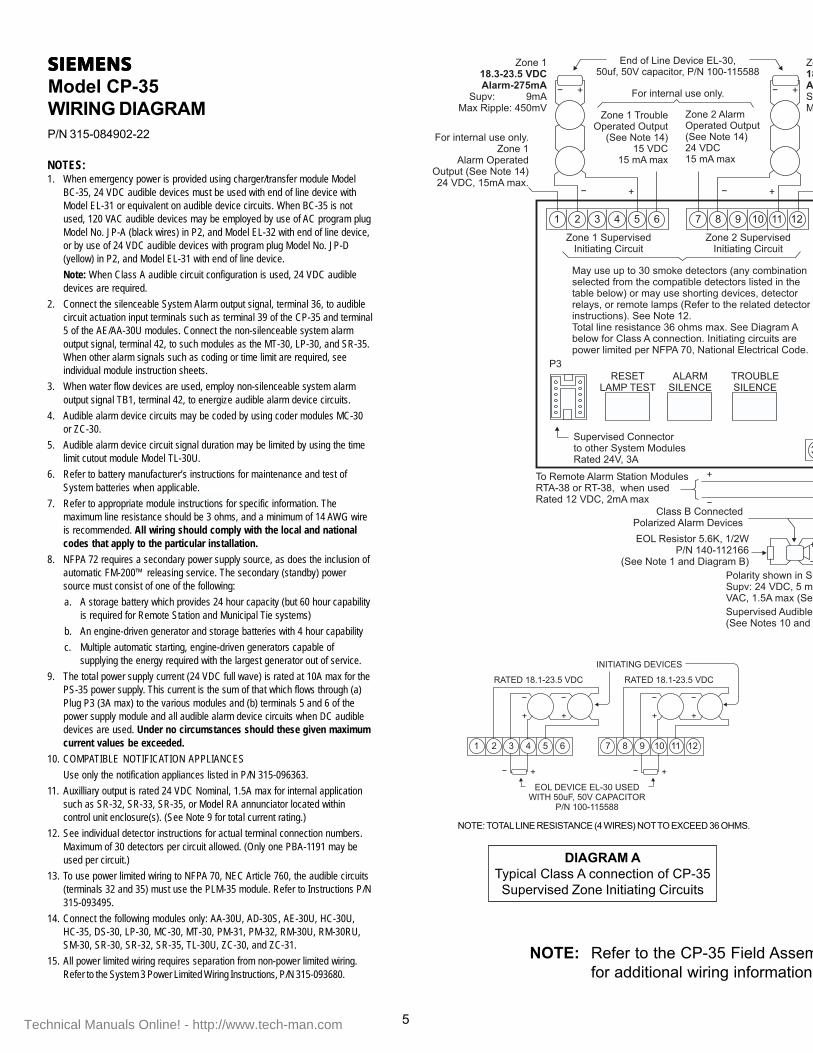
NOTES:1. When emergency power is provided using charger/transfer module Model
BC-35, 24 VDC audible devices must be used with end of line device withModel EL-31 or equivalent on audible device circuits. When BC-35 is notused, 120 VAC audible devices may be employed by use of AC program plugModel No. JP-A (black wires) in P2, and Model EL-32 with end of line device,or by use of 24 VDC audible devices with program plug Model No. JP-D(yellow) in P2, and Model EL-31 with end of line device.
Note: When Class A audible circuit configuration is used, 24 VDC audibledevices are required.
2. Connect the silenceable System Alarm output signal, terminal 36, to audiblecircuit actuation input terminals such as terminal 39 of the CP-35 and terminal5 of the AE/AA-30U modules. Connect the non-silenceable system alarmoutput signal, terminal 42, to such modules as the MT-30, LP-30, and SR-35.When other alarm signals such as coding or time limit are required, seeindividual module instruction sheets.
3. When water flow devices are used, employ non-silenceable system alarmoutput signal TB1, terminal 42, to energize audible alarm device circuits.
4. Audible alarm device circuits may be coded by using coder modules MC-30or ZC-30.
5. Audible alarm device circuit signal duration may be limited by using the timelimit cutout module Model TL-30U.
6. Refer to battery manufacturer’s instructions for maintenance and test ofSystem batteries when applicable.
7. Refer to appropriate module instructions for specific information. Themaximum line resistance should be 3 ohms, and a minimum of 14 AWG wireis recommended. All wiring should comply with the local and nationalcodes that apply to the particular installation.
8. NFPA 72 requires a secondary power supply source, as does the inclusion ofautomatic FM-200™ releasing service. The secondary (standby) powersource must consist of one of the following:
a. A storage battery which provides 24 hour capacity (but 60 hour capabilityis required for Remote Station and Municipal Tie systems)
b. An engine-driven generator and storage batteries with 4 hour capability
c. Multiple automatic starting, engine-driven generators capable ofsupplying the energy required with the largest generator out of service.
9. The total power supply current (24 VDC full wave) is rated at 10A max for thePS-35 power supply. This current is the sum of that which flows through (a)Plug P3 (3A max) to the various modules and (b) terminals 5 and 6 of thepower supply module and all audible alarm device circuits when DC audibledevices are used. Under no circumstances should these given maximumcurrent values be exceeded.
10. COMPATIBLE NOTIFICATION APPLIANCES
Use only the notification appliances listed in P/N 315-096363.
11. Auxilliary output is rated 24 VDC Nominal, 1.5A max for internal applicationsuch as SR-32, SR-33, SR-35, or Model RA annunciator located withincontrol unit enclosure(s). (See Note 9 for total current rating.)
12. See individual detector instructions for actual terminal connection numbers.Maximum of 30 detectors per circuit allowed. (Only one PBA-1191 may beused per circuit.)
13. To use power limited wiring to NFPA 70, NEC Article 760, the audible circuits(terminals 32 and 35) must use the PLM-35 module. Refer to Instructions P/N315-093495.
14. Connect the following modules only: AA-30U, AD-30S, AE-30U, HC-30U,HC-35, DS-30, LP-30, MC-30, MT-30, PM-31, PM-32, RM-30U, RM-30RU,SM-30, SR-30, SR-32, SR-35, TL-30U, ZC-30, and ZC-31.
15. All power limited wiring requires separation from non-power limited wiring.Refer to the System 3 Power Limited Wiring Instructions, P/N 315-093680.
National Electric Code, or contact the manufacturer ofthe wire in question.
2. All audible and visual alarm signalling circuits must usea minimum of 14 AWG wire. The maximum lineresistance (both wires) permitted is 3 ohms. The wiringdoes not have to be shielded. These circuits and theirwiring, are not power limited and should be wired inaccordance with applicable codes. For wire resistanceinformation, refer to the latest edition of the NationalElectrical Code, or contact the manufacturer of the wirein question.
3. T-tapping and parallel branching are not allowed oneither releasing or audible circuits.
4. On leased line circuits like those with SIEMENSSIEMENSSIEMENSSIEMENSSIEMENS ModelLP-30, the external wiring must be between 2K and 5Kohms. This line must be a dedicated pair for fire alarmuse only. For wire resistance information, contact themanufacturer/installer of the wire in question.
5. On municipal tie circuits like those with SIEMENSSIEMENSSIEMENSSIEMENSSIEMENS ModelMT-30, the total loop resistance from the LLM-1 to themunicipal tie, including the 14.5 ohms in the municipaltie, should not exceed 22.5 ohms. For wire resistanceinformation, refer to the latest edition of the NationalElectric Code, or contact the manufacturer of the wire inquestion.
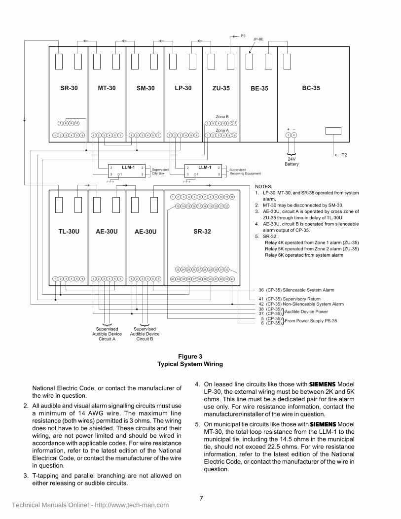
Figure 3Typical System Wiring
NOTES:1. LP-30, MT-30, and SR-35 operated from system
alarm.2. MT-30 may be disconnected by SM-30.3. AE-30U, circuit A is operated by cross zone of
ZU-35 through time-in delay of TL-30U.4. AE-30U, circuit B is operated from silenceable
alarm output of CP-35.5. SR-32:
Relay 4K operated from Zone 1 alarm (ZU-35)Relay 5K operated from Zone 2 alarm (ZU-35)Relay 6K operated from system alarm
Check that cardboard covers or jumpers, as applicable, are inplace. Install end-of-line device(s). Detector circuits should NOTbe connected to modules at this time. No plug-in detectorsshould be in their bases.
Check the detector/alarm initiating device circuit(s). Short thewires together (discharges EOL device). Using a VOM set toread high resistance (for example, a Simpson Model 260 set tothe Rx 10,000 ohm range), measure the resistance of the circuit.
NOTE: Observe polarity; connect positive side of meterto positive side of the circuit.
The meter needle should quickly drop down to a low resis-tance reading and then slowly increase in resistance to avalue greater than one megohm. If maximum resistance reachedis less than one megohm, check for reversed EOL device orEOL device with excessive leakage. Also check that the resis-tance between each side of the circuit and the enclosure orground is greater than 25K ohms.
If wiring reads correct resistance on meter, connect wires toproper terminals on Control Panel or module.
Remove all detector shield covers and/or jumpers, as applicable,and install plug-in detectors in their bases.
To Test System Operation
CAUTION:
If the System is connected to the Fire Department,or activates an external system (for example, a leased lineconnection), disarm the outputs before servicing to pre-vent activation. Notify persons in the building(s) that youare conducting a System test so that they can ignore anyalarms that sound during testing. Be sure to reset the Sys-tem at the end of the inspection.
a. Unlock and open system enclosure door.
b. Make certain that any and all unwanted outgoing alarmsignals are disconnected in the event that the Control Panelgoes into an alarm condition.
c. Apply required power, AC and battery, to system.
Only the power LED should be on. All disconnect and/or silenc-ing switches, if used, should be in their normal positions. MoveRESET/LAMP TEST switch to RESET and hold. All ControlPanel indicators, LEDs, and the trouble horn will operate. Re-lease RESET switch. The trouble LED and horn should returnto normal supervisory operation.
To test supervision of the audible alarm circuit(s), open eachcircuit at the EOL device. Check that trouble indications appearat the Control Panel. If proper indications appear, reconnectthe lead to return the system to normal supervisory operation.
To test operation of the audible alarm circuit(s), activate adetector/actuation device or manual station. Check that allaudible alarm devices sound, that the alarm lamp lights, andthat the audible devices can be silenced. See Note 1 below.
To test operation of detection/actuation circuit(s), activateeach device and manual station. Check that the detectoralarm LED lights and that alarm and zone indications aregiven by the Control Panel and the proper module. To acti-vate a detector (ion or photoelectric) or to test for GO/NOGO operation, use SIEMENSSIEMENSSIEMENSSIEMENSSIEMENS Test Gas, P/N 315-282747.Activate a thermal detector by using an electric heat gun(See NFPA 72 Detectors). Refer to the detector Installationand Wiring Instructions for more testing information.
Use disconnect switches (See Note 2) during tests toisolate any external alarm operated circuits (activation of fireextinguishing system, notification to Fire Department, etc.).When such external circuits are connected to the system,check that upon alarm, they operate when switch is in itsnormal position and that they do not operate when the switchis in the disconnect position.
If the above tests provide proper results, close and lockthe enclosure door. If not, refer to MAINTENANCE.
NOTES:1. When activated from silenceable alarm output terminal.2. When this feature is used in system.
MAINTENANCE
To insure proper and reliable operation, follow thisinspection and testing schedule.
Every 6 Months
Inspect all detectors for accumulations of dirt and dust.Clean detectors as necessary by following the CleaningProcedure outlined in the Installation and Wiring Instruc-tions for each detector. Gear cleaning program intervals tothe individual detector environment.
Testing the System
Test the system to insure its operational reliability and opti-mum performance. Only qualified service personnel shouldtest. Test as frequently as, and in accordance with, NFPA72 Signaling Systems and 72 Detectors.
CAUTION:
If the System is connected to the Fire Department,or activates an external system (for example, a leasedline connection), disarm the outputs before servic-ing to prevent activation. Notify persons in thebuilding(s) that you are conducting a System test sothat they can ignore any alarms that sound duringtesting. Be sure to reset the System at the end of theinspection.
Activate a detector or other alarm initiating device. To acti-vate a detector (ion or photoelectric) or to test for GO/NOGO operation, use SIEMENSSIEMENSSIEMENSSIEMENSSIEMENS Test Gas, P/N 315-282747.
Activate a thermal detector by usingan electric heat gun(See NFPA 72 Detectors). Refer tothe detector Installationand Wiring Instructions for moretesting information.
Check the operation of each detector/alarm initiatingdevice on all circuits. Measure the sensitivity of each de-tector using the appropriate sensitivity tester (where ap-plicable).
Check that all audibles sound, that the System alarmLED lights, and that the audible devices can besilenced. Check that the proper zone lamp responds.
Reset the System. Check that the System LEDs andaudibles activate when the Reset switch is movedmomentarily to the RESET position.
After completing the test, return all switches to Normalposition.
TROUBLESHOOTING THE CP-35A system trouble condition may result from any of the fol-lowing conditions.
1. Module placement loop open
a. Check for 24 VDC with respect to system common(terminal 6 of the power supply) at terminal 41 ofthe CP-35.
b. With no voltage present at terminal 41, check thatall modules are in place and that the ten wire cableconnectors are both present and well seated oneach module connector.
2. Trouble condition from a supervised zone, audiblealarm, or associated module from which a troublesignal may be produced
a. Observe visual trouble indication on individualmodules.
b. If present, proceed to correct that individual faultcondition.
3. Ground fault connection
a. Observe that the visual ground fault indicator is lit.
b. Normal voltage between chassis ground and systemcommon (terminal 6 of power supply) should readapproximately 7.5 to 8 VDC.
c. A higher voltage reading indicates a ground withrespect to the positive voltage supply source.
d. A lower voltage reading indicates a ground withrespect to the common or minus voltage supplysource.
4. Auxiliary power output terminals (5 and 6) of the powersupply not energized
a. Normal voltage value should be the supply voltagevalue (approximately 24 VDC).
b. With no voltage present, check fuse 3 of the powersupply.
5. Loss of 120 VAC trouble supply input to the powersupply (terminals 3 and 2 of the power supply)
a. Check incoming supply voltage.
b. With voltage present at terminals 3 and 2 of powersupply, read voltage at P1, pin 5 with respect toterminal 2. With no voltage reading (120 VAC) pres-ent, check F1 fuse within the power supply unit.
6. Loss of 120 VAC main supply input to power supply(terminals 1 and 2 of power supply). (When emergencypower is provided with the BC-35, the CP-35 ControlPanel power indicator flashes repeatedly.) When noemergency power is provided, all visual indicators areturned off and only a change of state of trouble relay2K/4 results.
a. Check incoming supply voltage.
b. With voltage present at terminals 1 and 2 of thepower supply, check circuitbreaker CB1 bydepressing the reset button and/or F2 fuse withinthe power supply unit.
a. Observe visual trouble indication on the BC-35module.
b. See individual BC-35 Installation Instructions forpossible trouble conditions.
8. Key operated remote alarm station (RA-38/RTA-38,when used) silence switch not in normal open con-dition (Includes possible low resistance value betweenoutgoing lines, terminals 30 and 31 of the CP-35).
a. Normal reading should be 11.5 to 12 VDC.
b. For lower voltage value readings, check station orlines for possible shunted condition.
9. Loss of 12 VDC logic supply
a. With terminals 30 and 31 of the CP-35 open,measure 11.5 to 12 VDC across these terminals.
b. With no low voltage present at terminals 30 and 31of the CP-35, check that interconnecting pin 34connection between the main PC board and thesecondary PC board of the CP-35 is securelyin place.
NOTE: Make certain that plug connection is re-placed in the correct pin to pin sequence.(Arrow marking on the plug connectionsgoing to pin 1.)
10. Supervision of alarm relay coil (1K/4) open circuits.
Operation of the relay by placing the Control Panel inalarm condition indicates that coil winding is intact.(Before placing panel in alarm condition, makecertain that any, and all, unwanted outgoing alarmsignal connections are disconnected.)