31
MODEL “D” FRE-HEATER ® INSTALLATION AND OPERATION MANUAL Part No. 8800430 Effective March 1, 1993 Revised April 12, 2011 ® ® THE MILK COOLING SYSTEMS SPECIALISTS ™
MODEL “D” FRE-HEATER®
INSTALLATION AND OPERATION MANUAL
Part No. 8800430
Effective March 1, 1993Revised April 12, 2011
8820261
®
®
THE MILK COOLING SYSTEMS SPECIALISTS™

Section 1.0 - Introduction1.1 Description of the System . . . . . . . . . . . . . . . . . . . . . . . . . . . . . . . . . . . . . . . . . . . . . . . . . . . . . . . . . .1
1.2 Capacity . . . . . . . . . . . . . . . . . . . . . . . . . . . . . . . . . . . . . . . . . . . . . . . . . . . . . . . . . . . . . . . . . . . . . . .1
Table 1—Model “D” Technical Specifications . . . . . . . . . . . . . . . . . . . . . . . . . . . . . . . . . . . . . . . . . . . .2
1.3 Fre-Heater Location . . . . . . . . . . . . . . . . . . . . . . . . . . . . . . . . . . . . . . . . . . . . . . . . . . . . . . . . . . . . . . .2
1.4 Leveling . . . . . . . . . . . . . . . . . . . . . . . . . . . . . . . . . . . . . . . . . . . . . . . . . . . . . . . . . . . . . . . . . . . . . . .3
Figure 1—50-Gallon Model “D” Fre-Heater 3/4" Water Connection Tank . . . . . . . . . . . . . . . . . . . . . . . . .3
Figure 2—80-Gallon Model “D” Fre-Heater 3/4" Water Connection Tank . . . . . . . . . . . . . . . . . . . . . . . . .3
Figure 3—119-Gallon Model “D” Fre-Heater 11/2" Water Connection Tank . . . . . . . . . . . . . . . . . . . . . . .3
Figure 4—Top Head Layout: Water Connections, Anode Locations, and Refrigerant Piping . . . . . . . . . . .4
Section 2.0 - Installation 2.1 Installing Water Piping . . . . . . . . . . . . . . . . . . . . . . . . . . . . . . . . . . . . . . . . . . . . . . . . . . . . . . . . . . . . .5
Figure 5—Typical Hot Water Dump Valve Piping . . . . . . . . . . . . . . . . . . . . . . . . . . . . . . . . . . . . . . . . .6
Figure 6—Typical Plumbing for Fre-Heater Water Connection . . . . . . . . . . . . . . . . . . . . . . . . . . . . . . . .7
Figure 7—Typical Multiple-Unit Series Plumbing for Fre-Heaters (Commercial Application) . . . . . . . . . .7
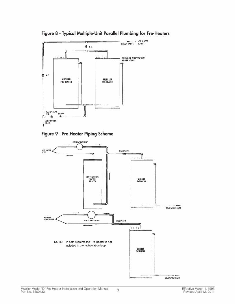
Figure 8—Typical Multiple-Unit Parallel Plumbing for Fre-Heaters . . . . . . . . . . . . . . . . . . . . . . . . . . . . .8
Figure 9—Fre-Heater Piping Scheme . . . . . . . . . . . . . . . . . . . . . . . . . . . . . . . . . . . . . . . . . . . . . . . . . .8
2.2 Refrigeration Connections . . . . . . . . . . . . . . . . . . . . . . . . . . . . . . . . . . . . . . . . . . . . . . . . . . . . . . . . . .9
2.3 Heat Pumps . . . . . . . . . . . . . . . . . . . . . . . . . . . . . . . . . . . . . . . . . . . . . . . . . . . . . . . . . . . . . . . . . . . .11
2.4 Ice Machines . . . . . . . . . . . . . . . . . . . . . . . . . . . . . . . . . . . . . . . . . . . . . . . . . . . . . . . . . . . . . . . . . . .11
2.5 Refrigerant Charge . . . . . . . . . . . . . . . . . . . . . . . . . . . . . . . . . . . . . . . . . . . . . . . . . . . . . . . . . . . . . . .11
2.6 Test Run . . . . . . . . . . . . . . . . . . . . . . . . . . . . . . . . . . . . . . . . . . . . . . . . . . . . . . . . . . . . . . . . . . . . . .11
Figure 10—Typical Refrigeration Connections for Single Refrigeration Unit and Single-Circuit Piping . . .12
Figure 11—Typical Single Refrigeration Unit with Multiple-Circuit Piping . . . . . . . . . . . . . . . . . . . . . . .12
Figure 12—Typical Dual Refrigeration Unit Piping . . . . . . . . . . . . . . . . . . . . . . . . . . . . . . . . . . . . . . . .13
Figure 13—Fre-Heater Location with Hot Gas Defrost Valve, Oil Separator, and/or Discharge
Muffler in System . . . . . . . . . . . . . . . . . . . . . . . . . . . . . . . . . . . . . . . . . . . . . . . . . . . . . . . . . . . . .13
Figure 14—Typical Heat Pump Refrigerant Piping Diagram . . . . . . . . . . . . . . . . . . . . . . . . . . . . . . . . .14
2.7 Electrical Connections for Model “DE” Fre-Heater . . . . . . . . . . . . . . . . . . . . . . . . . . . . . . . . . . . . . . . .14
2.8 Special Model “DE” Operating Instructions . . . . . . . . . . . . . . . . . . . . . . . . . . . . . . . . . . . . . . . . . . . . .15
2.9 Maintenance . . . . . . . . . . . . . . . . . . . . . . . . . . . . . . . . . . . . . . . . . . . . . . . . . . . . . . . . . . . . . . . . . . .15
Figure 15—Model “DE” Wiring Diagram . . . . . . . . . . . . . . . . . . . . . . . . . . . . . . . . . . . . . . . . . . . . . . .16
Section 3.0 - Instructions for Water Temperature and 3-Way Heat Reclaim Valve (for Refrigerant), Part No. 8804796
3.1 Solenoid Valve Installation . . . . . . . . . . . . . . . . . . . . . . . . . . . . . . . . . . . . . . . . . . . . . . . . . . . . . . . . .17
Table 2—Three-Way Heat Reclaim Valves for Refrigerants 22 and 502 . . . . . . . . . . . . . . . . . . . . . . . . .17
Figure 16—Three-Way Heat Reclaim Valves . . . . . . . . . . . . . . . . . . . . . . . . . . . . . . . . . . . . . . . . . . . .17
Figure 17—Suggested Refrigeration Piping of Valve for Typical Model “D” and
“DE” Fre-Heater System . . . . . . . . . . . . . . . . . . . . . . . . . . . . . . . . . . . . . . . . . . . . . . . . . . . . . . . .18
MODEL “D” FRE-HEATER®
INSTALLATION AND OPERATION MANUAL
®
Table of Contents

Table of Contents
Section 3.0 - Instructions for Water Temperature and 3-Way Heat Reclaim Valve (for Refrigerant), Part No. 8804796 (Continued)
3.2 Aquastat Installation . . . . . . . . . . . . . . . . . . . . . . . . . . . . . . . . . . . . . . . . . . . . . . . . . . . . . . . . . . . . . .18
Figure 18—Suggested Aquastat Piping . . . . . . . . . . . . . . . . . . . . . . . . . . . . . . . . . . . . . . . . . . . . . . . .18
3.3 Electrical Installation . . . . . . . . . . . . . . . . . . . . . . . . . . . . . . . . . . . . . . . . . . . . . . . . . . . . . . . . . . . . .19
Figure 19—Wiring of Electrical Components . . . . . . . . . . . . . . . . . . . . . . . . . . . . . . . . . . . . . . . . . . . .19
3.4 Checkout and Test Run . . . . . . . . . . . . . . . . . . . . . . . . . . . . . . . . . . . . . . . . . . . . . . . . . . . . . . . . . . .19
Figure 20—Three-Way Heat Reclaim Valve Dimensions . . . . . . . . . . . . . . . . . . . . . . . . . . . . . . . . . . . .20
Table 3—Dimensions Chart . . . . . . . . . . . . . . . . . . . . . . . . . . . . . . . . . . . . . . . . . . . . . . . . . . . . . . . .20
Table 4—Discharge Check Valve Sizing . . . . . . . . . . . . . . . . . . . . . . . . . . . . . . . . . . . . . . . . . . . . . . .20
Table 5—Capacity (Tons) Chart for Valve Ports . . . . . . . . . . . . . . . . . . . . . . . . . . . . . . . . . . . . . . . . . .21
Section 4.0 - Btuh Estimated Capacity 4.1 Btuh Estimated Capacity . . . . . . . . . . . . . . . . . . . . . . . . . . . . . . . . . . . . . . . . . . . . . . . . . . . . . . . . . . .22
Table 6—Model “D” Fre-Heater Estimated Per Circuit Btuh Recovery . . . . . . . . . . . . . . . . . . . . . . . . . .22
Section 5.0 - Fre-Heater Equipment Markings5.1 Label No. 8805299, Warning Label - R-22 . . . . . . . . . . . . . . . . . . . . . . . . . . . . . . . . . . . . . . . . . . . . . .23
5.2 Label No. 8801149, Warning Label - Disconnecting Power . . . . . . . . . . . . . . . . . . . . . . . . . . . . . . . . . .23
5.3 Label No. 8802732, Warning Label - Pressure Relief . . . . . . . . . . . . . . . . . . . . . . . . . . . . . . . . . . . . . . .23
5.4 Label No. 8800996, Copper Conductor . . . . . . . . . . . . . . . . . . . . . . . . . . . . . . . . . . . . . . . . . . . . . . . .23
5.5 Label No. 8801888, Warning Label - Hot Water . . . . . . . . . . . . . . . . . . . . . . . . . . . . . . . . . . . . . . . . . .24
5.6 Label No. 3791, Hot . . . . . . . . . . . . . . . . . . . . . . . . . . . . . . . . . . . . . . . . . . . . . . . . . . . . . . . . . . . . .24
5.7 Label No. 3792, Cold . . . . . . . . . . . . . . . . . . . . . . . . . . . . . . . . . . . . . . . . . . . . . . . . . . . . . . . . . . . . .24
5.8 Label No. 8802896, CSA . . . . . . . . . . . . . . . . . . . . . . . . . . . . . . . . . . . . . . . . . . . . . . . . . . . . . . . . . . .24
5.9 Label No. 8820623, Electrical Warning . . . . . . . . . . . . . . . . . . . . . . . . . . . . . . . . . . . . . . . . . . . . . . . . .24
5.10 Label No. 8800215, Pressure Relief . . . . . . . . . . . . . . . . . . . . . . . . . . . . . . . . . . . . . . . . . . . . . . . . . .24
5.11 Label No. 8801408, Attention . . . . . . . . . . . . . . . . . . . . . . . . . . . . . . . . . . . . . . . . . . . . . . . . . . . . . .25
5.12 Label No. 8803611, Fre-Heater Model “DE” Data Plate . . . . . . . . . . . . . . . . . . . . . . . . . . . . . . . . . . . . .25
5.13 Label No. 31433, Fre-Heater Model “D” Data Plate . . . . . . . . . . . . . . . . . . . . . . . . . . . . . . . . . . . . . . .25
5.14 Label No. 31246, Fre-Heater Name Plate . . . . . . . . . . . . . . . . . . . . . . . . . . . . . . . . . . . . . . . . . . . . . . .25
5.15 Label No. 8820454, Important! Dry Nitrogen Gas . . . . . . . . . . . . . . . . . . . . . . . . . . . . . . . . . . . . . . . . .26
5.16 Label No. 8823999, Attention . . . . . . . . . . . . . . . . . . . . . . . . . . . . . . . . . . . . . . . . . . . . . . . . . . . . . . .26
5.17 Label No. 9901403, In . . . . . . . . . . . . . . . . . . . . . . . . . . . . . . . . . . . . . . . . . . . . . . . . . . . . . . . . . . .26
5.18 Label No. 9901404, Out . . . . . . . . . . . . . . . . . . . . . . . . . . . . . . . . . . . . . . . . . . . . . . . . . . . . . . . . . .26
5.19 Label No. 30397, Stainless Steel . . . . . . . . . . . . . . . . . . . . . . . . . . . . . . . . . . . . . . . . . . . . . . . . . . . . .26
5.20 Label No. 8824816, CRN . . . . . . . . . . . . . . . . . . . . . . . . . . . . . . . . . . . . . . . . . . . . . . . . . . . . . . . . . . .26
Section 6.0 - Appendix A6.1 Model “D” Fre-Heater Thermal Expansion Tank Installation for Dairy Farm Applications . . . . . . . . . . .27
Figure 21—Thermal Expansion Tank Diagram . . . . . . . . . . . . . . . . . . . . . . . . . . . . . . . . . . . . . . . . . . . . . . .27

Mueller Model “D” Fre-Heater Installation and Operation Manual Effective March 1, 1993Part No. 8800430 Revised April 12, 2011
1
SECTION 1.0 - INTRODUCTION
1.1 Description of the System
The Mueller Model “D” Fre-Heater® is designed to recover heat removed by refrigeration or airconditioning systems. It is a de-superheater which removes most or all of the sensible heat from thecompressor’s hot discharged gas and uses the existing condenser to remove the remaining heat tocondense the refrigerant.
The Model “D” is a fully insulated, double-wall heat exchanger that can operate on any potable watersupply. It is CSA listed. All Model “D” water tanks are rated for 150 psi working pressure and are fittedwith two corrosion protection anodes. Refrigeration circuits are rated for a maximum working pressureof 426 psi.
All Model “DE-120” Fre-Heaters have one 240-vac single-phase, 4,500-watt electric element located inthe upper portion of the tank. The placement of this element allows the maximum utilization of therefrigerant heat recovery system and minimizes the usage of electricity in directly heating the water.(NOTE: An alternate 6,000-watt electric element is available.)
The outer jacket of all Model “D” Fre-Heaters is highly corrosion-resistant stainless steel and will remainbright and rust-free with a minimum of care. In coastal areas where the air contains a high salt content,the bright appearance of the Fre-Heater can be maintained by rubbing it with oil or a light grease assoon as it is installed. Abrasive cleaning materials or compounds should not be used on the outerjacket, as they will scratch the surface.
The Fre-Heater unit is not normally suitable for use on capillary tube refrigeration systems.
The Fre-Heater unit is not intended to and should not be used to replace the normal air- or water-cooledcondenser.
1.2 Capacity
The Model “D” Fre-Heater is designed for use with air- or water-cooled refrigeration units. The size ofthe units and refrigeration systems on which each model may be used are shown in Table 1.Dimensions of the various models of Model “D” Fre-Heater are shown in Figures 1 to 4.
The amount of hot water which can be generated by the Model “D” will vary, depending on runningtime and size of the refrigeration system.

Mueller Model “D” Fre-Heater Installation and Operation Manual Effective March 1, 1993Part No. 8800430 Revised April 12, 2011
Table 1 - Model “D” Technical Specifications
1 Nominal water tank capacity: D-50/50 U.S. gallons; D-80/80 U.S. gallons; and D-120/119 U.S. gallons.2 Refrigeration tonnage capacities are evaporator tons and not heat of rejection tons. Conditions for the capacities are: 30°F evaporator, 110°F condensing temperature, and 50°F discharge gas superheat. Pressuredrop through the Fre-Heater refrigeration circuit will be approximately 15 psi at the maximum tonnage application. Pressure dropat the mid-range tonnage will be approximately 5 to 7 psi. The highest percentage of heat recovered per ton is usually obtained ator below the mid-range of the refrigeration tonnage capacity.
3 “DE” models have one 4,500-watt, 240-volt electric element.4 Ammonia only.5Fre-Heaters are not rated for use with R-410A.
1.3 Fre-Heater Location
The Fre-Heater should be located inside. If it is necessary to locate the Fre-Heater outside, it must beunder a cover. The Fre-Heater must be protected from water dripping or spraying, or in any waycollecting on the top surface, as this can result in the failure of the heat exchanger.
When selecting a location for a Model “D” Fre-Heater, the ability of that location to bear the loadedweight of the Fre-Heater should be a prime consideration. The loaded weights of all Model “D” Fre-Heaters are listed in Table 1.
The Model “D” Fre-Heater must be protected from freezing. Particular attention should be directed toprotecting the water piping going to and from the Fre-Heater.
The Model “D” Fre-Heater should be located as near as practical to the refrigeration unit(s). The Fre-Heater should not be located where cooling tower or evaporative condenser water will be in continualdirect contact with the exterior surface. Careful planning of the Fre-Heater location and plumbing canreduce installation costs and save time during installation and on maintenance in the future.
For dimensions, see Figures 1, 2, 3, and 4. Adequate space must be provided between walls and theFre-Heater for convenient access to all piping connections. See suggested refrigerant piping diagramsshown in Figures 10, 11, and 12.
2
Water No. of Refrig. Per Circuit Refrig. Approx. Approx.Model Mueller Connection Refrig. Connection Application Shipping LoadedNo.1 Part No. Sizes Circuits Sizes Refrigerant5 Capacity2 Dimensions Wt. (lb) Wt. (lb)
D-50 8823750 3⁄4" MPT 1 5⁄8" ODM R-22 / R-507 .5 thru 4 Ht. 537⁄8" 220 600Dia. 213⁄4"
D2-50 8823751 3⁄4" MPT 2 5⁄8" ODM R-22 / R-507 .5 thru 4 Ht. 537⁄8" 220 600Dia. 213⁄4"
D-80 8823780 3⁄4" MPT 2 3⁄4" ODM R-22 / R-507 1 thru 5 Ht. 581⁄4" 300 940Dia. 251⁄4"
DE-1203 8823822 11⁄2" FPT 2 11⁄8" ODM R-22 / R-507 3 thru 15 Ht. 615⁄8" 430 1,300Dia. 291⁄2"
D-120 8823821 11⁄2" FPT 2 3⁄4" ODM R-22 / R-507 1 thru 7.5 Ht. 615⁄8" 430 1,300Dia. 291⁄2"
D2-120 8823820 11⁄2" FPT 2 11⁄8" ODM R-22 / R-507 3 thru 15 Ht. 615⁄8" 430 1,300Dia. 291⁄2"
DH-120 8823823 11⁄2" FPT 2 15⁄8" ODM R-22 / R-507 7 thru 35 Ht. 615⁄8" 430 1,300Dia. 291⁄2"
DA-1204 8823826 11⁄2" FPT 2 1" MPT R-717 5 thru 25 Ht. 615⁄8" 430 1,300Dia. 291⁄2"

Mueller Model “D” Fre-Heater Installation and Operation Manual Effective March 1, 1993Part No. 8800430 Revised April 12, 20113
1.4 Leveling
Three large cap screws are provided with the Model “D” to raise it above the floor and level it.
The cap screws should be screwed out enough to raise the tank slightly before setting it in place, thenadjusted as needed to level the unit. The legs provided will allow the Fre-Heater to be raisedapproximately 1". Should more height be needed, a leg kit (Mueller Part No. 8801890) is available toraise the Fre-Heater approximately 51/2" off the floor.
Figure 1 - 50-Gallon Model “D” Figure 2 - 80-Gallon Model “D”Fre-Heater 3/4" Water Connection Tank Fre-Heater 3/4" Water Connection Tank
Figure 3 - 119-Gallon Model “D” Fre-Heater 11/2" Water Connection Tank
4" APPROX.
537⁄8"
21¾" OD
¾" FPT COLDWATER INLET AND DRAINCONNECTION
ANODE
¾" FPT HOT WATEROUTLET CONNECTION
PRESSURE/TEMPERATURERELIEF VALVE
¾" FPT HOT WATEROUTLET CONNECTION
4" APPROX.
58¼"
25½" OD
¾" FPT COLDWATER INLET AND DRAINCONNECTION
ANODE
PRESSURE/TEMPERATURERELIEF VALVE
1½" FPT HOT WATEROUTLET CONNECTION
4" APPROX.
615⁄8"
29½" OD
1½" FPT COLDWATER INLET AND DRAINCONNECTION
ANODES
PRESSURE/TEMPERATURERELIEF VALVE

Mueller Model “D” Fre-Heater Installation and Operation Manual Effective March 1, 1993Part No. 8800430 Revised April 12, 2011
Figure 4 - Top Head Layout: Water Connections, Anode Locations, and Refrigerant Piping
4
Model D-505⁄8" OD REFRIGERANT CONNECTIONS
CIRCULATIONCONNECTIONHOT
OUT
¾" FPT¾" FPTW/ PLUG
ANODEPLUG
R-OUT
R-IN
Model D2-505⁄8" OD REFRIGERANT CONNECTIONS
¾" FPTCOLD IN
CIRCULATIONCONNECTIONHOT
OUT
¾" FPT¾" FPTW/ PLUG
R-OUT
R-IN
R-OUT
R-IN
ANODEPLUG
R-OUT
R-IN
R-OUT
R-IN
Model D-80¾" OD REFRIGERANT CONNECTIONS
ELECTRICALCOMPONENTSMODEL DE ONLY
CIRCULATIONCONNECTIONHOT
OUT
¾" FPT
ANODEPLUG
¾"P/T
1½" FPTCOLD IN
R-OUT
R-IN
ANODEPLUG
CIRCULATIONCONNECTIONHOT
OUT
1½" FPT¾" FPTW/ PLUG
ANODEPLUG
¾" FPTW/ PLUG
Model D-120¾" OD REFRIGERANT CONNECTIONS
R-OUT
R-IN
R-OUT
R-IN
ANODEPLUG
CIRCULATIONCONNECTIONHOT
OUT
ANODEPLUG
R-OUT
R-IN
Model D2-120, DE-12011⁄8" OD REFRIGERANT CONNECTIONS
ELECTRICAL COMPONENTSMODEL DE ONLY
¾" FPTW/ PLUG
1½" FPT¾" FPTW/ PLUG
1½" FPTCOLD IN
¾"P/T
R-OUT
R-IN ANODEPLUG
CIRCULATIONCONNECTIONHOT
OUT
1½" FPT¾" FPTW/ PLUG
R-IN
R-OUT
ANODEPLUG
¾" FPTW/ PLUG
Model DH-12015⁄8" OD REFRIGERANT CONNECTIONS
1½" FPTCOLD IN
R-OUT
R-IN
ANODEPLUG
CIRCULATIONCONNECTIONHOT
OUT
ANODEPLUG
Model DA-1201" OD REFRIGERANT CONNECTIONS
R-OUT
R-IN
1½" FPT
1½" FPTCOLD IN
¾" FPTW/ PLUG
¾" FPTW/ PLUG
¾"P/T
¾"P/T
¾" FPTW/ PLUG
¾"P/T
¾" FPTCOLD IN
¾"P/T
¾"P/T
¾" FPTCOLD IN

Mueller Model “D” Fre-Heater Installation and Operation Manual Effective March 1, 1993Part No. 8800430 Revised April 12, 2011
SECTION 2.0 - INSTALLATION
2.1 Installing Water Piping
The Model “D” Fre-Heater is equipped with 3/4" or 11/2" connections for cold water inlet and hot wateroutlet, depending on the specific model (refer to Table 1).
The water inlet connection is labeled “Cold” and the outlet connection is labeled “Hot.”
The pipe from the “Hot” outlet should go to the conventional water heating system if one is used. SeeFigures 5 and 6.
A cold water bypass line should always be provided so the Fre-Heater(s) can be bypassed for servicewithout shutting down the total water heating system.
On Fre-Heaters with 11/2" FPT water connections, particular care should be paid to the hot water outletconnection. A pipe nipple (preferably brass) should be used so this joint can be securely tightened andretightened should it become loose. A copper pipe thread to sweat connector should not be used forthis connection.
NOTE: Be sure there are no leaks at the water connections that might cause the insulation to become wet.
IMPORTANT NOTE: To reduce the risk of excessive temperatures and pressures in this water heater, a pressure/temperature relief valve has been installed by the manufacturer and should not be removed. This valve should beprovided with a 3⁄4" drain line oriented so that any discharge from the valve will exit within 6" above or at anydistance below the structural floor and cannot contact any live electrical part. The discharge opening must not beblocked or reduced in size under any circumstances. Any additional protective equipment required by local codesmust also be installed. In the event that the pressure/temperature relief valve is damaged or otherwise needsreplacement, a combination temperature and pressure relief valve, certified by a nationally recognized testinglaboratory that maintains periodic inspection of production of listed equipment, as meeting the requirements forRelief Valves and Automatic Gas Shut-Off Devices for Hot Water Supply Systems, ANSIZ 21.22-1971, should beinstalled. The valve must be marked with a maximum set pressure of 150 psig for use on all Model “D” Fre-Heaters.
For commercial applications an electrically operated water dump valve (Mueller Part No. 8824074) isprovided to be installed on the outlet side (hot) of the Model “DE” Fre-Heater (see Figure 5). It shouldbe screwed into a 3/4" FPT tee fitting and installed either at the tank outlet or at a more convenientlocation downstream of the Fre-Heater. If the Fre-Heater is a part of a multiple water heater system, acheck valve should be installed in the hot water line following the dump valve. This valve is a part ofthe temperature regulating/limiting system for the Fre-Heater and should not be bypassed or ignored.(However, an optional hot gas bypass can be used in place of the water dump valve.) Since the valvemay discharge scalding water when the tank exceeds 180°F in temperature, precaution should be takento divert or direct the flow of this valve to a safe place, preferably a drain. Piping should be supportedon both sides of the valve to avoid damaging the valve body.
If a water mixing valve is installed in the system, make sure that check valves are in both hot and coldwater lines. If this precaution is not taken, hot water may be drawn into the cold water system undercertain system operating conditions.
In some Fre-Heater systems, as in some standard water heating systems, thermal expansion of thewater as it is being heated can be great enough to cause the pressure/temperature relief valve to leakor open. Should this be a problem, we recommend the installation of a thermal expansion tank. SeeSection 6.0, “Appendix A.”
5
!

2.1 Installing Water Piping (Continued)
A “Therm-X-Trol” thermal expansion absorber or similar product can be piped in the system. For propersizing of the expansion tank consult your supplier. Typically, an expansion tank having a volume of 10 ormore gallons would be required for a Model “D” Fre-Heater with a water temperature of 140°F. SeeAppendix A for installation procedures. A thermal expansion absorber is provided with all dairy farm models.
Some plumbing codes require the installation of dielectric unions in the water lines connected to anywater heating devices. This code would include Fre-Heaters. The purpose of a dielectric union is tointerrupt the flow of transient or induced voltage in the water piping which would increase the corrosiveactivity of the water. We strongly recommend the use of dielectric unions in all Fre-Heater installations.
In many multi-unit D-120 installations, it is advantageous to install a circulating pump and form a loopplumbing circuit through the Fre-Heaters. This will usually increase the heat recovery efficiency of thesystem by keeping the total system water volume at a uniform temperature and picking up the mostavailable heat from any refrigeration units which may be running. Refer to Figure 7 for typical plumbing.Consult a plumbing supply house for a hot water circulating pump suitable for your particular installation.All pumps used in a Fre-Heater water circulation system must be suitable for potable water use. TheMueller Part No. 8801091, hot water circulating pump, is suitable for many installations. Multiple Fre-Heater installations may be piped in parallel if care is taken to assure equal flow through all of the Fre-Heaters. Parallel plumbing is usually reserved for installations having a common refrigeration compressoron all of the Fre-Heaters. Refer to Figure 8 for a typical parallel plumbing diagram.
Under certain circumstances, it may be necessary to operate a high temperature or booster heater loopat temperatures above those attainable or desirable in the Fre-Heater. At those times a piping schemesuch as shown in Figure 9 should be used. This allows the Fre-Heater to operate at its optimum heatreclaim while the system temperature is at a higher level.
Figure 5 - Typical Hot Water Dump Valve Piping
Mueller Model “D” Fre-Heater Installation and Operation Manual Effective March 1, 1993Part No. 8800430 Revised April 12, 20116

Mueller Model “D” Fre-Heater Installation and Operation Manual Effective March 1, 1993Part No. 8800430 Revised April 12, 2011
Figure 6 - Typical Plumbing for Fre-Heater Water Connection
Figure 7 - Typical Multiple-Unit Series Plumbing for Fre-Heaters (Commercial Application)
7
Mueller Model “D” Fre-Heater Installation and Operation Manual Effective March 1, 1993Part No. 8800430 Revised April 12, 2011
Figure 8 - Typical Multiple-Unit Parallel Plumbing for Fre-Heaters
Figure 9 - Fre-Heater Piping Scheme
8
Mueller Model “D” Fre-Heater Installation and Operation Manual Effective March 1, 1993Part No. 8800430 Revised April 12, 2011
2.2 Refrigeration Connections
Mueller Fre-Heaters are shipped with a dry nitrogen holding charge that must be removed from theFre-Heater piping before installation of refrigerant piping.
Good refrigeration practices must be used while installing the Fre-Heater. These practices are of commonknowledge to the experienced refrigeration serviceman, and only a certified, experienced refrigerationserviceman should undertake the refrigeration connection portion of a Fre-Heater installation.
Inlet and outlet stubs are copper tube for Freon applications and stainless steel male pipe thread forammonia applications. The sizes of refrigeration connections for various models of the “D” and “DE”Fre-Heaters are shown in Table 1.
On runs 25 feet or less, refrigeration lines to and from the Fre-Heater should be the same size as thecompressor discharge line.
Avoid long runs whenever possible. However, if necessary to have runs of more than 25 feet, the linesshould be upsized by one tube size. Should there be any question about refrigeration line sizing, theequipment manufacturer’s recommendation should be followed.
In most instances, refrigeration line runs of over 50 feet should not be used. If they are, particular caremust be taken to avoid oil traps and excessive pressure drop in the lines.
The refrigeration lines going to and from the Model “D” and “DE” Fre-Heaters could reach temperaturesof 300°F. The refrigeration lines must be insulated to prevent a burn hazard for personal injury orcombustible substances. The insulation will also add to the efficient operation of the Fre-Heater.
If in making tubing connections, it is necessary to cut openings into the air-conditioning or refrigerationcabinet, the following must be observed and provided for. Particular care must be taken if theequipment is located outdoors:
• Integrity and rain tightness of the cabinet must be maintained.
• Do not cut into a control box or enclosure containing live mechanical parts or electrical wiring.Make openings below any enclosures containing live mechanical parts or electrical wiring.
• Tubing must be protected against mechanical damage by the cabinet. The use of protectivebushings is recommended.
• Tubing connections must be made by means of high-temperature soldering or brazing.
• Tubing must be routed such that no possibility of contacting moving parts occurs.
• Provide protection for tubing if the likelihood of accidental damage occurring exists.
• Always use a gear-type tubing bender when making bends in 3/4" or 7/8" O.D. tubes. A conduitbender will flatten the tubing and restrict the flow of refrigerant.
• When installing tubing through walls or along a structural member, be sure the tubing is isolatedfrom these members to avoid any transmissions or vibrations that might occur.
9

Mueller Model “D” Fre-Heater Installation and Operation Manual Effective March 1, 1993Part No. 8800430 Revised April 12, 2011
2.2 Refrigeration Connections (Continued)
Consult Table 1 for the per circuit condensing unit capacity range of the various Model “D” Fre-Heaterunits. To assure proper condensing unit operation, stay within the capacity range specified.
A refrigeration unit exceeding the single circuit capacity of a specific Model “D” or “DE” Fre-Heatermay be connected to two or more Fre-Heater circuits on one or more Fre-Heaters having a combinedcircuit capacity equal to the refrigeration unit (see Figure 11).
When making multiple Fre-Heater circuit connections to a single refrigeration unit, the piping to theFre-Heater circuits should be in parallel. Series (through one circuit into another) piping of the Fre-Heater should not be used.
A refrigerant line discharge muffler is not necessary for proper operation or warranty coverage in a Fre-Heater installation. However, if the Fre-Heater is to be installed in an area where any machine noisewould be objectionable, a discharge muffler should be considered as a method of eliminating thenormal compressor pulsation noise present in all refrigeration systems.
Typical refrigeration unit piping is shown in Figures 10, 11, and 12.
NOTE: Horizontal installation can be used in ammonia refrigerant applications to provide a positiveflow of oil from the Fre-Heater heat exchanger.
If there is a hot gas defrost valve, an oil separator, and/or a discharge muffler in the compressordischarge line, the Fre-Heater must be installed downstream of it/them. See Figure 13 for an illustrationof this.
In the event of extended compressor operation with little or no water usage, it is possible to generatewater temperatures which exceed the 210°F setting of the pressure-temperature relief valve. This willresult in repeated dumping of hot water through the relief valve.
To avoid the repeated release of hot water by the pressure/temperature relief valve, a correctly sizedthree-way heat reclaim valve, a transformer, and an immersion Aquastat, or its equivalent, should beinstalled. Installation and operation instructions for the above bypass system are included with theseinstructions for your reference. A straight-through solenoid valve may be used in lieu of the three-wayvalve if it is rated for hot gas operation and the port size is large enough to allow unrestrictedrefrigerant flow.
For maximum refrigeration unit efficiency and Fre-Heater heat recovery, head pressure controls mustbe used.
On air-cooled refrigeration units, you must install head-pressure-operated fan controls; and on water-cooled refrigeration units, you must install a head-pressure-operated water valve, if they are not alreadyon the refrigeration units. On many low temperature applications, an auxiliary cooling fan must beinstalled on the compressor if the condenser fan is cycled to maintain head pressure. Consult thecompressor manufacturer for their recommendation if you are in doubt of sufficient air flow forcompressor cooling.
10

Mueller Model “D” Fre-Heater Installation and Operation Manual Effective March 1, 1993Part No. 8800430 Revised April 12, 201111
2.3 Heat Pumps
The Mueller Model “D” Fre-Heater may be used on commercial heat pump systems with the followingprecautions:
• Heat pumps are normally sized for the air-conditioning design load with supplemental heat addedto carry the heating load during low ambient operating conditions.
• Most commercial heat pumps have more than enough heating capacity at ambient temperatures of40°F and above to provide space heat and reclaim heat for water heating.
• The Fre-Heater is a heat removing device; if the heat that it will be removing from the system willmaterially affect the space heating capacity, it should be bypassed when the ambient temperaturedrops below 40°F.
• This may be done by using a heat reclaim valve in a similar manner as for water temperaturecontrol. In this application, the valve will be controlled by an outdoor thermostat.
• When the Fre-Heater is bypassed for low ambient operation, any condenser (outdoor coil) headpressure fan switches must also be bypassed so the fan will run continuously in the heating mode.The water temperature limit/hot gas bypass valve must also be wired so it is not actuated duringthe defrost cycle. See Figure 14 for a refrigeration piping schematic.
2.4 Ice Machines
Generally, a Fre-Heater may be installed on water-cooled ice machines and remote condenser air-cooled ice machines. These machines usually are equipped with large capacity receivers, pump downcontrols and head pressure controls. If a Fre-Heater is to be installed on a self-contained, air-cooledexpansion valve refrigerant control ice machine the same modifications may be required as when aremote air-cooled condenser is used. Should there be any question concerning the adverse effect of aFre-Heater on the proper operation of any particular ice making machine, Paul Mueller Companyand/or the ice machine manufacturer should be consulted prior to the installation of the Fre-Heater.
2.5 Refrigerant Charge
It may be necessary to add additional charge in some refrigeration systems. Check the sight glass and, ifnecessary, add refrigerant to clear the sight glass. Final charging of the system must be done after thewater in the Fre-Heater becomes warm.
2.6 Test Run
Turn on the water supply and fill the Model “D” Fre-Heater with water. Ensure that all water andrefrigeration connections are leak-free. The unit is then ready for use. Refrigerant charge should bechecked after the system has achieved normal operating conditions. Be sure to check for properoperation of any and all controls, valves, etc., installed with or changed during the installation of theFre-Heater, both in the refrigeration and water systems.
Mueller Model “D” Fre-Heater Installation and Operation Manual Effective March 1, 1993Part No. 8800430 Revised April 12, 201112
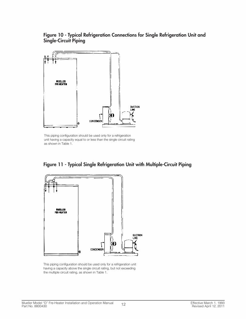
Figure 10 - Typical Refrigeration Connections for Single Refrigeration Unit and Single-Circuit Piping
Figure 11 - Typical Single Refrigeration Unit with Multiple-Circuit Piping
This piping configuration should be used only for a refrigerationunit having a capacity equal to or less than the single circuit ratingas shown in Table 1.
This piping configuration should be used only for a refrigeration unithaving a capacity above the single circuit rating, but not exceedingthe multiple circuit rating, as shown in Table 1.

Mueller Model “D” Fre-Heater Installation and Operation Manual Effective March 1, 1993Part No. 8800430 Revised April 12, 2011
Figure 12 - Typical Dual Refrigeration Unit Piping
Figure 13 - Fre-Heater Location with Hot Gas Defrost Valve, Oil Separator, and/or Discharge Muffler in System
13
This piping configuration should be used for refrigeration unitswithin the range of the per circuit ratings as shown in Table 1.

Mueller Model “D” Fre-Heater Installation and Operation Manual Effective March 1, 1993Part No. 8800430 Revised April 12, 2011
Figure 14 - Typical Heat Pump Refrigerant Piping Diagram
2.7 Electrical Connections for Model “DE” Fre-Heater
A separate 30A 240V branch circuit must be installed by a qualified electrician for heating elementoperation. In addition, a 24V line from the refrigeration unit circuit must be connected to theregulating/limiting thermostats and solenoid. All wiring must comply with the National Electrical Codeand any local codes.
The electric heating element is prewired to the conduit box in the top of the Fre-Heater. Supply circuitconnections should be made to the red and black wires in this compartment. The supply circuit groundmust be connected to the green grounding lug in the conduit box to protect the user from possibleelectrical shock. Use only copper conductors for these connections. See Figure 15 for wiring diagram.
A separate circuit for regulating the refrigerant heated water temperature must originate from therefrigeration unit power supply circuit. It should be protected with a 5-amp in-line fuse. This circuitconnects the thermostats on the water heater in series with the water dump valve (or the optional HotGas Bypass solenoid). Class I wiring should be used in the circuit. See Figure 15 for connection details.
DANGER: When installing or servicing electrical components on this unit, turn both the heating element andcondensing unit power supplies off to avoid the possibility of electrical shock.
IMPORTANT: The tank must be full of water before the power is turned on. The heating element will bedamaged if it is energized even for a short period of time while the tank is empty.
14
MUELLERFRE-HEATER
SUCTIONLINE
HEAT RECLAIMVALVE
HEAT/COOLVALVE
OUTDOOR COIL
INDOOR COIL
CHECK VALVE
!

Mueller Model “D” Fre-Heater Installation and Operation Manual Effective March 1, 1993Part No. 8800430 Revised April 12, 2011
2.8 Special Model “DE” Operating Instructions
The electrical heating element in Model “DE” Fre-Heaters allows a reserve of hot water to be stored inthe top of the tank when refrigeration unit usage is low or when high water output is desired. Thethermostat for the electric heating element has been set at the factory for 140°F to reduce the risk of ascald injury. Should it be necessary to change this setting, turn off the power to both the water heaterand the refrigeration unit, remove the access plate, and adjust the temperature pointer to the desiredtemperature (shown approximately on the dial) with a screwdriver. Be careful not to disturb the plasticshield covering the electrical connections. The use of higher settings for the thermostat reduces theamount of savings that the refrigerant heat recovery provides.
DANGER: Hydrogen gas can be produced in a hot water system served by this heater that has not been used fora long period or time (generally two weeks or more). Hydrogen gas is extremely flammable. To reduce the risk ofinjury under these conditions, it is recommended that a hot water faucet be opened for several minutes beforeusing any electrical appliance connected to the hot water system. If hydrogen is present, there will probably bean unusual sound such as air escaping through the pipe when the water begins to flow. There should be nosmoking or open flame near the faucet at the time it is open.
The electrical heating element circuit contains controls that disconnect the electrical power to theelement should the tank water temperature rise above 190°F. This is a non-resetting-type control so itwill need to be reset each time the tank temperature reaches 190°F.
2.9 Maintenance
In order to achieve the maximum life from your Model “D” Fre-Heaters the following should be doneannually:
1. Remove and check at least one of the two anode rods. If the anode is 33% or more consumed,both anode rods should be replaced.
2. Drain and backflush the water tank running enough water from the water inlet or drain to removeall loose scale which has collected in the bottom of the water tank.
3. Check the operation of the pressure/temperature relief valve by manually operating it to see that itwill freely flow water should it be required to do so. If there is any doubt that it will not functionproperly, replace it.
4. Check all water fittings, valves, etc. to be sure there are no water leaks. Repair as necessary.
5. Check the operation of all controls such as the hot gas bypass valve aquastat, electric elementcontrols, refrigeration head pressure controls, or any other controls necessary for the properoperation of the Fre-Heater and the refrigeration and/or air conditioning systems it is connected to.
NOTICE: All illustrations and diagrams in these instructions are schematic suggestions only. They DO NOT attempt to
address all of the important design considerations such as pipe sizing and configuration or the selection and placement of
major system components. Every installation must follow known and accepted industry safety practices and various code or
legal requirements.
15

Mueller Model “D” Fre-Heater Installation and Operation Manual Effective March 1, 1993Part No. 8800430 Revised April 12, 2011
Figure 15 - Model “DE” Wiring Diagram
16
CONDENSING UNIT
PILOT DUTYCIRCUITONLY
24 VOLTS10 WATT
HI-LIMITTHERMOSTAT
HEATINGELEMENT4500 W
CUSTOMER SUPPLIEDFUSED DISCONNECT 25 AMP
POWER SUPPLY208-240/50-60/1
NOTES:
1. WIRING SHOWN DOTTED IS FURNISHED BY INSTALLER AND MUST CONFORM TO APPLICABLE ELECTRICAL CODES.
2. IF IINSTALLED IN CANADA, WIRING BETWEEN THE FRE-HEATER AND REMOTE COMPONENTS MUST BE FIELD WIRED TO CONFORM TO REQUIREMENTS OF PART 1 OF THE CANADIAN ELECTRICAL CODE.
3. ALL ENFORCED ELECTRICAL CODES MUST BE FOLLOWED DURING INSTALLATION, SERVICE, AND/OR OPERATION OF THIS EQUIPMENT.

Mueller Model “D” Fre-Heater Installation and Operation Manual Effective March 1, 1993Part No. 8800430 Revised April 12, 2011
SECTION 3.0 - INSTRUCTIONS FOR WATER TEMPERATURE LIMIT AND3-WAY HEAT RECLAIM VALVE (FOR REFRIGERANT), PART NO. 8804796
3.1 Solenoid Valve Installation
Three-way heat reclaim valve (Mueller Part Nos. 8801856, 8801857, 8804340, or 8804341).
• The refrigerant must be recovered before cutting the refrigerant lines for the installation of thethree-way heat reclaim valve.
• Accepted refrigeration practices must be used while installing the valve. These practices are ofcommon knowledge to the experienced refrigeration serviceman, and only an experiencedserviceman should undertake the installation of the solenoid valve.
• The installation location of the valve should be as close as practical to the refrigeration compressor.
• The valve should be installed in a vertical position, coil up, and supported by hangers.
• A check valve must be installed in the refrigerant line between the Fre-Heater and the tee as shownin Figure 17.
• Suggested refrigeration piping of the valve in a typical Model “D” or “DE” Fre-Heater system isillustrated in Figure 17. See Table 4 for check valve sizing.
• Piped in the suggested manner, the valve coil will be energized when water heating is needed.When the hot water demand is satisfied, the valve will be de-energized.
Table 2 - Three-Way Heat Reclaim Valves for Refrigerants 22 and 507
Figure 16 - Three-Way Heat Reclaim Valves
17
Part MOPD Safe Working Standard Coil Ratings ConnectionNo. (psi) Pressure (psi) Volts/Cycles Watts Port Size Size
8804340 300 450 24/50/60 10 5⁄8" 5⁄8" ODF
8801856 300 450 24/50/60 10 3⁄4" 7⁄8" ODF
8801857 300 450 24/50/60 10 11⁄4" 13⁄8" ODF
8804341 300 400 24/50/60 10 2" 21⁄8" ODF

Mueller Model “D” Fre-Heater Installation and Operation Manual Effective March 1, 1993Part No. 8800430 Revised April 12, 2011
Figure 17 - Suggested Refrigeration Piping of Valve for Typical Model “D” or “DE”Fre-Heater System
3.2 Aquastat Installation
• The aquastat bulb well should be installed in a 3/4" circulation connection located on the top headas illustrated in Figure 18.
• The aquastat bulb should be installed in the bulb well and the switch attached to the bulb well. Asmall amount of thermal mastic on the bulb will make the aquastat more sensitive to watertemperature changes and is recommended.
Figure 18 - Suggested Aquastat Piping
18

Mueller Model “D” Fre-Heater Installation and Operation Manual Effective March 1, 1993Part No. 8800430 Revised April 12, 2011
3.3 Electrical Installation
• The Mueller supplied three-way heat reclaim valves are equipped with 24 volt solenoid coils. A 24-volt transformer (Mueller Part No. 8800145) 120-volt/24-volt 40 VA or equal must be used for theirproper operation. Two solenoid valves may be operated from one transformer.
• The aquastat (Mueller Part No. 8800144) is a universal type control and care must be taken to wirethe solenoid valve to the “common” and the “open on rise” terminals. The “close on rise” terminalsare NOT used.
• All electrical wiring must be done in accordance with the national and local electrical code.
• The 120 volt primary circuit of the transformer may be supplied from any convenient constant 120volt power source.
• The electrical components should be wired in accordance with the diagram in Figure 19.
Figure 19 - Wiring of Electrical Components
3.4 Checkout and Test Run
• On completion of the installation, the refrigeration system should be checked for leaks and propercharge. The water system should be checked for leaks and trapped air, and solenoid valve shouldbe checked for proper operation.
• To check the solenoid valve operation, run the system until the hot water demand is satisfied. Thesolenoid valve should de-energize, and the hot refrigerant gas should all be channeled directly tothe condenser. Then draw off enough hot water to allow the solenoid valve to energize. The hotrefrigerant gas should again be channeled through the Fre-Heater for water heating.
• The installation should not be considered complete until the valve operation has been fullychecked out.
19
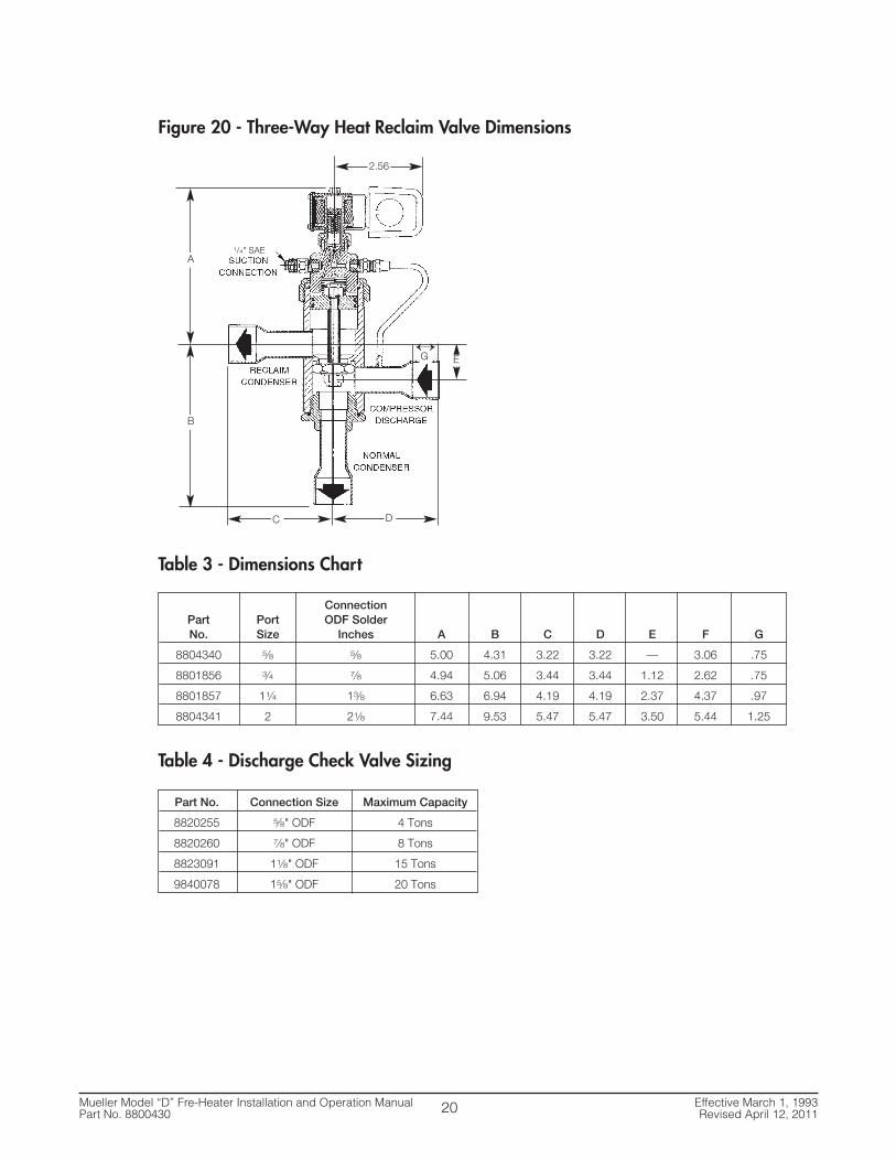
Figure 20 - Three-Way Heat Reclaim Valve Dimensions
Table 3 - Dimensions Chart
Table 4 - Discharge Check Valve Sizing
2.56
G E
C
B
A
D
↕
1/4" SAE
ConnectionPart Port ODF SolderNo. Size Inches A B C D E F G
8804340 5⁄8 5⁄8 5.00 4.31 3.22 3.22 — 3.06 .75
8801856 3⁄4 7⁄8 4.94 5.06 3.44 3.44 1.12 2.62 .75
8801857 11⁄4 13⁄8 6.63 6.94 4.19 4.19 2.37 4.37 .97
8804341 2 21⁄8 7.44 9.53 5.47 5.47 3.50 5.44 1.25
Part No. Connection Size Maximum Capacity
8820255 5⁄8" ODF 4 Tons
8820260 7⁄8" ODF 8 Tons
8823091 11⁄8" ODF 15 Tons
9840078 15⁄8" ODF 20 Tons
Mueller Model “D” Fre-Heater Installation and Operation Manual Effective March 1, 1993Part No. 8800430 Revised April 12, 201120
Mueller Model “D” Fre-Heater Installation and Operation Manual Effective March 1, 1993Part No. 8800430 Revised April 12, 2011
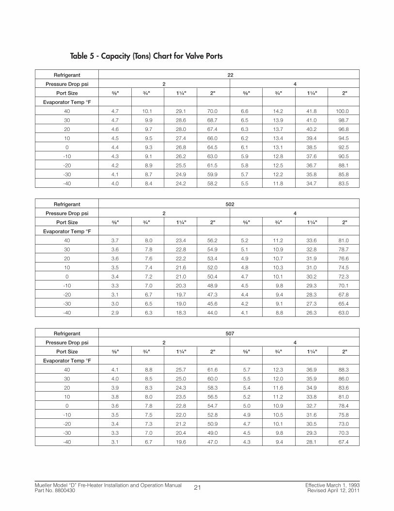
Table 5 - Capacity (Tons) Chart for Valve Ports
21
Refrigerant 22
Pressure Drop psi 2 4
Port Size 5⁄8" 3⁄4" 11⁄4" 2" 5⁄8" 3⁄4" 11⁄4" 2"
Evaporator Temp °F
40 4.7 10.1 29.1 70.0 6.6 14.2 41.8 100.0
30 4.7 9.9 28.6 68.7 6.5 13.9 41.0 98.7
20 4.6 9.7 28.0 67.4 6.3 13.7 40.2 96.8
10 4.5 9.5 27.4 66.0 6.2 13.4 39.4 94.5
0 4.4 9.3 26.8 64.5 6.1 13.1 38.5 92.5
-10 4.3 9.1 26.2 63.0 5.9 12.8 37.6 90.5
-20 4.2 8.9 25.5 61.5 5.8 12.5 36.7 88.1
-30 4.1 8.7 24.9 59.9 5.7 12.2 35.8 85.8
-40 4.0 8.4 24.2 58.2 5.5 11.8 34.7 83.5
Refrigerant 502
Pressure Drop psi 2 4
Port Size 5⁄8" 3⁄4" 11⁄4" 2" 5⁄8" 3⁄4" 11⁄4" 2"
Evaporator Temp °F
40 3.7 8.0 23.4 56.2 5.2 11.2 33.6 81.0
30 3.6 7.8 22.8 54.9 5.1 10.9 32.8 78.7
20 3.6 7.6 22.2 53.4 4.9 10.7 31.9 76.6
10 3.5 7.4 21.6 52.0 4.8 10.3 31.0 74.5
0 3.4 7.2 21.0 50.4 4.7 10.1 30.2 72.3
-10 3.3 7.0 20.3 48.9 4.5 9.8 29.3 70.1
-20 3.1 6.7 19.7 47.3 4.4 9.4 28.3 67.8
-30 3.0 6.5 19.0 45.6 4.2 9.1 27.3 65.4
-40 2.9 6.3 18.3 44.0 4.1 8.8 26.3 63.0
Refrigerant 507
Pressure Drop psi 2 4
Port Size 5⁄8" 3⁄4" 11⁄4" 2" 5⁄8" 3⁄4" 11⁄4" 2"
Evaporator Temp °F
40 4.1 8.8 25.7 61.6 5.7 12.3 36.9 88.3
30 4.0 8.5 25.0 60.0 5.5 12.0 35.9 86.0
20 3.9 8.3 24.3 58.3 5.4 11.6 34.9 83.6
10 3.8 8.0 23.5 56.5 5.2 11.2 33.8 81.0
0 3.6 7.8 22.8 54.7 5.0 10.9 32.7 78.4
-10 3.5 7.5 22.0 52.8 4.9 10.5 31.6 75.8
-20 3.4 7.3 21.2 50.9 4.7 10.1 30.5 73.0
-30 3.3 7.0 20.4 49.0 4.5 9.8 29.3 70.3
-40 3.1 6.7 19.6 47.0 4.3 9.4 28.1 67.4

SECTION 4.0 - BTUH ESTIMATED CAPACITY
4.1 Btuh Estimated Capacity
The estimated Btuh capacity per circuit for Model “D” and “DE” Fre-Heaters is shown in Table 5. Thistable is very useful for estimating heat recovery for Fre-Heaters. However, you should recognize that itis based on averages, and actual heat recovery will vary with the amount of superheat and otherfactors, such as equipment, installation, and operating conditions.
Input water temperature, refrigeration tonnage, refrigeration run time, and water flow rate are four ofthe more important variables which must be considered when estimating heat recovery. As a generalrule, the greatest heat recovery will be obtained at water flows over 1.5 gpm, and maximum watertemperatures of 120°F or less.
It is difficult to accurately predict exact heat recovery because both the refrigeration and water systemsare dynamic systems, and as such very seldom operate under any given set of conditions for aprolonged period of time.
Table 6 - Model “D” Fre-Heater Estimated Per Circuit Btuh Recovery
*Use this table if actual Btuh (tons) of cooling capacity is unknown.
Notes:To use the above tables, all compressor sizes must be converted to tons.
Stay with refrigeration tonnages listed in the Model “D” Technical Specifications Table when planningapplications and estimating heat recovery.
These tables are averages (based on 1 GPM or less flow rate). These averages are based on the averageheat recovery of numerous installations. The actual heat recovery on any given installation may be higheror lower depending on a number of variable factors. Some of these factors are inlet water temperature,water flow rate, type of refrigeration equipment, type of refrigerant, condensing temperature, andrefrigerant superheat. All variable factors must be considered when calculating actual heat recovery.
D-120, D2-120, DH-120, D-50 Per Circuit D2-50 Per Circuit D2-80 Per Circuit & DA-120 Per Circuit
Tons Btuh Tons Btuh Tons Btuh Tons Btuh
.5 4,000 .5 2,700 1.0 4,500 1.0 9,000
1.0 5,400 .75 3,600 1.5 6,000 1.5 13,000
1.5 7,200 1.0 4,200 2.0 8,000 2.0 14,000
2.0 8,400 1.5 5,900 3.0 11,500 3.0 16,000
3.0 11,800 2.0 7,500 4.0 13,000 4.0 19,000
4.0 15,000 2.5 8,400 5.0 14,500 5.0 20,000
3.0 9,500 7.5 and up 22,000
3.5 11,000
4.0 12,000
Average HP/Tons Conversion Chart*
High Temperature Application (Air Conditioning) 1 HP = 1 Ton
Medium Temperature Application (Refrigerators and Ice Makers) 1 HP = .75 Ton
Low Temperature Application (Freezers) 1 HP = .5 Ton
Mueller Model “D” Fre-Heater Installation and Operation Manual Effective March 1, 1993Part No. 8800430 Revised April 12, 201122

Mueller Model “D” Fre-Heater Installation and Operation Manual Effective March 1, 1993Part No. 8800430 Revised April 12, 2011
SECTION 5.0 - FRE-HEATER EQUIPMENT MARKINGS
5.1 Label No. 8805299, Warning Label - R-22
5.2 Label No. 8801149, Warning Label - Disconnecting Power
5.3 Label No. 8802732, Warning Label - Pressure Relief
5.4 Label No. 8800996, Copper Conductor
23
WA R N I N GTHIS EQUIPMENT CONTAINS R-22 HYDROCHLOROFLUOROCARBON (HCFC CLASS II)A SUBSTANCE THAT, IF RELEASED INTO THE ENVIRONMENT, WILL CONTRIBUTE TO A SERIOUS PUBLIC HEALTH AND ENVIRONMENTAL PROBLEM BY DEPLETING THE OZONE LAYER. OZONE LAYER DEPLETION INCREASES THE RISK OF SKIN CANCER AND OTHER DISEASESIN HUMANS AND IS HARMFUL TO PLANT AND ANIMAL LIFE.
THIS EQUIPMENT SHALL BE SERVICED AND DISPOSED OF ONLY IN ACCORDANCE WITH THE OZONE DEPLETING SUBSTANCES REGULATION - CLEAN ENVIRONMENT ACT.
N.B. This regulation is consolidated to September 30, 1992.
LE PRÉSENT ÉQUIPMENT CONTIENT R-22 HYDROCHLOROFLUOROCARBON (HCFC CLASS II)UNE SUBSTANCE QUI, LORSQU’ÉMISE DANS L’ENVIRONNEMENT, CONSTITUE UN SÉRIEUX DANGER A LA SANTÉ PUBLIQUE ET AL’ENVIRONNEMENT EN APPAUVRISSANT LA COUCHE D’OZONE. L’APPAUVRISSEMENT DE LA COUCHE D’OZONE AUGMENTE LES RISQUES DE CANCER DE LA PEAU ET D ’AUTRES MALADIES CHEZ LES HUMAINS ET CONSTITUE UN DANGER A LA VIE VÉGÉTALE ET ANIMALE.
LE PRÉSENT ÉQUIPEMENT EST MIS EN SERVICE ET N’EST ÉLIMINÉ QU’EN CONFORMITÉ DU RÉGLEMENT SUR LES SUBSTANCESAPPAUVRISSANT LA COUCHE D’OZONE - LOI SUR L’ASSAINISSEMENT DE L’ENVIRONNEMENT .
N.B. Le présent réglement est refondu au 30 septembre 1992.
ESTE EQUIPO CONTIENE FLUOROCARBURO HIDROCLORADO R-22 (HCFC CLASS II )(Escriba el nombre de la substancia empobrecedora de la capa de ozono.)
UNA SUBSTANCIA QUE, SI SE SUELTA AL MEDIO AMBIENTE, CONSTITUIRA UN SERIO PELIGRO PARA EL AMBIENTE Y LA SALUD PUBLICAAL EMPOBRECER LA CAPA DE OZONO. EL EMPOBRECIMIENTO DE LA CAPA DE OZONO AUMENTA EL RIESGO DE CANCER A LA PIEL YOTRAS ENFERMEDADES EN LOS SERES HUMANOS Y ES TAMBIEN DAÑINO PARA LA VIDA DE LAS PLANTAS Y LOS ANIMALES.
EL MANTENIMIENTO Y LA ELIMINACION DE ESTE EQUIPO SOLO SE PODRA REALIZAR EN CUMPLIMIENTO CON LAS NORMAS SOBRE LASSUBSTANCIAS EMPOBRECEDORAS DE LA CAPA DE OZONO - LEY PARA LA CONSERVACION DEL AMBIENTE LIMPIO.
N.B. La presente norma se ha consolidado hasta el 30 de septiembre de 1992. 8805299
WARNINGDisconnect both condensingunit and Fre-Heater® from mainpower supply before servicing.
Antes de empezar a dar servicioo reparar la unidad condensado-ra o el Fre-Heater®, es indispens-able desconectarios del sumin-istro de corriente eléctrica.
AVERTISSEMENTSeparez l’unité réfrigérant etFre-Heater® du câble de distribu-tion avant de réparer.
8801149
PELIGRO
WARNING
AVERTISSEMENT
PRESSURE RELIEF VALVE LIMITING THEPRESSURE TO 1000kPA MUST BEINSTALLED!
UNE SOUPAPE DE SÉCURITÉ LIMITANTLA PRESSION A 1000kPA DOIT ETREINSTALLÉE.
8802732
USE COPPER CONDUCTORS ONLY

Mueller Model “D” Fre-Heater Installation and Operation Manual Effective March 1, 1993Part No. 8800430 Revised April 12, 2011
5.5 Label No. 8801888, Warning Label - Hot Water
5.6 Label No. 3791, Hot
5.7 Label No. 3792, Cold
5.8 Label No. 8822705, CSA LR 67608 and USK
5.9 Label No. 8820623, Electrical Warning
5.10 Label No. 8800215, Pressure Relief
24
HOT WATER CAN PRODUCE THIRDDEGREE BURNS IN 6 SECONDS AT60°C (140°F), IN 30 SECONDS AT 54°C(130°F). THERMOSTATS WERE FACTO -RY SET AT 60°C+ (140°F). CONTACTQUALIFIED SERVICE PERSONNEL FORADJUSTMENTS.
EL AGUA CALIENTE PUEDE PRODUCIRQUEMADURAS DE TERCER GRADOS EN6 SEGUNDOS A 60°C (140°F), EN 30SEGUNDOS A 54°C (130°F), LOS TER-MOSTATOS SE AJUSTARON EN LA FAB-RICA A 60°C+ (140°F) COMUNIQUESECON PERSONAL CALIFICADO DE SERVI-CIO PARA ARREGLOS.
MISE EN GARDE, L’EAU CHAUDE PEUTCAUSER DES BRULURES GRAVES EN 6SECONDES, A 60°C (140°F), EN 30 SEC-ONDES A 54°C (130°F), LES THER-MOSTATS DE CE CHAUFFE-EAU ONTETE REGLES A L’AVANCE A 60° C+(140°F). POUR MODIFIER LES POINTSDE CONSIGNE DES THERMOSTATSCONSULTEZ UN SPECIALISTE.
8801888
WARNING
PELIGRO
AVERTISSEMENT
HOT3791
COLD3792
LR67608NPI 8822705
PRESSURE RELIEF
88002157901

Mueller Model “D” Fre-Heater Installation and Operation Manual Effective March 1, 1993Part No. 8800430 Revised April 12, 2011
5.11 Label No. 8801408, Attention
5.12 Label No. 8803611, Fre-Heater Model “DE” Data Plate
5.13 Label No. 31433, Fre-Heater Model “D” Data Plate
5.14 Label No. 31246, Fre-Heater Name Plate
25
ATTENTION!Water ConnectionsDo not apply heat to these fittings when makingsweat connect ions to heater. Sweat tubing toadapter before fitting adapter to heater fittings. It isimperative that no heat be applied to these fittingsas they contain a nonmetallic liner.
Relief ValveRelief valve installation temperature- and pressure-protective equipment is required by local codes, butnot less than a combination temperature- and pres-sure-relief valve device certified as meeting therequirements in the listing requirements for reliefvalves and automatic gas shut-off devices for hotwater supply systems, ANSI Z21.22, by a nationallyrecognized testing laboratory that maintains period-ic inspection of production of listed equipment ormaterials. The valve shall be so oriented or provid-ed with tubing that any discharge can exit onlywithin 6" of or at any distance below the structuralfloor and will not contact any live electrical part.Omission or improper installation of the tempera-ture- and pressure-relief valve voids the manufac-turer’s warranty and liability.
6904 8801408
0502 8803611
MODELNUMBER
PARTNUMBER
REFRIGERANTWORKINGPRESSURE
REFRIGERANTTYPE
PSIG
kPa
TANK WORKING/TEST PRESSURES
TANKCAPACITY
PSIG
kPa
SERIALNUMBER
VOLTAGE
AMPERE
HZ
NUMBER OFCIRCUITS
MAXIMUM FUSE SIZE
WATTSPHASE
TWO WIRES WITH GROUND
MINIMUM CIRCUITAMPACITY
U.S.GALLONS
MODEL “DE” FRE-HEATER®
®
P.O. BOX 828 • SPRINGFIELD, MISSOURI 65801-0828, U.S.A.
0502 31433
MODEL “D” FRE-HEATER®
MODELNUMBER
PARTNUMBER
SERIALNUMBER
REFRIGERANTWORKING PRESSURE
REFRIGERANTTYPE
NUMBER OFCIRCUITS
PSIG
kPa
TANK WORKING / TEST PRESSURE
TANKCAPACITY
PSIG
U.S.GALLONS
kPa
®
P.O. BOX 828 • SPRINGFIELD, MISSOURI 65801-0828, U.S.A.
5911 Fre-Heater®31246
®

Mueller Model “D” Fre-Heater Installation and Operation Manual Effective March 1, 1993Part No. 8800430 Revised April 12, 2011
5.15 Label No. 8820454, Important! Dry Nitrogen Gas
5.16 Label No. 8823999, Attention
5.17 Label No. 9901403, In
5.18 Label No. 9901404, Out
5.19 Label No. 30397, Stainless Steel
5.20 Label No. 8824816, CRN
26
IMPORTANTTHIS EQUIPMENT CONTAINS A HOLDING CHARGE OF DRYNITROGEN GAS. SLOWLY RELEASE PRESSURE THROUGH SERVICEPORTS OR SCHRADER VALVES BEFORE REMOVING FITTINGS.
EVACUATE THE SYSTEM TO 500 MICRONS BEFORE CHARGINGWITH REFRIGERANT. DISCARD THIS TAG UPON CHARGING SYSTEMWITH REFRIGERANT AND APPLY A SYSTEM REFRIGERANTSPECIFICATION DECAL.
NOTE: IT IS THE TECHNICIAN’S RESPONSIBILITY TO COMPLY WITHALL CURRENT REFRIGERANT USAGE REGULATIONS.
(11/94) 8820454
ATTENTIONPLEASE REFER TO THE WIRINGDIAGRAM FOR CONTROL CIRCUITWIRING SPECIFICATIONS.0010 8823999
IN 9901403
OUT9901404
®
StainlessSteel
CRN NUMBER FOR BRITISH COLUMBIA: OH4249.1CRN NUMBER FOR ALL OTHER PROVIDENCES: OH8902.50309 8824816

SECTION 6.0 - APPENDIX A
6.1 Model “D” Fre-Heater Thermal Expansion Tank Installation for Dairy Farm Applications
Mueller is now requiring that a thermal expansion tank be installed on all Model “D” Fre-Heaters usedon dairy farm applications. Without the installation of the thermal expansion tank, the Fre-Heater warrantymay be void at the discretion of the Mueller Dairy Farm Equipment Service Department.
Thermal expansion will occur in all closed tank water heating applications. For example, a closed tankwith an initial pressure of 50 psig will reach a pressure of 250 psig with a temperature rise of just 10°F,or 40 gallons of water at 40°F will expand to 41 gallons at 160°F.
The use of a thermal expansion tank will absorb these pressures and help eliminate premature Fre-Heater failure. The temperature-pressure relief valve is intended as a safety device and should not berelied upon to perform this function.
The following diagram shows the proper installation method for a thermal expansion tank. Mueller PartNo. 8805175 is available and will work well for this application.
PLEASE NOTE:One thermal expansion tank, Part No. 8805175, is required for every 120-gallon Fre-Heater and/orwater heater storage capacity. For example, a Model “D-120” Fre-Heater installed in series with a 120-gallon water heater would require two expansion tanks installed on the cold water supply line of theModel “D.”
The thermal expansion tank is shipped with 40 pounds of pressure on the diaphragm and must bepressurized to the cut-out pressure of the well pump before it is installed. For example, if the watersupply is a 30 psig cut-in and 50 psig cut-out, then the proper pressure in the thermal expansion tankwould be 50 psig.
If you have any questions or comments, please contact the Dairy Farm Equipment Service Departmentat 1-800-MUELLER (683-5537).
Figure 21 - Thermal Expansion Tank Diagram
COLDWATERSUPPLY
BFP CHECK (OR) PRV VALVE
THERMALEXPANSIONTANK
HOT WATER
Mueller Model “D” Fre-Heater Installation and Operation Manual Effective March 1, 1993Part No. 8800430 Revised April 12, 201127

P.O. Box 828 • Springfield, Missouri 65801-0828, U.S.A.Phone: (417) 575-9000 • 1-800-756-5991 • Fax: 1-800-436-2466www.muel.com • E-mail: [email protected]
©1993-2011 Paul Mueller Company (4/11) 8800430
®


