COPYRIGHT 2002 MIDIAN ELECTRONICS INC. ALL RIGHTS RESERVED. DDU-400 MIDIAN ELECTRONICS, INC. 2302 East 22nd Street Tucson, Arizona 85713 To Order: 1-800-MIDIANS Telephone: (520) 884-7981 Fax: (520) 884-0422 Model DDU-400 DISPATCH DISPLAY UNIT INSTRUCTION MANUAL Model Features • 10 entry ANI recall memory • 137 entry alias database • Auto-mute leading ANI • Alternate function as a repeater access controller • Decodes extended ANI’s through 9999 • 8 message indications including emergency • Easy to read backlit LCD display • Serial printer logging (w/optional cable) MANUAL REVISION: 2006.02.22 COVERS PRODUCT SOFTWARE VERSION(S): 1.1 _____ _____ _____ _____ WITH DECODER VERSION(S): 1.1 _____ _____ _____ _____
Transcript
COPYRIGHT 2002 MIDIAN ELECTRONICS INC. ALL RIGHTS RESERVED. DDU-400
MIDIAN ELECTRONICS, INC. 2302 East 22nd Street Tucson, Arizona 85713 To Order: 1-800-MIDIANS Telephone: (520) 884-7981 Fax: (520) 884-0422
Model DDU-400
DISPATCH DISPLAY UNIT
INSTRUCTION MANUAL
Model Features • 10 entry ANI recall memory • 137 entry alias database • Auto-mute leading ANI • Alternate function as a repeater access controller
• Decodes extended ANI’s through 9999 • 8 message indications including emergency • Easy to read backlit LCD display • Serial printer logging (w/optional cable)
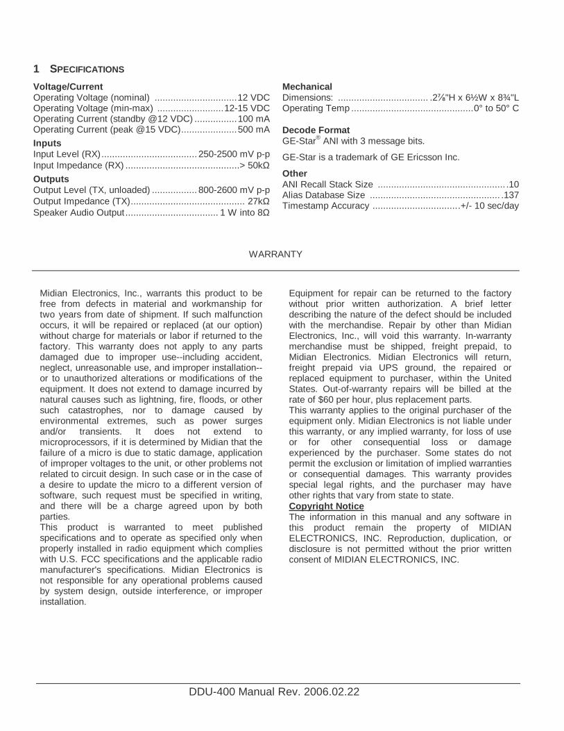
Voltage/Current Operating Voltage (nominal) ...............................12 VDC Operating Voltage (min-max) .........................12-15 VDC Operating Current (standby @12 VDC) ................100 mA Operating Current (peak @15 VDC).....................500 mA
Mechanical Dimensions: .................................. .2⅞"H x 6½W x 8¾"L Operating Temp ..............................................0° to 50° C Decode Format GE-Star® ANI with 3 message bits.
GE-Star is a trademark of GE Ericsson Inc.
Other ANI Recall Stack Size ................................................ .10 Alias Database Size ................................................. .137 Timestamp Accuracy .................................+/- 10 sec/day
WARRANTY
Midian Electronics, Inc., warrants this product to be free from defects in material and workmanship for two years from date of shipment. If such malfunction occurs, it will be repaired or replaced (at our option) without charge for materials or labor if returned to the factory. This warranty does not apply to any parts damaged due to improper use--including accident, neglect, unreasonable use, and improper installation--or to unauthorized alterations or modifications of the equipment. It does not extend to damage incurred by natural causes such as lightning, fire, floods, or other such catastrophes, nor to damage caused by environmental extremes, such as power surges and/or transients. It does not extend to microprocessors, if it is determined by Midian that the failure of a micro is due to static damage, application of improper voltages to the unit, or other problems not related to circuit design. In such case or in the case of a desire to update the micro to a different version of software, such request must be specified in writing, and there will be a charge agreed upon by both parties. This product is warranted to meet published specifications and to operate as specified only when properly installed in radio equipment which complies with U.S. FCC specifications and the applicable radio manufacturer's specifications. Midian Electronics is not responsible for any operational problems caused by system design, outside interference, or improper installation.
Equipment for repair can be returned to the factory without prior written authorization. A brief letter describing the nature of the defect should be included with the merchandise. Repair by other than Midian Electronics, Inc., will void this warranty. In-warranty merchandise must be shipped, freight prepaid, to Midian Electronics. Midian Electronics will return, freight prepaid via UPS ground, the repaired or replaced equipment to purchaser, within the United States. Out-of-warranty repairs will be billed at the rate of $60 per hour, plus replacement parts. This warranty applies to the original purchaser of the equipment only. Midian Electronics is not liable under this warranty, or any implied warranty, for loss of use or for other consequential loss or damage experienced by the purchaser. Some states do not permit the exclusion or limitation of implied warranties or consequential damages. This warranty provides special legal rights, and the purchaser may have other rights that vary from state to state. Copyright Notice The information in this manual and any software in this product remain the property of MIDIAN ELECTRONICS, INC. Reproduction, duplication, or disclosure is not permitted without the prior written consent of MIDIAN ELECTRONICS, INC.
MIDIAN ELECTRONICS INCORPORATED PAGE 3
DDU-400 Manual Rev. 2006.02.22
TABLE OF CONTENTS 1 SPECIFICATIONS ........................................................................................................................... 2
5.4 SETUP MENU ................................................................................................................................... 8
6 SYSTEM ERROR MESSAGES................................................................................................ 12
7 MENU SYSTEM MAP .............................................................................................................. 13
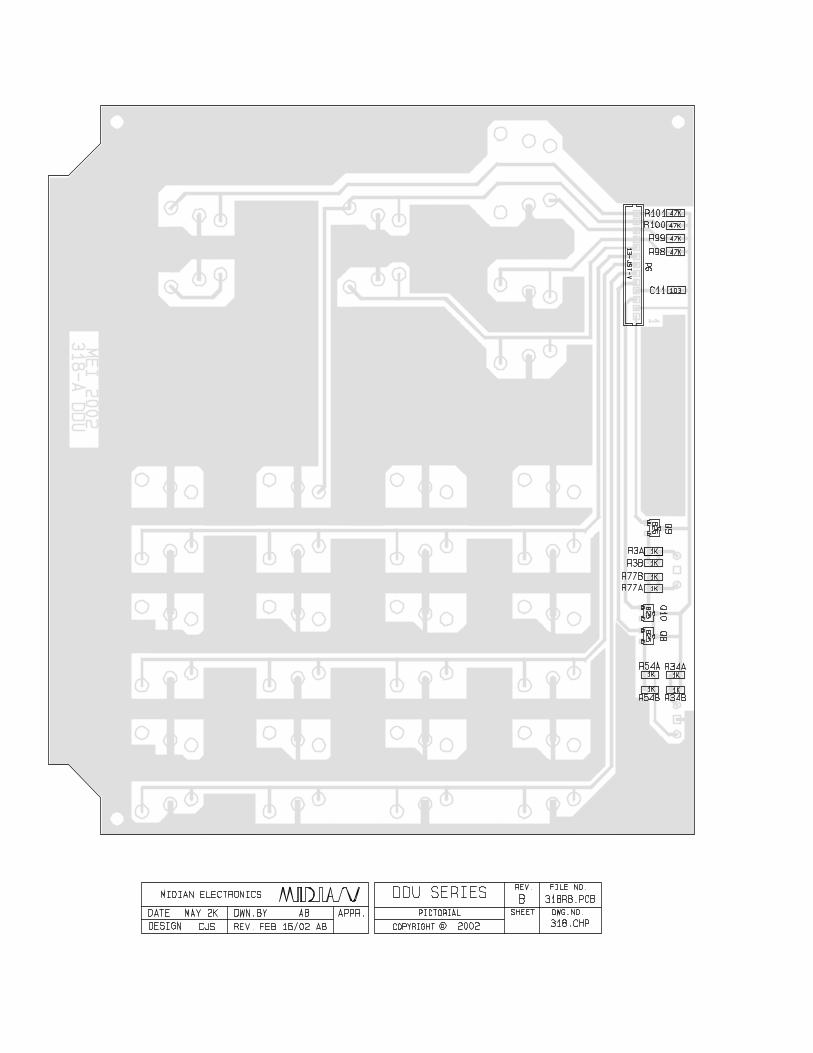
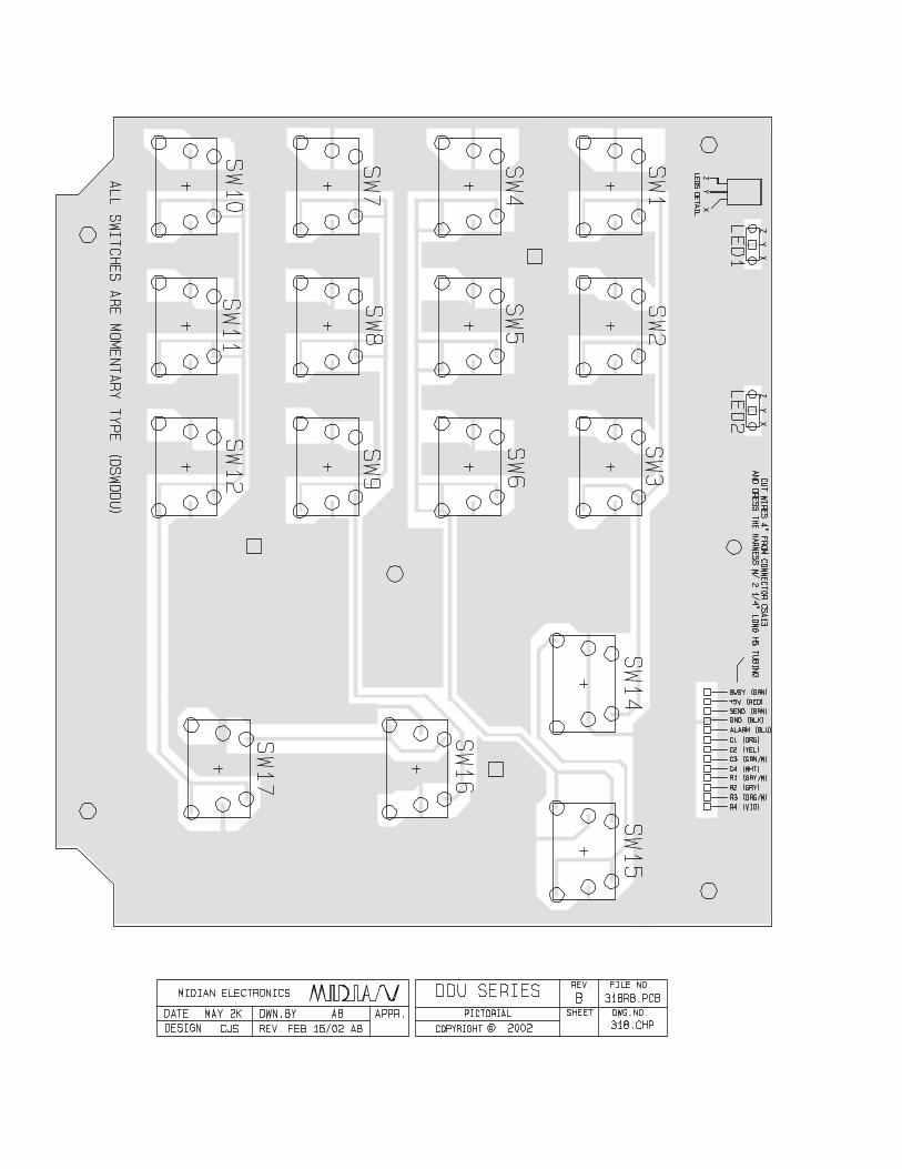
SCHEMATIC PICTORIAL
PAGE 4 MIDIAN ELECTRONICS INCORPORATED
DDU-400 Manual Rev. 2006.02.22
2 OVERVIEW The DDU provides the optimal ANI display decoder solution for small and medium sized radio systems such as those used by taxi fleets, police departments, construction crews, etc.
The last 10 ANI's received can be reviewed at any time. It can store up to 137 aliases in its user database. The user friendly menu system makes it as easy to use as a cell phone. Additional features include emergency status display and the ability to automatically mute incoming leading ANI's
3 INSTALLATION INSTRUCTIONS Installation Note: Midian products utilize CMOS integrated circuits, which are susceptible to damage from high static charges. Be sure to follow standard antistatic procedures when handling, including using grounded workstations and soldering irons and wearing grounding bracelets.
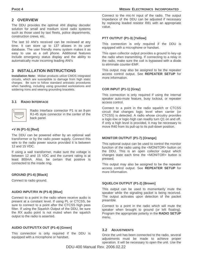
3.1 RADIO INTERFACE
Radio Interface connector P1 is an 8-pin RJ-45 style connector in the center of the back panel.
+V IN (P1-5) [Red]
The DDU can be powered either by an optional wall transformer or by the radio power supply. Connect this wire to the radio power source provided it is between 12 and 15 VDC.
If using a wall transformer, make sure the voltage is between 12 and 15 VDC and the current rating is at least 800mA. Also, be certain that positive is connected to the inside ring.
GROUND (P1-6) [Black]
Connect to radio ground.
AUDIO INPUT/RX IN (P1-8) [Blue]
Connect to a point in the radio where receive audio is present at a constant level. If using PL or CTCSS, be sure to connect to a point after the CTCSS high pass filter. If using the Squelch Output of the DDU, be sure the RX audio point is not muted when the squelch output to the radio is asserted.
AUDIO OUTPUT/TX OUT (P1-4) [Green]
This connection is only required if the DDU is equipped with a microphone or handset.
Connect to the mic-hi input of the radio. The output impedance of the DDU can be adjusted if necessary by replacing leaded resistor R81 with an appropriate value.
PTT OUTPUT (P1-3) [Yellow]
This connection is only required if the DDU is equipped with a microphone or handset.
This open collector output provides a ground to key-up the radio when transmitting. If connecting to a relay in the radio, make sure the coil is bypassed with a diode to eliminate counter-EMF.
This output may also be assigned to be the repeater access control output. See REPEATER SETUP for more information.
COR INPUT (P1-1) [Gray]
This connection is only required if using the internal speaker auto-mute feature, busy lockout, or repeater access control.
Connect to a point in the radio squelch or CTCSS circuit that changes logic level when carrier (or CTCSS) is detected. A radio whose circuitry provides a logic-low or logic-high can readily turn Q1 on and off. If only a high level is provided, it may be necessary to move R40 from its pull-up to its pull-down position.
MONITOR OUTPUT (P1-7) [Orange]
This optional output can be used to control the monitor function of the radio using the <MONITOR> button on the DDU. This is an open collector output which changes state each time the <MONITOR> button is pressed.
This output may also be assigned to be the repeater access control output. See REPEATER SETUP for more information.
SQUELCH OUTPUT (P1-2) [Brown]
This output can be used to momentarily mute the speaker while the signaling packet is being received. The output activates upon detection of the packet preamble.
Connect to a point in the radio which will mute the speaker when brought to ground (or left floating). Program the appropriate polarity in the RADIO SETUP menu.
3.2 ADJUSTMENTS Once the unit has been connected to the radio, several adjustments must be made to achieve proper operation. It will be necessary to open the unit. Use the
MIDIAN ELECTRONICS INCORPORATED PAGE 5
DDU-400 Manual Rev. 2006.02.22
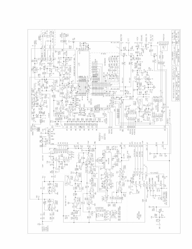
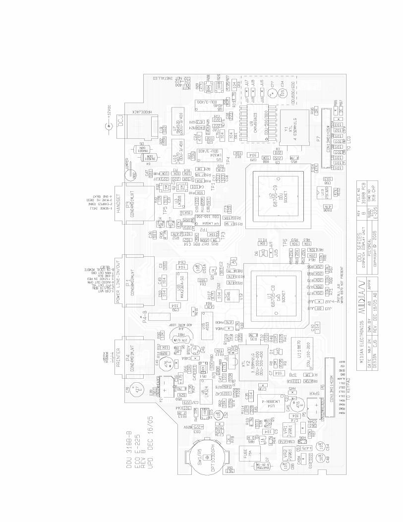
pictorial to identify the location of the following trim pots: R2, R32 near connector P3 and R51 near IC U6.
INPUT LEVEL
Use a service monitor to generate a 1000 Hz test tone at 2/3 of maximum system modulation (typically 3.3 kHz). Measure the voltage appearing at TP1 and adjust R2 such that TP1 is at 230mV RMS.
OUTPUT LEVEL (if using with mic)
Use a service monitor to measure the modulation level generated by the DDU microphone. Speaking loudly should result in full modulation. Adjust R51 accordingly. If necessary, the mic gain can be adjusted using R105.
SPEAKER PRE-AMP
Though the DDU has a volume control knob, it also has an input audio pre-amplifier. While listening to audio on the channel, adjust R32 so that the minimum and maximum volume control settings are at desired levels.
PLL ALIGNMENT
PLL alignment is performed at the factory and normally does not require any adjustment. In the unlikely event PLL alignment is required, the procedure is as follows:
1) Ground Pin 9 of U8.
2) Observe Pin 4 of U8 with a frequency counter or an oscilloscope.
3) Adjust R28 until Pin 4 is at 18 kHz.
4) Remove ground from Pin 9 of U8.
5) Adjust R26 until Pin 4 is at 25.6 kHz.
3.3 CONFIGURATION SETTINGS Once adjustments have been made, it will be necessary to configure the DDU to meet the system requirements. This is done via Menu Mode.
Be sure to set the time of day via TIME SETUP once the DDU is operating as desired. Once the time is set, be sure to leave the unit on at all times or else the time will have to be reset. The time can only be set to the nearest minute. Seconds are kept track of internally and start running the instant the unit is turned-on. It is a good idea to check the time clock monthly as crystal and temperature variances affect the accuracy.
4 BASIC OPERATION
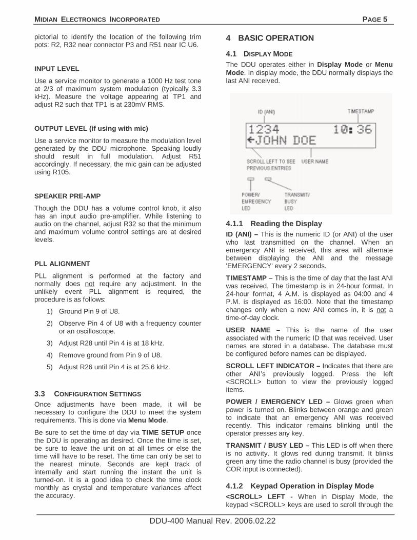
4.1 DISPLAY MODE The DDU operates either in Display Mode or Menu Mode. In display mode, the DDU normally displays the last ANI received.
4.1.1 Reading the Display ID (ANI) – This is the numeric ID (or ANI) of the user who last transmitted on the channel. When an emergency ANI is received, this area will alternate between displaying the ANI and the message 'EMERGENCY' every 2 seconds.
TIMESTAMP – This is the time of day that the last ANI was received. The timestamp is in 24-hour format. In 24-hour format, 4 A.M. is displayed as 04:00 and 4 P.M. is displayed as 16:00. Note that the timestamp changes only when a new ANI comes in, it is not a time-of-day clock.
USER NAME – This is the name of the user associated with the numeric ID that was received. User names are stored in a database. The database must be configured before names can be displayed.
SCROLL LEFT INDICATOR – Indicates that there are other ANI’s previously logged. Press the left <SCROLL> button to view the previously logged items.
POWER / EMERGENCY LED – Glows green when power is turned on. Blinks between orange and green to indicate that an emergency ANI was received recently. This indicator remains blinking until the operator presses any key.
TRANSMIT / BUSY LED – This LED is off when there is no activity. It glows red during transmit. It blinks green any time the radio channel is busy (provided the COR input is connected).
4.1.2 Keypad Operation in Display Mode <SCROLL> LEFT - When in Display Mode, the keypad <SCROLL> keys are used to scroll through the
PAGE 6 MIDIAN ELECTRONICS INCORPORATED
DDU-400 Manual Rev. 2006.02.22
previously logged ANI’s. The scroll left indicator remains present on the screen so long as there are more previous entries to be viewed. The scroll left indicator disappears when the oldest entry is reached.
<SCROLL> RIGHT - A scroll right indicator will appear on the right side of the screen when there are newer entries available for viewing. Press the right <SCROLL> button to view the newer entries. When the last entry is reached, the right scroll indicator disappears.
<#> POUND KEY – Repeatedly pressing the <#> key will always return the DDU to display mode with the last ANI received being shown.
<MONITOR> - This button always controls the monitor function of the radio. Press <MONITOR> to toggle the state of the monitor output to the radio.
<SEND> - Activates the radio PTT switch, placing the radio in transmit mode. This function applies only to units equipped with a microphone.
NUMBER KEYS – The number keys perform no function in display mode. They are used in menu mode for data entry.
<*> STAR KEY – Pressing the <*> will place the DDU in Menu Mode at the main menu.
4.2 MENU MODE The Menu Mode provides the method for configuring the DDU.
4.2.1 Navigating the Menus Press the star key <*> while in Display Mode to place the unit into Menu Mode. Upon entry to Menu Mode, you will be in the Main Menu. The top line of the display indicates this. The bottom line displays an item available for selection, in this case the CLEAR ANI LOG command.
The scroll right symbol on the right side of the display indicates that additional items are available. Press the
right <SCROLL> button to view the next available item. The scroll left symbol will then appear, indicating that the left <SCROLL> button may be used to go back to the previous item.
To select the displayed item, press the <SEND> button (the <SEND> button acts like an ENTER key
when in menu mode). Upon selection, the name of the item will appear on the top line of the display. The bottom line will present additional items for selection. Press the <#> key to return to the previous selection.
4.3 USER DATABASE The user database makes day-to-day operation of the DDU much easier. You can use easy-to-remember names instead of just numbers.
4.3.1 User Database Features The primary purpose of the user database is to associate names with numbers. This way, when an ANI comes in, the name of the person can be displayed along with the ANI.
The DDU can store up to 137 names and ID numbers in its database. The DDU retains the database memory even when switched off.
4.3.2 Setting Up the User Database Begin by compiling a list of names and ID numbers. Give some thought on how you are going to abbreviate the names since only 14 characters per name are available. To begin entering data, select Add User from the USERS menu.
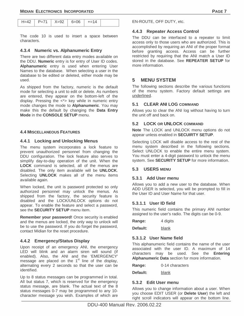
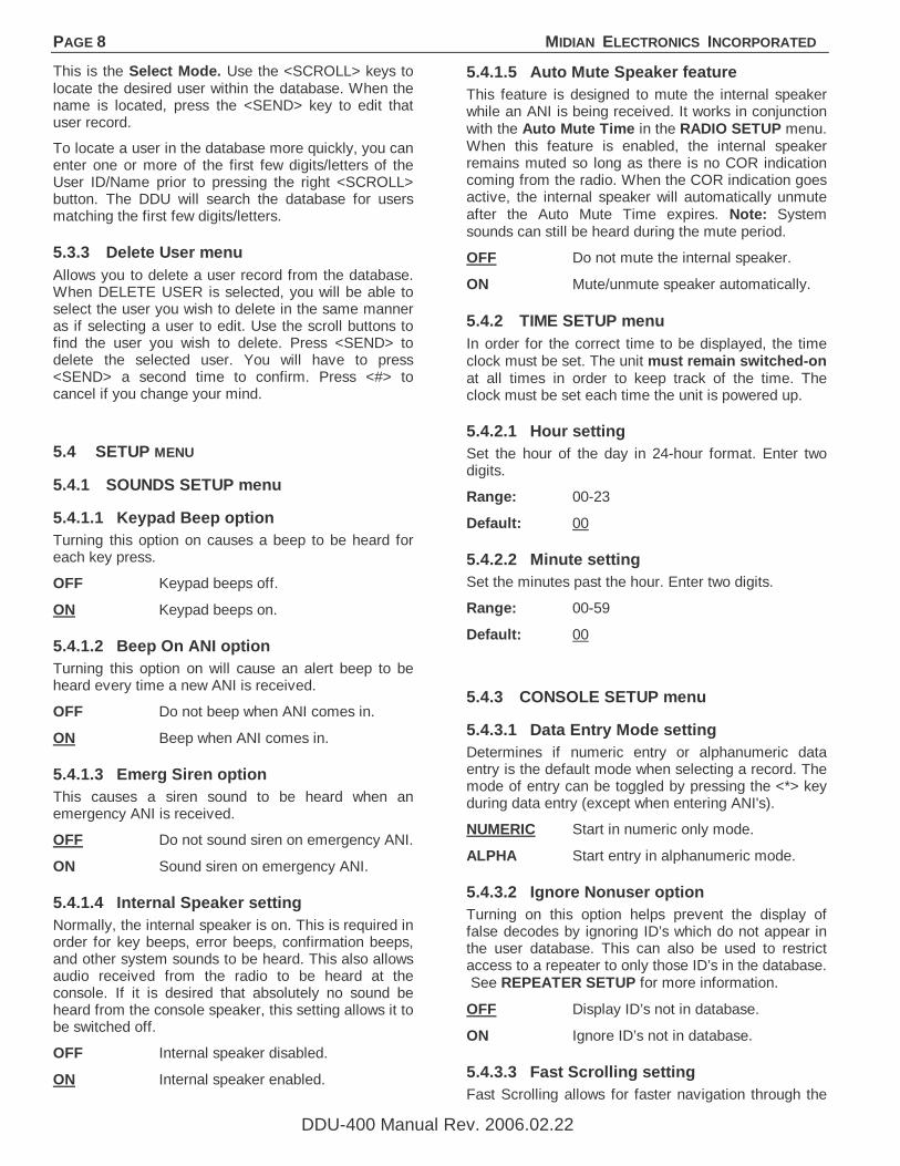
4.3.3 Entering Alphanumeric Data Entering alphabetic characters into the user database using the numeric keypad is easy. All of the letters of the alphabet appear above the numbers on the keypad. For example, the letters ‘A’ ‘B’ and ‘C’ appear on the <2> key.
Alphabetic characters are entered by pressing 2 digits. The first digit is the key with the desired letter appearing on it. The 2nd digit is the position of the letter on that key. For example, the code for the letter ‘C’ is 23 since it is the 3rd letter on the <2> key. The letter ‘T’ is the 1st letter on the <8> key, so its code is 81.
To enter numeric characters in an alphanumeric field, press the <0> key followed by the desired digit. Punctuation characters such as comma <,> and <-> do not appear on the keypad. Special codes have been assigned to allow entry of those characters. Please refer to the following chart
A=21 I=43 Q=72 Y=93 7=07 - =15
B=22 J=51 R=73 Z=94 8=08 = =16
C=23 K=52 S=74 1=01 9=09 * =17
D=31 L=53 T=81 2=02 0=00 / =18
E=32 M=61 U=82 3=03 , =11 # =19
F=33 N=62 V=83 4=04 . =12 Spc=10
G=41 O=63 W=91 5=05 _=13
MIDIAN ELECTRONICS INCORPORATED PAGE 7
DDU-400 Manual Rev. 2006.02.22
H=42 P=71 X=92 6=06 +=14
The code 10 is used to insert a space between characters.
4.3.4 Numeric vs. Alphanumeric Entry There are two different data entry modes available on the DDU. Numeric entry is for entry of User ID codes. Alphanumeric entry is used when entering User Names to the database. When selecting a user in the database to be edited or deleted, either mode may be used.
As shipped from the factory, numeric is the default mode for selecting a unit to edit or delete. As numbers are entered, they appear on the bottom-left of the display. Pressing the <*> key while in numeric entry mode changes the mode to Alphanumeric. You may make this the default by changing the Data Entry Mode in the CONSOLE SETUP menu.
4.4 MISCELLANEOUS FEATURES
4.4.1 Locking and Unlocking Menus The menu system incorporates a lock feature to prevent unauthorized personnel from changing the DDU configuration. The lock feature also serves to simplify day-to-day operation of the unit. When the LOCK command is selected, all of the menus are disabled. The only item available will be UNLOCK. Selecting UNLOCK makes all of the menu items available again.
When locked, the unit is password protected so only authorized personnel may unlock the menus. As shipped from the factory, the security feature is disabled and the LOCK/UNLOCK options do not appear. To enable the feature and select a password, see the SECURITY SETUP menu item.
Remember your password! Once security is enabled and the menus are locked, the only way to unlock will be to use the password. If you do forget the password, contact Midian for the reset procedure.
4.4.2 Emergency/Status Display Upon receipt of an emergency ANI, the emergency LED will blink and an alarm siren will sound (if enabled). Also, the ANI and the 'EMERGENCY' message are placed on the 1st line of the display, alternating every 2 seconds so that the user can be identified.
Up to 8 status messages can be programmed in total. All but status 7, which is reserved for the emergency status message, are blank. The actual text of the 8 status messages 0-7 may be programmed to any 10- character message you wish. Examples of which are
EN-ROUTE, OFF DUTY, etc.
4.4.3 Repeater Access Control The DDU can be interfaced to a repeater to limit access only to those users who are authorized. This is accomplished by requiring an ANI of the proper format before granting access. Access can be further restricted by requiring that the ANI match a User ID stored in the database. See REPEATER SETUP for more information.
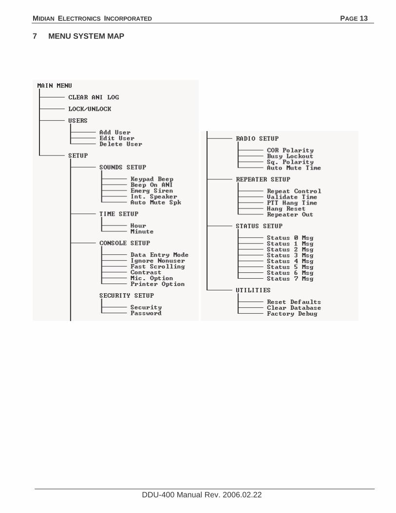
5 MENU SYSTEM The following sections describe the various functions of the menu system. Factory default settings are underlined.
5.1 CLEAR ANI LOG COMMAND Allows you to clear the ANI log without having to turn the unit off and back on.
5.2 LOCK OR UNLOCK COMMAND Note The LOCK and UNLOCK menu options do not appear unless enabled in SECUIRTY SETUP.
Selecting LOCK will disable access to the rest of the menu system described in the following sections. Select UNLOCK to enable the entire menu system. You must enter a 4-digit password to unlock the menu system. See SECURITY SETUP for more information.
5.3 USERS MENU
5.3.1 Add User menu Allows you to add a new user to the database. When ADD USER is selected, you will be prompted to fill in the User ID and User Name for that user.
5.3.1.1 User ID field This numeric field contains the primary ANI number assigned to the user’s radio. The digits can be 0-9.
Range: 4 digits
Default: blank
5.3.1.2 User Name field This alphanumeric field contains the name of the user associated with the user ID. A maximum of 14 characters may be used. See the Entering Alphanumeric Data section for more information.
Range: 0-14 characters
Default: blank
5.3.2 Edit User menu Allows you to change information about a user. When you choose EDIT USER (or Delete User) the left and right scroll indicators will appear on the bottom line.
PAGE 8 MIDIAN ELECTRONICS INCORPORATED
DDU-400 Manual Rev. 2006.02.22
This is the Select Mode. Use the <SCROLL> keys to locate the desired user within the database. When the name is located, press the <SEND> key to edit that user record.
To locate a user in the database more quickly, you can enter one or more of the first few digits/letters of the User ID/Name prior to pressing the right <SCROLL> button. The DDU will search the database for users matching the first few digits/letters.
5.3.3 Delete User menu Allows you to delete a user record from the database. When DELETE USER is selected, you will be able to select the user you wish to delete in the same manner as if selecting a user to edit. Use the scroll buttons to find the user you wish to delete. Press <SEND> to delete the selected user. You will have to press <SEND> a second time to confirm. Press <#> to cancel if you change your mind.
5.4 SETUP MENU
5.4.1 SOUNDS SETUP menu
5.4.1.1 Keypad Beep option Turning this option on causes a beep to be heard for each key press.
OFF Keypad beeps off.
ON Keypad beeps on.
5.4.1.2 Beep On ANI option Turning this option on will cause an alert beep to be heard every time a new ANI is received.
OFF Do not beep when ANI comes in.
ON Beep when ANI comes in.
5.4.1.3 Emerg Siren option This causes a siren sound to be heard when an emergency ANI is received.
OFF Do not sound siren on emergency ANI.
ON Sound siren on emergency ANI.
5.4.1.4 Internal Speaker setting Normally, the internal speaker is on. This is required in order for key beeps, error beeps, confirmation beeps, and other system sounds to be heard. This also allows audio received from the radio to be heard at the console. If it is desired that absolutely no sound be heard from the console speaker, this setting allows it to be switched off.
OFF Internal speaker disabled.
ON Internal speaker enabled.
5.4.1.5 Auto Mute Speaker feature This feature is designed to mute the internal speaker while an ANI is being received. It works in conjunction with the Auto Mute Time in the RADIO SETUP menu. When this feature is enabled, the internal speaker remains muted so long as there is no COR indication coming from the radio. When the COR indication goes active, the internal speaker will automatically unmute after the Auto Mute Time expires. Note: System sounds can still be heard during the mute period.
OFF Do not mute the internal speaker.
ON Mute/unmute speaker automatically.
5.4.2 TIME SETUP menu In order for the correct time to be displayed, the time clock must be set. The unit must remain switched-on at all times in order to keep track of the time. The clock must be set each time the unit is powered up.
5.4.2.1 Hour setting Set the hour of the day in 24-hour format. Enter two digits.
Range: 00-23
Default: 00
5.4.2.2 Minute setting Set the minutes past the hour. Enter two digits.
Range: 00-59
Default: 00
5.4.3 CONSOLE SETUP menu
5.4.3.1 Data Entry Mode setting Determines if numeric entry or alphanumeric data entry is the default mode when selecting a record. The mode of entry can be toggled by pressing the <*> key during data entry (except when entering ANI's).
NUMERIC Start in numeric only mode.
ALPHA Start entry in alphanumeric mode.
5.4.3.2 Ignore Nonuser option Turning on this option helps prevent the display of false decodes by ignoring ID’s which do not appear in the user database. This can also be used to restrict access to a repeater to only those ID’s in the database. See REPEATER SETUP for more information.
OFF Display ID’s not in database.
ON Ignore ID’s not in database.
5.4.3.3 Fast Scrolling setting Fast Scrolling allows for faster navigation through the
MIDIAN ELECTRONICS INCORPORATED PAGE 9
DDU-400 Manual Rev. 2006.02.22
menu system. The DDU can also animate the scrolling of the screen from side-to-side. This provides positive feedback in response to scrolling through menus and the ANI log. If this effect is desired, Fast Scrolling can be disabled.
OFF Animate scrolling from side to side.
ON Scroll at fast speed.
5.4.3.4 Contrast setting Allows the display contrast to be adjusted for best viewing.
LOW Low contrast setting.
HIGH High contrast setting.
5.4.3.5 Mic. Option setting Selects which type of optional microphone accessory is attached to the DDU. This is necessary so that the DDU knows how to treat the external signals.
NONE No microphone.
GOOSENECK Gooseneck style microphone.
PADDLE Paddle style desktop microphone.
HANDSET External handset.
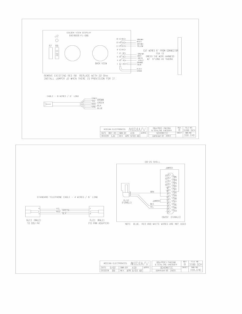
5.4.3.6 Printer Option The DDU, if ordered with the printer cable option, can log the ANI traffic to a serial printer. The printer must have a print buffer and a standard RS-232 port. It must be configured for 9600 baud, 8 data bits, 1 stop bit and no parity. In order to send data to the printer, this option must be on.
OFF Do not send data to printer.
ON Send data to printer.
5.4.4 SECURITY SETUP menu
5.4.4.1 Security setting Allows the security option to be turned on and off. If turned off, the LOCK/UNLOCK menus will not appear.
ON Enable security feature.
OFF Disable security feature.
5.4.4.2 Password setting Sets the password required to UNLOCK the menu system when the Security is turned on. Must be 4 numeric digits.
Range: 4 digits
Default: 0000
5.4.5 RADIO SETUP menu
5.4.5.1 COR Polarity setting Determines which state of the COR (carrier detect) input is considered the active state. When COR is active, the radio channel is busy. If the radio is using PL/CTCSS, it is recommended that the COR Input be connected to a point which goes active when PL is detected.
The COR input is used in conjunction with the Busy Lockout feature. If not connecting the COR input, do not enable Busy Lockout .
LOW Channel is busy when COR is 0V.
HIGH Channel is busy when COR is 5V.
5.4.5.2 Busy Lockout option This option prevents the DDU from transmitting on a busy channel. If this option is ON, the unit will not transmit when the COR input is in the active state. The DDU will wait until the channel is clear and then transmit. When this option is OFF, the unit will transmit regardless of the state of the COR input.
OFF Transmit regardless of COR input.
ON Do not transmit when channel busy.
5.4.5.3 Squelch Polarity setting Determines the active state of the Squelch Output. The Squelch Output can be used to mute incoming ANI packets.
LOW Radio is squelched when the Squelch Output. Is brought to GND.
HIGH Radio is squelched when the Squelch Output is not at GND (floating).
5.4.5.4 Auto Mute Time setting This is used in conjunction with the Auto Mute Speaker feature. This specifies how long the DDU internal speaker will remain muted after the COR input goes active. This value should be set to allow for any key-up delay of the transmitting unit as well as the time it takes for the ANI to complete.
Range: 0000 to 4000 milliseconds
Default: 0300 milliseconds
5.4.6 REPEATER SETUP menu
5.4.6.1 Repeat Control option Allows the DDU to control access to a repeater. Causes the DDU to assert a PTT output to a repeater upon receipt of either: (1) any ANI in the format decoded by the DDU or (2) a valid User ID in the user database. To restrict repeater access to valid User ID’s
PAGE 10 MIDIAN ELECTRONICS INCORPORATED
DDU-400 Manual Rev. 2006.02.22
only, the Ignore Nonuser option in the CONSOLE SETUP must be turned ON. Otherwise, any incoming ANI of the proper format will be considered valid.
Other possible uses of the Repeat Control option include operation of a horn relay or the enabling of a PA speaker. Repeater control output can either be the PTT output, or the MONITOR output (see below).
OFF Repeater control disabled.
ON Repeater control is enabled.
5.4.6.2 Validate Time setting This sets how long after COR becomes active, that the repeater will be keyed prior to receiving a valid decode. This allows time for the incoming ANI to be broadcast by the repeater before it has been validated. If no ANI (or valid User ID) has been decoded during this time, the repeater will be un-keyed. The repeater will remain un-keyed until COR goes inactive.
If set to 0, the repeater will not be keyed until after the ANI (or valid User ID) has been decoded.
Range: 00 to 99 10ths of a second (0.0 - 9.9 s)
Default: 10 10ths of a second (1.0 second)
5.4.6.3 PTT Hang Time setting Once validation has occurred, this sets how long the repeater will remain keyed after COR goes inactive. Once the hang timer expires, a new validation will be required to access the repeater.
Range: 00 to 99 10ths of a second (0.0 - 9.9 s)
Default: 20 10ths of a second (2.0 seconds)
5.4.6.4 Hang Reset setting This setting specifies what is required to reset the PTT hang timer before it expires. This can either be COR or COR+ANI. When set to COR, the hang timer will be reset if COR goes active prior to expiration, allowing the conversation to continue without a new validation. When set to COR+ANI, a new valid ANI will also be required to keep the repeater open.
COR Reset hang timer if COR goes active before the hang time expires.
COR+ANI Require both COR and an ANI (or valid User ID) to reset the hang timer before expiration.
5.4.6.5 Repeater Out setting This setting specifies which output is used to put the repeater into transmit mode when Repeat Control is enabled.
PTT PTT output used to key repeater in Repeat Control mode.
MONITOR MONITOR output used to key repeater in Repeat Control mode.
5.4.7 STATUS SETUP menu
5.4.7.1 Status 0 Msg setting There is a status message for each of the digits 0 through 7. These correspond to message numbers 0-7 supported by many ANI encoder boards including Midian’s ANI-MG. Each status message may be up to 10 alphanumeric characters. If not using status messages, or if certain digits are not used, simply leave those blank. Message 7 is reserved for EMERGENCY, but the text may be changed.
Range: 0-10 characters
Default: blank
5.4.7.2 Status 1 Msg setting See Status 0 Msg setting above.
Range: 0-10 characters
Default: blank
5.4.7.3 Status 2 Msg setting See Status 0 Msg setting above.
Range: 0-10 characters
Default: blank
5.4.7.4 Status 3 Msg setting See Status 0 Msg setting above.
Range: 0-10 characters
Default: blank
5.4.7.5 Status 4 Msg setting See Status 0 Msg setting above.
Range: 0-10 characters
Default: blank
5.4.7.6 Status 5 Msg setting See Status 0 Msg setting above.
Range: 0-10 characters
Default: blank
5.4.7.7 Status 6 Msg setting See Status 0 Msg setting above.
Range: 0-10 characters
Default: blank
5.4.7.8 Status 7 Msg setting See Status 0 Msg setting above.
Range: 0-10 characters
MIDIAN ELECTRONICS INCORPORATED PAGE 11
DDU-400 Manual Rev. 2006.02.22
Default: EMERGENCY
5.4.8 UTILITIES menu
5.4.8.1 Reset Defaults This will reset all the parameters listed above to the factory default settings. The contents of the user database will not be affected.
5.4.8.2 Clear Database This will clear the user database of all ID's and User Names. The contents of the other parameters listed above will not be affected.
5.4.8.3 Factory Debug This is used by the factory for product testing. Do not select this function unless directed to do so by Midian Technical Support. Damage to the unit may result.
PAGE 12 MIDIAN ELECTRONICS INCORPORATED
DDU-400 Manual Rev. 2006.02.22
6 SYSTEM ERROR MESSAGES
CHANNEL BUSY
Reason: An attempt was made to transmit on a busy channel with busy lockout enabled.
Solution: Wait until the channel is clear before transmitting.
DATABASE EMPTY
Reason: An attempt was made to edit or delete a user when the database was empty.
Solution: These functions do not apply when the database is empty.
DATABASE FULL
Reason: An attempt was made to add a user to the database and there is no more room. The maximum number of user aliases of 137 cannot be exceeded.
Solution: Remove any old user names that are no longer in service. If this is not possible, contact Midian to learn about our Computer Aided Dispatch (CAD) fleet management systems which can handle many more users.
DATABASE ERROR
Reason: One or more entries in the user database has been corrupted. This can happen if power is lost at the exact time the database is being updated. Any corrupted records will be blanked-out and must be re-entered.
Solution: Cycle power to the unit. This should clear the error. If the error message continues to come up, contact Midian technical support.
DUPLICATE ID
Reason: An attempt was made to add a user ID to the database which is already in the database. Each user ID in the database must be unique.
Solution: Choose a unique user ID for each user. If it is necessary to edit the user record, use the edit menu.
EE CHKSUM ERR
Reason: The configuration settings stored in EEPROM have been corrupted. This can happen if power is lost at the exact time a parameter is being updated. All configuration settings will be set back to defaults. The user database should not be affected.
Solution: Cycle power to the unit. This should clear the
error. If the error message continues to come up, contact Midian technical support.
EE WRITE FAIL
Reason: The EEPROM chip or connections to it have failed.
Solution: Contact Midian for instructions on getting the unit repaired.
MODEM TIMEOUT
Reason: The modem (decoder) section of the DDU is not responding to commands. This could be the result of a hardware failure.
Solution: Cycle power to the unit, Reset default parameters via the UTILITIES menu. Cycle power to the unit once again. If the error message continues to come up, contact Midian technical support.
NOT FOUND
Reason: There is no entry in the user database that matches the data entered.
Solution: When selecting a user to edit or delete, the name or the ID can be entered in whole or in part. When entering a partial name or ID, press the right <SCROLL> button to search the database for the first partial match. Press <SEND> only if the whole ID or name has been entered. There may be no entry in the database that matches in whole or in part. In that case, the user is not in the database.