General Description The Tyco ® Model DPV-1 Dry Pipe Valves are differential valves used to automatically control the flow of water into dry pipe fire protection sprinkler systems upon operation of one or more automatic sprinklers. The DPV-1 also provides for actuation of fire alarms upon system operation. The Model DPV-1 features are as follows: • External reset. • 250 psi (17,2 bar) pressure rating. • Unique offset single clapper design enabling a simple compact valve to minimize installation labor. • Ductile iron construction to ensure a lightweight valve to minimize ship- ping cost. • A variety of inlet and outlet connec- tions. • Compact, semi-preassembled or fully assembled, and easy to operate valve trim. • Simple reset procedure through the elimination of priming water. Dry pipe sprinkler systems are used in unheated warehouses, parking ga- rages, store windows, attic spaces, loading docks, and other areas ex- posed to freezing temperatures, where water filled pipe cannot be utilized. When set for service, the dry pipe sprinkler system is pressurized with air (or nitrogen). The loss of pressure through an operated automatic sprin- kler in response to heat from a fire permits the DPV-1 Dry Pipe Valve to open and allow a flow of water into the sprinkler system piping. Table B es- tablishes the minimum required sys- tem air pressure that includes a safety factor to help prevent false operations that might occur due to water supply fluctuations. WARNING The Model DPV-1 Dry Pipe Valves de- scribed herein must be installed and maintained in compliance with this document, as well as with the applica- ble standards of the National Fire Pro- tection Association, in addition to the standards of any other authorities hav- ing jurisdiction. Failure to do so may impair the performance of these de- vices. The owner is responsible for maintain- ing their fire protection system and de- vices in proper operating condition. The installing contractor or manufac- turer should be contacted with any questions. Model DPV-1 Dry Pipe Valve, External Resetting 2-1/2 thru 6 Inch (DN65 thru DN150) 250 psi (17,2 bar) Page 1 of 20 TFP1020 AUGUST, 2007 Technical Services: Tel: (800) 381-9312 / Fax: (800) 791-5500 End Connection 2-1/2 Inch (DN65) 3 Inch (DN80) 4 Inch (DN100) 6 Inch (DN150) Nominal Valve Size Flange x Flange Flange x Groove Groove x Groove Available End Connections and Sizes Available Not Available N/A N/A N/A N/A N/A
Transcript
GeneralDescriptionThe Tyco® Model DPV-1 Dry PipeValves are differential valves used toautomatically control the flow of waterinto dry pipe fire protection sprinklersystems upon operation of one ormore automatic sprinklers. The DPV-1also provides for actuation of firealarms upon system operation. TheModel DPV-1 features are as follows:
• External reset.
• 250 psi (17,2 bar) pressure rating.
• Unique offset single clapper designenabling a simple compact valve tominimize installation labor.
• Ductile iron construction to ensure alightweight valve to minimize ship-ping cost.
• A variety of inlet and outlet connec-tions.
• Compact, semi-preassembled orfully assembled, and easy to operatevalve trim.
• Simple reset procedure through theelimination of priming water.
Dry pipe sprinkler systems are used inunheated warehouses, parking ga-rages, store windows, attic spaces,loading docks, and other areas ex-posed to freezing temperatures, wherewater filled pipe cannot be utilized.When set for service, the dry pipesprinkler system is pressurized with air(or nitrogen). The loss of pressurethrough an operated automatic sprin-kler in response to heat from a firepermits the DPV-1 Dry Pipe Valve toopen and allow a flow of water into thesprinkler system piping. Table B es-tablishes the minimum required sys-tem air pressure that includes a safetyfactor to help prevent false operationsthat might occur due to water supplyfluctuations.
WARNINGThe Model DPV-1 Dry Pipe Valves de-scribed herein must be installed andmaintained in compliance with thisdocument, as well as with the applica-ble standards of the National Fire Pro-tection Association, in addition to thestandards of any other authorities hav-ing jurisdiction. Failure to do so mayimpair the performance of these de-vices.
The owner is responsible for maintain-ing their fire protection system and de-vices in proper operating condition.The installing contractor or manufac-turer should be contacted with anyquestions.
Model DPV-1 Dry Pipe Valve, External Resetting2-1/2 thru 6 Inch (DN65 thru DN150)250 psi (17,2 bar)
TechnicalDataApprovals:UL and C-UL Listed. FM Approved.NYC under MEA 172-02-E (4 and 6inch).
Dry Pipe Valve:The Model DPV-1 Dry Pipe Valves arefor vertical installations (flow goingup), and they are rated for use at amaximum service pressure of 250 psi(17,2 bar). The Valve dimensions areshown in Figure 7.
Flanged connections are availabledrilled per ANSI, ISO, AS, and JISspecifications (Ref. Table A). Thegrooved outlet connections, as appli-cable, are cut in accordance withstandard groove specifications forsteel pipe. They are suitable for usewith grooved end pipe couplings thatare listed or approved for fire protec-tion system service. Available combi-nations of inlet and outlet connectionsare detailed in the Ordering Proceduresection.
Threaded port connections of valveshaving flanges drilled to ANSI, AS, orJIS specifications are NPT threadedper ANSI Standard B1.20.1. Threadedport connections of valves havingflanges drilled to ISO are availableeither threaded per ISO 7/1 or NPTthreaded per ANSI Standard B1.20.1.Valves with NPT threaded ports willreadily accept the trim arrangementsdetailed in Figures 4, 5, and 6.
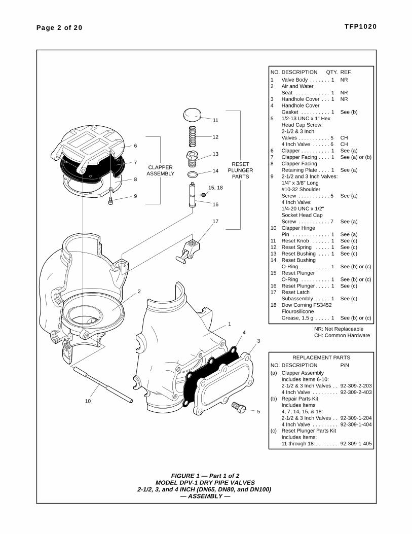
Components of the DPV-1 Valves areshown in Figure 1. The Body andHandhole Cover are ductile iron. TheHandhole Cover Gasket is neoprene,and the Clapper Facing is EPDM. The
Air/Water Seat Ring is brass, the Clap-per is bronze or aluminum bronze, andboth the Clapper Retaining Plate andLatch are bronze. The Hinge Pin isaluminum bronze, and the fastenersfor the Handhole Cover are carbonsteel.
Valve Trim:Installation dimensions are given inFigure 7, and the Valve Trim is illus-trated in Figures 4, 5, and 6. The ValveTrim forms a part of the laboratorylistings and approval of the DPV-1Valve and is necessary for the properoperation of the DPV-1 Valve. Eachpackage of trim includes the followingitems:
• Water Supply Pressure Gauge
• System Air Pressure Gauge
• Air Supply Connections
• Main Drain Valve
• Low Body Drain Valve
• Alarm Test Valve
• Automatic Drain Valve
• Drip Funnel
• Connections For Optional QuickOpening Device (Accelerator)
NOTEWhen the system pressure is greaterthan 175 psi (12,1 bar), provision is tobe made to replace the standard order300 psi (20,7 bar) Water Pressuregauge with a separately ordered 600psi (41,4 bar) Water Pressure Gauge.
Air Supply:Table B shows the system air pressurerequirements as a function of the watersupply pressure. The air (or nitrogen)pressure in the sprinkler system is rec-
ommended to be automatically main-tained by using one of the followingpressure maintenance devices, as ap-propriate:
• Model AMD-1 Air Maintenance De-vice (pressure reducing type).
• Model AMD-2 Air Maintenance De-vice (compressor control type).
• Model AMD-3 Nitrogen Mainte-nance Device (high pressure reduc-ing type).
The Pressure Relief Valve providedwith the valve trim is factory set torelieve at a pressure of approxi-mately 45 psi (3,1 bar). If the normalsystem air pressure is less than orexceeds 40 psi (2,8 bar), then thepressure Relief Valve must be reset torelieve at a pressure that is in accord-ance with the Authority Having Juris-diction.
Quick Opening Device:
As an option, the Model DPV-1 DryPipe Valve may be equipped with theModel QRS Electronic Dry Pipe ValveAccelerator (4 and 6 inch sizes) asdetailed in Technical Data SheetTFP1100 or the Model ACC-1 Me-chanical Dry Pipe Valve Accelerator(2-1/2, 3, 4, and 6 inch sizes) as de-tailed in Technical Data SheetTFP1112.
The QRS or the ACC-1 is used to re-duce the time to valve actuation fol-lowing the operation of one or moreautomatic sprinklers. In some casesthe use of a quick opening device suchas the QRS or the ACC-1 may be re-quired to meet the requirements of theNational Fire Protection Association tomeet water delivery times.
Patents:U.S.A. Patent No. 6,557,645
Page 4 of 20 TFP1020
ANSI B16.1 AS 2129JIS B 2210(Class 125) (Table E)(10K)
A7.50
9.50(190,5)
(241,3)
B0.75
0.88(19,0)
(22,2)
7.00
9.25(178,0)
(235,0)
0.71
0.87(18,0)
(22,0)
6.89(175,0)
Flange Drilling SpecificationNominal Dimensions in Inches and (mm)
9.45(240,0)
Valve
4 Inch
6 Inch(DN100)
(DN150)
N
8
8
ISO 7005-2(PN16)
7.09
9.45(180,0)
(240,0)
A B N
8
8
A B N
8
8
A B N
8
8
Dim. Dim.
Nominal
Qty. Dim. Dim. Qty. Dim. Dim. Qty. Dim. Dim. Qty.
Same drilling as for BS 4504 Section 3.2 (PN16) and DIN 2532 (PN16).Dim. A
Bolt CircleDiameter
Dim. BBolt HoleDiameter
Qty. NNumber ofBolt Holes
2
2
Size
Same drilling as for ANSI B16.5 (Class 150) and ANSI B16.42 (Class 150).1
1
0.75(19,0)0.91(23,0)
0.75(19,0)
0.59(15,0)
TABLE ADIMENSIONAL SPECIFICATIONS
FOR SELECTION OF FLANGE DRILLING
Page 5 of 20TFP1020
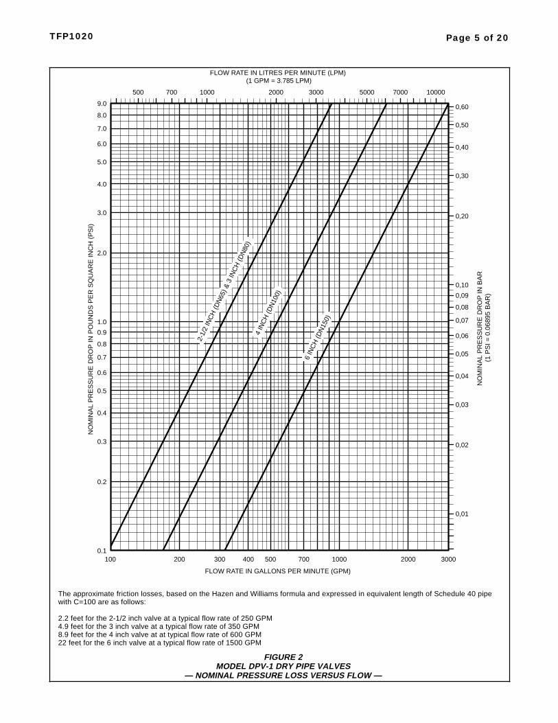
FIGURE 2MODEL DPV-1 DRY PIPE VALVES
— NOMINAL PRESSURE LOSS VERSUS FLOW —
The approximate friction losses, based on the Hazen and Williams formula and expressed in equivalent length of Schedule 40 pipewith C=100 are as follows:
2.2 feet for the 2-1/2 inch valve at a typical flow rate of 250 GPM4.9 feet for the 3 inch valve at a typical flow rate of 350 GPM8.9 feet for the 4 inch valve at at typical flow rate of 600 GPM22 feet for the 6 inch valve at a typical flow rate of 1500 GPM
2000 3000 5000 100007000
0,08
0,03
0,04
0,06
0,05
0,07
0,09
0,10
0,20
0,30
0,40
0,50
0,60
500 700 1000
300 700500400 1000 2000 3000
0.4
0.3
NO
MIN
AL
PR
ES
SU
RE
DR
OP
INP
OU
ND
SP
ER
SQ
UA
RE
INC
H(P
SI)
0.9
1.0
0.8
0.7
0.5
0.6
2.0
6.0
5.0
3.0
4.0
9.0
8.0
7.0
0.2
0.1200100
0,02
0,01
FLOW RATE IN GALLONS PER MINUTE (GPM)
FLOW RATE IN LITRES PER MINUTE (LPM)(1 GPM = 3.785 LPM)
(1P
SI=
0.0
6895
BA
R)
NO
MIN
AL
PR
ES
SU
RE
DR
OP
INB
AR
2-1/
2IN
CH
(DN
65) &
3IN
CH
(DN
80)
4 IN
CH
(DN
100)
6 IN
CH
(DN
150)
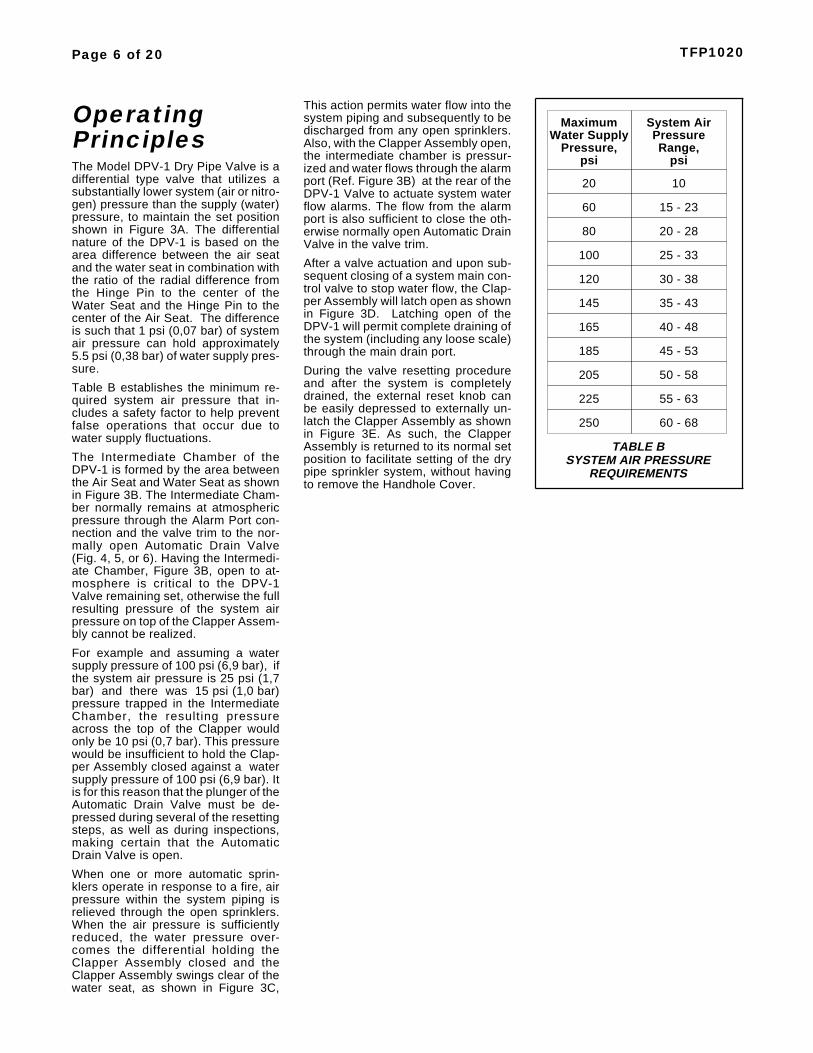
OperatingPrinciplesThe Model DPV-1 Dry Pipe Valve is adifferential type valve that utilizes asubstantially lower system (air or nitro-gen) pressure than the supply (water)pressure, to maintain the set positionshown in Figure 3A. The differentialnature of the DPV-1 is based on thearea difference between the air seatand the water seat in combination withthe ratio of the radial difference fromthe Hinge Pin to the center of theWater Seat and the Hinge Pin to thecenter of the Air Seat. The differenceis such that 1 psi (0,07 bar) of systemair pressure can hold approximately5.5 psi (0,38 bar) of water supply pres-sure.
Table B establishes the minimum re-quired system air pressure that in-cludes a safety factor to help preventfalse operations that occur due towater supply fluctuations.
The Intermediate Chamber of theDPV-1 is formed by the area betweenthe Air Seat and Water Seat as shownin Figure 3B. The Intermediate Cham-ber normally remains at atmosphericpressure through the Alarm Port con-nection and the valve trim to the nor-mally open Automatic Drain Valve(Fig. 4, 5, or 6). Having the Intermedi-ate Chamber, Figure 3B, open to at-mosphere is critical to the DPV-1Valve remaining set, otherwise the fullresulting pressure of the system airpressure on top of the Clapper Assem-bly cannot be realized.
For example and assuming a watersupply pressure of 100 psi (6,9 bar), ifthe system air pressure is 25 psi (1,7bar) and there was 15 psi (1,0 bar)pressure trapped in the IntermediateChamber, the resulting pressureacross the top of the Clapper wouldonly be 10 psi (0,7 bar). This pressurewould be insufficient to hold the Clap-per Assembly closed against a watersupply pressure of 100 psi (6,9 bar). Itis for this reason that the plunger of theAutomatic Drain Valve must be de-pressed during several of the resettingsteps, as well as during inspections,making certain that the AutomaticDrain Valve is open.
When one or more automatic sprin-klers operate in response to a fire, airpressure within the system piping isrelieved through the open sprinklers.When the air pressure is sufficientlyreduced, the water pressure over-comes the differential holding theClapper Assembly closed and theClapper Assembly swings clear of thewater seat, as shown in Figure 3C,
This action permits water flow into thesystem piping and subsequently to bedischarged from any open sprinklers.Also, with the Clapper Assembly open,the intermediate chamber is pressur-ized and water flows through the alarmport (Ref. Figure 3B) at the rear of theDPV-1 Valve to actuate system waterflow alarms. The flow from the alarmport is also sufficient to close the oth-erwise normally open Automatic DrainValve in the valve trim.
After a valve actuation and upon sub-sequent closing of a system main con-trol valve to stop water flow, the Clap-per Assembly will latch open as shownin Figure 3D. Latching open of theDPV-1 will permit complete draining ofthe system (including any loose scale)through the main drain port.
During the valve resetting procedureand after the system is completelydrained, the external reset knob canbe easily depressed to externally un-latch the Clapper Assembly as shownin Figure 3E. As such, the ClapperAssembly is returned to its normal setposition to facilitate setting of the drypipe sprinkler system, without havingto remove the Handhole Cover.
Page 6 of 20 TFP1020
MaximumWater Supply
Pressure,psi
System AirPressureRange,
psi
20
60
80
100
120
145
10
15 - 23
20 - 28
25 - 33
30 - 38
35 - 43
165
185
205
40 - 48
45 - 53
50 - 58
225 55 - 63
250 60 - 68
TABLE BSYSTEM AIR PRESSURE
REQUIREMENTS
Page 7 of 20TFP1020
FIGURE 3 — Part 1 of 2MODEL DPV-1 DRY PIPE VALVES
2-1/2, 3, and 4 INCH (DN65, DN80, and DN100)— SET AND OPEN POSITIONS —
INTERMEDIATECHAMBER
FULLY OPENASSEMBLYCLAPPER
& ALARM
FIGURE 3D
FIGURE 3A
DRAIN POSITION
SET POSITION
SHUT OFFWATER SUPPLY
FROM
SYSTEM
WATER SUPPLY
OPEN
3/4" NPTLOW BODY
DRAIN
04
ASSEMBLYLATCHED
CLAPPER
TEST PORT
02
LATCHCLAPPER
05
RESET
SET POSITIONFIGURE 3B
AIR PRESSURETO SYSTEM
1" NPT
PORT
1/2" NPTWATER
AIR SUPPLY
PRESSURESUPPLY
01
RESEATEDASSEMBLYCLAPPER
TO ALARM
ALARM PORTWATERFLOW
LATCH
FIGURE 3ERESET POSITION
SHUT OFFWATER SUPPLY
ASSEMBLYCLAPPER
PIVOTS TOUNLATCH
FIGURE 3COPERATED POSITION
COMPLETESYSTEM
WATER SUPPLY
CLAPPER
FROM
WATERFLOWTO SYSTEM
CLAPPER LATCH
CLAPPER ASSEMBLYPIVOTS TO ALLOW
TO FULLY OPEN
ASSEMBLY
ATMOSPHERE
3/4" NPT ALARMPORT OPEN TO
03
PORT
KNOBRESET
DRAIN FROMDRAIN FROM
CLAPPER
IN SETASSEMBLY
POSITION
PUSH HERE
VALVETO RESET
INTERMEDIATE
WATER
VALVEWATERWAY
SEAT
ASSEMBLYCLAPPER
PORT
CHAMBER
ALARM
AIRSEAT
03
& 3 INCH VALVES)1-1/4" NPT* (2-1/2 INCH
2" NPT (4 INCH VALVE)
MAIN DRAIN PORT:
DN40 FOR VALVES WITHISO THREADED PORTS
*
Page 8 of 20 TFP1020
FIGURE 3 — Part 2 of 2MODEL DPV-1 DRY PIPE VALVES
6 INCH (DN150)— SET AND OPEN POSITIONS —
ATMOSPHEREPORT OPEN TO3/4" NPT ALARM
TO FULLY OPEN
PIVOTS TO ALLOWCLAPPER ASSEMBLY
CLAPPER LATCH
TEST PORT
PRESSURE
FULLY OPENASSEMBLY
WATER SUPPLY
AIRSEAT
VALVEWATERWAY
LATCHCLAPPER
ASSEMBLYCLAPPERUNLATCH
PIVOTS TO
FROM
DRAIN
FIGURE 3ASET POSITION
WATER SUPPLY
FROM SYSTEM
SHUT OFF
FIGURE 3DDRAIN POSITION
WATER SUPPLY
PORT
2" NPT
PORTMAIN DRAIN
05
04
3/4" NPT
DRAIN
OPEN
LOW BODY
ASSEMBLYLATCHED
CLAPPER
LATCHCLAPPER
INTERMEDIATECHAMBER
WATERSEAT
CHAMBER
RESET
FIGURE 3BSET POSITIONINTERMEDIATE
ASSEMBLY
ASSEMBLYCLAPPER
TO SYSTEMAIR PRESSURE
1" NPT
PORTAIR SUPPLY
IN SETASSEMBLYCLAPPER
POSITION
01
02
03
& ALARM
1/2" NPT
CLAPPER
TO ALARM
TO RESETVALVE
PUSH HERE
WATERFLOW
CLAPPER
RESEATEDASSEMBLY
FIGURE 3ERESET POSITION
SHUT OFFWATER SUPPLY
FROM
SYSTEM
FIGURE 3C
DRAIN FROM
COMPLETE
OPERATED POSITION
WATER SUPPLY
ALARMPORT
03
RESETKNOB
ALARM PORT
WATERFLOWTO SYSTEM
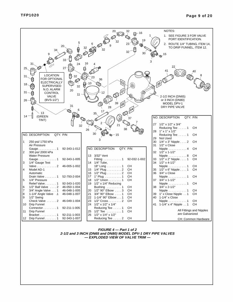
Page 9 of 20TFP1020
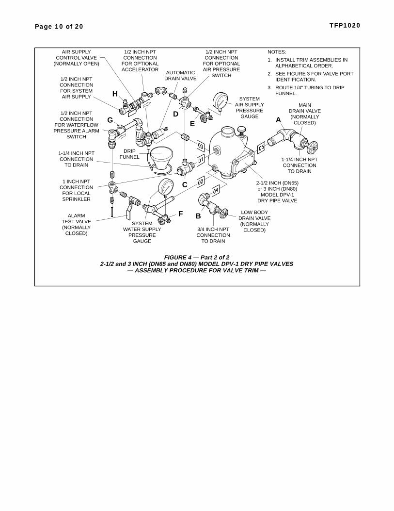
FIGURE 4 — Part 1 of 22-1/2 and 3 INCH (DN65 and DN80) MODEL DPV-1 DRY PIPE VALVES
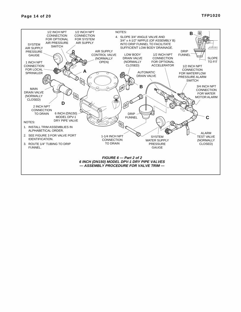
FIGURE 6 — Part 2 of 26 INCH (DN150) MODEL DPV-1 DRY PIPE VALVES— ASSEMBLY PROCEDURE FOR VALVE TRIM —
NOTES:
SEE FIGURE 3 FOR VALVE PORTIDENTIFICATION.
INSTALL TRIM ASSEMBLIES INALPHABETICAL ORDER.
SLOPE 3/4" ANGLE VALVE AND3/4" x 4-1/2" NIPPLE (OF ASSEMBLY B)INTO DRIP FUNNEL TO FACILITATESUFFICIENT LOW BODY DRAINAGE.
TEST VALVEALARM
(NORMALLYCLOSED)
DRAIN VALVE
2 INCH NPTCONNECTION
AIR SUPPLYCONTROL VALVE
(NORMALLYOPEN)
1/2 INCH NPTCONNECTIONFOR SYSTEMAIR SUPPLY
TO DRAIN
PRESSUREGAUGE
AIR SUPPLYSYSTEM
1-1/4 INCH NPTCONNECTION
TO DRAIN
DRAIN VALVELOW BODY
(NORMALLYCLOSED)
1 INCH NPTCONNECTIONFOR LOCALSPRINKLER
PRESSUREGAUGE
WATER SUPPLYSYSTEM
1/2 INCH NPTCONNECTION
FOR OPTIONALACCELERATOR
3/4 INCH NPTCONNECTIONFOR WATER
MOTOR ALARM
1/2 INCH NPTCONNECTION
FOR WATERFLOWPRESSURE ALARM
SWITCH
MAIN
(NORMALLYCLOSED)
A
D
B
C
TO FITSLOPE
B
FUNNELDRIP
NOTES:
2.
1.
4.
FUNNELDRIP
AUTOMATICDRAIN VALVE
ROUTE 1/4" TUBING TO DRIPFUNNEL.
3.
6 INCH (DN150)MODEL DPV-1
DRY PIPE VALVE
1/2 INCH NPTCONNECTION
FOR OPTIONALAIR PRESSURE
SWITCH
Page 15 of 20TFP1020
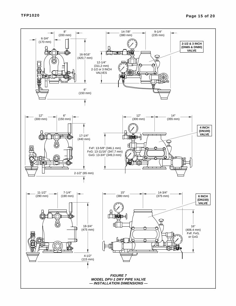
FIGURE 7MODEL DPV-1 DRY PIPE VALVE
— INSTALLATION DIMENSIONS —
16-9/16"(420,7 mm)
6"(150 mm)
(311,2 mm)2-1/2 or 3 INCH
14-7/8"(380 mm)
9-1/4"(235 mm)
6-3/4"(170 mm)
8"(200 mm)
12-1/4"
VALVES
2-1/2 & 3 INCH(DN65 & DN80)
VALVE
6"(150 mm)
17-1/4"(440 mm)
2-1/2" (65 mm)
12"(300 mm)
14"(355 mm)
12"(300 mm)
FxF: 13-5/8" (346,1 mm)
GxG: 13-3/4" (349,3 mm)FxG: 13-11/16" (347,7 mm)
4 INCH(DN100)VALVE
7-1/4"(190 mm)
18-3/4"(475 mm)
4-1/2"
11-1/2"(290 mm)
14-3/4"(375 mm)
15"(380 mm)
(115 mm)
16"
FxF, FxG,(406.4 mm)
or GxG
6 INCH(DN150)VALVE
InstallationNOTES
Proper operation of the Model DPV-1Dry Pipe Valve depends upon its trimbeing installed in accordance with theinstructions given in this TechnicalData Sheet. Failure to follow the ap-propriate trim diagram may preventthe DPV-1 Valve from functioningproperly, as well as void listings, ap-provals, and the manufacturer’s war-ranties.
Failure to latch open the Clapper As-sembly prior to a system hydrostatictest may result in damage to the Clap-per Assembly.
The DPV-1 Valve must be installed ina readily visible and accessible loca-tion.
The DPV-1 Valve and associated trimmust be maintained at a minimum tem-perature of 40°F/4°C.
Heat tracing of the DPV-1 Valve or itsassociated trim is not permitted. Heattracing can result in the formation ofhardened mineral deposits that are ca-pable of preventing proper operation.
The Model DPV-1 Dry Pipe Valve is tobe installed in accordance with the fol-lowing criteria:
Step 1. All nipples, fittings, and de-vices must be clean and free of scaleand burrs before installation. Use pipethread sealant sparingly on male pipethreads only.
Step 2. The DPV-1 Valve must betrimmed in accordance with Figures 4,5, or 6, as applicable. If the DPV-1 isto be equipped with a Dry Pipe ValveAccelerator, refer to the TechnicalData Sheet TFP1100 for the ModelQRS Electronic Dry Pipe Valve Accel-erator or TFP1112 for the Model ACC-1 Mechanical Dry Pipe Valve Accel-erator.
Step 3. Care must be taken to makesure that check valves, strainers,globe valves, etc. are installed with theflow arrows in the proper direction.
Step 4. Drain tubing to the drip funnelmust be installed with smooth bendsthat will not restrict flow.
Step 5. The main drain and drip funneldrain may be interconnected provideda check valve is located at least 12inches (300 mm) below the drip funnel.The Low Body Drain Valve (Fig. 4, 5,or 6) may be piped so as to dischargeinto the Drip Funnel or to a separatedrain.
Step 6. Suitable provision must bemade for disposal of drain water.Drainage water must be directed such
that it will not cause accidental dam-age to property or danger to persons.
Step 7. Unused pressure alarm switchand/or water motor alarm connectionsmust be plugged.
Step 8. The Pressure Relief Valve pro-vided with the Valve Trim is factory setto relieve at a pressure of approxi-mately 45 psi (3,1 bar), which can typi-cally be used for a maximum normalsystem air pressure of 40 psi (2,8 bar).The Pressure Relief Valve may be re-set to a lower or higher pressure; how-ever, it must be be reset to relieve at apressure which is in accordance withthe requirements of the Authority Hav-ing Jurisdiction.
To reset the Pressure Relief Valve,first loosen the jam nut and then adjustthe cap accordingly — clockwise for ahigher pressure setting or counter-clockwise for a lower pressure setting.After verifying the desired pressuresetting, tighten the jam nut.
Step 9. Installation of an Air Mainte-nance Device, as described in theTechnical Data Section, is recom-mended.
Step 10. An Inspector’s Test Connec-tion as required By NFPA 13 must beprovided on the system piping at themost remote location from the ModelDPV-1 Valve.
Step 11. Conduit and electrical con-nections are to be made in accordancewith the requirements of the authorityhaving jurisdiction and/or the NationalElectric Code.
Step 12. Before a system hydrostatictest is performed in accordance withNFPA 13 system acceptance test re-quirements, the Clapper Assembly isto be manually latched open (Ref. Fig.3D); the Automatic Drain Valve (Fig. 4,5, or 6) is to be temporarily replacedwith a 1/2 inch NPT plug, the 3/32 inchVent Fitting (Item 13, Fig. 4; Item 15,Fig. 5; or Item 15, Fig. 6) is to betemporarily replaced with a 1/4 inchNPT plug, and the Handhole CoverBolts are to be tightened using a cross-draw sequence.
Valve SettingProcedureSteps 1 through 11 are to be per-formed when initially setting the ModelDPV-1 Dry Pipe Valve; after an opera-tional test of the fire protection system;or, after system operation due to a fire.
NOTESIf the DPV-1 is equipped with a DryPipe Valve Accelerator, refer to its re-setting instructions before resettingthe DPV-1. Refer to TFP1100 for theQRS or TFP1112 for the ACC-1.
Based on the instructions provided, re-set the Accelerator at the appropriatetime during the resetting of the DPV-1.
Step 1. Close the Main Control Valve,and close the Air Supply Control Valve(Fig. 4, 5, or 6). If the DPV-1 isequipped with a Dry Pipe Valve Accel-erator, remove the Dry Pipe Valve Ac-celerator from service in accordancewith its Technical Data Sheet (Refer toTFP1100 for the QRS or TFP1112 forthe ACC-1).
Step 2. Open the Main Drain Valve(Fig. 4, 5, or 6) and all auxiliary drainsin the system. Close the auxiliary drainvalves after water ceases to dis-charge. Leave the Main Drain Valveopen.
Step 3. Depress the plunger of theAutomatic Drain Valve (Fig. 4, 5, or 6)to verify that it is open and that theDPV-1 Valve is completely drained.
Step 4. Open the Optional Alarm Con-trol Valve (Fig. 4, 5, or 6), as applica-ble, if it was closed to silence localalarms.
Step 5. As necessary, replace allsprinklers that have operated. Re-placement sprinklers must be of thesame type and temperature rating asthose which have operated.
NOTEIn order to prevent the possibility of asubsequent operation of an over-heated solder type sprinkler, any sol-der type sprinklers which were possi-bly exposed to a temperature greaterthan their maximum rated ambientmust be replaced.
Step 6. Push down on the Reset Knob(Fig. 3E) to allow the Clapper Assem-bly to reseat.
Step 7. Pressurize the system with air(or nitrogen) to 10 psi (0,7 bar), andthen individually open all auxiliarydrain valves in the system piping todrain any remaining water in trappedsections. Close each drain valve assoon as water ceases to discharge.
Page 16 of 20 TFP1020
Also partially open the Low Body DrainValve (Fig. 4, 5, or 6) to assure that theriser is completely drained. Close theLow Body Drain Valve as soon aswater ceases to discharge.
Step 8. Refer to Table B and thenrestore the system to the normal sys-tem air pressure as necessary to holdthe DPV-1 Valve closed.
Step 9. Depress the plunger on theAutomatic Drain Valve to make sure itis open and that there is no air dis-charging.
The absence of air discharging fromthe Automatic Drain Valve is an indica-tion of a properly set air seat within theDPV-1 Valve. If air is discharging, referto the Care and Maintenance sectionunder Automatic Drain Valve Inspec-tion to determine/correct the cause ofthe leakage problem.
Step 10. Partially open the Main Con-trol Valve. Slowly close the Main DrainValve as soon as water dischargesfrom the drain connection.
Depress the plunger on the AutomaticDrain Valve to make sure that it is openand that there is no water discharging.The absence of water dischargingfrom the Automatic Drain Valve is anindication of a properly set water seatwithin the DPV-1 Valve. If water is dis-charging, refer to the Care and Main-tenance section under the AutomaticDrain Valve Inspection to deter-mine/correct the cause of the leakageproblem.
If there are no leaks, the DPV-1 Valveis ready to be placed in service and theMain Control Valve must then be fullyopened.
NOTEAfter setting a fire protection system,notify the proper authorities and ad-vise those responsible for monitoringproprietary and/or central stationalarms.
Step 11. Once a week after a valve isreset following an operational test orsystem operation, the Low Body DrainValve (and any low point drain valves)should be partially opened (and thensubsequently closed) to relieve drain-back water. Continue this procedureuntil drain-back water is no longer pre-sent.
Care andMaintenanceThe following procedures and inspec-tions should be performed as indi-cated, in addition to any specific re-quirements of the NFPA, and anyimpairment must be immediately cor-rected.
The owner is responsible for the in-spection, testing, and maintenance oftheir fire protection system and de-vices in compliance with this docu-ment, as well as with the applicablestandards of the National Fire Protec-tion Association (e.g., NFPA 25), inaddition to the standards of anyauthority having jurisdiction. The in-stalling contractor or product manufac-turer should be contacted relative toany questions.
It is recommended that automaticsprinkler systems be inspected,tested, and maintained by a qualifiedInspection Service.
NOTESThe operational test procedure andwaterflow pressure alarm test proce-dure will result in operation of the as-sociated alarms. Consequently, notifi-cation must first be given to the ownerand the fire department, central sta-tion, or other signal station to which thealarms are connected.
Before closing a fire protection systemmain control valve for maintenancework on the fire protection system thatit controls, permission to shut down theaffected fire protection systems mustfirst be obtained from the properauthorities and all personnel who maybe affected by this decision must benotified.
Annual Operation Test ProcedureProper operation of the DPV-1 Valve(i.e., opening of the DPV-1 Valve dur-ing a fire condition) should be verifiedat least once a year as follows:
Step 1. If water must be preventedfrom flowing beyond the riser, performthe following steps.
• Close the Main Control Valve.
• Open the Main Drain Valve.
• Open the Main Control Valve oneturn beyond the position at whichwater just begins to flow from theMain Drain Valve.
• Close the Main Drain Valve.
Step 2. Open the system’s Inspector’sTest Connection.
Step 3. Verify that the DPV-1 Valve
has operated, as indicated by the flowof water into the system and that allwaterflow alarms operate properly.
Step 4. Close the system’s Main Con-trol Valve.
Step 5. Reset the DPV-1 Valve in ac-cordance with the Valve Setting Proce-dure.
NOTEIt is recommended that the require-ment of NFPA 25 to annually inspectthe inside of the valve be performed atthis time and prior to resetting theDPV-1 Valve. Refer to the AutomaticDrain Valve Inspection sub-sectionSteps 2 through 5 for instructions withregard to the inspection of the ClapperFacing.
Quarterly Waterflow Alarm TestProcedureTesting of the system waterflowalarms should be performed quarterly.To test the waterflow alarm, open theAlarm Test Valve, which will allow aflow of water to the Waterflow Pres-sure Alarm Switch and/or Water MotorAlarm. Upon satisfactory completionof the test, close the Alarm Test Valve.
Water Pressure InspectionThe Water Pressure Gauge is to beinspected monthly (per NFPA 25) toensure that normal system water pres-sure is being maintained.
Air Pressure InspectionThe Air Pressure Gauge is to be in-spected monthly (per NFPA 25) to en-sure that normal system air pressureis being maintained.
Automatic Drain Valve InspectionThe Automatic Drain Valve should beinspected monthly (per NFPA 25) bydepressing the plunger and checkingto ensure that the Automatic DrainValve is not discharging water and/orair. A discharge of water and/or air isan indication that the air and/or waterseats are leaking, which could sub-sequently cause a false operationshould the intermediate chamber be-come inadvertently pressurized.
If leakage is present, take the DPV-1Valve out of service (i.e., close themain control valve, open the maindrain valve, close the air supply controlvalve, remove the Dry Pipe Valve Ac-celerator from service, as applicable,in accordance with its Technical DataSheet (Refer to TFP1100 for the QRSor TFP1112 for the ACC-1), and openthe Inspector’s Test Connection to re-lieve the system air pressure to 0 psigas indicated on the System Air Pres-sure Gauge), and then after removing
Page 17 of 20TFP1020
the Handhole Cover, perform the fol-lowing steps:
Step 1. Make sure that the Seat Ringis clean and free of any nicks or signifi-cant scratches.
Step 2. Remove the Clapper Assem-bly from the valve by first pulling outthe Hinge Pin.
Step 3. Disassemble the Clapper Fac-ing Retainer from the Clapper so thatthe Clapper Facing can be removedand inspected. Make sure that theClapper Facing does not show signs ofcompression set, damage, etc. Re-place the Clapper Facing if there is anysigns of wear.
Step 4. Clean the Clapper Facing,Clapper, and Clapper Facing Retainer,and then reassemble the Clapper As-sembly.
Step 5. Reinstall the Clapper Assem-bly with its Hinge Pin and then reinstallthe Handhole Cover.
LimitedWarrantyProducts manufactured by Tyco Fire &Building Products (TFBP) are war-ranted solely to the original Buyer forten (10) years against defects in mate-rial and workmanship when paid forand properly installed and maintainedunder normal use and service. Thiswarranty will expire ten (10) yearsfrom date of shipment by TFBP. Nowarranty is given for products or com-ponents manufactured by companiesnot affiliated by ownership with TFBPor for products and components whichhave been subject to misuse, improperinstallation, corrosion, or which havenot been installed, maintained, modi-fied or repaired in accordance with ap-plicable Standards of the National FireProtection Association, and/or thestandards of any other AuthoritiesHaving Jurisdiction. Materials foundby TFBP to be defective shall be eitherrepaired or replaced, at TFBP’s soleoption. TFBP neither assumes, norauthorizes any person to assume for it,any other obligation in connection withthe sale of products or parts of prod-ucts. TFBP shall not be responsible forsprinkler system design errors or inac-curate or incomplete information sup-plied by Buyer or Buyer’s repre-sentatives.
In no event shall TFBP be liable, incontract, tort, strict liability or underany other legal theory, for incidental,indirect, special or consequential dam-ages, including but not limited to laborcharges, regardless of whether TFBPwas informed about the possibility ofsuch damages, and in no event shallTFBP’s liability exceed an amountequal to the sales price.
The foregoing warranty is made in lieuof any and all other warranties, ex-press or implied, including warrantiesof merchantability and fitness for a par-ticular purpose.
This limited warranty sets forth the ex-clusive remedy for claims based onfailure of or defect in products, materi-als or components, whether the claimis made in contract, tort, strict liabilityor any other legal theory.
This warranty will apply to the full ex-tent permitted by law. The invalidity, inwhole or part, of any portion of thiswarranty will not affect the remainder.
Page 18 of 20 TFP1020
OrderingProcedure
NOTERefer to Table A for Flange DrillingSpecifications.
Part Numbers for factory pre-trimmedModel DPV-1 Valves are provided inthe Price Book.
Standard DPV-1 Dry Pipe Valve(American Standard FlangeDrilling, Threaded Ports, andGroove Outside Diameter, as appli-cable):Specify: (specify size) Model DPV-1Dry Pipe Valve with (specify inlet xoutlet) end connections, P/N (specify).
2-1/2 Inch (DN65)
G x G,2.88 inch (73,1mm) O.D.Groove x 2.88inch (73,1 mm)O.D. Groove . . . . . . . . . . . P/N 52-310-1-925
3 Inch (DN80)
G x G,3.50 inch (88,9mm) O.D.Groove x 3.50inch (88,9 mm)O.D. Groove . . . . . . . . . . . P/N 52-310-1-930
4 Inch (DN100)
G x G,4.50 inch (114,3mm) O.D.Groove x 4.50inch (114,3 mm)O.D. Groove . . . . . . . . . . . P/N 52-310-1-940
F x G,ANSI DrilledFlange x 4.50inch (114,3 mm)O.D. Groove . . . . . . . . . . . P/N 52-310-1-440
F x F,ANSI DrilledFlange x ANSIDrilled Flanged . . . . . . . . . P/N 52-310-1-040
6 Inch (DN150)
G x G,6.62 inch (168,3mm) O.D.Groove x 6.62inch (168,3 mm)O.D. Groove . . . . . . . . . . . P/N 52-310-1-960
F x G,ANSI DrilledFlange x 6.62inch (168,3 mm)O.D. Groove . . . . . . . . . . . P/N 52-310-1-460
F x F,ANSI DrilledFlange x ANSIDrilled Flanged . . . . . . . . . P/N 52-310-1-060
Standard Galvanized DPV-1 Trim(Ref. Figure F):Specify: 2-1/2 and 3 Inch DPV-1 Semi-Preassembled Galvanized Trim,P/N 52-309-2-005.
Specify: 4 Inch DPV-1 Semi-Preas-sembled Galvanized Trim,P/N 52-309-2-001.
Specify: 6 Inch DPV-1 Semi-Preas-sembled Galvanized Trim,P/N 52-309-2-002.
Optional Accelerator:
Model QRS ElectronicAccelerator(Details provided in TFP1100)
Specify: Model QRS Electronic DryPipe Valve Accelerator Package,P/N 52-312-2-101.
Model ACC-1 MechanicalAccelerator(Details provided in TFP1112)
Specify: Model ACC-1 Dry Pipe Ac-celerator, P/N 52-311-1-001, and
Galvanized Accelerator Trim forModel DPV-1 Dry Pipe Valve,P/N 52-311-2-010.
Optional 600 PSI Water PressureGauge:
Specify: 600 PSI Water PressureGauge, P/N 92-343-1-004.
Accessories:Order the Technical Data Sheets forthe following, as applicable, for detailsand additional accessories:
4 Inch (DN100)Model DPV-1G x G Dry Pipe Valve . . . . . . . . . 57 lbs. (26 kg)
4 Inch (DN100)Model DPV-1F x G Dry Pipe Valve . . . . . . . . . . 67 lbs. (31 kg)
4 Inch (DN100)Model DPV-1F x F Dry Pipe Valve . . . . . . . . . . 77 lbs. (36 kg)
4 Inch (DN100) Valve Trim . . . . . . 30 lbs. (14 kg)
6 Inch (DN150)Model DPV-1G x G Dry Pipe Valve. . . . . . . . . . 95 lbs. (44 kg)
6 Inch (DN150)Model DPV-1F x G Dry Pipe Valve . . . . . . . . . . 108 lbs. (50 kg)
6 Inch (DN150)Model DPV-1F x F Dry Pipe Valve . . . . . . . . . . 121 lbs. (56 kg)
6 Inch (DN150) Valve Trim . . . . . . 30 lbs. (14 kg)
Other DPV-1 Dry Pipe Valves:
NOTESOther DPV-1 Dry Pipe Valves arevalves ordered with a any combinationof flange, threaded ports, or grooveoutside diameter not offered under“Standard DPV-1 Dry Pipe Valve” of-ferings.
Valves with NPT threaded ports areintended for use with the “StandardGalvanized DPV-1 Valve Trim” offeredand detailed in this document. Valveswith ISO threaded ports are intendedfor use with special order trim that isprovided by local distributors to meetthe specific needs of certain localities.Please contact your local distributorregarding valves and valve trim forspecific localities.
Specify: (specify size) Model DPV-1Dry Pipe Valve with (specify inlet xoutlet) connections with (specify NPTor ISO) threaded ports, P/N (specify).
Page 19 of 20TFP1020
Page 20 of 20 TFP1020
TYCO FIRE & BUILDING PRODUCTS, 451 North Cannon Avenue, Lansdale, Pennsylvania 19446
Part Numbers For Other4 Inch (DN100) Dry Pipe Valves: