Model-Driven and Pattern-Based Integration of Process-Driven SOA Models
Uwe Zdun and Schahram Dustdar
Distributed Systems Group
Information Systems Institute
Austria
{zdun|dustdar}@infosys.tuwien.ac.at
Abstract
Service-oriented architectures (SOA) are increasingly used in the context of business processes. However, the
modeling approaches for process-driven SOAs do not yet sufficiently integrate the various kinds of models relevant
for a process-driven SOA – ranging from process models to software architectural models to software design models.
We propose to integrate process-driven SOA models via a model-driven software development approach that is based
on proven practices documented as software patterns. We introduce pattern primitives as an intermediate abstraction
to formally model the participants in the solutions that patterns convey. To enable model-driven development, we
develop domain-specific modeling languages for each kind ofprocess-driven SOA model – based on formal meta-
models that are extended with the pattern primitives. The various process-driven SOA models are integrated in a
model-driven tool chain via the meta-models. Our tool chainvalidates the process-driven SOA models with regard
to the constraints given by the meta-models and primitives.
1 Introduction
Many service-oriented architectures (SOA) provide a Service Composition Layer that introduces a process engine
(or workflow engine) as the top-level layer [35]. Services realize individual activities in the process (aka process
steps, tasks in the process). This kind of architecture is called process-driven SOA. The main goal of process-driven
SOAs is to increase the productivity, efficiency, and flexibility of an organization. This is achieved by aligning the
high-level business processes with the technical IT services. That is, the business goals get closer integrated with
the IT architecture. Organizational flexibility can be achieved because explicit business process models are easier to
change and evolve than for instance business processes thatare hard-coded in the program code. In the long run the
goal is to enable business process improvement through IT.
1Dagstuhl Seminar Proceedings 06291The Role of Business Processes in Service Oriented Architectureshttp://drops.dagstuhl.de/opus/volltexte/2006/820
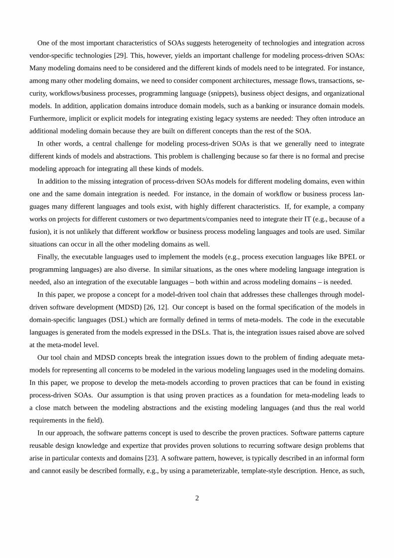
One of the most important characteristics of SOAs suggests heterogeneity of technologies and integration across
vendor-specific technologies [29]. This, however, yields an important challenge for modeling process-driven SOAs:
Many modeling domains need to be considered and the different kinds of models need to be integrated. For instance,
among many other modeling domains, we need to consider component architectures, message flows, transactions, se-
curity, workflows/business processes, programming language (snippets), business object designs, and organizational
models. In addition, application domains introduce domainmodels, such as a banking or insurance domain models.
Furthermore, implicit or explicit models for integrating existing legacy systems are needed: They often introduce an
additional modeling domain because they are built on different concepts than the rest of the SOA.
In other words, a central challenge for modeling process-driven SOAs is that we generally need to integrate
different kinds of models and abstractions. This problem ischallenging because so far there is no formal and precise
modeling approach for integrating all these kinds of models.
In addition to the missing integration of process-driven SOAs models for different modeling domains, even within
one and the same domain integration is needed. For instance,in the domain of workflow or business process lan-
guages many different languages and tools exist, with highly different characteristics. If, for example, a company
works on projects for different customers or two departments/companies need to integrate their IT (e.g., because of a
fusion), it is not unlikely that different workflow or business process modeling languages and tools are used. Similar
situations can occur in all the other modeling domains as well.
Finally, the executable languages used to implement the models (e.g., process execution languages like BPEL or
programming languages) are also diverse. In similar situations, as the ones where modeling language integration is
needed, also an integration of the executable languages – both within and across modeling domains – is needed.
In this paper, we propose a concept for a model-driven tool chain that addresses these challenges through model-
driven software development (MDSD) [26, 12]. Our concept isbased on the formal specification of the models in
domain-specific languages (DSL) which are formally defined in terms of meta-models. The code in the executable
languages is generated from the models expressed in the DSLs. That is, the integration issues raised above are solved
at the meta-model level.
Our tool chain and MDSD concepts break the integration issues down to the problem of finding adequate meta-
models for representing all concerns to be modeled in the various modeling languages used in the modeling domains.
In this paper, we propose to develop the meta-models according to proven practices that can be found in existing
process-driven SOAs. Our assumption is that using proven practices as a foundation for meta-modeling leads to
a close match between the modeling abstractions and the existing modeling languages (and thus the real world
requirements in the field).
In our approach, the software patterns concept is used to describe the proven practices. Software patterns capture
reusable design knowledge and expertize that provides proven solutions to recurring software design problems that
arise in particular contexts and domains [23]. A software pattern, however, is typically described in an informal form
and cannot easily be described formally, e.g., by using a parameterizable, template-style description. Hence, as such,
2
patterns are not usable in formal meta-models. We remedy this problem by introducing an intermediate abstraction,
called pattern primitives. A pattern primitive is a fundamental, formalizable modeling element in representing a
pattern.
Our general approach to apply pattern primitives for process-driven SOAs is to use one kind of formal modeling
language for all kinds of flow models that are used in a process-driven SOA – and extend it with additional modeling
concepts where necessary to connect to other kinds of models. The connection between the various kinds of models
and the validation of the models (with regard to model integrability and consistency in and across the modeling
domains) is the main task of our model-driven tool chain concepts. To demonstrate our approach, we will use a
formalizable subset of UML2 and OCL to develop one formal modeling language to depict the various refinements
of processes in process-driven SOA models, even though our approach in general is not depending on the use of the
UML.
In this paper, we first provide the background on MDSD and patterns/pattern primitives in Section 2 to lay out the
foundations of our approach. Next, in Section 3 we explain the concepts and architecture of our model-driven tool
chain to give an overview of our approach. In Section 4 we explain how we use meta-models to integrate process-
driven SOA models across modeling domains. Then in Section 5we explain the pattern primitives approach for
process-driven integration of services using flow abstractions as the primary modeling domain used in our approach
for modeling process-driven SOAs. In Section 6 we demonstrate how architectural abstractions – as one example of
another modeling domain – can be integrated with the flow abstraction models. We explain all primitive models with
running examples from a pattern language for process-driven integration of services, which we have implemented in
our MDSD tool chain to validate our approach. Finally, we discuss related work, evaluate our approach in comparison
to related work, and conclude.
2 Background
Before presenting our concepts for model-driven and pattern-based integration of process-driven SOA models, we
want to briefly explain the model-driven software development and software patterns concepts that we use as the
foundations for our approach.
2.1 Model-driven Software Development
Our approach to model-driven software development (MDSD) [26, 12] for process-driven SOAs is based on the
notion of domain-specific languages (DSL) for modeling the various types of models. Domain-specific languages
are “small” languages that are tailored to be particularly expressive in a certain problem domain. The DSL describes
knowledge via a graphical or textual syntax (referred to as the DSLs concrete syntax [12]), which is tied to domain-
specific modeling elements through a formal language meta-model (referred to as the DSLs abstract syntax [12]).
That is, the DSL elements are defined in terms of a meta-model that can be instantiated in concrete application
3
models. The application models are defined in the DSL’s concrete syntax, which represents the abstract syntax
defined in the meta-model.
In our approach, we use or introduce meta-models that are representing a modeling domain. The meta-models
presented in this paper are based on the UML2 meta-model (andextensions of it): For example we use UML2 activity
diagrams to model flow abstractions and UML2 class/component diagrams to model the object-oriented design and
architecture models. But any other meta-model can be used ina similar way. Examples for concrete syntaxes are a
graphical UML model or an XML file specifying a process model.
Application Model
DSLConcrete Syntax
Meta-Model(DSL Abstract Syntax )
Meta-Meta-Model
based on
defined in
based on
*
Transformation
1
*
1
represents
1
*
* 1
use defined using
**
Schematic Recurring Code
produces
*1..*
1..* 1..*
Individual Codeuses
* *
Figure 1. Relations of Artifacts in MDSD
Meta-models are defined in terms of a meta-meta-model. In UML, for instance, this is MOF. Most MDSD tools
support their own meta-meta-model, which basically represents a mapping from meta-model definitions to the imple-
mentation of the MDSD tool chain. Below, in the examples fromour prototype, we use a simple meta-meta-model to
define both the UML2 meta-model and pattern primitives extensions. It is not particularly important for our approach,
which meta-meta-model is used, there just must be some way toexpress the relationships between a meta-model and
the implementation code. The meta-meta-model is not visible to developers who build application models, but only
to those who build meta-models.
Each MDSD tool introduces some way to specify transformations. There are different kinds of transformations,
such as model-to-model transformations or model-to-code transformations. There are also different ways to specify
transformation, such as transformation rules, imperativetransformations, or template-based transformations. In any
case, the ultimate goal of all transformations in MDSD toolsis to generate code in executable languages, such as
programming languages or process execution languages. TheMDSD tools are used to generate all those parts of
the executable code which are schematic and recurring, and hence can be automated. Of course, some code must be
hand-written either because it is individual code for a system or the semantics of the code are not fully covered by the
DSLs (yet). The individual code and the generated code use each other and interact through well defined interfaces.
Figure 1 summarizes the relations of artifacts in MDSD. Thisshort introduction to the terms used in MDSD should
4
suffice for this paper. We will provide examples for the various concepts in the text below, as we use them. Please
refer to [26, 12] for a thorough introduction to the MDSD approach.
2.2 Software Patterns and Pattern Primitives
Software patterns and pattern languages have gained wide acceptance in the field of software development, because
they provide systematic reuse strategies for design knowledge [23]. Each pattern is a three-part rule, which expresses
a relation between a certain context, a problem, and a solution [3]. A pattern language is a collection of patterns that
solve the prevalent problems in a particular domain and context, and, as a language of patterns, it specifically focuses
on the pattern relationships in this domain and context.
Patterns informally describe many possible variants of onesoftware solution that a human developer or designer
can recognize as one and the same solution. A pattern encodesproven practices for particular, recurring design
decisions. A pattern language can thus be seen as a language of design decisions that one can follow in a number of
possible sequences. Hence, patterns encode recurring design decisions, give them a name that can be used throughout
a development team, allow development team members to tracethe design considerations in the design decisions by
following the sequences in the pattern language, etc.
Even though these properties of the pattern approach are highly valuable in the software design process, they also
make pattern instances hard to trace in the models and implementations. To overcome this problem, we introduced
an approach to document formalizable primitive abstractions that can be found in the patterns [34]. Documenting
pattern primitives means to find precisely describable modeling elements that are primitive in the sense that they
represent basic units of abstraction in the domain of the pattern. Our original pattern primitives concept presented
in [34] is only targeted at modeling architectural patterns. That is, in the architectural realm, basic architectural
abstractions like components, connectors, ports, and interfaces are used. An interesting challenge in describing the
pattern primitives for the patterns of process-driven SOA is that this area is characterized by the fact that we need
to understand various design and architecture concepts, aswell as various design and implementation languages, in
order to be able to model a process-driven SOA design fully. Also, other aspects like organizational roles must be
considered. This is an important difference to the area of general architectural patterns.
In this paper, we model pattern primitives using UML 2.0 extensions because the UML has become the “lingua
franca” of software design and is vastly supported by tools.We specify an extension of a UML 2.0 metaclass for
each elicited primitive, using the standard UML extension mechanisms: stereotypes, tag definitions, and constraints.
We use the Object Constraint Language (OCL) to formalize theconstraints and provide precise semantics to the
primitives.
3 Model-driven Tool Chain: Concepts and Architecture
In our concept, similar artifacts must be produced for each modeling domain. As many modeling domains need
to be considered to adequately model a process-driven SOA, we will first describe the general activities which must
5
be performed for each individual modeling domain – before a model-driven development of process-driven SOAs in
this modeling domain is possible. Next, we will give an overview of our integration concepts for integrating models
across modeling domains.
3.1 Model-driven Design Process
A model-driven design process, according to our approach, should loosely follow the activities described below.
Please note that our approach does not require any particular order of these activities.
1. Elicitation of input languages/models:In each modeling domain, there might be multiple input languages or
models which are needed for the process-driven SOA. For instance, if different UML tools are used, different
XMI exports of these tools must be considered for UML models.Another example is the area of business
process and workflow modeling languages, where a plethora oftools exists which use different standard and
non-standard process and workflow modeling languages. Eventhe same standard language might be inter-
preted differently by different tool vendors. Similar situations exist in other modeling domains. It is hence
important to elicit the relevant input languages/models, and maybe identify a sub-set of them to be reflected in
the DSLs. Please note that sometimes no external tool shouldbe used for modeling, but an inhouse develop-
ment or an external tool can be extended with export formats.Then it is possible to model directly in the DSL
(i.e., the DSL concrete syntax is the only input format for the modeling domain).
2. Elicitation of output languages (aka execution languages): Sometimes only one target execution language
should be used as an output for a particular modeling domain.But in other cases, the same models should
be used for generating code in different execution languages. For instance, if a company develops code for
different process engines (e.g., in different projects), different business process languages might be used as
execution languages by these engines or different dialectsof one language. A similar situation can also occur,
if different programming languages or platforms are to be supported.
3. Development or definition of an MDSD tool chain:There is a common workflow for model-driven code
generation following our approach: the input languages/models need to be read and transformed into DSLs
which are defined using meta-models. Then the DSL code shouldget validated according to the meta-models
and constraints defined on them. Finally, code in the target output languages should get generated. In between
many other steps are possible, such as model transformations. The generation tool chain must support a way to
define meta-models. It must also provide a constraint language to define structural constraints at the meta-level
(i.e., on meta-models). The tool chain needs to be extensible with input and output languages/models, e.g.,
via plugins. It must provide a means to flexibly assemble the generation workflow and the plugins. There are
many existing code generators that provide these features (an open source example is openArchitectureWare
[22]), but of course it is also possible to custom-build parts of the generation tool chain to realize the concepts.
In our prototype we use the language Frag [33, 32] for the definition of DSLs and meta-models, because it is
6
especially designed for this task. The language is also usedfor the implementation of the constraint language
and the model validator.
4. Definition of meta-models (abstract syntax of modeling DSL): For each DSL we need to define a meta-model
which describes the abstract syntax of the DSL. That is, the meta-model defines the entities (domain concepts)
that are represented by the language, their relationships,and constraints on them. In this paper, we use exten-
sions of the UML2 meta-model because it pre-defines many of the elements that we require in the model types.
We extend it with pattern primitives via UML profiles. OCL is used to define constraints. However, any other
kind of meta-models can be used as well.
5. Definition of a concrete syntax for the DSL:The concrete syntax defines how the DSL meta-model is mapped
to language elements and a grammar. The concrete syntax can either be textual or graphical. In this paper, we
use the Frag textual syntax as one common syntax because its easy to parse and to map onto Frag meta-models.
Though it is quite useful to use one common syntactic base forall concrete syntaxes of the DSLs in order to
reduce the learning effort for developers, this is no prerequisite of our approach. Any suitable concrete syntax
can be chosen.
6. Development of transformation plugins for each input language: If the input languages differ from the DSL,
a mapping between input language and DSL must be defined. Alsoa plugin for the generator to transform the
input language into the concrete syntax must be defined.
7. Development of transformation plugins for each output language (aka execution language):Execution lan-
guage code is generated from the models written in the DSLs. For each combination of DSL and execution
language, a plugin for the generator should be developed, sothat the generator can automatically generate code
in the execution language that conforms to the model.
As an example, let us consider our MDSD tool chain for process-driven integration of services. Please note that
many other configurations are possible. For instance, otherinput and output models or DSL syntaxes can be used in
the same way.
Our tool chain is depicted in Figure 2. We mainly use UML2 models that are extended with UML2 profiles for
modeling the pattern primitives as inputs. These UML2 models can either be developed with UML tools (with XMI
export) or directly in the textual DSL syntax. If a UML tool isused, the XMI export is transformed into the textual
DSL syntax.
We use Frag [33, 32] as the syntactic foundation of the textual DSLs and for defining the meta-models of the
DSLs. Frag’s main goal is to provide a tailorable language. Among other things, Frag supports the tailoring of
its object system and the extension with new language elements. Hence, Frag provides a good basis for defining a
UML2-based textual DSL because it is easy to define a meta-meta model on top of which we can define the UML
7
meta-classes. Frag automatically provides us with a syntaxfor defining application models using the UML2 meta-
classes. In addition to UML2 meta-models and the meta-meta-model, we have defined a constraint language which
follows the OCL’s constructs.
The model validator gets all input models and validates the conformance of the application models to the meta-
models. It also checks all OCL constraints. Especially, that means it checks the constraints given by the pattern
primitive definitions.
UML2 Activity Diagrams: Process Flow
UML2 Activity Diagrams: Message Flow
UML2 Component Diagrams: Architecture
UML2 Class/Object Diagrams: Business Objects
Frag UML2 Meta-Model
Individual Code
Frag Syntax-Based DSLs
Frag UML2 Profile:SOA Pattern Primitives
XMI2Frag Transformation Plugin
Frag2EMFTransformation Plugin
Frag Model Validator
Code Generator
Transformation Rules/Templates
System Code
Figure 2. Tool Chain Overview
After the model is validated it is transformed into an EMF model, which is understood by the code generator. We
then generate code in executable languages, such as Java andBPEL, using the code generator.
3.2 Model Integration Concepts: Meta-meta-model Based Integration
The model-driven design activities and architecture described in the previous section only concentrate on the
individual modeling domains. For integration of the models, we propose further integration concepts that extend
the general model-driven approach. Because they are independent of external tools, languages, or models, in our
concept, the central point of integration are the meta-models that we need to define for the DSLs. Also, they are
located at the central place of the model-driven architecture: at the point in the tool chain where all different models
are assembled.
We propose to define the meta-models on top of one common meta-meta-model. The meta-meta-model can be
8
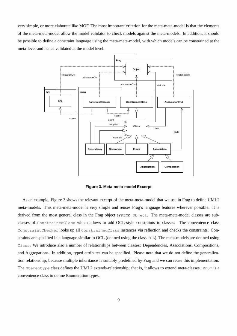
very simple, or more elaborate like MOF. The most important criterion for the meta-meta-model is that the elements
of the meta-meta-model allow the model validator to check models against the meta-models. In addition, it should
be possible to define a constraint language using the meta-meta-model, with which models can be constrained at the
meta-level and hence validated at the model level.
MMM
Frag
Object
ConstrainedClassConstraintChecker
Class
attribute
AssociationEnd
Association
ends
CompositionAggregation
EnumStereotype
FCL
FCL
Dependency
class
extends
supplier
client
«instanceOf»«instanceOf»
«instanceOf»
«instanceOf»
«use»«use»
Figure 3. Meta-meta-model Excerpt
As an example, Figure 3 shows the relevant excerpt of the meta-meta-model that we use in Frag to define UML2
meta-models. This meta-meta-model is very simple and reuses Frag’s language features wherever possible. It is
derived from the most general class in the Frag object system: Object. The meta-meta-model classes are sub-
classes ofConstrainedClass which allows to add OCL-style constraints to classes. The convenience class
ConstraintChecker looks up allConstrainedClass instances via reflection and checks the constraints. Con-
straints are specified in a language similar to OCL (defined using the classFCL). The meta-models are defined using
Class. We introduce also a number of relationships between classes: Dependencies, Associations, Compositions,
and Aggregations. In addition, typed attributes can be specified. Please note that we do not define the generaliza-
tion relationship, because multiple inheritance is suitably predefined by Frag and we can reuse this implementation.
TheStereotype class defines the UML2 extends-relationship; that is, it allows to extend meta-classes.Enum is a
convenience class to define Enumeration types.
9
3.3 Model Integration Concepts: Proven Practices Based Integration
Besides the common meta-meta-model concept, we use proven practices descriptions as the second central model
integration concept: As explained above, we use software patterns to describe proven practices of process-driven
SOAs. Patterns have two characteristics which make them useful for model integration across modeling domains:
• Patterns describe recurring solutions in a particular problem domain in an informal and holistic manner. Hence,
in contrast to most formal modeling notations, they do not abstract from details that go beyond a specific
modeling domain’s abstractions, but instead explain the full solution. That is, if the solution has, for instance,
implications for the workflow, the organization, and the software architecture, all these solution elements are
described.
• As proven practice descriptions, patterns encode the recurring themes in the same kinds of models. Hence, they
are also a good basis for defining a common meta-model for a modeling domain, because patterns typically
describe the established, stable abstractions that are used across different modeling approaches and execution
languages.
Because patterns are defined only informally, we use patternprimitives as an intermediary abstraction to represent
the primitive concerns in the patterns formally. At this point, it is very important that we use a common meta-meta-
model and a common constraint language to define the meta-models that represent the abstract syntaxes of the DSLs:
This way, the primitives can be connected via constraints, and also primitives that cut across different models can
be defined. The model validator can check all structural properties and constraints in the complete model, even if
modeling domains are crossed.
4 Meta-models for Process-Driven Integration of Services
There are many modeling domains that play a role for a process-driven SOA. In our tool chain we have so far
concentrated on a sub-set of these domains that deals with the integration of processes and services. In this domain,
the following types of languages/models are typically used:
• the component architectures,
• the message flow specifications,
• the workflow or business process languages,
• programming languages and snippets written in programminglanguages,
• and business object design models.
10
For our tool chain, we model both, message flow specificationsand workflow or business process languages, using
extension of UML2 activity diagrams1. Component architectures are modeled using UML2 componentdiagrams.
Business object design models are modeled using UML2 class diagrams. In this paper, we will concentrate on
examples that illustrate the integration of component architectures and flow abstractions, but the integration with
business object design models can be done analogously. Programming language snippets are introduced as individual
code (as explained in Section 3.1, cf. Figure 2).
As an example for a meta-model definition let us consider the central flow abstractions: The different models
that are relevant for a process-driven SOA come together in various kinds of “flow” models. There are flow models
for long-running business processes, activity steps in long-running processes, short-running technical processes,and
activity steps in short-running technical processes. Eventhough these flow models have highly different semantic
properties, they share the same basic flow abstraction concept, and at the same time they are a kind of glue for all the
other models that are involved in a process-driven SOA (suchas architecture and design models).
Activitynodeactivity
0..1*
ActivityEdge
edge
activity0..1
*
target
incoming
*
1
ActivityNode
source
outgoing
*
1
ObjectNode ControlNode
FinalNode
ActivityFinalNode FlowFinalNode
JoinNodeForkNode MergeNode DecisionNode InitialNode
Figure 4. UML2 Activity Diagram Meta-model Excerpt
Figure 4 shows the excerpt of the UML2 activity diagram meta-model that is relevant for the following examples
in this paper. We can define this meta-model by instantiatingthe meta-meta-model classes from Figure 3. In the Frag
syntax, the same meta-model looks as follows:
MMM::Class create Activity
MMM::Class create ActivityNode
1Please note that in both cases, long running business processes and short running technical processes, the UML2 activity diagrams must
be extended to depict relevant additional information. Forinstance, to represent long running business processes properly we must also depict
organizational roles, organizational structures, business resources, etc. To represent short running technical processes properly, we must add
technical details, such as protocol information, technical resources, or message queue details. In the examples of this paper, we omit these
details because we want to concentrate on the process/service interaction aspects.
11
MMM::Composition create ActivityNodes -ends {
{Activity -roleName activity -multiplicity 0..1 -navigable 1 -aggregatingEnd 1}
{ActivityNode -roleName node -multiplicity * -navigable 1}
}
MMM::Class create ActivityEdge
MMM::Composition create ActivityEdges -ends {
{Activity -roleName activity -multiplicity 0..1 -navigable 1 -aggregatingEnd 1}
{ActivityEdge -roleName edge -multiplicity * -navigable 1}
}
MMM::Association create ActivityEdgeIncoming -ends {
{ActivityEdge -roleName incoming -multiplicity * -navigable 1}
{ActivityNode -roleName target -multiplicity 1 -navigable 1}
}
MMM::Association create ActivityEdgeOutgoing -ends {
{ActivityEdge -roleName outgoing -multiplicity * -navigable 1}
{ActivityNode -roleName source -multiplicity 1 -navigable 1}
}
MMM::Class create ControlNode -superclasses ActivityNode
MMM::Class create ObjectNode -superclasses ActivityNode
MMM::Class create FinalNode -superclasses ControlNode
MMM::Class create ActivityFinalNode -superclasses FinalNode
MMM::Class create FlowFinalNode -superclasses FinalNode
MMM::Class create ForkNode -superclasses ControlNode
MMM::Class create JoinNode -superclasses ControlNode
MMM::Class create MergeNode -superclasses ControlNode
MMM::Class create DecisionNode -superclasses ControlNode
MMM::Class create InitialNode -superclasses ControlNode
As the meta-models for class and component diagrams are defined pretty much in the same way, we omit them
here.
5 Patterns and Pattern Primitives for Process-Driven Integration of Services
To realize our approach, we must next discuss how to extend the meta-models with pattern primitive extensions.
Before we can go into detail, we first give an overview of the pattern language from which we derive the pattern
primitives.
5.1 Overview: Patterns for process-oriented integration of services
In this section, we give an overview of the pattern language for process-oriented integration of services (for details
please refer to [14]). In the next section, we present the primitives that we have mined from this pattern language. The
pattern language basically addresses conceptual issues inthe Service Composition Layer of a SOA, when following
a process-driven approach to services composition.
12
PROCESS-BASED INTEGRATION ARCHITECTURE
CONFIGURABLE ADAPTERREPOSITORY
PROCES INTEGRATION
ADAPTER
manages
MACROFLOW INTEGRATION
SERVICE
RULE-BASED DISPATCHER
is realized with
forwards requests
delegates requests
offers
is composed of
MICROFLOW ENGINEBUSINESS-DRIVEN SERVICE
CONFIGURABLE ADAPTER
is realized with
manages
MACRO-MICROFLOW
conceptual foundation
is specialization of
MACROFLOW ENGINE
sends requests foractivity execution
interdependent design
is realized with
MICROFLOW EXECUTION
SERVICE
same service interface
Figure 5. Overview: Pattern language for process-oriented integration of services
The patterns and pattern relationships for designing a Service Composition Layer are shown in Figure 5. In
the pattern language, the patternMACRO-MICROFLOW sets the scene and lays out the conceptual basis to the overall
architecture. The pattern divides the flow models into so-called macroflows, which describe the long-running business
processes, andmicroflows, which describe the short-running technical processes.
The PROCESS-BASED INTEGRATION ARCHITECTUREpattern describes how to design an architecture based on
sub-layers for the Service Composition Layer, which is following theMACRO-MICROFLOW conceptual pattern.
The remaining patterns in the pattern language provide detailed guidelines for the design of aPROCESS-BASED
INTEGRATION ARCHITECTURE. In Figure 5 they are thus displayed within the boundaries ofthe PROCESS-BASED
INTEGRATION ARCHITECTUREpattern.
The automatic functions required by macroflow activities from external systems are designed and exposed as ded-
icatedMACROFLOW INTEGRATION SERVICES. PROCESS INTEGRATION ADAPTERSconnect the specific interface
and technology of the process engine to an integrated system. A RULE-BASED DISPATCHERpicks up the (macroflow)
activity execution requests and dynamically decides basedon (business) rules, where and when a (macroflow) activ-
ity is executed. ACONFIGURABLE ADAPTERconnects to another system in a way that allows to easily maintain the
connections, considering that interfaces may change over time. A CONFIGURABLE ADAPTER REPOSITORYmanages
CONFIGURABLE ADAPTERSas components, such that they can be modified at runtime without affecting the systems
sending requests to the adapters. AMICROFLOW EXECUTION SERVICEabstracts the technology specific API of the
13
MICROFLOW ENGINE and encapsulates the functionality of the microflow as a service. A MACROFLOW ENGINE
allows for configuring business processes by flexibly orchestrating execution of macroflow activities and the related
business functions. AMICROFLOW ENGINEallows for configuring microflows by flexibly orchestrating execution of
microflow activities and the relatedBUSINESS-DRIVEN SERVICES. To defineBUSINESS-DRIVEN SERVICES, high-
level business goals are mapped to to-be macroflow business process models that fulfill these goals and more fine
grained business goals are mapped to activities within these processes.
Figure 6 shows an exemplary configuration of aPROCESS-BASED INTEGRATION ARCHITECTURE, in which mul-
tiple macroflow engines execute the macroflows. Process-integration adapters are used to integrate the macroflows
with technical aspects. A dispatching layer enables scalability by dispatching onto a number of microflow engines.
Business application adapters connect to backends.
Process Integration Architecture
Process Integration Adapter Repository
Activity Dispatcher
Microflow Execution Business Application Adapter Repository
Process Integration Adapter A
Process Integration Adapter B
Process Integration Adapter C
Microflow Engine ABusiness
Application Adapter A
Business Application Adapter B
Business Application A
Business Application B
Macroflow Engine A
Macroflow Engine B
Macroflow Engine C
Microflow Engine B
Ser
vice
1
Ser
vice
2
Ser
vice
3
Ser
vice
4
Ser
vice
1
Ser
vice
2
Ser
vice
3
Ser
vice
4
Ser
vice
1
Ser
vice
2
Ser
vice
3
Ser
vice
1
Ser
vice
2
Ser
vice
3
Macroflow integration layer
Activity dispatching
layerMicroflow execution layer Business application services layer
Figure 6. Example Configuration of a Process-based Integrat ion Architecture
5.2 Pattern primitives for Process/Service Integration
In this section, we present the pattern primitives for flow abstractions that we have mined from the pattern language
in Figure 5. We will concentrate only on one example primitive; the other flow abstraction primitives are summarized
in Table 1.
Each primitive is formally defined in the context of the UML2 meta-model using OCL constraints. To illustrate
the formal definition of the primitives let us consider the Macro-Microflow Refinement Primitive. This primitive
models the situation that Microflow Models are allowed to refine Macroflow Models. In addition to macroflows and
microflows, we must consider the Macroflow Steps and MicroflowSteps models, introduced by the Process Flow
Steps primitive: A process activity node in a macroflow or microflow can optionally be refined by a number of
sequential steps that detail the steps performed to realizethe process activity.
14
Primitive Name Description Modeling Solution
Process Flow
Refinement
A macroflow or microflow is refined us-
ing another process flow.
The Activity metaclass is extended with the stereotype ProcessFlowRefinement,
which also introduces tagged values for identifying the refinement.
Process Flow
Steps
A macroflow or microflow is refined by
a number of sequential steps.
A specialization of the ProcessFlowRefinement stereotype,called ProcessFlow-
Steps, is introduced and constrained to be a strictly sequential flow.
Macroflow
Model
A macroflow can be refined by other
macroflows or macroflow steps.
Macroflows are modeled by a ProcessFlowRefinement stereotype, called
Macroflow, and macroflow steps are modeled as a specialization of ProcessFlow-
Steps, called MacroflowSteps.
Microflow
Model
A microflow can be refined by other mi-
croflows or microflow steps.
The microflow model is modeled analogous to the Macroflow Model primitive:
The Microflow and MicroflowSteps stereotypes are introduced.
Macro-Micro-
flow Refinement
Microflow Models are allowed to refine
Macroflow Models.
The Microflow Model primitive is extended: If refinedActivityNode of a Mi-
croflow is not empty, the Microflow is a refinement of a Microflow, a Macroflow,
or MacroflowSteps.
Restricted Ma-
croflow Step
Types
Macroflow Steps are restricted to 3
kinds: process function invocation, pro-
cess control data access, and process re-
source access.
Respective stereotypes for the ActivityNode metaclass areintroduced: InvokePro-
cessFunction, AccessControlDataItem, and AccessProcessResource. The stereo-
types introduce tagged values for identifying the data itemor resource that is ac-
cessed.
Restricted Mi-
croflow Step
Types
Microflow Steps are restricted to 2
kinds: process functions invocations
and process control data access.
This primitive can be modeled using 2 stereotypes for the ActivityNode metaclass:
InvokeProcessFunction and AccessControlDataItem.
Synchronous
Service Invoca-
tion
A service is invoked synchronously. The SyncServiceInvocation, GetInvocationData, and WriteServiceResult stereo-
types extend the Activity Node metaclass.
Asynchronous
Service Invoca-
tion
A service is invoked asynchronously. The AsyncServiceInvocation and GetInvocationData stereotypes extend the Activ-
ity Node metaclass. An asynchronous service invocation might have no result.
Fire and Forget
Invocation
A service is invoked asynchronously
with fire and forget semantics.
The stereotype FireAndForgetInvocation specializes the AsyncServiceInvocation
stereotype. No result is written for this service.
One Reply
Asynchronous
Invocation
A service is invoked asynchronously,
and exactly one result is coming back.
The OneReplyInvocation stereotype specializes AsyncServiceInvocation. We can-
not guarantee that the result comes back in the same Activity, but there must be
exactly one result for a OneReplyInvocation.
Multiple Reply
Asynchronous
Invocation
A service is invoked asynchronously,
and multiple results are coming back.
The MultipleReplyInvocation stereotype specializes AsyncServiceInvocation. We
cannot guarantee that the result comes back in the same Activity, but there must be
at least one result reception.
Process Control
Data Driven In-
vocation
A service is invoked using only data
from the process control data.
A service invocation is modeled by a refined Activity Node stereotyped as Process-
ControlDataDrivenInvocation. This activity must containa ServiceInvocation, and
ReadServiceData/WriteServiceResult must be used which specialize AccessPro-
cessControlData.
Table 1. Flow Abstraction Pattern Primitives Overview
15
«stereotype»MacroflowSteps
«stereotype»MicroflowSteps
«metaclass»Activity
+ refinedActivity : Activity+ refinedActivityNode : ActivityNode
«stereotype»ProcessFlowRefinement
«stereotype»ProcessFlowSteps
«stereotype»Macroflow
«stereotype»Microflow
Figure 7. Macro-/Microflow: Stereotypes for the Primitives
To model this primitive, we first must introduce UML2 stereotypes to distinguish the different kinds of re-
fined/refinement activities (see Figure 7) in the UML2 models. The same extension for the Activity meta-class
looks as follows in the Frag textual syntax:
MMM::Stereotype create ProcessFlowRefinement -extends UML2::Activity \
-attributes {
refinedActivity UML2::Activity
refinedActivityNode UML2::ActivityNode
}
MMM::Stereotype create Microflow -superclasses ProcessFlowRefinement
MMM::Stereotype create Macroflow -superclasses ProcessFlowRefinement
MMM::Stereotype create ProcessFlowSteps -superclasses ProcessFlowRefinement
MMM::Stereotype create MicroflowSteps -superclasses ProcessFlowSteps
MMM::Stereotype create MacroflowSteps -superclasses ProcessFlowSteps
We can model the Macro-Microflow Refinement primitive by constraining the Microflow Activities. In particular,
if the refinedActivityNode and refinedActivity tag values ofa Microflow are not empty, the Microflow is a refinement
of another Microflow, a Macroflow, or a MacroflowSteps Activity. This can be formally modeled using the following
OCL constraint:
-- If a Microflow Activity refines another Activity, then this other Activity
-- must be itself stereotyped as Macroflow, MacroflowSteps, or Microflow.
context Microflow inv:
if (self.refinedActivity->notEmpty() and
self.refinedActivityNode->notEmpty()) then
Macroflow.baseActivity->exist(a | a = self.refinedActivity) or
MacroflowSteps.baseActivity->exist(a |a = self.refinedActivity) or
Microflow.baseActivity->exist(a | a = self.refinedActivity)
endif
The syntax of the FCL constraints, expressed in Frag, have a slightly different syntax than OCL, but are seman-
tically equivalent (i.e. the constraints can be automatically translated between OCL and FCL). Here is the same
16
invariant in the FCL syntax:
Microflow addInvariant {
[FCL if {[FCL notEmpty [self refinedActivity]] &&
[FCL notEmpty [self refinedActivityNode]]} {
[FCL exists a Macroflow {[$a baseActivity] == [self refinedActivity]}] ||
[FCL exists a MacroflowSteps {[$a baseActivity] == [self refinedActivity]}] ||
[FCL exists a Microflow {[$a baseActivity] == [self refinedActivity]}]
}]
}
The task of such constraints is basically to limit the use of the primitives to the acceptable parameters – following
the pattern descriptions in which the primitives are used – but no further. For each primitive we have hence described
all such formal constraints (the others are omitted here forspace reasons). Thus each primitive describes a formal,
parameterizable building block that can be used in the solution of the patterns.
5.3 Modeling patterns using the pattern primitives for process-oriented integration of services
The formal, parameterizable building blocks represented by the pattern primitives are not yet linked to the patterns.
The patterns cannot be themselves formally modeled, but we can identify the pattern primitives that occur in individ-
ual patterns. For instance, some of the primitives are mandatory in a pattern, others are optional, still others are only
used in specific variants, etc. This mapping of patterns to pattern primitives hence provides us with modeling con-
structs that can be differently combined for different pattern instances, but must conform to the pattern-to-primitive
mapping. If a primitive is used in a pattern instance, all formal constraints of the primitive must be fulfilled. Hence,
the primitives formally encode the proven practices documented in the patterns as modeling constructs.
In the remainder of this section, we illustrate our approachusing the example of modeling theMACRO-
MICROFLOW pattern. The other patterns are modeled following the same basic approach. Especially we want
to model that the pattern structures a process model into twokinds of processes, macroflow and microflow. The
pattern strictly separates the macroflow from the microflow,and uses the microflow only for refinements of the
macroflow activities.
Both in macroflows and microflows we can observe refinements. The different kinds of refinement can be modeled
using the Process Flow Refinement primitive. Process Flow Refinement is a generic primitive that can be used for
modeling all kinds of process refinements.
The following code illustrates how the Frag textual DSL syntax can be used to describe a model (we only show
the excerpt forModel1 from Figure 8):
UML2::Activity create Model1
UML2::InitialNode create Model1::Initial
UML2::ActivityNode create Model1::A
UML2::DecisionNode create Model1::Decision1
UML2::ActivityNode create Model1::B
17
«Macroflow»Model1
A
[true]
[false ]
C
«MacroflowSteps»Model2B{refinedActivity=Model1. refinedActivityNode=B}
Y
OB
X
«Microflow»Model3X{refinedActivity=Model2B. refinedActivityNode=X}
[false ]
[true]
K
M
L
«MicroflowSteps»Model4L{refinedActivity=Model3X. refinedActivityNode=L}
F
E
Figure 8. Macro-Microflow modeling example 1
UML2::ActivityNode create Model1::C
UML2::ActivityFinalNode create Model1::Final1
UML2::ActivityFinalNode create Model1::Final2
UML2::ActivityEdge create Model1::Initial1 -source Model1::Initial -target Model1::A
UML2::ActivityEdge create Model1::A1 -source Model1::A -target Model1::Decision1
UML2::ActivityEdge create Model1::Decision1B -source Model1::ABCDecision -target Model1::B
UML2::ActivityEdge create Model1::Decision1C -source Model1::ABCDecision -target Model1::C
UML2::ActivityEdge create Model1::C1 -source Model1::C -target Model1::Final1
UML2::ActivityEdge create Model1::B1 -source Model1::B -target Model1::Final2
## add all model elements to Model1
foreach child [Model1 info children] {
$child activity Model1
}
We describe all models in Figure 8 essentially in the same way. The model integration of the short-running
message flow models and the long-running business models is done by extending the models with the respective
stereotypes and tag values. In the textual syntax this looksas follows:
SOAPrimitives::Macroflow create MacroflowModel1 -baseActivity Model1
SOAPrimitives::MacroflowSteps create MacroflowStepsModel2B \
-baseActivity Model2B -refinedActivity Model1 \
-refinedActivityNode Model1::B
SOAPrimitives::Microflow create Microflow3X \
-baseActivity Model3X -refinedActivity Model2B \
-refinedActivityNode Model2B::X
SOAPrimitives::MicroflowSteps create Microflow4L \
-baseActivity Model4L -refinedActivity Model3X \
-refinedActivityNode Model3X::L
After these stereotypes have been defined, the OCL constraints of the primitives enforce that those four models can
only be composed in a way that is valid according to the Macro-Microflow Refinement primitive. Figure 8 hence
18
shows a model conforming to the constraints.
For theMACRO-MICROFLOW pattern it is mandatory that the Macro-Microflow Refinement primitive is used, and
at least one Macroflow Model and one Microflow Model with a refinement relationship between them must be present
in a model. There are different specific kinds of refinement possible:
• Macroflows can be refined by other macroflows. That is, a Macroflow Model refines another Macroflow Model.
• Microflows can be refined by other microflows. That is, a Microflow Model refines another Microflow Model.
• Macroflows can be refined by microflows. That is, a Microflow Model refines another Macroflow Model.
• Often it is additionally possible to refine each activity in amacroflow or microflow using a sequence of activity
steps. This can also be modeled using the Process Flow Steps primitive, either at the Macroflow Model or
Microflow Model level.
The Macro-Microflow Refinement primitives allows us to modela number of pattern variants of theMACRO-
MICROFLOW pattern. For instance, theMACRO-MICROFLOW structure may strictly follow a refinement in macroflow
→ macroflow steps→ microflow → microflow steps. Figure 8 shows an example of such a refinementusing the
UML2 representations of the pattern primitives.
Another, different exemplary structure is that the macroflows at the highest level depict the main business pro-
cesses, which are then refined by other macroflows depicting sub-processes that are still business-oriented. These
macroflows are refined stepwise via other macroflows. Finally, the macroflow activities of the lowest granularity are
refined by microflows. That is, in this second example, there are no process flow steps used in the model, but multiple
refinements at the macroflow level. Figure 9 shows an example of such a refinement using the UML2 representations
of the pattern primitives.
«Macroflow»MainBusinessProcess1
A
[true]
[false ]
C
«Macroflow»SubprocessB{refinedActivity= MainBusinessProcess 1, refinedActivityNode=B}
Y
B
X
«Macroflow»BusinessProcessActivityZ{refinedActivity= SubProcessB, refinedActivityNode=Z}
[false ]
[true]
K
L
«Microflow»ActivityL{refinedActivity= BusinessProcessActivity , refinedActivityNode=L}
E
Z
F
Figure 9. Macro-Microflow modeling example 2
Numerous other variants of theMACRO-MICROFLOW pattern are possible and can hence be modeled with the
primitives introduced in the previous section. Please notethat the flexibility of model assembly through primitives is
19
a very important characteristic of our approach, because itenables us to represent the inherent variability of software
pattern solutions.
6 Modeling Architectural Abstractions in Process-Driven Integration Of Services
As seen above, theMACRO-MICROFLOW pattern has implications for short-running message flow models and the
long-running business models, and we were able to integratethe two model types (and even add macroflow/microflow
steps as an another kind of modeling abstraction). In our approach, these two kinds of models are modeled with the
same model type: activity diagrams. The patterns, however,also have implications for other model types, such as
the architectural components in the system or business object models. To model those abstractions, we additionally
need to consider architectural abstractions and object-oriented design abstractions.
In UML, business objects can be modeled using class diagrams. Architectural abstractions can be modeled via
component diagrams. Component diagrams are a specialization of class diagrams. Therefore, our approach for
integrating those models with flow models is very similar forboth class diagrams and component diagrams. Hence,
we demonstrate our approach only for one of those abstractions in depth: architectural components.
Our approach is to first find suitable pattern primitives for modeling the architectural abstraction. If further inte-
gration is needed, we try to model the flow model and architectural model in parallel, especially with overlapping
constraints. If such a “loose” integration is not enough, wemodel primitives and constraints that cut across model
boundaries. In the following sub-sections, we will demonstrate each of these solutions in turn.
6.1 Modeling Architectural Abstractions with Pattern Prim itives
Architectural modeling with pattern primitives follows the same approach as introduced for the flow abstractions.
In the context of architectural abstraction, we have introduced similar primitives for architectural patterns (see [34]).
Let us consider thePROCESS-BASED INTEGRATION ARCHITECTUREpattern and the Callback primitive as an ex-
ample.
In the PROCESS-BASED INTEGRATION ARCHITECTUREpattern, different kinds of components are connected.
Figure 6 shows an exemplary larger configuration, in which multiple macro-/microflow engines and a dispatcher are
used. Of course, there are also significantly smallerPROCESS-BASED INTEGRATION ARCHITECTUREconfigura-
tions. For instance, a single macroflow engine can interact directly with a single microflow engine, which connects
to backends via service-based adapters. The modeling support for the PROCESS-BASED INTEGRATION ARCHI-
TECTURE pattern should allow for flexibly assembling different kinds of PROCESS-BASED INTEGRATION ARCHI-
TECTURE models. In thePROCESS-BASED INTEGRATION ARCHITECTUREthis flexibility is achieved by following
asynchronous messaging patterns from [15].
The Callback primitive [34] can be used to model the reactivebehavior in these patterns: A callback denotes an
invocation to a componentB that is stored as an invocation reference in a componentA. The callback invocation is
20
executed later, upon a specified set of runtime events. Between two componentsA andB, a set of callbacks can be
defined. To capture the semantics of callbacks properly in UML, we propose five stereotypes:
• IEvent: A stereotype that extends the ‘Interface’ metaclass and contains a number of methods that are exclu-
sively trigger events for a callback.
• ICallback: A stereotype that extends the ‘Interface’ metaclass and contains a number of methods that serve
exclusively as callback methods.
• EventPort: A stereotype that extends the ‘Port’ metaclass and is typedby two interfaces: IEvent as aprovided
interface and ICallback as arequiredinterface.
• CallbackPort: A stereotype that extends the ‘Port’ metaclass and is typedby two interfaces: ICallback as a
providedinterface and IEvent as arequiredinterface.
• Callback: A stereotype that extends the ‘Connector’ metaclass and specifies the semantics of a callback
connector, which connects an EventPort of a component to a matching CallbackPort of another component.
Again, we have formalized the constraints using OCL (see [34]), and defined the meta-model and constraints in
Frag, so that we can use the constraints on components that represent thePROCESS-BASED INTEGRATION ARCHI-
TECTURE components.
All components in aPROCESS-BASED INTEGRATION ARCHITECTUREare interconnected following the callback
style because they use asynchronous communication. The event ports of each layer are listening to events from
the higher-level layer, and when an event arrives, they callinto the lower-level layer. Once a result is received, it
is propagated back into the higher-level layer using a Callback. Figure 10 shows an example UML2 model for a
Callback configuration modeling the situation from Figure 6in a more formal way.
:Macroflow Engine
:PI_Adapter
:Dispatcher
:MicroflowEngine
:MicroflowEngine
:BA_Adapter
:BA_Adapter
:BA_Adapter
«Callback»
«CallbackPort»
«EventPort»
:Macroflow Engine :PI_Adapter
«Callback»
«CallbackPort»
«EventPort»
:Macroflow Engine
:PI_Adapter
«Callback»
«CallbackPort»
«EventPort»
«CallbackPort»
«CallbackPort»
«EventPort»
«CallbackPort»
«Callback»
«CallbackPort»
«Callback»
«EventPort»
«EventPort»
«EventPort»
«EventPort»
«EventPort»
«CallbackPort»
«CallbackPort»
«Callback»
«Callback»
«Callback»
«Callback»
Figure 10. UML2 Model for the Example Configuration
21
6.2 Integrating Architectural and Flow Abstraction Models by Modeling in Parallel
In addition to the architectural flexibility of thePROCESS-BASED INTEGRATION ARCHITECTUREpattern, we need
to model the pattern’s constraints. If the pattern implementation follows theMACRO-MICROFLOW pattern, analogous
constraints to the macro-microflow refinement in the flow models must be introduced, such as: components that
represent the microflow should not invoke macroflow functionality, macroflow adapters should not be used at the
microflow level and vice versa, the dispatcher should only invoke short running microflows, etc. Such issues can be
modeled “in parallel” to the flow model. That is, we do not needprimitives or constraints that cut across modeling
domains.
In this situation, we can use another architectural primitive from [34]: Layering. Layering describes groups of
components and further constrains them. Specifically, it entails that group members from layerX may call into layer
X − 1 and components outside the layers, but not into layerX − 2 and below. To model Layering in UML2, we
introduce theLayer stereotype, which specializes theGroup stereotype (which itself is an extension of the Package
metaclass). We also impose the following constraints: a component can only be member of one layer and not multiple
layers; components who are members of layerX may call their fellow components in layerX, as well as components
in layer X − 1 but not in other layers (e.g.X − 2 and below). It is noted that there is no constraint about calling
components in layerX + 1 or above, since this is a specific issue to the pattern realization. Also, we introduce the
tag definition layerNumber for Layers which represents the number of the layer in the ordered structure of layers.
Figure 11 shows an UML2 model that extends the model from Figure 10 using the Layering primitive.
«Layer»Business
application services
{layerNumber=1}
BA_Adapter
«Layer»Microflow execution
{layerNumber=2}
MicroflowEngine
«Layer»Activity
dispatching layer
{layerNumber=3}
Dispatcher
«Layer»Macroflow
integration layer{layerNumber=4}
PI_Adapter
«Layer»Macroflow
Engine{layerNumber=5}
Macroflow Engine
Figure 11. Extending the Example Configuration with Layerin g
In this example, we have modeled the integration of the macroflow-microflow refinements at the flow model level
with the architectural components by introducing OCL constraints for the refinements between the flow models, and
by adding similar constraints to the architectural model. That is, the primitive Macro-Microflow Refinement was used
at the flow model level and Callback/Layering were used at thearchitectural level. Sometimes this is not enough,
and it is necessary to extend this strategy and add a direct relationship between the flow models and the architectural
models. Then the solution described in the next section should be used.
22
6.3 Integrating Architectural and Flow Abstraction Models Using Cross-Model Primitives
In some cases it is necessary to introduce a formal dependency between different model types to model a concern
properly. For instance, to correlate the events and callbacks between the components, we usually pass aCORRELA-
TION IDENTIFIER [15] between the components. In the component model, we needto model which components use
which CORRELATION IDENTIFIER because in aPROCESS-BASED INTEGRATION ARCHITECTUREmultiple CORRE-
LATION IDENTIFIERS can be used. In addition, we must ensure that the macroflow andmicroflow models pass a
valid CORRELATION IDENTIFIER type to all asynchronous invocations.
To model this situation, we first introduce a new architectural primitive, Correlation. Like Layering, the Correla-
tion primitive also extends the Grouping primitive from [34]. It introduces two stereotypes:
• CorrelationIdentifier: A stereotype that extends the ‘Class’ metaclass and contains a tag value
correlationGroup of the typePackage.
• CorrelationGroup: A subclass of theGroup stereotype which extends the ‘Package’ metaclass.
There are the following constraints: A correlation group package, used in the tag valuecorrelationGroup, must
be stereotyped asCorrelationGroup. Each correlation group must have aCorrelationIdentifier with a
correlationGroup tag value that points to it.
Using this primitive we can define that certain components belong to a correlation group and use a specific class (or
component) as correlation identifier. For instance, the component model in Figure 12 expresses that the components
MacroflowEngine, PIAdapter, and Dispatcher form a correlation group with the correlation identifier CID.
«MacroflowSteps»MFSteps{refinedActivity=.... refinedActivityNode=...}
C_ID«ReadServiceData»
ReadData
DispatcherPI_Adapter«MacroflowEngine»Macroflow Engine
{activities = MFSteps, ...}
«CorrelationIdentifier»C_ID
{correlationGroup = MacroflowCorrelationGroup}
«CorrelationGroup»MacroflowCorrelationGroup
«AsyncServiceInvocation»Invoke
Figure 12. Correlation Identifier Group
To model the dependency to the macroflow/microflow models we introduce two new primitives for modeling the
patternsMACROFLOW ENGINE and MICROFLOW ENGINE, which are part of thePROCESS-BASED INTEGRATION
ARCHITECTURE. The goal is to be able to model which macroflow models are executed on whichMACROFLOW
23
ENGINE and which microflow models are executed on whichMICROFLOW ENGINE. We introduce three new stereo-
types:
• ProcessEngine: A stereotype that extends the ‘Component’ metaclass and contains a tag valueactivities
of the typeActivity.
• MacroflowEngine: A stereotype that subclassesProcessEngine to specify a component that executes
macroflows.
• MicroflowEngine: A stereotype that subclassesProcessEngine to specify a component that executes
microflows.
There is are OCL constraints that specify that aMacroflowEngine can only haveactivities that are stereotyped
either as Macroflow or MacroflowSteps. AMicroflowEngine can only haveactivities that are stereotyped
either as Microflow or MicroflowSteps. That is, using these primitives and the constraints, we have introduced a
formal dependency between the component and flow models.
Finally, we need to specify the correlation constraints as an OCL constraint:
-- If this process engine is part of a correlation group, then
-- all AsyncServiceInvocation activity nodes of activities
-- that belong to this engine must have an incoming Object Node that is
-- of the CorrelationIdentifier type of the engine’s correlation group:
context ProcessEngine inv:
if (CorrelationGroup->exists(cg |
cg.basePackage.importedMember->exists(cgm |
self.baseComponent = cgm))) then
self.activities->forAll(a |
if (AsyncServiceInvocation->exists(ais |
ais.baseActivityNode = an)) then
an.incoming->exists(in |
CorrelationIdentifier->exists(cid |
in.source.oclIsKindOf(ObjectNode) and
in.source.type->size() = 1 and
in.source.type = cid.baseClass))
endif)
endif
Now we have ensured that all asynchronous invocations in a correlation group’s activities – at the macroflow,
macroflow steps, microflow, and microflow steps level – must have a correlation identifier type of the correlation
group as an incoming object node in the activity diagram. An example activity for the macroflow correlation group
example is also shown in Figure 12.
24
7 Related Work
A number of other approaches for the documentation of SOA proven practices are available. For instance, a
number of reference architectures and blueprints have beenproposed [27, 5, 28]. These approaches focus on specific
technologies and apart from this specific focus neither modeling support nor tool support that is more universally
applicable has been proposed.
Zimmermann et al. present a generic modeling approach for SOA projects [36]. As in our approach, the approach
by Zimmermann et al. is based on project experiences and distills proven practices from practical cases. The approach
also integrates multiple kinds of models for a SOA:
• object-oriented analysis and design,
• enterprise architecture, and
• business processes.
Even though there are many similarities to our approach, there is the difference that the authors use rather informal
models to illustrate their approach and do not provide a concept for explaining the conceptual building blocks of the
architecture (like the patterns in our approach). They do not provide a concept for using the approach in the context
of MDSD.
Some other approaches define particular aspects of service or business process composition using formal specifi-
cations, such as activity-based finite automata [11] or interval temporal logic [24]. Desai et al. [7] propose to abstract
business processes using interaction protocol componentswhich represent an abstract, modular, publishable specifi-
cation of an interaction among different partner roles in a business process. In general, however, these approaches
in the first place aim to support verifiability, and hence can only model specific aspects of service composition. Our
approach aims for a significantly extended scope: general purpose modeling of process-driven SOAs based on a
formalization of proven practices and model-driven tool support.
Some approaches use the Semantic Web to model the integration of (Web) services and process. OWL-S [6]
includes a process model for Web services and it uses semantic annotations to enable dynamic composition. Cardoso
and Sheth [4] use Semantic Web ontologies to facilitate the interoperability of heterogeneous Web services in the
context of workflows. This is a different – though not contradictory – approach to model the integration of services
and processes than the process flow paradigm used in our approach.
There are many modeling approaches for business processes.Two out of many examples are Event-Driven Process
Chains (EPC) [17] and the BPMN [21]. Both approaches are related to our approach because they focus on one (of
the many) modeling aspects of process-driven SOAs, business process modeling. Our approach has in common
with these approaches that we use the flow abstraction as the central modeling abstraction. Unlike the BPMN, our
approach is based on a formal meta-model. Among others, Kindler has proposed formal semantics for EPCs [18].
In contrast to modeling approaches for business processes,our approach allows to integrate other models covering
25
aspects of software design, software architectures, messages flows, etc. of a process-driven SOA. That is, we take a
more “integrative” view than those more specific approaches.
Business process management tools, such as Adonis [1] or Aris [16], describe a holistic model of business process
management, ranging from strategic decisions to the designof business processes. They also provide mappings
(imports/exports) to the realization and execution of processes. They are integrated with standard model types and
extensible with new model types. Such tools are related to our approach at a high level because they represent
important prior art in the field of model integration. But they do not – such as our approach – concentrate on models
based on proven practices. They also do not specifically focus on the field of process-driven SOAs; they are more
focused on the business processes. However, an extensible tool suite like Adonis can be used for providing input
models for our approach or be extended to model the DSLs in ourapproach.
The workflow patterns [2] describe concepts of workflow languages. They are conceptually closer to our notion of
pattern primitives than to the pattern concept as it is used in the pattern community. That is, the workflow patterns are
formalizable constructs (e.g., formalized in the Petri-net-based language YAWL). The general approach to formalize
pattern primitives using (colored) Petri nets is also applicable to our approach, e.g., if validation or verification isthe
goal. We use a formalizable subset of the UML and OCL instead because our goals are a general modeling support,
model validation, and to formally integrate different models of a SOA.
Our approach extends the MDSD concept proposed for instancein [26, 12] with the idea to use one common meta-
meta-model for model integration, pattern primitives as modeling constructs based on proven practices, and model
validation tools for these concepts. In Chapter 13 of the book Software Factories [12] it is briefly discussed how
typical MDSD concepts can be used to support SOA modeling, but only with a focus on Web Services technology.
Essentially, the process description, e.g. in BPEL, is seenas a platform for implementing abstractions in a product
line, and the services are seen as product line assets for systematic reuse. This view does not contradict our approach,
but our approach goes beyond this vision. Through the commonmeta-meta-model we can integrate any kind of model
types; hence, process descriptions are not only a platform,but a first-class model type. In the software factories
approach, it is advised that patterns are used as proven practices, but there is no guidance how to map them to formal
modeling constructs, like the pattern primitives in our approach. Of course, any MDSD approach can be extended to
support our approach.
There are a number of UML profiles for various SOA aspects. Wada et al. [31] propose an UML profile to model
non-functional aspects of SOAs and present an MDSD tool for generating skeleton code from these models. Heckel
et al. [13] propose a UML profile for dynamic service discovery in a SOA by providing stereotypes that specify
the relationships among service implementations, serviceinterfaces, and requirements. Gardner et al. [10] define
a UML profile to specify service orchestration with the goal to map the specification to BPEL code. Vokac and
Glattetre [30] use – as in our examples – UML profiles to define DSLs. The proposed UML profile supports data
integration issues. Even though these approaches focus on different application areas of a SOA, they share similar
characteristics: In contrast to our approach, they focus ona single type of model, not on model integration or on
26
extensibility with other model types. The modeling constructs are not systematically derived from proven practices.
Hence, the approaches are very specific for the application area they focus on. By redefining such profiles to conform
to a common meta-meta-model they could, however, be integrated into our approach.
There are also a number of related approaches for the formalization of pattern specifications [8, 20, 25, 19]. These
approaches mainly describe simple single patterns from [9]in a formal manner. But there are a number of issues
with these approaches: First, these approaches in first place do only specify a specific implementation variant of
these patterns, not all possible variants. That is, they aretoo limited in the abstractions they propose to grasp the
rich concepts found in patterns, and do not do not deal with the inherent variability found in pattern descriptions.
Secondly, they do not provide a concept for dealing with the central concept of pattern languages which explain the
relationships of different pattern-based design decisions in terms of sequences. We have resolved these problems
using the pattern primitive concept and applied our primitives to a pattern language that is (much) more complex
than single patterns from [9] – a central prerequisite for a complex domain like process-driven SOAs.
8 Evaluation
In this paper, we have introduced a particular combination of features to model process-driven SOAs based on
proven practices. In contrast to the related work in this area, we have defined a tool chain for MDSD, which is
extensible with domain-specific modeling languages for different model types. We support models for business
processes, message flows, OO design, and software architecture – and programming language code/snippets provided
as individual code in the MDSD tool chain. Our approach is extensible with new model types, especially domain-
specific models. We plan to extend our approach in additionalrelevant modeling domains, such as organizational
models or human-interaction models. None of the related approaches offers sufficient support for all these model
types. Except for the approach by Zimmermann et al., Adonis/Aris, and MDSD/software factories, the related work
concentrates mostly on one type of modeling domain.
Adonis/Aris provide an explicit extensibility model for model types. MDSD/software factories provide the same
extensibility model as our approach: DSLs based on formal meta-models.
Cross-model integration is partially supported by many of the other approaches. However, usually there are less
modeling domains supported for specific modeling approaches. The integration is often not defined formally (e.g.
through a common meta-meta-models or a constraint language). Some approaches, like BPMN, provide the notion of
different kinds of abstractions, but do not introduce multiple modeling views. MDSD/software factories, of course,
integrate the models in the code generator, but usually not at the meta-model level. In MDSD/software factories it is
generally possible to follow our approach to cross-model integration. A common meta-meta-model is not enforced,
though it is common (i.e., to use the model of the generator asa common meta-meta-model).
Our approach is not the only approach that is based on proven practices, but only our approach and the workflow
patterns approach combine proven practices and formal models. In YAWL, the workflow patterns are provided as
language constructs; hence in the workflow patterns approach the flexibility of assembly of pattern primitives is not
27
Modeling
constructs
based on
proven
practices
Formalized
models
Meta-
model
validation
Constraint
validation
Model-
based
verification
Cross-
model
integration
Extensibi-
lity model
for model
types
Reference architec-
tures & blueprints
[27, 5, 28]
yes no no no no partially no
Approach by Zimmer-
mann et al. [36]
yes no no no no partially no
Formal specification
approaches [11, 24]
no yes no no yes no no
Interaction protocols
[7]
no yes no no yes partially no
Semantic Web Ser-
vices [6, 4]
no yes partially no no partially no
EPC [17, 18] no yes no no yes no no
BPMN [21] no no no no no partially no
Adonis [1], Aris [16] no no partially partially no partially yes
Workflow patterns +
YAWL [2]
yes yes no no yes no no
MDSD/Software Fac-
tories [26, 12]
no yes yes yes no partially yes
UML profiles for SOA
[31, 13, 10, 30]
no partially partially partially no no no
Pattern primitives
based MDSD for
process-driven SOA
yes yes yes yes no yes yes
Table 2. Evaluation of the approach
28
(yet) supported, because the variation points offered by the primitives are not offered by the workflow patterns. To
support a similar approach as ours, it would be necessary to mine higher-level patterns in workflows that provide
guidance on how to assemble the workflow patterns to larger structures.
Semantic Web Services approaches partially support model-based validation because a certain conformance check
against the ontology can be performed. In tools like Adonis/Aris, the model type conformance can be checked
implicitly through the tool. In general, for MDSD/softwarefactories it is possible to check conformance to the meta-
models and constraints. Many MDSD tools support model validation and constraint checking. The UML profiles do
not themselves support model validation or constraint checking, but as they are standardized, existing tools can be
used.
The more formal approaches in the related work often aim for model-based verification. Our approach is not
designed for this goal. Of course, it is possible to define verifiable models through meta-models and extend our
approach, but this has not yet been the focus of our work. The same can be assessed for the MDSD/software
factories approach.
The evaluation of our approach is summarized in Table 2. As can be seen, none of the related work takes such an
integrative view as our approach. Therefore, modeling all aspects of process-driven SOAs was not well supported.
The related work rather concentrates on some specific aspects of process-driven SOA, such as flow abstractions,
modeling business processes, integration of ontologies and services, verification, etc. Hence, these approaches cannot
provide a complete foundation for a model integration approach for process-driven SOA models.
Another distinguishing characteristic of our approach is that it is based on proven practices. In our experience, this
helps especially to find the integration spots between the different models and to find adequate modeling abstractions
in the various modeling domains.
9 Conclusion
In this paper, we have introduced a concept for model-drivendevelopment of process-driven SOAs that is based on
proven practices. We have especially focused on the aspect of model integration by introducing an approach that is
based on a common meta-meta-model from which concrete meta-models for DSLs are derived. In the different DSLs
and their respective meta-models, patterns are formalizedas pattern primitives, so that the pattern’s constraints can be
ensured for all instances of all different meta-models. We have shown in the examples how to integrate message flow
models, business process models, and architectural models. The approach is, however, applicable for all other kinds
of process-driven SOA models for which a formal meta-model can be given. Our tools and DSLs can be flexibly
used in model-driven development for formally specifying process-driven SOAs, validating the models, and code
generation in executable languages.
References
[1] BOC Europe. Adonis. http://www.boc-eu.com/, 2006.
29
[2] W. Aalst, A. Hofstede, B. Kiepuszewski, and A. Barros. Workflow patterns.Distributed and Parallel Databases,
14:5–51, 2003.
[3] C. Alexander.The Timeless Way of Building. Oxford Univ. Press, 1979.
[4] J. Cardoso and A. Sheth. Semantic e-workflow composition. J. Intell. Inf. Syst., 21(3):191–225, 2003.
[5] M. Champion. Towards a reference architecture for Web services. http://www.idealliance.org/papers/dxxml03/
papers/04-01-01/04-01-01.pdf, 2004.
[6] DAML Services. OWL-S 1.1 Release. http://www.daml.org/services/owl-s/1.1/, 2004.
[7] N. Desai, A. U. Mallya, A. K. Chopra, and M. P. Singh. Interaction protocols as design abstractions for business
processes.IEEE Transactions on Software Engineering, 31(12):1015–1027, 2005.
[8] A. H. Eden and Y. Hirshfeld. LePUS – symbolic logic modeling of object oriented architectures: A case study.
In Second Nordic Workshop on Software Architecture - NOSA’99, Ronneby, Sweden, April 1999.
[9] E. Gamma, R. Helm, R. Johnson, and J. Vlissides.Design Patterns: Elements of Reusable Object-Oriented
Software. Addison-Wesley, 1994.
[10] T. Gardner. Uml modeling of automated business processes with a mapping to bpel4ws. InECOOP Workshop
on Object Orientation and Web Services, Darmstadt, Germany, July 2003.
[11] C. E. Gerede, R. Hull, O. Ibarra, and J. Su. Automated composition of e-services: Lookaheads. InProceedings
of the International Conference on Service Oriented Computing (ICSOC 2004), pages 252–262, New York, NY,
US, June 2004.
[12] J. Greenfield and K. Short.Software Factories: Assembling Applications with Patterns, Frameworks, Models
& Tools. J. Wiley and Sons Ltd., 2004.
[13] R. Heckel, M. Lohmann, and S. Thoene. Towards a uml profile for service-oriented architectures. InWorkshop
on Model Driven Architecture: Foundations and Applications (MDAFA) 2003, CTIT Technical Report TR-CTIT-
03-27, University of Twente, Enschede, The Netherlands, June 2003.
[14] C. Hentrich and U. Zdun. Patterns for process-orientedintegration in service-oriented architectures. InPro-
ceedings of 11th European Conference on Pattern Languages of Programs (EuroPlop 2006), Irsee, Germany,
July 2006.
[15] G. Hohpe and B. Woolf.Enterprise Integration Patterns. Addison-Wesley, 2003.
[16] IDS Scheer. Aris Platform. http://www.idsscheer.de/germany/products/53956, 2006.
30
[17] G. Keller, M. Nuettgens, and A.-W. Scheer. Prozessmodellierung auf der grundlage ereignisgesteuerter prozess-
ketten (epk). Technical Report Veroeffentlichungen des Instituts fr Wirtschaftsinformatik (IWi), Heft 89, Uni-
versitaet des Saarlandes, 1992.
[18] E. Kindler. On the semantics of epcs: Resolving the vicious circle.Data & Knowledge Engineering, 56(1):23–
40, 2006. Elsevier.
[19] J. Mak, C. Choy, and D. Lun. Precise modeling of design patterns in UML. In Proceedings of the 26th
International Conference on Software Engineering (ICSE’04), pages 252–261, Edinburgh, Scotland, United
Kingdom, 2004. IEEE Computer Society.
[20] T. Mikkonen. Formalizing design patterns. InProceedings of the 20th International Conference on Software
Engineering, pages 115–124, Kyoto, Japan, 1998. IEEE Computer Society.
[21] Object Management Group. Business Process Modeling Notation (BPMN). http://www.bpmn.org/, 2006.
[22] Open Architecture Ware. openArchitectureWare 4.1. http://www.openarchitectureware.org/, 2006.
[23] D. Schmidt and F. Buschmann. Patterns, frameworks, andmiddleware: Their synergistic relationships. In25th
International Conference on Software Engineering, pages 694–704, May 2003.
[24] M. Solanki, A. Cau, and H. Zedan. Augmenting semantic web service descriptions with compositional speci-
fication. InWWW ’04: Proceedings of the 13th international conference on World Wide Web, pages 544–552,
2004.
[25] N. Soundarajan and J. O. Hallstrom. Responsibilities and rewards: Specifying design patterns. InProceedings
of the 26th International Conference on Software Engineering, pages 666–675. IEEE Computer Society, 2004.
[26] T. Stahl and M. Voelter.Model-Driven Software Development. J. Wiley and Sons Ltd., 2006.
[27] Sun. Sun reference architectures. http://www.sun.com/service/refarch/, 2004.
[28] The Middleware Company. SOA blueprints. http://www.middlewareresearch.com/soa-blueprints/, 2004.
[29] S. Vinoski. Integration with Web services.IEEE Internet Computing, November/December 2003.
[30] M. Vokac and J. M. Glattetre. Using a domain-specific language and custom tools to model a multi-tier service-
oriented application - experiences and challenges. InProc. of Model Driven Engineering Languages and Sys-
tems, 8th International Conference, MoDELS 2005, pages 492–506, Montego Bay, Jamaica, October 2005.
[31] H. Wada, J. Suzuki, and K. Oba. Modeling non-functionalaspects in service oriented architecture. InProc. of
the 2006 IEEE International Conference on Service Computing, Chicago, IL, September 2006.
[32] U. Zdun. Frag. http://frag.sourceforge.net/, 2005.
31
[33] U. Zdun. Tailorable language for behavioral composition and configuration of software components.Computer
Languages, Systems and Structures: An International Journal, 32(1):56–82, 2006.
[34] U. Zdun and P. Avgeriou. Modeling architectural patterns using architectural primitives. InProceedings of
the 20th ACM Conference on Object-Oriented Programming, Systems, Languages & Applications (OOPSLA
2005), pages 133–146, San Diego, CA, USA, October 2005. ACM Press.
[35] U. Zdun, C. Hentrich, and W. van der Aalst. A survey of patterns for service-oriented architectures.Interna-
tional Journal of Internet Protocol Technology, 1(3):132–143, 2006.
[36] O. Zimmermann, P. Krogdahl, and C. Gee. Elements of Service-Oriented Analysis and Design: An interdis-
ciplinary modeling approach for SOA projects. http://www-128.ibm.com/developerworks/webservices/library/
ws-soad1/, Jun 2004.
32