Page 1
Modeling and Design of RobustDigital Controller for Gimbal Control
Actuator of a Launch Vehicle
Preliminary Thesis Report
Submitted in partial fulfillment of the requirements for the award of M.Tech
Degree in Electrical Engineering
(Control Systems)
University of Kerala
Submitted by
Aparna S
M3 CS
No : 12400004
DEPARTMENT OF ELECTRICAL ENGINEERING
COLLEGE OF ENGINEERING TRIVANDRUM
THIRUVANANTHAPURAM-16
Page 3
Department of Electrical Engineering
College of Engineering, Trivandrum
Thiruvananthapuram-16
2014
Certificate
This is to certify that this report entitled “Modeling and Design of Robust DigitalController for Gimbal Control Actuator of a Launch Vehicle ” is a bonafide recordof the preliminary project work done by Aparna S. of 3rd Semester, M.Tech under ourguidance towards the partial fulfillment of the requirements for the award of M.Tech Degreein Electrical & Electronics Engineering (Control Systems) of the University ofKerala during the year 2014.
Dr. Dinesh Pai A. Ms. Revathy H Ms. Preethisree G.Professor Division Head Scientist/Engineer-SDDepartment of Electrical Engineering AEMD/CEAG CED/CEAGCollege of Engineering, Trivandrum LPSC, Valiamala LPSC, ValiamalaInternal Guide External Guide External Guide
Dr. S. Ushakumari Prof. A.S. ShajilalProfessor ProfessorDepartment of Electrical Engineering Department of Electrical EngineeringCollege of Engineering, Trivandrum College of Engineering, Trivandrum(Group Head) (P.G Co-ordinator)
Page 4
Prof. S. LylaHead of the DepartmentDepartment of Electrical EngineeringCollege of Engineering, Trivandrum
2
Page 5
Acknowledgement
I have great pleasure in expressing my gratitude and obligations to Ms. Revathy H.,,
Group Head, CGDG/CGSE,LPSC andMs. Preethisree G.,,Scientist/Engineer,CED/CEAG,LPSC
for their valuable guidance and suggestions to make this work a great success.
I express my thanks to Dr. Dinesh Pai A., Professor, Department of Electrical En-
gineering, College of Engineering, Trivandrum, for all necessary help extended to me in the
fulfillment of this work.
I extend my gratitude to Dr. S. Ushakumari, Group Head, Department of Electrical
Engineering, College of Engineering Trivandrum for being a source of constant support and
encouragement.
I express my sincere thanks to Prof. A. S. Shajilal, Professor & PG Co-ordinator,
Department of Electrical Engineering, College of Engineering Trivandrum.
I express my gratitude to Prof. S. Lyla, Professor & Head of the Department, Depart-
ment of Electrical Engineering, College of Engineering Trivandrum.
I also acknowledge my gratitude to other members of faculty in the Department of Elec-
trical Engineering, my family, friends and seniors for their whole hearted cooperation and
encouragement. Above all, I thank GOD Almighty, without whose help, I wouldn’t have
reached this far.
Trivandrum Girija S.
i
Page 6
Abstract
Compared with analog controllers, digital ones are more stable and easier to adjust
parameter. Digital controllers are usually implemented with FPGA for its fast and stable
performance. The process of converting analog controllers to digital one is studied in depth.
Implementation of digital controllers in embedded environment suffers from the inherent
problems associated with analog-digital signals interfacing in hard real-time, therefore, the
control algorithms are invariantly subjected to approximations. This work presents a tech-
nique for implementation of an efficient FPGA based robust digital controller for the position
control of a permanent magnet DC high torque motor. The implementation technique cir-
cumnavigates the problem of interfacing analog and digital systems in real-time.
Page 7
Contents
1 Introduction ii
2 Literature Review iv
3 System Modeling vii
3.1 System Description . . . . . . . . . . . . . . . . . . . . . . . . . . . . . . . . vii
3.2 Nomenclature . . . . . . . . . . . . . . . . . . . . . . . . . . . . . . . . . . . viii
3.3 System Modeling . . . . . . . . . . . . . . . . . . . . . . . . . . . . . . . . . ix
3.3.1 PMDC Motor . . . . . . . . . . . . . . . . . . . . . . . . . . . . . . . ix
3.3.2 Gear Mechanism . . . . . . . . . . . . . . . . . . . . . . . . . . . . . x
3.3.3 Engine . . . . . . . . . . . . . . . . . . . . . . . . . . . . . . . . . . . x
3.3.4 Feedback Section . . . . . . . . . . . . . . . . . . . . . . . . . . . . . x
3.4 Limitations of the System . . . . . . . . . . . . . . . . . . . . . . . . . . . . xi
4 Simulation Results xii
4.1 Modeled System Simulation . . . . . . . . . . . . . . . . . . . . . . . . . . . xii
4.2 Modeled System with Existing System Simulation . . . . . . . . . . . . . . . xiv
4.3 Digital Implementation . . . . . . . . . . . . . . . . . . . . . . . . . . . . . . xv
5 Conclusion xvi
i
Page 8
Chapter 1
Introduction
DC motors are commonly used as actuators in all manner of industries. They offer
precise position and speed control. DC motors have changing dynamics caused by parameter
variations such as inertia changes. The changing dynamics and other nonlinear effects can be
suppressed by the use of high gear ratios. However, the high gear ratios have the disadvan-
tages of higher friction, deflection and backlash. Therefore, the ability to design DC motor
controllers with fast drive performance and reduced sensitivity to parameter variations that
do not rely on high gear ratios is desired. An important feature of this controller is that it
does not need a precise analytical model of the system to be controlled.
H∞ control framework is well suited for designing optimal and robust controllers
for linear time-invariant (LTI) systems [1]. It provides a straightforward methodology to
achieve all design objectives that guarantee stability and optimal performance. The ability
to redesign the controller by changing the software (rather than hardware) is an important
feature of digital control against analog control. Digital control systems have become very
popular due to the rapid advancement and consequent reduction in cost of digital computer
and embedded systems technology. They are not susceptible to environmental noise and
very easy to reconfigure. Introduction of the speed and position control loops in the motion
control systems, to achieve fast response and high accuracy, is a very popular technique in
industry. Therefore, digital control techniques are becoming very popular in motion control
systems and they are replacing their analog counterparts.
ii
Page 9
Implementation of controllers has gone through several stages of evolution, from the
early mechanical and pneumatic designs to the Microprocessor based systems[13]. Recently,
Field Programmable Gate Array (FPGA) have become an alternative solution for the real-
ization of digital control systems, previously dominated by the General purpose micropro-
cessors. FPGA based controllers offer advantages such as high speed computation, complex
functionality, real time processing capabilities and low power consumption[5, 11]. The recent
advancements in the area of FPGA[6, 7, 9] has provided many useful techniques and tools
for the development of dedicated and reconfigurable hardware employing complex digital
circuits at the chip level. Therefore, FPGA technology can be gainfully utilized in order
to develop digital circuits so that the problem of realizing efficient, flexible and fast control
systems could be solved at the hardware level.
In the system under consideration, roll control of a launch vehicle is carried out
by controlling the angle of deflection of the engine. The gimballed engine is controlled by
the gimbal control actuator. The actuator used in the system is a high torque permanent
magnet DC motor. In the next chapter we go through the literature review. Chapter 3 deals
with system modeling. The simulation results are shown in chapter 4. Chapter 5 is the
conclusion.
iii
Page 10
Chapter 2
Literature Review
The design and experimental implementation of a discrete-time fixed-order H∞ controller
for a DC motor speed and position control. To provide a model for the DC motor, two
system identification techniques are employed. In the first one a model for DC motor speed
control is identified in open-loop based on black box modeling whereas in the other one
a model for position control is identified in closed-loop based on grey box modeling. An
extension of HIFOO toolbox to discrete-time controller design developed recently is used
to synthesize the controller. The performance of the designed controller in comparison
with various control strategies is demonstrated. The paper aims at demonstrating simple
modeling and control synthesis techniques with the help of available software tools to design
low-complexity controllers in terms of design and implementation.
DC motors are commonly used for precise position and speed control in gimballed sys-
tems. The gimbal control of the launch vehicle is done by the gimbal control actuator. The
actuator used in high torque DC motor controls the angle of deflection of the engine. The
nonlinear model of the system is to be completed first. The design of the robust controller
is carried out [1,12-15]. The obtained analog controller is converted to digital for which the
process of converting analog controllers to digital ones is used [10].
The PID controllers are commonly used for DC motor speed and position control
due to simple structures and comprehensible interpretation of operation. However, design-
ing and tuning PID controllers using conventional methods or with the help of optimization
iv
Page 11
tools might not be adequate to achieve specified design objectives [2]. However H∞ control
framework is well suited for designing optimal and robust controllers for linear time-invariant
(LTI) systems[1]. It provides a straightforward methodology to achieve all design objectives
that guarantee stability and optimal performance.
Nowadays most of controllers are implemented digitally on microcontrollers. Digi-
tal control systems have become very widely popular due to the rapid advancement and
consequent reduction in cost of digital computer and embedded systems technology. They
are not susceptible to environmental noise and very easy to reconfigure. Introduction of the
speed and position control loops in the motion control systems, to achieve fast response and
high accuracy, is a very popular technique in industry. Therefore, digital control techniques
are becoming very popular in motion control systems that involve various sources of noise
and demand reconfiguration of the controller as and when a new job is to be performed with
guaranteed control performance.
Although there are numerous developments in advanced control theory, the Propor-
tional Integral Derivative (PID) controller are still dominating in the motion control systems
in the industry due to the well acquaintance of the operating personnel with PID controllers
[2, 3,4]. Therefore, digital PID controllers are taking the place of their analog counterpart
in the motion control systems due to the widespread popularity of digital control as stated
above.The ability to redesign the controller by changing the software (rather than hardware)
is an important feature of digital control against analog control. Here we consider the im-
plementation of various digital PID controller architectures using FPGA [8].
An important feature of this controller is that it does not need a precise analyt-
ical model of the system to be controlled. Implementation of PID controllers has gone
through several stages of evolution, from the early mechanical and pneumatic designs to the
Microprocessor based systems [13]. Recently, FPGA have become an alternative solution
for the realization of digital control systems, previously dominated by the General purpose
microprocessors. FPGA based controllers offer advantages such as High speed computation,
v
Page 12
complex functionality, real time processing capabilities and low power consumption [5,11].
The recent advancements in the area of Field Programmable Gate Array [6,7,9] has
provided many useful techniques and tools for the development of dedicated and reconfig-
urable hardware employing complex digital circuits at the chip level. Therefore, FPGA
technology can be gainfully utilized in order to develop digital circuits so that the problem
of realizing efficient, flexible and fast control systems could be solved at the hardware level.
Digital controllers implemented with DSP or FPGA have been conceived and designed to
improve performance. Implemented with these fixed point devices, floating point arithmetic
is usually converted to fixed point format. However fixed point format can not offer high
precision and wide dynamic range. At the same time, the process of a float-fixed conver-
sion is complex and the period is long. In order to improve accuracy and minimize error,
and to reduce speed and complexity of conversion of floating point format to fixed point,
best-precision fixed point arithmetic is conceived and applied to implementation of PID
controllers by FPGA circuitry because it excels one with DSP in speed and stability [14].
vi
Page 13
Chapter 3
System Modeling
Accurate model building is a crucial stage in practical control problems. An ade-
quately developed system model is essential for reliability of the designed control. When
the plant has uncertainties or time dependencies, or cannot be parameterized, a model for
the system may be hard to obtain. For such systems, the system parameters should be de-
termined using system identification techniques. However, an appropriate model structure
should be obtained before the identification procedure can be executed. Consequently, the
system modeling process is vital for control and identification problems.
3.1 System Description
The plant is an engine gimbal control system of a launch vehicle. The plant consists
of the actuator, gear system, engine, rotary potentiometer, error amplifier, PWM generator,
H-bridge power amplifier etc. The block diagram of the system is shown in Fig.3.1. The
input is a command signal in the range of 0 to 6V from the main processor board and
the feedback signal is from the actuator. The error signal is then fed to the pulse width
modualted (PWM) power amplifier used to drive the DC torque motor. The actuator is
connected to the engine via the gear assembly. The rotary potentiometer is used to obtain
the feedback signal from the gear system output. The optocoupler is used for isolating the
control and power sides. The power amplifier is modelled as a one dimensional look up table.
vii
Page 14
Figure 3.1: Block Diagram of the Engine Gimbal Control System
3.2 Nomenclature
Va - Applied voltage
Ra - Armature resistance
La - Armature inductance
Jm - Rotor inertia
Bm - Rotor damping
Eb - Motor backemf
Kb - Backemf constant
Ia - Motor current
θm - Rotor angular deflection
θa - Actuator angular deflection
Kt - Torque constant
Tm - Generated motor torque
Td - Disturbance torque
Jn - Engine inertia
Bn - Engine damping
θn - Engine angular defection
Td1 - Disturbance torque at the engine
Tn - Generated torque
Ks - Mounting bracket stiffness
Kf - Feedback gain
Vf - Feedback voltage
viii
Page 15
3.3 System Modeling
3.3.1 PMDC Motor
The permanent magnet DC motor is a high torque motor. It is connected to the engine
via a gear system. In modeling the DC motor, the aim is to find the governing differential
equations that express the motor characteristics and relate the applied voltage to the torque
produced by the rotor. A schematic diagram of the DC motor built with regard to the aim
expressed above is given in Fig. 1. The diagram shows the electrical components of the
overall rotational system[16]. The equations that describe the motor electrical components
are as follows:
Va = Eb +RaIa + LadIadt
(3.1)
Eb = Kbθ̇m (3.2)
Tm = KtIa (3.3)
Taking Laplace Transform of (3.1),(3.2) and (3.3) and simplifying
θ̇m(s) =Tm(s) − Td(s)
sJm +Bm
(3.4)
Eb(s) = Kbθ̇m(s) (3.5)
Ia(s) =Va(s) − Eb(s)
Ra + sLa
(3.6)
Tm(s) = KtVa(s) − Eb(s)
Ra + sLa
(3.7)
Like most rotational systems, the system in consideration can be modeled as a
multi-mass system with the masses connected with flexible shafts or springs. The model can
be simplified further as a two mass system connected by a mass or inertia free flexible shaft,
where the first mass represents the DC motor, and the second mass represents the total
load that the motor rotates. In modeling the dynamics of the simplified two mass system,
considering only the linear dy- namics or approximating the model as a linearized one is
a common approach.the system can be accurately modeled without considering the major
nonlinear effects by the speed dependent friction, dead time and time delay, a linear model
for the two mass mechanical system can be obtained using the conventional torque balance
ix
Page 16
rule:
Jmd2θmdt2
+Bmdθmdt
= Tm − Td (3.8)
Taking Laplace Transform of (3.8)
sJm ˙θm +Bmθ̇m = Tm(s) − Td(s) (3.9)
Substituting (3.9) in (3.7) and simplying further
˙θm(s)
Va(s)=
Kt
KtKb + (sJm +Bm)(sLa +Ra)(3.10)
θm(s)
Va(s)=
Kt
s(KtKb + (sJm +Bm)(sLa +Ra))(3.11)
3.3.2 Gear Mechanism
The gear mechanism is employed between the DC torque motor and the engine to
match the speed torque requirements of the engine with that of the DC machine.
θa(s) =1
nθm(s) (3.12)
where n is the gear ratio.
3.3.3 Engine
The engine dynamics is considered as that of a second order system. We can model
the engine dynamics as follows:
Jnd2θndt2
+Bndθndt
= Tn + Td1 (3.13)
where Tn = Ks(θa − θn). Substituting Tn and taking Laplace Transform of (3.13)
and simplifying we have
θ̇n(s) =Td1 +Ks(θa(s) − θn(s))
sJn +Bn(3.14)
3.3.4 Feedback Section
The actuator angular deflection θa is measured using the rotary potentiometer. The
sensor output is scaled and fed to the negative input of the input error amplifier.
Vf (s) = Kfθa(s) (3.15)
x
Page 17
3.4 Limitations of the System
The model of the system so obtained is the linear model of the system. For accurate
modeling we need to consider the nonlinear aspects that come into play as well. Currently
the system has an analog lead lag compensator as shown below below.
35(1 + s
12.5)
(1 + s37.5
)
(1 + s2)
(1 + s0.12
)
Even in the presence of this compensator the system has the following limitations:
1. Loop stiffness is less. This results in oscillation of the engine even at null condition
2. System is not immune to power supply variations
3. Changes in shaft coupling due to oscillations and hence requires fine tuning of the com-
pensator
4. Gear backlash error
5. Expected response of the system should be similar to that of a second order system. This
is not the case and hence it also needs to be changed.
A robust compensator should be designed and it should be digitally implemented
xi
Page 18
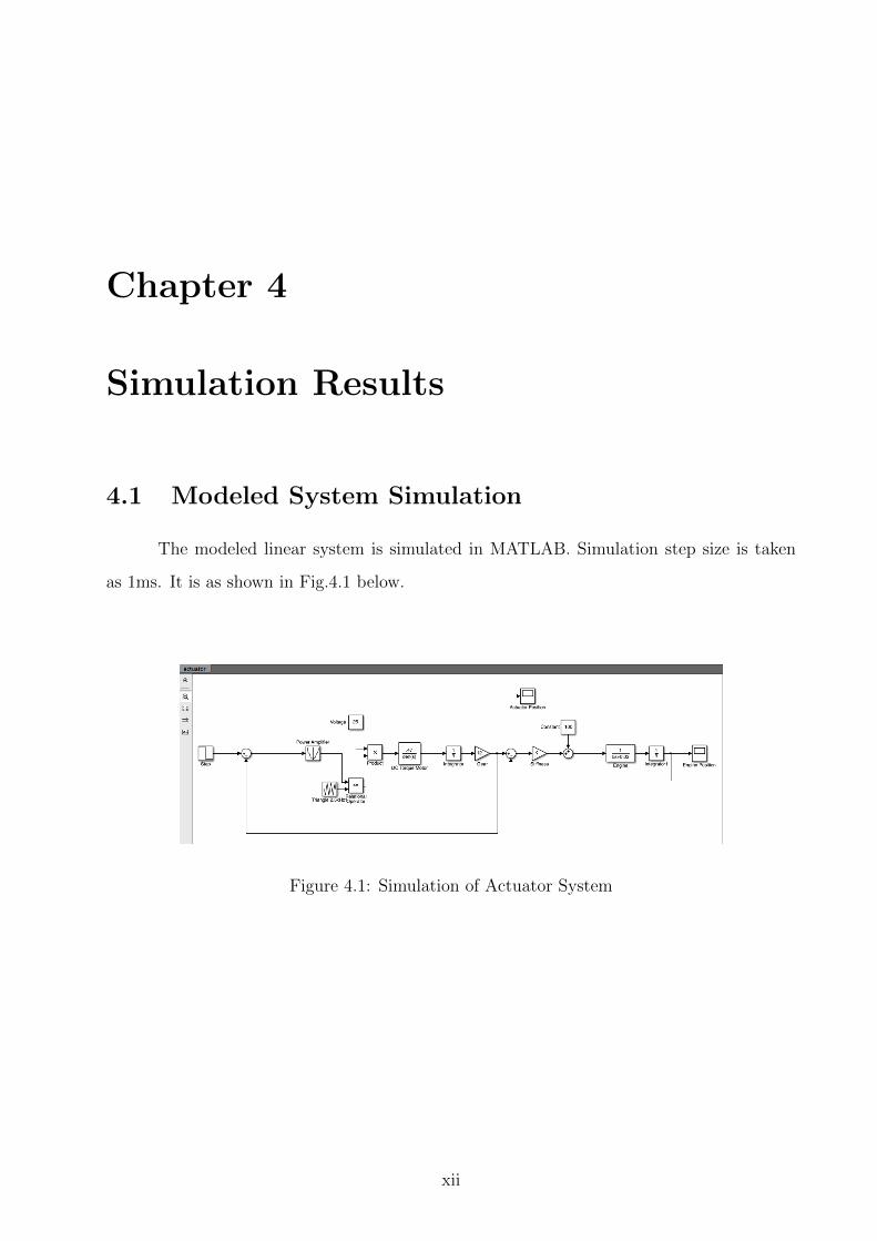
Chapter 4
Simulation Results
4.1 Modeled System Simulation
The modeled linear system is simulated in MATLAB. Simulation step size is taken
as 1ms. It is as shown in Fig.4.1 below.
Figure 4.1: Simulation of Actuator System
xii
Page 19
The results are shown below as in 4.2, 4.3.
Figure 4.2: Actuator Position
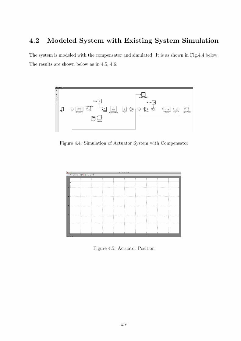
Figure 4.3: Engine Position
xiii
Page 20
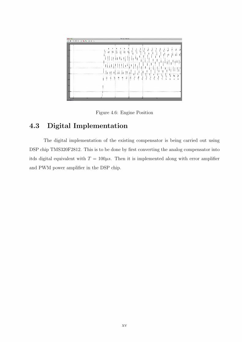
4.2 Modeled System with Existing System Simulation
The system is modeled with the compensator and simulated. It is as shown in Fig.4.4 below.
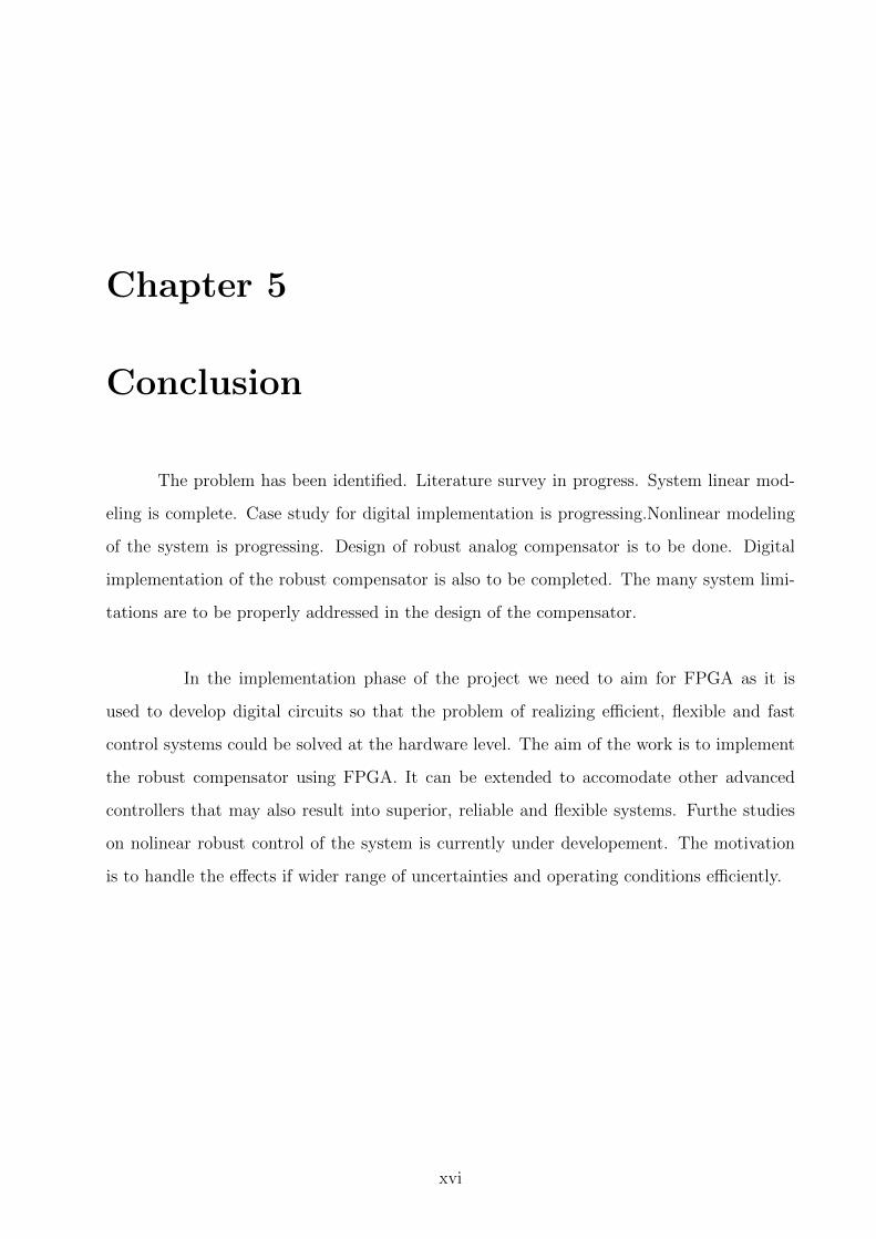
The results are shown below as in 4.5, 4.6.
Figure 4.4: Simulation of Actuator System with Compensator
Figure 4.5: Actuator Position
xiv
Page 21
Figure 4.6: Engine Position
4.3 Digital Implementation
The digital implementation of the existing compensator is being carried out using
DSP chip TMS320F2812. This is to be done by first converting the analog compensator into
itds digital equivalent with T = 100µs. Then it is implemented along with error amplifier
and PWM power amplifier in the DSP chip.
xv
Page 22
Chapter 5
Conclusion
The problem has been identified. Literature survey in progress. System linear mod-
eling is complete. Case study for digital implementation is progressing.Nonlinear modeling
of the system is progressing. Design of robust analog compensator is to be done. Digital
implementation of the robust compensator is also to be completed. The many system limi-
tations are to be properly addressed in the design of the compensator.
In the implementation phase of the project we need to aim for FPGA as it is
used to develop digital circuits so that the problem of realizing efficient, flexible and fast
control systems could be solved at the hardware level. The aim of the work is to implement
the robust compensator using FPGA. It can be extended to accomodate other advanced
controllers that may also result into superior, reliable and flexible systems. Furthe studies
on nolinear robust control of the system is currently under developement. The motivation
is to handle the effects if wider range of uncertainties and operating conditions efficiently.
xvi
Page 23
References
1. Mohamed A. Darwish, Hossam S.Abbas, “ DC Motor Speed and Position Control Using
Discrete-Time Fixed-Order H∞ Controllers”, International Journal on Information
Management, vol. 1, no. 1, December, 2012.
2. Kiam Heong Ang, Gregory Chong, Yun Li,” PID Control System Analysis, Design
and Technology”, IEEE transactions on Control System Technology, vol 13, no.4, pp
559-575,July 2005.
3. S. Ghosh, R.K. Barai, S. Bhattarcharya, P. Bhattacharyya, S. Rudra, A. Dutta, R.
Pyne, “An FPGA based implementation of a flexible digital PID controller for a motion
control system”, Proceedings of IEEE International Conference on Computer Commu-
nication and Informatics, Coimbatore, January, 2013.
4. Y.Y. Tzou, T.S. Kuo, “Design of a FPGA based position PI servo controller for a
DC motor with dry friction”, Proceedings of IEEE VII Southern Conference on Pro-
grammable Logic, pp. 75- 80, 2011.
5. Y.Y. Tzou, T.S. Kuo, “Design and Implementation of an FPGA-Based Motor Control
IC,” Proceedings of IEEE International Conference on Industrial Electronics Control
and Instrumentation, vol. 2, pp. 943-947, 1997.
6. Y. Li, S. Zhuang, L. Zhang, “Development of an FPGA-Based Servo Controller for
PMSM Drives,” Proceedings of IEEE International Conference on Automation and
Logistics, pp. 1398-1403, August, 2007.
7. V. Subasri, K. Lavanya, B. Umamaheswari, ” Implementation of Digital PID Controller
in Fixed Programmable Gate Array”, Proceedings of India International Conference
xvii
Page 24
on Power Electronics, pp. 172-176, 2006.
8. Rene Cumplido, Simon Jones, Roger M.Goodall, Stephen Bateman, “ A high per-
formance processor for embedded real time control”, IEEE Transactions on Control
System Technology, vol 13, no.3, pp. 485-492, May 2005.
9. Yankai Xu, Kai Shuang, Shan Jiang, Xiaoliang Wu, ”FPGA Implementation of a Best-
precision Fixed-point Digital PID Controller , Proceedings of International Conference
on Measuring Technology and Mechatronics Automation, pp. 384-387, 2009.
10. K.Shuang, Y.K. Xu, S.Jiang, “Converting Analog Controllers to Digital Controllers
with FPGA”. Proceedings of 9th International Conference on Signal Processing, pp.486-
489, October, 2008.
11. Y. F. Chan, M. Moallem, W. Wang, “Efficient implementation of PID control algorithm
using FPGA technology,” Proceedings of the 43rd IEEE Conference on Decision and
Control, Bahamas, vol.5, pp. 4885-4890, 2004.
12. Ba-Hai Nguyen, Hai-Bac Ngo, Jee-Hwan Ryu, ”Novel Robust Control Algorithm of
DC Motors”, Proceedings of 6th International Conference on Ubiquitous Robots and
Ambient Intelligence, pp.120-122, 2009.
13. C.P. Diduch, R. Doraiswami, ”Robust Servomechanism Controller Design for Digi-
tal Implementation”, IEEE Transactions on Industrial Electronics, vol IE-34, no.2,
pp.172-179, May, 1987.
14. Safanah M. Raafat, Rini Akmeliawati, Ismael Abdulljabaar, ”RobustH∞ Controller for
High Precision Positioning System, Design, Analysis and Implementation”, Scientific
Research Journal on Intelligent Control and Automation, vol. 3, pp. 262-273, July,
2012.
15. Jose L. Tong, James P. Bobis, ”A Model for Designing Digital PID Controllers”, IEEE
Transactions on Control System Technology, pp. 1157-1162, 1995.
16. Horng J.H., ” Neural Adaptive Tracking Control of a DC Motor”, Information Science,
vol. 118, pp. 1–13, 1999.
xviii