Model for End of Life Treatment of Polymer Composite Materials ANNA HEDLUND-ÅSTRÖM Doctoral thesis Department of Machine Design Royal Institute of Technology SE-100 44 Stockholm TRITA – MMK 2005:23 ISSN 1400-1179 ISRN/KTH/MMK/R-05/23-SE
Transcript
Model for End of Life Treatment of Polymer Composite Materials
ANNA HEDLUND-ÅSTRÖM
Doctoral thesis Department of Machine Design Royal Institute of Technology SE-100 44 Stockholm
odel for End of Life Treatment of Polymer Composite Materials
nna Hedlund-Åström
octoral thesis
cademic thesis, which with the approval of Kungliga Tekniska Högskolan, will be presentedor public review in fulfilment of the requirements for a Doctorate of Engineering in Machine esign. The public review is held at Kungliga Tekniska Högskolan, Lindstedtsvägen 5, room 2 at 10.00 on the 21:st of October 2005.
Abstract Because of increasing environmental demands, especially on dealing with products end of life phase, product manufacturers and designers must consider the future disposal of their products. For conventional materials like steel and aluminium well-functioning recycling methods exists. This is not the case for structures of polymer composites, which are used more extensively, especially for structures like vehicles and vessels. Several techniques do exist but they are not yet commercially available. The current disposal methods of polymer composites are landfill and incineration. Polymer composites are materials, which consist of several materials like fibre, matrix, and additives. In the form of sandwich constructions also foam core material is added. This circumstance complicates the waste treatment of composite materials. In this thesis a model for assessing possible future waste treatment techniques for polymer composites including sandwich structures is presented. The model is meant to be used as an aid for preparing future disposal for end of life products for planning waste treatment and for facilitating communication in contacts with waste receivers. Recommendations for waste treatment have been formed for a number of polymer composites. These recommendations are based on the analysis of costs and environmental effects and they compare different scenarios for mechanical material recycling and energy recovery by waste incineration. The result of this study points out material recycling as the preferable method for the main part of the studied materials. But this recommendation is strongly dependent on type of virgin material replaced by the recycled material. Energy recovery can also be considered if the polymer composite waste replaces coal, which is non renewable. Though incineration will always result in a cost for the waste producer. In the recommendations mentioned above no information concerning implementation of the different waste disposal techniques is included. Therefore, in this study a model for assessing possible waste disposal techniques for polymer composites is presented. The model is based on internal factors, which are related to the waste and to the processes. To implement the model relevant waste properties must be identified in order to fulfil the conditions set by the required processes involved. A case study was carried out using the proposed model for assessing different waste disposal techniques for the hull of the Visby Class Corvette in the Royal Swedish Navy. Six different techniques were studied for the hull structure. Since almost all the important waste properties were known and the waste was assessed to be treatable all the included techniques except one are shown to be usable in the future. Many investigations have pointed out material recycling as the best alternative considering environmental effects. This is also valid for polymer composite materials. Since recycling polymer composites is a complicated process, especially recycling thermoset composite it is important to aquire comprehensive information about the constituents of these materials. Keywords: polymer composites, material recycling, energy recovery, environmental effects, recommendations, waste treatment model
I
II
Acknowledgements The work presented in this thesis has been performed at the former Department of Aeronautics, Division of Light Weight Structures and at the Department of Machine Design, Division of Engineering Design, Kungliga Tekniska Högskolan. First I would like to thank my supervisors starting with Prof. Jan-Gunnar Persson for letting me finish my work at the division and for all support. Many thanks to Asc. Prof. Conrad Luttropp for accepting to guide and inspire me, and most important of all, for supporting and believing when times got tough. I want to thank all my former and present colleagues, Bo Magnusson, Ingela Hallonblad, Malin Åkermo, Per Wennhage, Jessica Lagerstedt, Anne-Marie Åkermark, Ulrika Forsberg, Jesper Brauer, Jan Johansson, Kjell Andersson and Carl-Johan Sjöstedt. Not to forget all friends round the coffee table from other divisions. My thoughts often goes to Prof. Karl-Axel Olsson, Mr sandwich himself, for giving me the opportunity to start working with waste disposal of sandwich constructions and also for encouraging me towards working with environmental issues. During these years I have had close contact with Per Reinholdsson, who I want to thank for many interesting discussions during my work. I also want to thank Gunilla Hugosson and Christina Sternerup for valuable support. Parviz Ahari, I am very grateful for the valuable work with reviewing my text. My mother Wivi and father Olle (I whish you could have experienced this) as well as my sister Maria and brother Pelle with family thank you for being there. Finally, I would like to thank those who are the most important in my life, my husband Per and our children Johan and Kristina. Anna Hedlund-Åström Stockholm, september 2005
III
IV
Content Abstract I Acknowledgement III Content V 1 Introduction 1 1.1 Background 1 1.2 Purpose and goal 2 1.3 Objective and scope 3 1.4 Research Questions 3 1.5 Scientific Approach 3 1.6 Thesis structure 4 2 Environmental context 7 2.1 General 7 2.2 Waste considerations 10 3 Polymer composite materials 13 3.1 Product life cycle for composite products 16 3.2 Methods of end of life treatment: state of the art 19 4 VAMP 18 project – recycling and recovery
of polymer composite materials 27 4.1 Outline of the project 27 4.2 Included materials 29 4.3 Results of the inventory and case studies 30
5 Forming recommendations for material recycling and
energy recovery 39 5.1 Goal and scope definition 39 5.2 Establishing of scenarios 40 5.3 Inventory and valuation 42 5.4 Recommendations 53 5.5 Sources of error 54 6 A model for end of life treatment of polymer composites 57 6.1 Influencing factors 59 6.2 A model for waste treatment 61 6.3 External factors 65 7 End of life process scenarios 69 7.1 Reuse 70 7.2 Mechanical material recycling 71
V
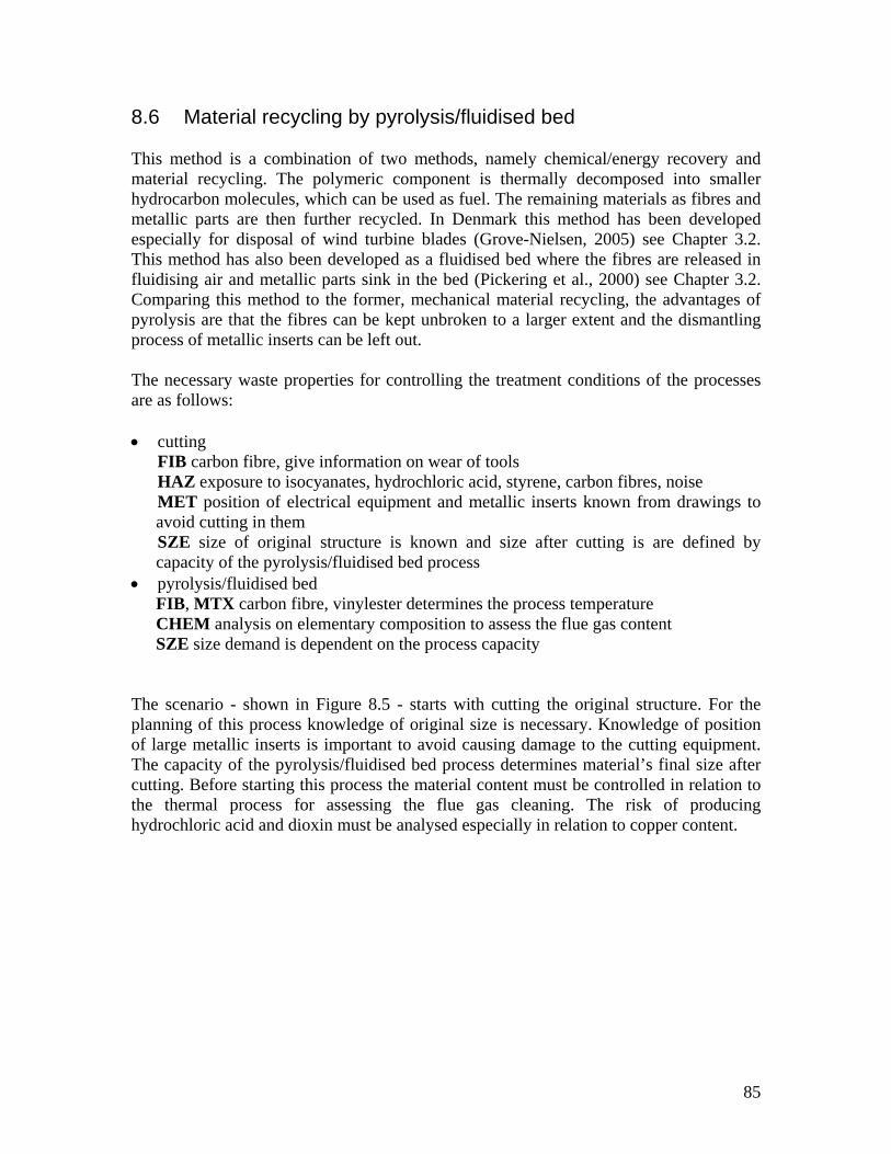
7.3 Material recycling and energy/chemical recovery by fluidised bed and pyrolysis 73
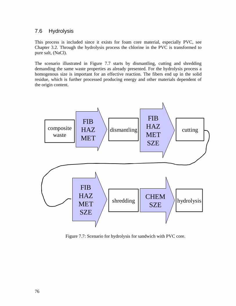
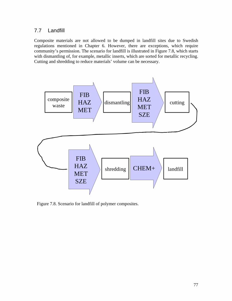
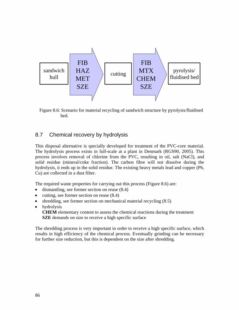
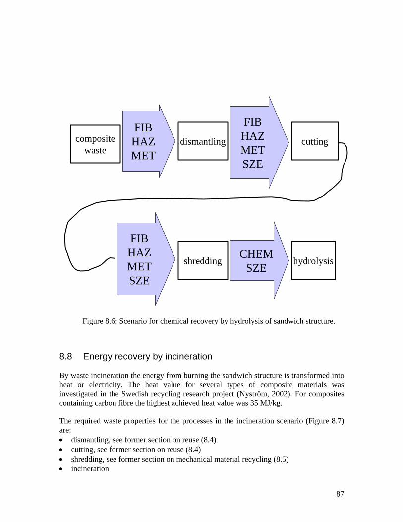
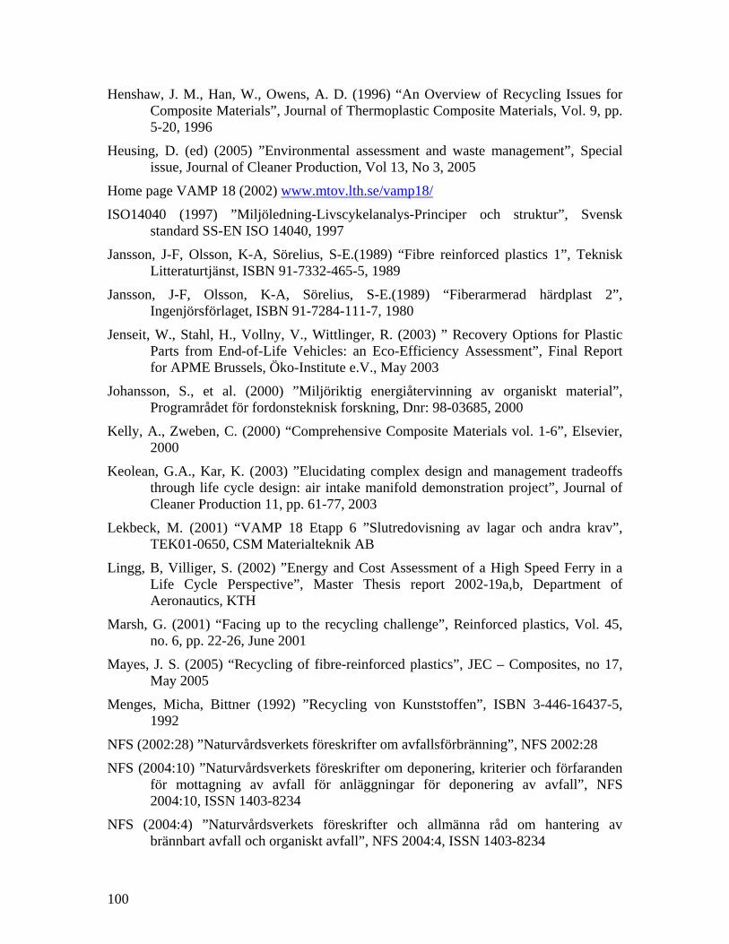
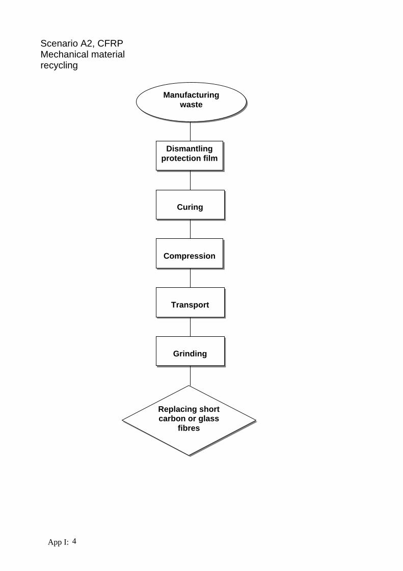
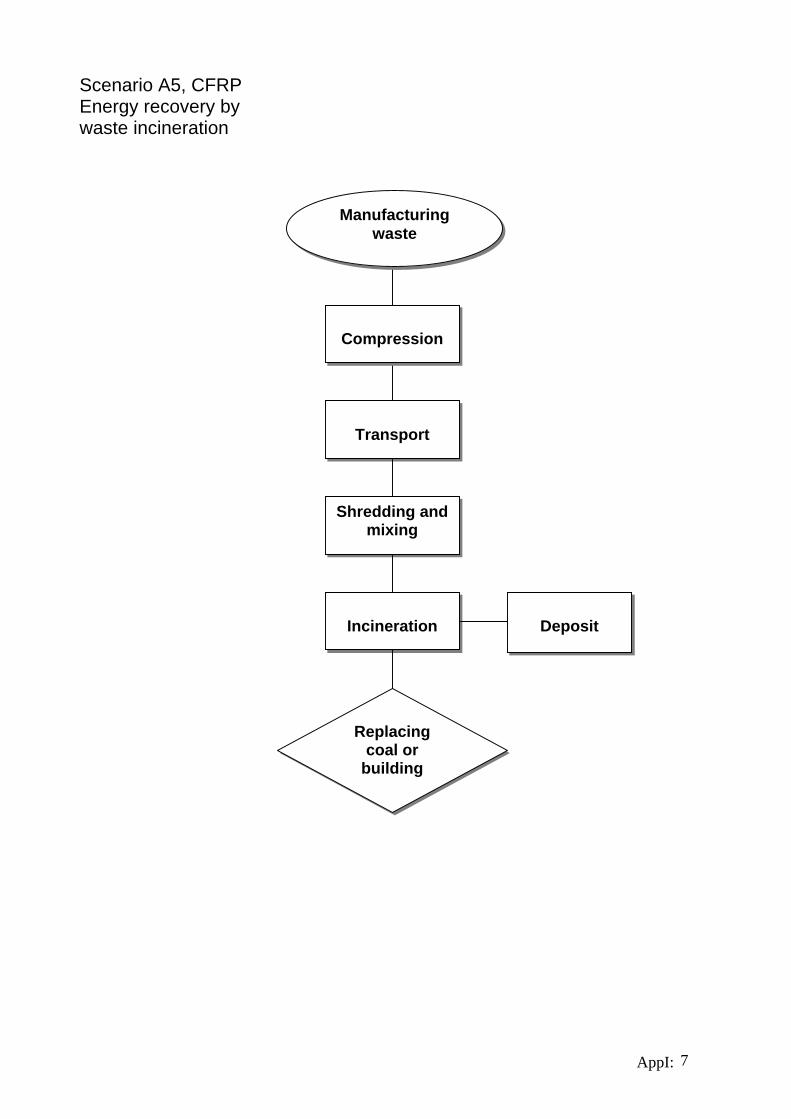
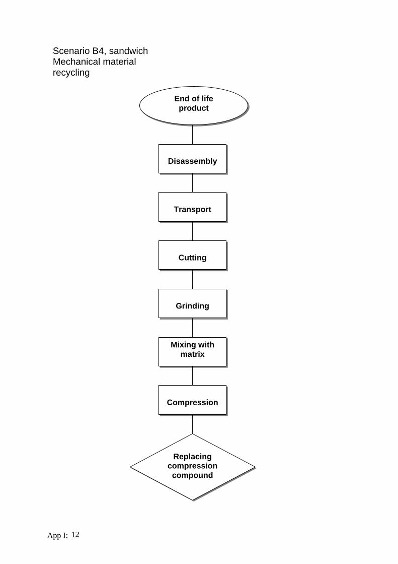
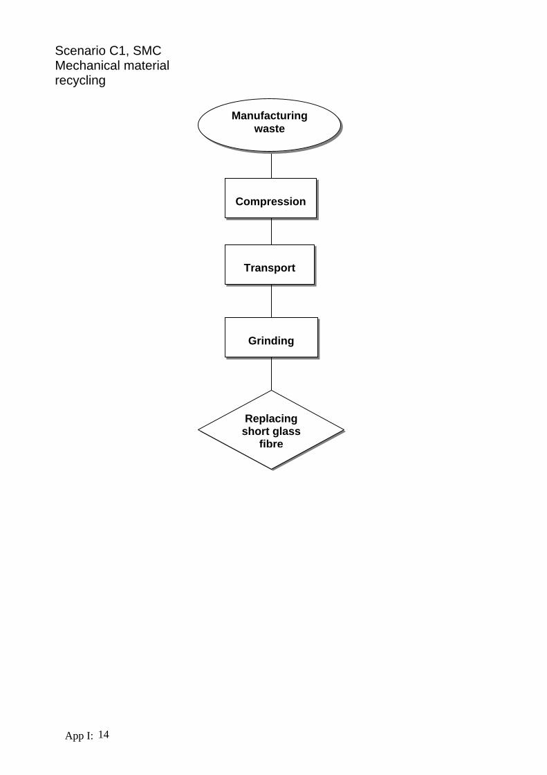
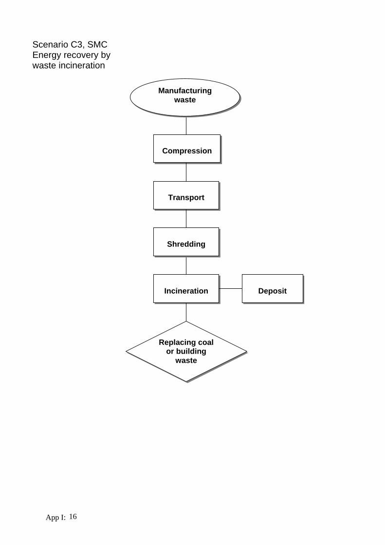
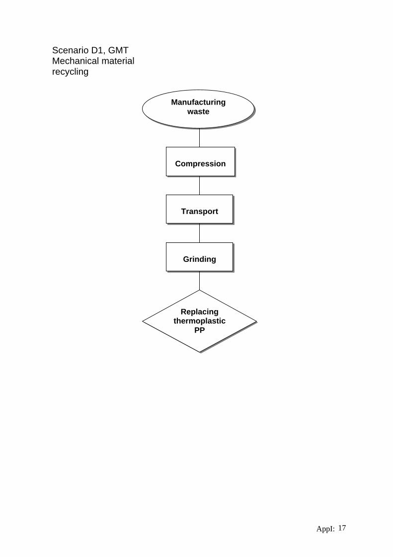
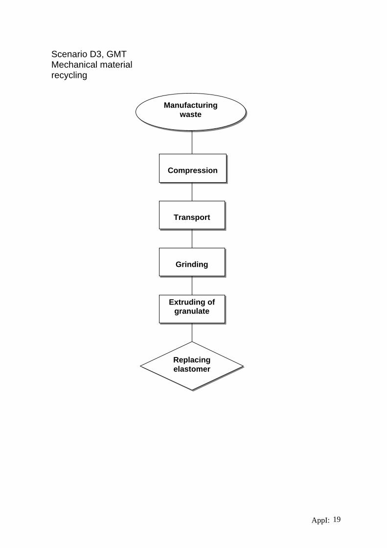
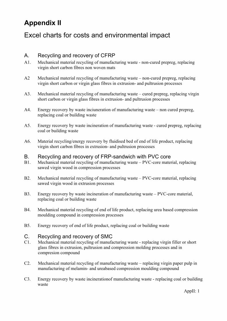
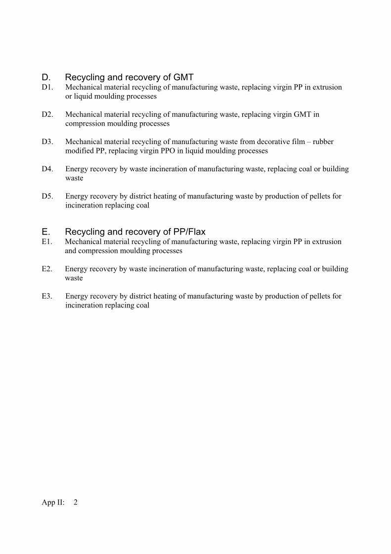
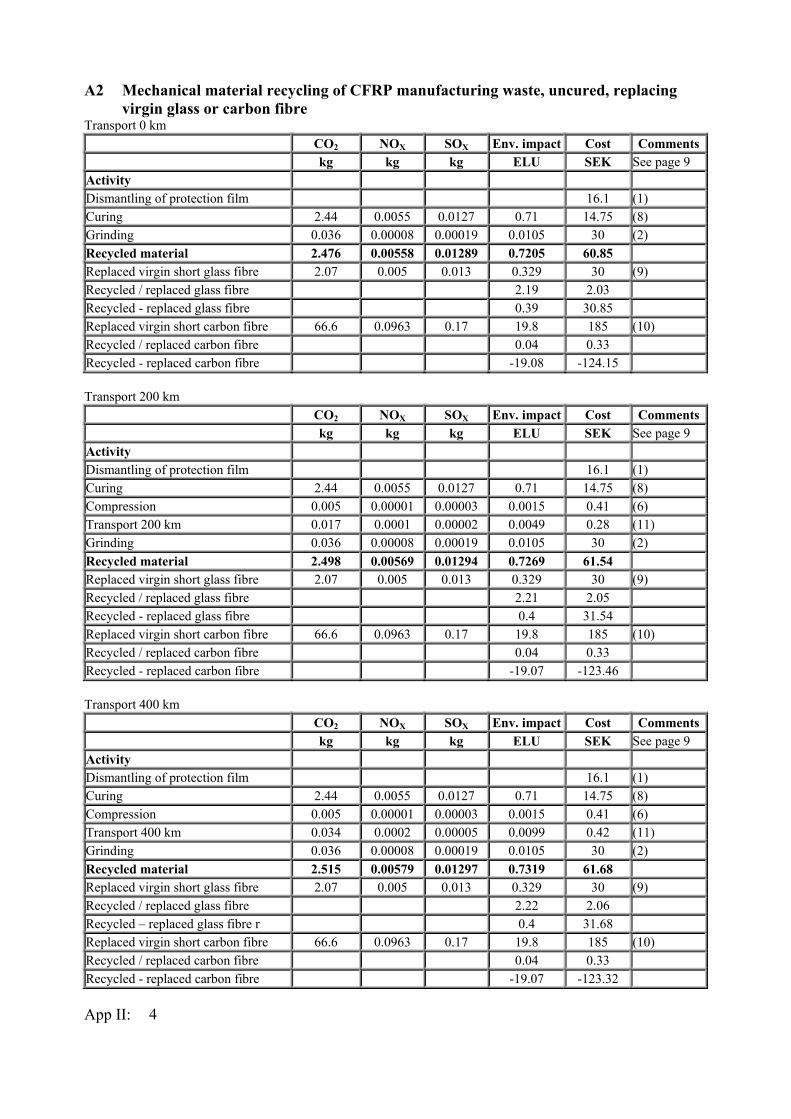
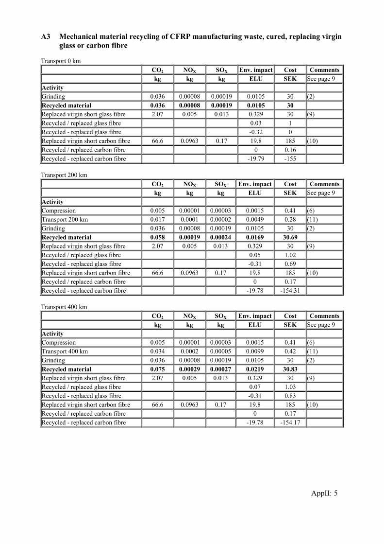
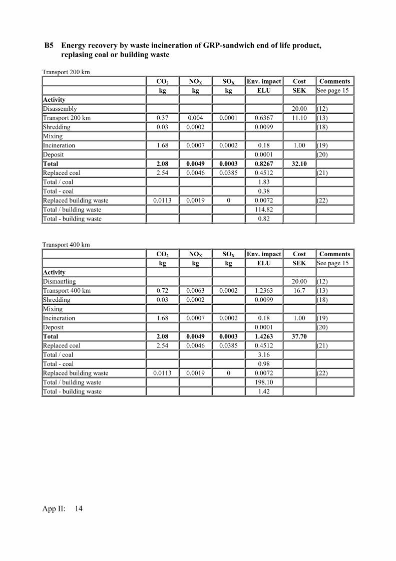
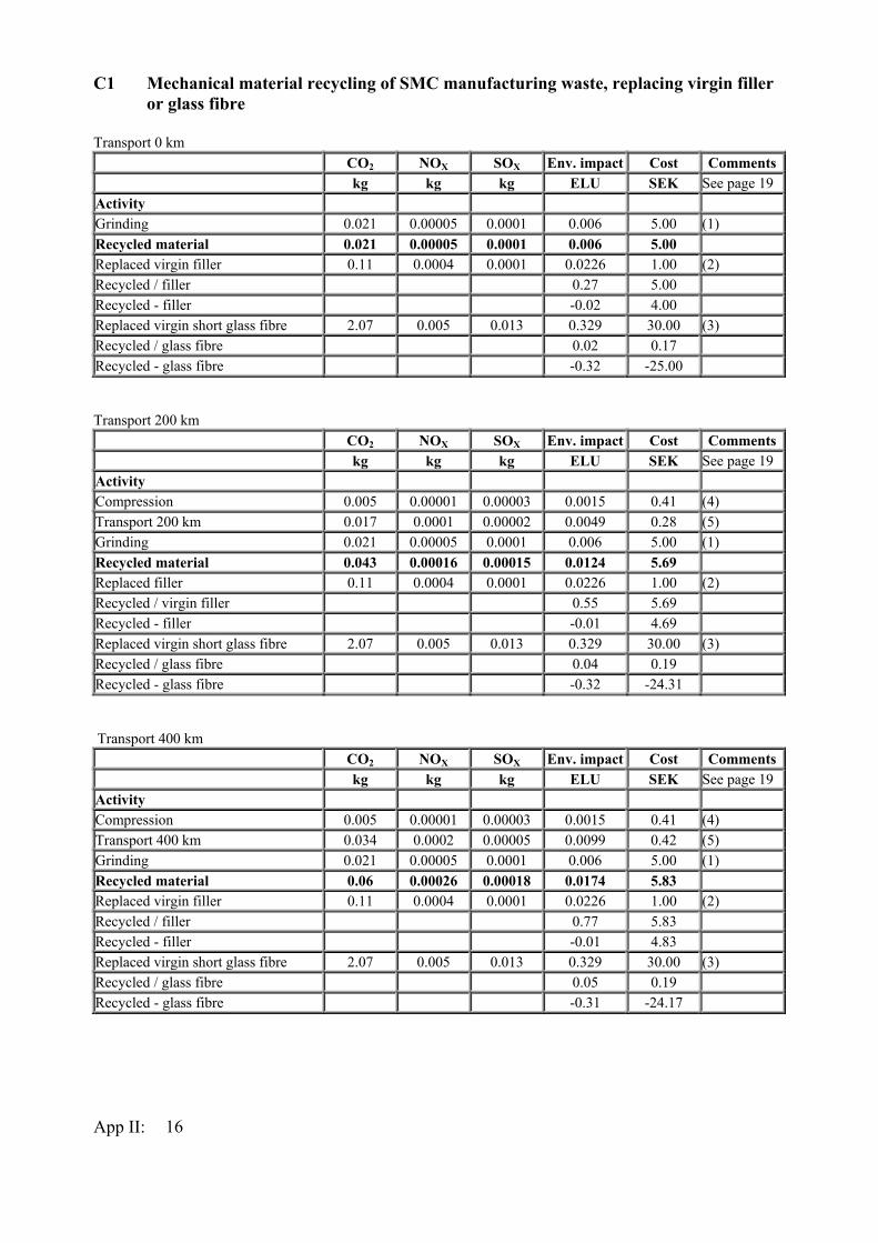
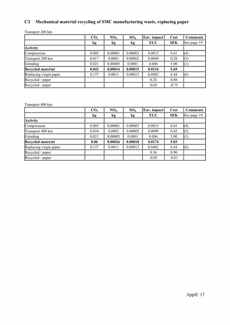
7.4 Material recycling by cement manufacturing 74 7.5 Energy recovery 74 7.6 Hydrolysis 76 7.7 Landfill 77 8 Case study – possible treatment of end of life sandwich ship hull 79 8.1 Introduction 79 8.2 Description of the Visby Class Corvette 80 8.3 Waste properties for Visby hull 81 8.4 Reuse 82 8.5 Mechanical material recycling 83 8.6 Material recycling by pyrolysis/fluidized bed 85 8.7 Chemical recovery by hydrolysis 86 8.8 Energy recovery by incineration 87 8.9 Landfill 89 8.10 External factors 90 9 Discussion, conclusion and future research 93 10 References 97 Appendix I: Scenarios A. Scenarios for material recycling and energy recovery of CFRP B. Scenarios for material recycling and energy recovery of FRP-sandwich with PVC core C. Scenarios for material recycling and energy recovery of SMC D. Scenarios for material recycling and energy recovery of GMT E. Scenarios for material recycling and energy recovery of PP/Flax Appendix II: Excel charts for costs and environmental impact A. Material recycling and energy recovery of CFRP B. Material recycling and energy recovery of FRP-sandwich with PVC core C. Material recycling and energy recovery of SMC D. Material recycling and energy recovery of GMT E. Material recycling and energy recovery of PP/Flax
VI
1 Introduction 1.1 Background Polymer composite materials exhibit excellent strength and stiffness in combination with low density. These properties are especially attractive in structures where transport of goods and people using non-renewable fuels are utilized. Decreased weight with equal transport capacity lowers the total cost and fuel consumption. For several years now glass fibre composites have been used in products such as containers, pleasure boats and automotive parts. Traditionally carbon and aramid fibre composites are utilised in more demanding applications like aircraft and aerospace industry. In these products the economic demand for saving weight is large and the higher cost for carbon fibre is then justified. The pressure from authorities to reduce CO2 emissions for reducing the greenhouse effect has raised the interest for composites, including carbon fibre, in automotive applications. A new composite material, advanced sheet moulding compound (ASMC) (Stachel & Schäfer, 2004), has been introduced on the market. This material is especially developed for exterior car body parts and contains both glass and carbon fibres. By using carbon fibre a weight reduction of 60% compared to steel and a weight reduction of 30% compared to aluminium is possible. This increased use of composites in industry with in production will create continuously more waste to be handled in the future. Also for this type of materials several regulations put pressure on producers to consider the waste treatment. Examples are prohibition against landfill, producer responsibility for specific groups of products such as vehicles, and eventually taxes on waste incineration, for example in Sweden. All these regulations are aiming for material recycling, due to decreased environmental impact. A common opinion is that recycling thermoset polymer composite materials will be especially difficult or not even possible. This is true at the moment, though research on development of technology and methods for polymer composite recycling has been ongoing for approximately 15 years. No market for recycled composite materials exists yet. To form a market several preconditions must be met. These involve among others, issues related to infrastructure, amount of material, recycling technology and applications. All these preconditions have not been met yet, however actions must be taken due to existing and forthcoming regulations. Polymer composite material is a relatively new group of materials and therefore they have not yet gained the same amount of utilisation as metallic materials. Since the composites also consist of a mixture of several types of materials on macro level they cannot be regarded as homogenous as the steel materials. Both these circumstances complicate the possibilities to form a well-organised system for waste handling. Attempts have been made, but they have failed due to lack of demands as one of several causes. The main alternative used today for handling composite waste is landfill but also waste incineration is an alternative. To respond to environmental awareness in society and to regulations, companies require new methods for waste disposal. Hence, in Sweden a research project for investigating methods for waste treatment of polymer composites has
1
been implemented. The aim was to form recommendations for material recycling and energy recovery based on analysis of economy and environmental effects. In the initial phase of the project, an inventory of existing techniques for waste treatment, existing and expected amount of waste and regulations was compiled. Materials considered were polymer composites with glass, carbon and flax fibres and polymer matrixes in thermoset and thermoplastic together with one sandwich structure including glass fibre thermoset and PVC core. The selected methods for further investigations by means of case studies were mechanical material recycling and energy recovery by waste incineration. For these methods the costs are analysed from the waste producers perspective and the environmental effects are analysed by application of life cycle assessment, LCA. The results indicated material recycling, assuming replacement of virgin materials, as being the best choice in both economical and environmental terms for almost all types of materials that have been studied. These results are strongly dependent on the choice of virgin materials replaced by the recycled materials. Energy recovery by waste incineration is also an alternative, as long as the replaced fuel is non-renewable, oil or coal. Waste treatment of polymer composites is more complex, compared to recycling of steel and aluminium, since they contain a mixture of materials with a multitude of combinations of fibres and polymer matrixes. In addition, for sandwich constructions there is also the core material to consider. The recommendations presented by the Swedish project do not include any information regarding details for carrying out the different waste treatment methods. Therefore a model has been proposed were especially technical information on processes as cutting, shredding and incineration are systematised. This model is based on the so-called internal properties of the structure, which are defined by the waste and process properties. 1.2 Purpose and goal The purpose of the model approach in this work is to facilitate planning of waste treatment for polymer composites. In this model waste treatment methods, which mainly exist in research environments, are gathered in a systematic way. The model is designed to be useful in developing waste treatment plans for currently existing polymer composite products and to facilitate communication in contacts with future waste handling companies. The overall goal of the study is to support future planning of waste treatment for composite wastes, to meet more demanding regulations, and to overcome the common opinion that it is impossible to recycle composites. To verify the proposed model, a case study should be carried out. The polymer sandwich hull structure of the Visby Class Corvette in the Royal Swedish Navy has been chosen as a relevant case. By identifying the necessary waste properties for the hull, several methods for waste disposal are assessed with the model.
2
1.3 Objective and scope The model should be based on the internal properties that are closely interrelated and are defined as waste and process properties. Depending on the type of waste disposal, different processes could be involved and therefore information on different waste properties is necessary. The objective is to identify and correlate necessary information (waste properties) for each step (process) in order to implement relevant waste treatment processes. The following delimitations have been made for the development of a polymer composite waste disposal model. In the model the waste is assumed already being disassembled into parts. The structure is then free from components and assemblies, which can be easily removed with tools without penetrating the structure. Details for dismantling like metallic inserts and electrical wires in the structure, as well as surface treatment, are included in the model. Interrelations between the different steps and management of waste handling from end of life products to final fraction are not covered. The model concentrates on necessary and sufficient information that is needed for a single process step. For working environment regulations only Swedish regulations are included. 1.4 Research question • How can a model be organised for handling relevant information in waste disposal of
polymeric composites? • What could be a feasible structure of the model and how could this model be used? 1.5 Scientific approach This research started in the research project "Riktlinjer för återvinning av fiberkompositer" (VAMP 18) financed by Vinnova. The comprehensive empirical results from this project show a need for a model to handle necessary information in the context of different waste handling processes. Such a model is presented in this thesis and the model is tested in making the waste-handling scenarios for the Visby Corvette (Combat Ship Swedish Navy). In the VAMP 18 research project, economical and environmental impact analyses are made. For the environmental impact evaluation the Life Cycle Assessment (LCA) method is used based on the EPS method (Steen, 1999). The study is made as a screening LCA and the EPS 2000 Design System, which includes the data base (Assess, 2001) was used due to it’s practical approach. The goal was to achieve recommendations to practical engineers. Totally 22 waste handling scenarios were formed for the analysis, see Appendix I & II. In the assessment of waste handling scenarios a so-called consequential
3
LCA methodology is applied. A straightforward concept was decided to use, which illustrates “what-happens-if”. The relevant alternative replaced virgin material or fuel where decided within a reference group in the VAMP 18 research project. For both the economical analysis and LCA information on costs and environmental information are provided by companies participating in the VAMP 18 project, from outside the project and research reports. The environmental impact inventory data for the life cycle assessment (LCA) is collected from the EPS 2000 data base and from companies participating in the VAMP 18 project and from outside the project. Also data is produced by tests within the project and calculations made based on data from tests. From these results recommendations are formed for a number of polymer composite materials. However, these recommendations do not provide any detailed information, for the waste producer and receiver, on the technology to be used for the treatment of the material. Within the VAMP 18 project a lot of knowledge is gained, which is not possible to include in that type of analysis made for forming the recommendations. Therefore a model is developed, based on properties, which are set by the processing techniques involved in the waste treatment methods. To meet these processing demands specific and more detailed characteristics of the waste must be identified. The information in this thesis is gathered from the VAMP 18 project together with the connected recommendations and on reported experience from small-scale research investigations to full scale industrial applications for handling of polymer composites. On this base a scenario building model is suggested. This model is then used for scenario building for the different disposal alternatives for the Visby Class Corvette. 1.6 Structure of the thesis The environmental background including the historical perspective regarding waste handling is described in Chapter 2. The underlying problem resulting in need for research due to increased consumption, energy use and the resulting environmental effects, climate changes and resource scarcity are described. In Chapter 3 polymer composite materials are briefly described in terms of constituent materials, properties and areas for utilisation. The potential for decreasing costs and environmental impacts by using of polymer composites is presented through examples of implemented life cycle studies. In the final section a presentation is made on state of the art of the waste treatment methods for composite materials. In Chapter 4 the work of the Swedish project, VAMP 18, on recycling and recovery of polymer composites is presented. Since the main parts of the reports from this project and the project web site is in Swedish, a short version in English is provided. The materials studied in the project are presented and the work done on material recycling and energy recovery is described. The aim of the VAMP 18 project was to form recommendations for recycling and recovery.
4
These recommendations are based on analysis of costs and environmental effects for different scenarios, which are presented in Chapter 5. All scenarios and related tables with compiled data on costs and emissions are presented in Appendix I and II. After presentation of the resulting recommendations for each type of the investigated composite materials, chapter 5 is concluded with a discussion of the sources of errors in the analysis. The recommendations formed in the former chapter do not consider any details for the techniques of how to carry out the waste disposal. Therefore, a model based on the waste properties is suggested and presented in Chapter 6. In Chapter 7 the model is developed into scenarios for a number of waste disposal methods. Also the necessary waste properties are identified for each step (process) of the waste treatment methods. In Chapter 8 the proposed model is tested. The hull of the Visby Class corvette for the Royal Swedish Navy is used as case study. After identifying the waste properties, the scenarios for the possible waste disposal methods are discussed. Since nearly all the waste properties are known, several methods have been identified to be useful for the future disposal of the hull. The contributions of the thesis and suggestions for further research are presented in Chapter 9. In this thesis the end of life cycle phase is treated in isolation from the previous phases. In order to facilitate waste treatment, this phase must be considered when designing the product. Hence one suggestion for further research is to facilitate disassembly of complex products as vehicle structures consisting of several types of materials. Chapter 10 contains the list of references and finally Appendices I and II.
5
6
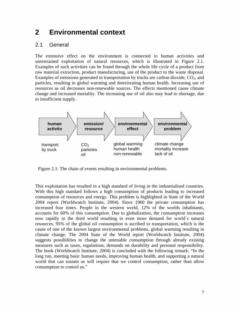
2 Environmental context 2.1 General The extensive effect on the environment is connected to human activities and unrestrained exploitation of natural resources, which is illustrated in Figure 2.1. Examples of such activities can be found through the whole life cycle of a product from raw material extraction, product manufacturing, use of the product to the waste disposal. Examples of emissions generated in transportation by trucks are carbon dioxide, CO2, and particles, resulting in global warming and deteriorating human health. Increasing use of resources as oil decreases non-renewable sources. The effects mentioned cause climate change and increased mortality. The increasing use of oil also may lead to shortage, due to insufficient supply.
TWc2ianrccsmTlwc
human activity
environmental effect
environmental problem
transport by truck
CO2 particles oil
global warming human health non-renewable
climate change mortality increase lack of oil
emission/ resource
Figure 2.1: The chain of events resulting in environmental problems.
his exploitation has resulted in a high standard of living in the industrialised countries. ith this high standard follows a high consumption of products leading to increased
onsumption of resources and energy. This problem is highlighted in State of the World 004 report (Worldwatch Institute, 2004). Since 1960 the private consumption has ncreased four times. People in the western world, 12% of the worlds inhabitants, ccounts for 60% of this consumption. Due to globalization, the consumption increases ow rapidly in the third world resulting in even more demand for world´s natural esources. 95% of the global oil consumption is ascribed to transportation, which is the ause of one of the known largest environmental problems, global warming resulting in limate change. The 2004 State of the World report (Worldwatch Institute, 2004) uggests possibilities to change the untenable consumption through already existing easures such as taxes, regulations, demands on durability and personal responsibility. he book (Worldwatch Institute, 2004) is concluded with the following remark: “In the
ong run, meeting basic human needs, improving human health, and supporting a natural orld that can sustain us will require that we control consumption, rather than allow
onsumption to control us.”
7
The overall awakening in society concerning environmental problems is ascribed to the current famous book “Silent spring” (Carson, 1962). In this book an accurate description of the harmful consequences for nature and humans due to spreading of the pesticide, DDT and other chemicals are provided. The resulting reactions in society in the 1960s principally dealt with local problems, for example, cleaning emissions to air from chimneys, and sewage from manufacturing industries to water. Over the last decades, knowledge of complexity and extent of the environmental problems has increased. From being concentrated on local problems the focus has changed to global problems and resulted in a new viewpoint, sustainable development. This concept was introduced by the World Commission on Environment and Development, WCED, in the Bruntland report (Bruntland, 1988). The aim of this concept is to reach balance between resource use and environmental impact, so that the environment is able to withstand the burden within the ecological cycle. At the same time the resource distribution should be fair. How to attain this global sustainability has been formulated through a number of conventions and agreements starting with the UN Conference on Environment and Development, UNCED, in Rio de Janeiro, 1992. One of the formulated documents is “Agenda 21” providing recommendations to countries and industry, (UN, 1992). In “Caring for the earth”, (UNEP et al. 1993), nine principles are formulated for creating a sustainable society. Here, ethics and other criteria to be fulfilled are defined together with the direction in which to work at individual, local, national and international level. The Swedish Parliament adopted in 1999 an environmental policy on fifteen environmental quality objects including clean air, high-quality ground water, no eutrophication, sustainable forests, a non-toxic environment, a protective ozone layer, limited influence on climate as example, (Swedish Environmental Protection Agency, 2005), . The goal is to achieve an ecologically sustainable society within one generation by year 2020, with exception of the climate objective – to be achieved by 2050. The fifteen objects are based on the following five principles, which are stated in the Swedish Environmental Code (SFS, 1998): promote human health
• preserve biological diversity • preserve cultural and historical assets • maintain the long-term productive capacity of ecosystems • ensure prudent management of natural resources
Many of the environmental goals, especially climate goals, within the EU countries are difficult to reach due to the considerable increase in transports of passengers and goods (EEA, 1999). Concerning the passenger transports the increase in engine effectiveness is not enough, because:
• people travel more, kilometer per passenger increase • people use bigger cars • travelling by air and car increases
8
For transport of goods, transport by rail and shipping is transferred to road transport. Emissions of greenhouse gases within EU are estimated to increase by 6% from 1990 until 2010. The concepts “Factor 10” and “Factor 4” have been formulated with the aim of describing quantitatively sustainable development in relation to consumption, resources and the number of people on the earth. Factor 10 is based on the fact that the consumption in OECD countries (Organisation for Economic Cooperation and Development) is 5 times higher than in developing countries. This means that a five-time decrease of consumption necessary for creating fairness all over the world. At the same time the material turnover must decrease by 50% to minimise the environmental effects. The result is a ten-time decrease in material utilisation for the OECD countries (Schmidt-Bleek, 1994). The Factor 4 advocates an efficiency increase by four times, doubling wealth while halving resource use (von Weizsäcker et al. 1997), including fifty examples of quadrupling the resource productivity. One of these examples concerns design of cars. In 1991 at Rocky Mountain Institute (RMI) a radical idea of redesigning a car from scratch was born. This idea resulted in the “hypercar”. By combining ultra-light and hybrid strategies the efficiency was estimated to increase up to five times compared to a normal passenger car. Ultra-light means here that the structural material is changed from steel to advanced composite as carbon fibre composite. The energy comes from an internal combustion engine, gas turbine or fuel cell with electric motor, including electric recovery of the braking energy in a hybrid-electric drive train. Several other examples deal also with increasing the overall transport efficiency, such as videoconferences instead of personal business meetings, drinking locally produced blackcurrant juice instead of imported orange juice, car sharing and car free mobility. In Sweden, the near future of transport systems has been investigated (Åkerman, et al. 2000). The results of this investigation point out the importance of breaking the trend of the increasing transport volume with cars in city traffic, trucks, and air transports. It is concluded that means of control supporting new concepts such as car sharing, small city vehicles, electrical bicycles, net shopping, and teleworking must be promoted in form of, for example, new taxes and environmental zones. In a study prior to the above mentioned, the future sustainable transport system until year 2040 was illustrated and investigated through a number of scenarios (Steen et al. 1997). Also here the change of structural material to lightweight polymer composite materials was discussed, although the recycling issue is questioned. During the nineties the environmental impact regarding the complete life cycle of a product has been highlighted (Ryding, 1995). Giving this overall picture, the largest environmental impact is related to the utilisation of many products. In production industry the environmental questions are therefore the focus of attention. Several new strategies for incorporating these issues into design have been developed under designation EcoDesign or design for environment (DFE). The purpose of these strategies (Åkermark, 2003a) are to:
9
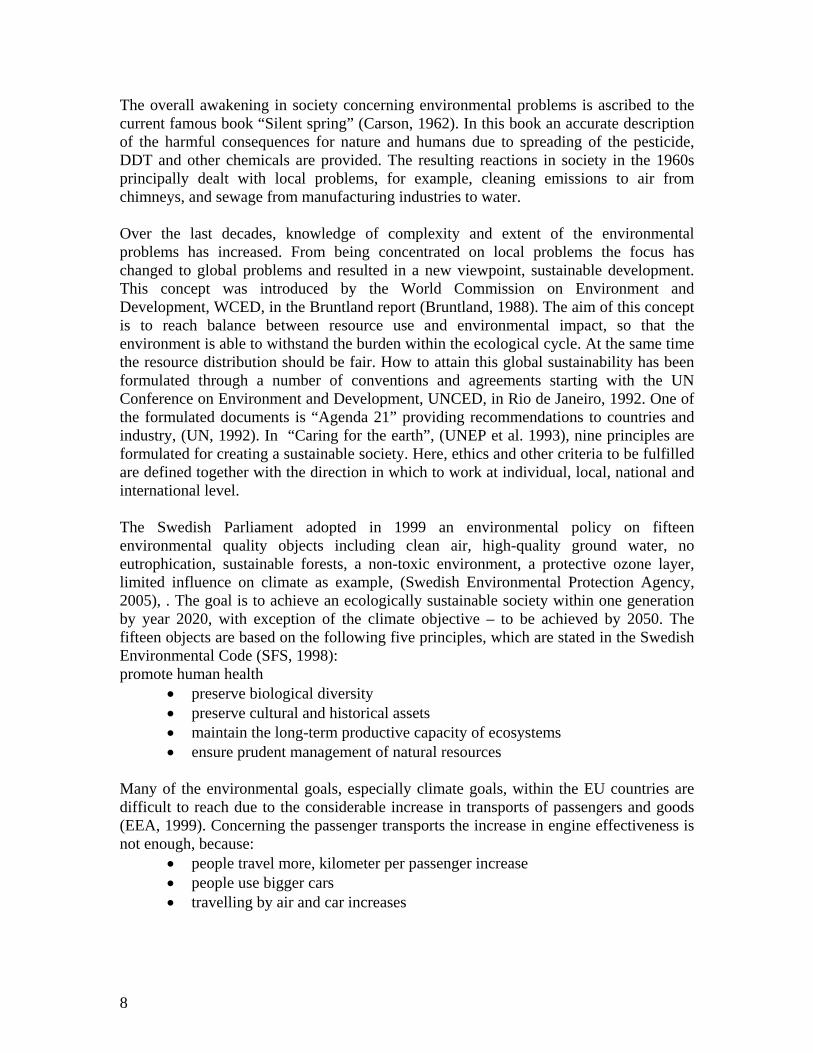
• minimise energy consumption • minimise use of material • exclude hazardous materials and substances • facilitate recycling 2.2 Waste considerations Following the increasing consumption the production of waste is also increasing. During 1990 to 1995 the generation of waste within the European Union (EU) had increased by 10%. The total amount of waste in year 1995 was 1,3 billion tons (agricultural waste not included) (EEA, 1999a). In the same study an estimate made for year 2010 showed that the waste will continue to increase. For example, the number of scrapped cars will increase by 35% until 2010, counted from year 1995. EU has identified seven key principles for waste management, see Figure 2.2 (EU, 2003).
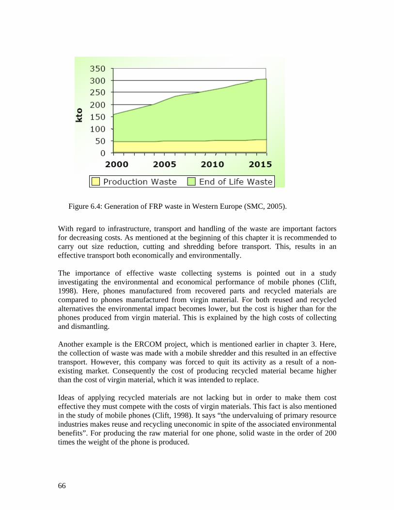
Figure 2.2: Seven key principles for waste management (EU, 2003). The first principle is the waste hierarchy described in Chapter 2.1. Landfill is still the common waste treatment in most EU countries. For municipal waste the trend during the nineties was an increase in landfill despite increased recycling, see Figure 2.3. This fact is explained by the low cost of waste incineration and landfill.
10
Figure 2.3: Waste treatment of municipal waste in EU during the 1990s (EEA, 1999a). This increase of landfill is exactly in opposition to the priority order according to the hierarchy for waste management, see Figure 2.2, regarding the environmental preferences (EU, 2003):
• prevention of waste generation • reuse of products • recycling • energy recovery • landfill
Landfill is the last option when all other alternatives have been considered. Several strategies in form of taxes and regulations have been formed to favour material recycling (SFS, 1998a). Examples are legislation to ensure producer responsibility for packaging material, paper, end of life vehicles and electrical and electronic waste. The relevance of the order within the waste hierarchy is often questioned. Several studies have been carried out to investigate the best alternative regarding environmental effects, using life cycle assessment (LCA) (Heusing, 2005). It is concluded that the waste management hierarchy can work well as a rule of thumb. However, the results of the investigations are strongly dependent on the external systems as energy systems, transports and time limit on landfill emissions. To handle the problem with the increasing amount of waste, one of four areas identified within the sixth environmental action programme of the European Union is to preserve resources and manage waste (EU, 2001). The aim is to reduce the amount of waste with 20% until 2010 and with 50% until 2050 based on the figures from year 2000. The other three areas are climate change, nature and biodiversity, and environment and health.
11
12
3 Polymer composite materials The word composite indicates a combination of at least two different materials. The two main components are polymer matrix and fibre. For a long time composite material as a structural concept has existed in forms of straw-brick, paper and reinforced concrete. However as natural material it has existed since almost the very beginning, for example, in form of wood and bone. But the polymer composites, presented here, belong to a relatively new group of industrial composites that have been in use since about half a century. What is specific for composites is that the structural material is produced at the same time the product is manufactured. By combining the two materials, fibre and matrix, unique properties are tailor made for the specific product. Strength and stiffness is obtained from the reinforcement, the fibres, which can be placed randomly or oriented in both continuous and discontinuous forms. The matrix situated between the fibres is meant to thoroughly surround and bind the fibres to transfer load and protect them against environmental influence. The interface between fibre and matrix is very important for the properties of the composite. In order to improve the adhesion the fibre is treated by means of different methods depending on the type of fibre, application of coupling agent or oxidising of fibre surface are two common methods. Examples of mostly used fibres are, glass, carbon, and aramid. Interest in natural fibres is increasing since they originate from renewable resources. Dependent on the matrix material, polymer composites are divided in two groups, thermoplastic and thermoset. The differences between these two groups are explained by the differences in their chemical structure. For thermosets, a three dimensional network of cross-linked polymer chains is formed during the curing process. This process is irreversible, that is, the material does not soften if it is heated. On the contrary, the reaction is different if thermoplastics are heated, they soften since no chemical reaction occurs. The mainly used thermoplastic matrices for composites are polypropylenes, polyamides, and polyketones. The commonly used thermoset matrices are unsaturated polyester, vinylester, epoxy, and phenolics. Together with the described constituent materials other substances are added. The aim with these additives are to improve the chemical processing and the final properties for the composite material. For the chemical process of curing several additives, for example, monomer (curing agent), initiator, and accelerator, are used. For unsaturated polyester the most common curing agent is styrene. Other types of additives that are not involved in the curing process are fillers, affecting mechanical properties, flame retardant for improving fire resistance, and pigments for giving colour. In structures where the demand is high stiffness in combination with low weight, an alternative to using high modulus fibre composites is to design the structure in composite sandwich. Compared to a single skin structure the sandwich alternative results in an increased flexural rigidity due to the sandwich effect. The bonding between the face and the core is very important to fulfil the properties of the sandwich. For sandwich
13
constructions, polymer composite faces based on either thermoset or thermoplastic matrices exist. The main core materials are expanded foams of polyvinylchloride (PVC), polyurethane (PUR), polystyrene (PS), honeycomb of corrugated metals or paper, and wood (balsa). The main advantages of composite materials, compared to competitive engineering materials, are the followings: • Low weight • High specific strength and stiffness (specific means normalised with density) • Good fatigue properties • Corrosion resistance • Electrical insulation • Sound and heat insulation • Easy to design complex shapes resulting in fewer details • Low maintenance Of course there exists also disadvantages, for example poor temperature tolerance and high cost, but the most important issue is that all the presented advantages are dependent on the choice of constituent materials and the manufacturing method. If not accurate choices are made, the final result can be fatal. Several manufacturing methods are available. The choice is dependent on the type of material, thermoset or thermoplastic, shape, performance and number of product units. For manufacturing of products in large amounts, automated processes with high productivity are required. Examples are moulding and compression techniques for applications in vehicles, as body panels, spoilers, bumpers and interior parts for cars, buses, and trucks. The most common constituent materials for body panels are glass fibre, filler and unsaturated polyester in form of the sheet moulding compound (SMC) and bulk moulding compound (BMC). But the use of high performance fibres as carbon, are advancing in vehicle design, resulting in lower weight and saving fuel. Within a EU project, TECABS (Technologies For Carbon Fibre Reinforced Modular Automotive Body Structures) the automotive industry together with suppliers and research institutes have developed a carbon fibre floorpan with a reduction of weight around 50% and reduction of parts by 30% compared to an equivalent steel structure (Reinforced Plastics, 2004). The manufacturing technique used for the floor is resin transfer moulding (RTM), a closed method reducing the emissions during processing. In Figure 3.1 another example of carbon fibre in automotive is presented. The outer body of the Volvo Electric Concept Car, 3CC, is produced in carbon fibre in form of a one-piece shell. Interior parts are mainly manufactured in glass-mat reinforced thermoplastic (GMT), with polypropylene as matrix. But the use of natural fibre as flax, hemp, sisal and coconut is increasing and has been used for some years for vehicle interior parts. Recently, banana fibre was introduced in an exterior part, for the covering of the spare wheel recess, by Daimler Crysler, see Figure 3.1.
14
HamrcitAfmmr Oiaad
Figure 3.1: Examples on applications of banana fibre in Mercedes A Class and carbon
fibre composite in Airbus 380 and Volvo 3CC (Global composites, 2005).
igh performance products for aeronautics, aerospace, military, and sports applications re manufactured manually by hand lay-up techniques for small-scale production. Here ainly carbon fibre and epoxy matrices are used in form of pre-impregnated
einforcement, named prepregs. Curing is made in autoclaves and the final material, arbon fibre reinforced plastic, is designated CFRP. Examples of products are the wings n the Swedish combat aircraft Gripen, where composite materials account for 30% of the otal weight. Many examples can also be found in civil aircrafts. For example in the new irbus A380, which will be launched in 2006 the fuselage is manufactured in carbon
ibre composite see Figure 3.1. Totally 25% of this aircraft’s structure is in composite aterial of which 22% is based on carbon fibre. Examples in sports applications, among any others, are golf clubs, snow skis, surfboards, skateboards, bicycles, and tennis
acquets.
ne major consumer of glass fibre and unsaturated polyester composites is the marine ndustry, where they are used particularly in leisure boats. The manufacturing methods re mainly manual hand lay-up and spray-up. Also in more advanced marine applications nd in windmill structures composites are used in form of sandwich constructions. The evelopment of the FRP-sandwich technique started in the 1950s at KTH. In a joint
15
development programme the minesweeper Viksten was built in 1974 as the very first composite sandwich ship hull (Gullberg & Olsson, 1990). Today, after 30 years of development, the Visby Class Corvette, a stealth surface attack ship built for the Royal Swedish Navy is probably the largest carbon fibre composite structure in the world, containing 50 tons carbon fibres. For this structure a new manufacturing technique is used, namely vacuum injection moulding. This method is closed and meets the environmental demands concerning the monomer release of styrene (AFS, 2005). Manufacturers of leisure boats are also implementing this technique, which in addition to improved working environment also results in higher quality of the final product. Examples of other structural applications of polymer composites are bridges, containers, building panels, pipes, and pressure vessels. Applications, where the structural properties are not the main issue can be found in electric and electronic industry. For example, the electrical insulation property of composites is exploited in circuit boards, electrical equipment boxes, and cable trays. In the following literature further information on polymeric composite materials can be found. “Manufacturing of polymer composites” (Åström, 1997). This book covers all possible techniques for manufacturing of commercial composite materials together with an extensive presentation of constituent materials and also one chapter on the issue recycling. “Fibre reinforced plastics 1” (Jansson et al., 1989) and “Fiberarmerad härdplast 2”, (Jansson et al., 1980). The first book includes description of constituent materials and processing. In the second book structural design of both composites and sandwich constructions are included. “An introduction to sandwich construction” (Zenkert, 1995), gives a thorough description of the theory of design and analysis of sandwich structures. “Comprehensive composite materials vol. 1-6” (Kelly & Zweben, 2000). This set of six volumes includes mechanical and physical properties, theory, design, manufacturing, testing and application for polymeric, metal, ceramic and concrete based composites. 3.1 Product life cycle of polymer composite products As presented in the opening of this chapter, polymer composites present many favourable properties, if the constituent materials and manufacturing method are properly utilised. The main property of interest is the low density, which results in high specific strength and rigidity. The largest field of application is therefore transport, including vehicles on land, at see and in air. Since the largest part of the costs and environmental impact is caused in the usage phase of the products, there are several driving forces, whose aim is to decrease the weight of the products. Lower structural weight can be utilised in form of increased transport capacity, longer transport distances, or decreased fuel consumption. In the end this will result in decreased cost and decreased environmental impact per
16
conveyance of goods. Several life cycle studies show this benefit of polymer composites compared to other structural materials. In a master thesis (Lingg & Villiger, 2002), three different structural materials are compared over their life cycle in three high-speed ferries. These materials were steel, aluminium and sandwich construction with carbon fibre composite. The comparison includes both costs and energy consumption over materials’ life cycle. For the sandwich alternative the structural weight of the ferry was decreased by 30% compared to the steel version, resulting in a decrease of both energy consumption and costs with 20% over the life cycle. The analysis points out the composite structure as the best choice considering the economy over the life cycle, see Figure 3.2. However, the energy consumption is slightly higher for the composite structure in comparison with the aluminium version. This is explained by the large energy consumption for the manufacturing of carbon fibre. For this type of structure more than 99,5% of the total energy consumption originates from the use of the structure where the fuel is consumed.
Figure 3.2: Accumulated costs of the three high-speed ferry alternatives(Lingg & Villiger, 2002).
69.0 69.1 74.2
352.8
273.0 254.7
-0.3 -0.9
6.3 6.4 6.0
0.0
-50.0
0.0
50.0
100.0
150.0
200.0
250.0
300.0
350.0
400.0
450.0
Steel Aluminium Composite
ME
uro
DisposalOperation and maintenanceProductionPlanning and design
This has also been demonstrated in an earlier investigation, a comparative Life Cycle Assessment (LCA) study for a coast guard vessel (Hedlund-Åström & Olsson, 1998). During the operation phase of the ship 99,7% of the total environmental impact was produced. Here an aluminium hull was compared to a glass fibre sandwich hull. The result pointed out sandwich as the best alternative with totally 6 % lower environmental impact over the life cycle.
17
Also in automotive applications the environmental effects during operation totally dominate all other environmental effects that are generated in other phases of products’ life cycle, such as in production and disposal. Approximately 80% of the total environmental effect originates from driving cars and the rest is divided among material and product manufacturing and waste treatment (Baumann et al., 2002). In the following a number of LCA studies are presented where polymer composite materials, which are used in automotive structures, are included. As pointed out earlier these materials are preferable from the life cycle perspective compared with other structural materials. One study compares zinc-covered steel plate with GMT, which are found in the front parts of cars (Ryding et. al. 1995). In the composite alternative the weight is reduced by 40%, which results in 50% decrease of environmental effects compared with the steel version of the same parts. In the second example, for a deck lid, three materials are compared, steel, aluminium and SMC (Schmidt & Handels, 2004). Also here the low weight material SMC presents the lowest total environmental impact. In the third example, different types of polymer composites are compared, which are thermoplastic and thermoset glass fibre composites, GMT and SMC in a car front. The GMT part presents the lowest weight and thereby decreased environmental impact (Berglund & Lundström, 1996). The interest in using natural fibre to substitute glass fibre has increased, because natural fibre has lower density and originates in renewable resources. A comparison of these two materials in respect to the environmental effects reveals that the natural fibre composite is more beneficial in automotive products (Satish et al, 2004). An example of an LCA study concerning a non-moving structure is a propane cylinder where a glass fibre composite is compared to the traditional materials steel and aluminium (ASSESS, 1999). Also here the result showed that the composite alternative has the lowest environmental impact, which is explained by its low weight and longer life length in corrosive environment. From these studies concerning the entire life cycle of products it can be concluded that the polymer composite materials are beneficial especially where low weight is an important issue. A further step related to the above mentioned comprehensive life cycle studies is to integrate specific requirements considering environmental performance into product design, namely life cycle design (LCD). In a study comparing three material alternatives, where one is a polymer composite material, for an air intake manifold (Keolean & Kar, 2003), LCA and LCC analysis are made together to a LCD. The LCD framework includes 20 performance requirements, to evaluate the alternatives. Examples of requirements, which are not considered in LCA and LCC analysis are feasibility of
18
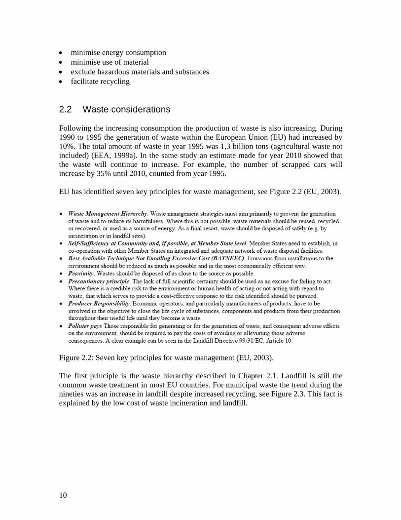
manufacturing, regulations, and business policies. The result of the study points out several positive attributes of each manifold, although the composite alternative presents the lowest weight and energy consumption over the life cycle. For evaluating the best disposal technique for composite parts from end of life vehicles seven products were investigated with an Eco-Efficiency-Analysis method (Jenseit et al, 2003). The method combines LCA with economic analysis. The best alternatives for the most of the parts are material recycling and energy recovery options. Mechanical material recycling is the best choice for parts, which are easy to dismantle. This fact is also mentioned in a study of vehicle recycling from a designer perspective (Åkermark, 2003). In order to enable for composite parts to be recycled major design changes are necessary. On the other hand the former investigation (Jenseit et al., 2003) shows that the operation results in considerable environmental impact, which means that the design should focus on and optimise the operation phase instead of just considering the end of life stage. In Figure 3.3 the decrease in weight and the resulting fuel saving by use of composite materials are illustrated.
Figure 3.3: Possible savings of fuel acar (APME, 2003).
3.2 Methods of end of life trea Since the beginning of the 1980s reseatechniques for disposal of waste from clandfill is the most common method landfill sites is now prohibited in Swedcountries according to the EU directivehas been created to focus just on recycliregarded as a great social problem (Msummarising studies of recycling metho
s a result of decrease in weight of the
tment: state of the art
rch has been carried out to investigate possible omposite structures. Still, as already mentioned,
of waste disposal. Landfill of organic waste in en and Germany and it will be soon in other EU s (Council directive, 1999). In Japan a committee ng of waste from thermoset composites since it is ayes, 2005). A number of comprehensive and
ds - especially concerning thermoset composites -
19
have been accomplished to demonstrate the possibilities and to meet the future legislation requirements (Mayes, 1999), (Olsson & Törnsten, 1992), ( Hedlund-Åström et al., 1994), (Åström, 1997), (Henshaw et al., 1996), (Simmons, 1999), (Derosa et al., 2005), (Marsh, 2001). Based on these and on more specific studies an overview of the methods is provided. The methods are divided into the following groups: • reuse • mechanical material recycling • energy recovery • material recycling and energy or chemical recovery Reuse Since thermoplastic materials can be melted, reuse by reshaping is a possible method of recycling thermoplastic composites. However, re-melting causes degradation of the matrix which must be considered (Olsson & Törnsten, 1992), (Åström, 1997), although studies of reshaping thermoplastic materials have shown improved properties of these materials because of better impregnation (Åström, 1997). Another option to be considered is reuse after repair. Mechanical material recycling Mechanical material recycling is one of the most investigated methods and it is also the only method, which is commercially exploited for recycling polymer composites. Generally this method involves a series of mechanical processes, such as cutting, shredding, grinding, and milling, resulting in a step by step reduction of material size. In order to minimise wear of knives, metal components should be removed before grinding or milling. After processing the material can be sorted in several fractions, which varies from powder to different fibre lengths and can be used as filler or reinforcement. Mechanical recycling has been implemented commercially in Germany by ERCOM Composites Recycling (ERCOM, 1991), (Buhl & van Paumgartten, 1992), which was founded in 1990 by material suppliers and composite material producers. A complete recycling concept was developed for the thermoset composite material - sheet moulding compound (SMC) – which is used (among others) for manufacturing automotive parts and telecommunications products such as telephone kiosks and cable boxes (Weaver, 1994). The wasted parts were collected by a mobile shredder, which resulted in a reduction of volume and in a cost effective transport to a central processing plant. At the processing plant the shredded material was ground by a hammer mill and metals were separated magnetically and by gravitational means. Eight different material fractions were produced, varying from powder to fibres of several mm length, which can be used in new composite products and replace virgin filler and fibre material. Unfortunately the activities have been discontinued since the process was not economically viable. A similar method of recycling production waste is used in France by Mecelec - a company, which produces moulding compounds such as SMC and bulk moulding compound (BMC), which are used for manufacturing parts for automobiles and electrical components (Weaver, 1995). There are also corresponding organisations in France such as ERCOM, Valcor (which began its production in 1994), and in USA such as the R.J. Marshall company (Simmons, 1999).
20
The ground material is after processing mixed with virgin material resulting in a new composite material. The quality and the technical performance of mechanically recycled material have been demonstrated in several projects during the last decade. Recycled thermoset composites are used in manufacturing of SMC, BMC and thermoplastic products as GMT. One example of an application is a leisure boat manufactured by spray up processing (Pettersson & Köllerfors, 1997) see Figure 3.4. In this example the original single skin structure is replaced with a sandwich structure where the core contains 40% by weight of recycled material.
Generally when recycled material replaces virgin material, mechanical properties such as stiffness and strength are reduced. This has been shown in several studies by replacing both virgin filler and fibre material with recycled material (where recycled material content is up to 30% by weight) (Mayes, 2005), (Olsson & Törnsten, 1992), (Hedlund-Åström et al., 1994), (Åström, 1997), (Derosa et al., 2005a). However by replacing virgin filler material in SMC with up to 20% recycled filler the resulting SMC prove to have lower weight with comparable mechanical properties to the virgin alternative (Marsh, 2001).
Figure 3.4:Leisure boat containing recycled material (Pettersson & Köllerfors,
1997).
Several studies have been carried out to investigate the cause of the reduction of material properties when recycled material is substituted for virgin material. Since during recycling the material is treated mechanically, the complete composite structure, that is, matrix, fibre, and fibre-matrix interface can be affected. In one study micrographs of BMC containing recycled material are investigated, and based on this study it is concluded that the reduction of material’s properties can be
21
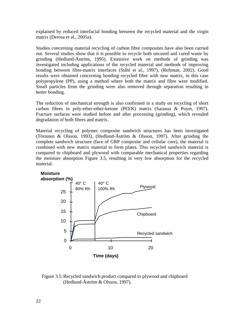
explained by reduced interfacial bonding between the recycled material and the virgin matrix (Derosa et al., 2005a). Studies concerning material recycling of carbon fibre composites have also been carried out. Several studies show that it is possible to recycle both uncured and cured waste by grinding (Hedlund-Åström, 1995). Extensive work on methods of grinding was investigated including applications of the recycled material and methods of improving bonding between fibre-matrix interfaces (Ståhl et al., 1997), (Reftman, 2002). Good results were obtained concerning bonding recycled fibre with new matrix, in this case polypropylene (PP), using a method where both the matrix and fibre were modified. Small particles from the grinding were also removed through separation resulting in better bonding. The reduction of mechanical strength is also confirmed in a study on recycling of short carbon fibres in poly-ether-ether-ketone (PEEK) matrix (Sarasua & Poyet, 1997). Fracture surfaces were studied before and after processing (grinding), which revealed degradation of both fibres and matrix. Material recycling of polymer composite sandwich structures has been investigated (Törnsten & Olsson, 1993), (Hedlund-Åström & Olsson, 1997). After grinding the complete sandwich structure (face of GRP composite and cellular core), the material is combined with new matrix material to form plates. This recycled sandwich material is compared to chipboard and plywood with comparable mechanical properties regarding the moisture absorption Figure 3.5, resulting in very low absorption for the recycled material.
ard
2
Time (days)
0
5
10
15
20
25
0 10 20
Chipboard
Plywood
Recycled sandwich
40° C 80% Rh
40° C 100% Rh
Moisture absorption (%)
Figure 3.5: Recycled sandwich product compared to plywood and chipbo
(Hedlund-Åström & Olsson, 1997).
2
Almost exclusively mechanical material recycling has been investigated with respect to production waste since this material is generally free from surface treatment and filth. Another aspect (of production waste) is that this material has not been affected by ageing as products that are used for several years. End of life products may also contain hazardous substances such as heavy metals, which should not be used further in new products. In a work on glass fibre reinforced polyamide 66 (used for automotive applications) both, degradation due to the recycling process and the effects of use of the product on material properties were investigated (Eriksson, 1997). Both, recycled material from manufacturing waste and end of life waste were shown as valuable materials for further use. But the recycled material from end of life waste is recommended for use in applications with lower strength demands than strength demands on the origin material. For manufacturing waste the reduction of mechanical properties can be coupled with process induced fibre breakage. For waste from end of life products degradation in the matrix was demonstrated. Also the influence of impurities was studied, resulting in the conclusion that relatively large impurities could be accepted without significant decrease in mechanical properties. Regarding recycling of already recycled material an investigation (where glass fibre thermoplastic was injection moulded repeatedly four times) resulted in gradual decrease of strength and modulus after every recycling procedure (Graham et al., 1993). Energy recovery A common way of waste treatment is waste incineration and recovery of the heat or just reduction of the volume of the waste. Polymer composites represent an appreciable energy content. But the energy content is dependent on type of composites. For polymer composites containing inorganic materials (glass fibres and filler) the energy content is lower and thereby the ash content is higher. Some investigations concerning the prerequisites for using composites as a fuel were carried out in the Swedish research project VAMP 18 (presented in the following chapters 4 and 5). At the same time an investigation of energy recovery by incinerating different composites (used by the automotive industry) was made by Volvo (Johansson et al., 2000). In the Volvo study a classification of additives in composites was also made together with life cycle assessment of the emissions from the incineration. Based on the results the recommendation is to blend composite material (10% by weight) with ordinary waste as building waste or municipal waste to keep the limits on emissions and to improve dismantling technique regarding electrical cables, rubber, and chlorine content in plastics. The SMC composite material is discussed to determine whether it is appropriate for incineration regarding the high ash content (70- 80%) and low heat value, which is below the heat value of municipal waste.
23
Combination of material recycling and energy recovery or chemical recovery The following methods represent a combination of material recycling and energy recovery or chemical recovery. Mainly, the aim of these methods is to remove the matrix in order to free the fibres and to use them for material recycling. Through chemical recovery the polymer molecules are depolymerised into substances with lower molecular weight which can be used for producing new polymers or fuel for heat or electricity production. Here a number of different techniques exist (Menges et al., 1992). Pyrolysis and hydrogenation are thermal methods resulting in hydrocarbons and/or an oil fraction, while hydrolysis, alcoholysis, and glycolysis are chemical methods where the polymer chains are decomposed into monomers. Pyrolysis is the mostly investigated method for some years now for recycling/recovery of polymer composites. Several industrial plants exist all over the world for treatment of wasted tyres. The thermal decomposition of the organic material takes place in the absence of oxygen resulting in liquid (oil) and gaseous (hydrocarbons) components which both can be used as fuels. The gaseous fraction can also be used for manufacturing new chemicals. Several different composite materials with matrices such as phenolic, polyester, vinylester, epoxi, and polypropylene reinforced with glass and/or carbon were investigated at temperatures from 350°C to 800°C by pyrolysis (Cuncliffe et al., 2003). From mechanical tests it is concluded that the strength of materials reduces with increased treatment temperature. From investigations of SMC pyrolysed at several temperatures (de Marco et al., 1997), (Torres, 2000) the followings are concluded: • temperatures from 400°C to 500°C are suitable • the recycled fibres can be reused in BMC, resulting in comparable properties to those
of virgin BMC • the gas fraction is sufficient to produce for energy to the process plant • of the liquid part 40% can be used as petrol, and 60% can be used together with fuel
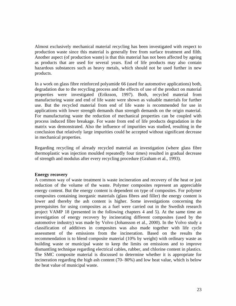
oils Corresponding results are obtained in an investigation of pyrolysis of glass fibre reinforced polyester (GRP) (Cuncliffe & Williams, 2003). The amount of 20% by weight of virgin glass fibre was replaced in BMC (with recycled fibres). An example of this process (with commercial plans) for treatment of polymer composite waste has been developed in Denmark especially for wind turbine blades (Grove-Nielsen, 2005). After size reduction the waste is placed in a chamber where the matrix is gasified at 500°C and distributed to an afterburner at 1000°C where energy is produced. Remaining materials in the chamber are fibre, filler, and metal (see Figure 3.5), which are further recycled. The fibres are ground and can then be used as insulation material or as short fibres in new composite products.
24
Figure 3.5: From rotor blade to fibre, filler and metal (Grove-Nielsen, 2005).
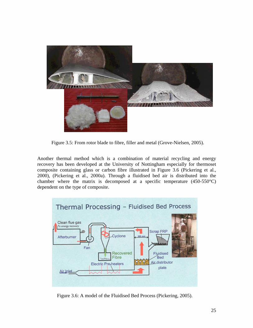
Another thermal method which is a combination of material recycling and energy recovery has been developed at the University of Nottingham especially for thermoset composite containing glass or carbon fibre illustrated in Figure 3.6 (Pickering et al., 2000), (Pickering et al., 2000a). Through a fluidised bed air is distributed into the chamber where the matrix is decomposed at a specific temperature (450-550°C) dependent on the type of composite.
Figure 3.6: A model of the Fluidised Bed Process (Pickering, 2005).
25
The fibres and fillers are transported by the air into a cyclone and the organic gases are further transported for energy recovery. Metallic parts sink down in the fluidised bed. An economic estimate of this process for glass fibre points out 10 000 ton per year as the break even point resulting in a cost of the recycled fibre which is 80% of the cost of virgin fibre. Tests of fibre strength of the recycled carbon fibres show that their strength is up to 80% of the strength of virgin fibres and their stiffness remains unchanged. This fluidised bed process was also investigated in the VAMP 18 project for carbon fibre composites with honeycomb core, see Chapters 4 and 5. Here a reduction in fibre diameter was detected when compared to virgin fibres. In the USA Adherent Technologies Inc. (ATI) has developed a commercially available technique (low temperature pyrolysis) for recycling of carbon fibres (Ronald et al., 1996), (Boeing, 2003). The process is conducted in a reactor below 200°C in the presence of a catalyst. Examination of the fibre showed no damage after recycling and mechanical tests showed a 9% loss in strength compared to the virgin fibre. Compared to mechanical material recycling the advantages of these methods are that the fibres’ length can be kept unbroken to a larger extent and fibres are not mechanically affected so that more of the original strength can be utilised. Also the removal of metallic parts before the treatment is not necessary compared to mechanical recycling. Expanded foams of polyurethane (PUR) and polyvinyl chlorine (PVC) are used in structural composites as sandwich constructions. Hydrolysis for recovery of PUR foams was investigated by Ford and General Motors in the 1970s (Henshaw et al., 1996). The most common core material in sandwich structures used for structural applications is expanded PVC. In Denmark a hydrolysis process has been developed especially for treatment of PVC waste (RGS 90) (RGS 90, 2005). The PVC containing waste is reduced in size and mixed with spent sodium hydroxide. The liquid mix is then hydrolysed in a pipe-reactor at a temperature of 260°C, producing pure salt and solids. Other treatment methods of polymer composite waste deal with using waste in cement manufacturing. In production of cement the glass fibre and filler replace the raw materials clay and limestone. The polymeric matrix material replaces fuels in the energy demanding process where temperatures reach up to 2000°C. Also this method is a combination of material recycling and energy recovery. This process requires a large steady supply of material. At the moment this method is evaluated in France (Scori, 2005), presenting promising results. Specific processing demands are: • no metallic parts • no chlorine • size demands (90% > 10 mm, 100% < 50 x 50 x 20 mm)
26
4 VAMP 18 project – recycling and recovery of polymer composites
In this section a Swedish project, which investigated the possibilities for material recycling and energy recovery of fibre reinforced polymeric composite materials is presented. The project was financed by the Swedish Agency for Innovation Systems and by the participating companies. Duration of the project was three years, from February 1999 until March 2002. The main reason for starting this project was to meet the future changes in legislation for disposal of waste. Product manufacturers that use FRP-composite materials also felt pressure from customers, who required relevant waste handling solutions. The aim of the project was to create recommendations for material recycling and for energy recovery based on economical and environmental analysis, thereby also a comparison of the alternative treatments could be done. Anna Hedlund-Åström was responsible for the analysis of the economical and environmental investigations. 4.1 Outline of the project A survey of the sequence of work within the project is presented in Figure 4.1. Participants in the project were nineteen Swedish companies and seven universities and institutes. The companies mainly comprised product manufacturing industries using FRP-composite materials and companies with knowledge of materials’ end of life treatment. Participating companies in the project were: Applied Composites AB Assess EcoStrategy Scandinavia AB CSM Materialteknik AB DIAB AB Hägglunds Vehicle AB Jomill AB Lear Corporation Sweden Interior Systems AB Maskin AB Rapid Nimbus Boats AB Perstorp AB Polytec Composites Sweden AB ProEngCo Permedyn AB Saab Automobile AB Saab AB Saab Ericsson Space AB Scania AB Swedish Defence Material Administration Tekniska Verken i Linköping AB Volvo Cars AB
27
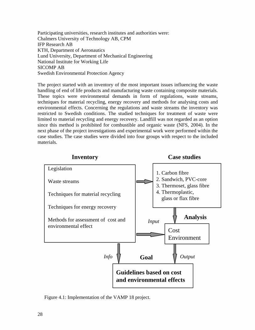
Participating universities, research institutes and authorities were: Chalmers University of Technology AB, CPM IFP Research AB KTH, Department of Aeronautics Lund University, Department of Mechanical Engineering National Institute for Working Life SICOMP AB Swedish Environmental Protection Agency The project started with an inventory of the most important issues influencing the waste handling of end of life products and manufacturing waste containing composite materials. These topics were environmental demands in form of regulations, waste streams, techniques for material recycling, energy recovery and methods for analysing costs and environmental effects. Concerning the regulations and waste streams the inventory was restricted to Swedish conditions. The studied techniques for treatment of waste were limited to material recycling and energy recovery. Landfill was not regarded as an option since this method is prohibited for combustible and organic waste (NFS, 2004). In the next phase of the project investigations and experimental work were performed within the case studies. The case studies were divided into four groups with respect to the included materials.
Guidelines based on cost and environmental effects
Goal
InputAnalysis
Inventory Case studies
Info Output
Legislation
Waste streams
Techniques for material recycling
Techniques for energy recovery
Methods for assessment of cost and environmental effect
Figure 4.1: Implementation of the VAMP 18 project.
Analysis of the costs and environmental effects were made parallel to the case studies. The costs of the different waste treatments were analysed from a waste producer perspective. The influence of the environmental effects was studied with Life Cycle Assessment (LCA) according to the standard ISO14040 (ISO14040, 1997). Based on the results of the analysis recommendations were formed for each material. All results of the project are presented at the home site www.mtov.lth.se/vamp18/. Also, a summarising inventory report is presented (VAMP 18, 1999). The results of the project have also been presented at international conferences (Hedlund-Åström, 2000), (Hedlund-Åström & Luttropp, 2003). In the following sections the included materials and results of the inventory and case studies are presented. 4.2 Included materials The following five types of polymeric composite materials were included in the project. • Carbon Fibre Reinforced Plastic (CFRP)
Carbon fibre is used in structures with high demands on strength and stiffness and is mainly combined with the polymeric matrix materials epoxy or vinylester. Carbon fibre composite is used in military structures such as aircrafts and in sport products such as golf clubs.
• Fibre Reinforced Polymeric (FRP)-sandwich and constituent PVC-core material
A sandwich construction contains a joining core between two faces. This combination of materials results in a structure with high bending stiffness. The type of sandwich investigated in the project contained cross-linked PVC as core material. The outer face material is made of FRP-composite material with fibres of either carbon or glass and matrix of polyester or vinylester. This type of sandwich structure is used for manufacturing of pleasure boats, large ships, and containers.
SMC is a thermoset polymeric composite material. The name of this composite originates in the manufacturing method, where a pre-impregnated sheet is formed, which contains glass fibre, polyester resin, and filler. Applications of SMC are body panels of vehicles and electrical components.
• Thermoplastic composite with glass fibre as Glass-Mat Reinforced
Thermoplastic (GMT) This material is comparable with SMC with the difference that the polymeric resin is thermoplastic polypropylene. Applications are non-visible and interior parts for vehicles.
• Thermoplastic composite with natural fibre as Polypropylene/Flax (PP/Flax) Instead of glass fibre in GMT this composite is reinforced with the natural fibre flax. This material is used for manufacturing of interior parts in vehicles.
4.3 Results of the inventory and case studies To survey the topic an inventory of the important issues concerning the possibilities of waste disposal was made. These topics are presented in figure 1 and they are further discussed here. Legislation One of the most important topics investigated in the inventory were laws and regulations influencing all waste treatment activities. Hence, environmental demands in form of both national regulations and EU-regulations was investigated and compiled, which includes the currently existing legislation and the expected future legislation (Lekbeck, 2001). The report includes also legislation concerning the working environment. Here a summary of the most important regulations is presented. According to the mentioned set of the rules, which deal with the external environment, the following conclusions concerning the polymeric composite materials can be drawn: - From January 2002 on polymer composite waste is regarded as plastic waste, since
plastic constitutes the main part of the composite - Possibilities of energy recovery are dependent regulations of the individual
incineration plants and their capacities - For transport of the composite waste across EU countries permission is necessary,
since polymer composites are not on the green list During the implementation of the project a Swedish group was studying, at the same time, the possibilities of changing the classification of some types of waste. According to this study the waste would represent an economic value to the waste producer if it was changed from being waste to raw material, which could be used for energy production. This study interesting for the composite materials in the project, many of these materials had a high heat value. Concerning the work environment regulations, the oncoming main changes for composite materials were as follows: - Sharpening rules for isocyanides is expected concerning hot work environment and
generation of dust and fibres - Revision to regulations for thermoseths Since no regulations on work with flax fibres exist, rules controlling work with cotton was recommended.
30
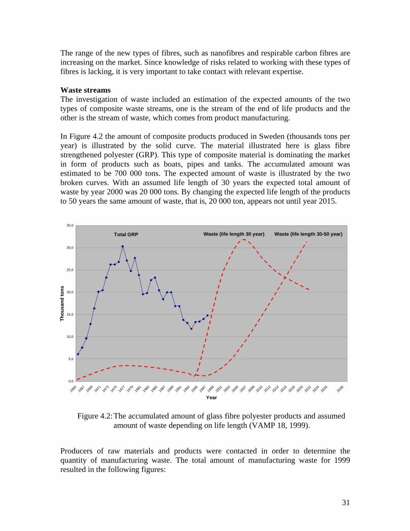
The range of the new types of fibres, such as nanofibres and respirable carbon fibres are increasing on the market. Since knowledge of risks related to working with these types of fibres is lacking, it is very important to take contact with relevant expertise. Waste streams The investigation of waste included an estimation of the expected amounts of the two types of composite waste streams, one is the stream of the end of life products and the other is the stream of waste, which comes from product manufacturing. In Figure 4.2 the amount of composite products produced in Sweden (thousands tons per year) is illustrated by the solid curve. The material illustrated here is glass fibre strengthened polyester (GRP). This type of composite material is dominating the market in form of products such as boats, pipes and tanks. The accumulated amount was estimated to be 700 000 tons. The expected amount of waste is illustrated by the two broken curves. With an assumed life length of 30 years the expected total amount of waste by year 2000 was 20 000 tons. By changing the expected life length of the products to 50 years the same amount of waste, that is, 20 000 ton, appears not until year 2015.
Figure 4.2: The accumulated amount of glass fibre polyester products and assumedamount of waste depending on life length (VAMP 18, 1999).
Producers of raw materials and products were contacted in order to determine the quantity of manufacturing waste. The total amount of manufacturing waste for 1999 resulted in the following figures:
31
- CFRP: 25-30 tons of which 2 tons are uncured - FRP- sandwich: 250 tons, PVC core: 850 tons - SMC: 400 tons - GMT: 200 tons Material recycling investigations A survey of the existing methods of material recycling was performed and the results were included in the inventory. As presented in chapter 3.2 a number of methods exists. Out of these methods, mechanical material recycling was selected as the most suitable method with respect to parameters such as waste stream, economy, feasibility of processing and application. Through earlier investigations the grinding process in a granulator with cutting knifes has been well documented for polymeric materials and FRP-composites (Ståhl et. al. 1997), (Reftman, 2002). A scheme for optimising the grinding process is developed, see Figure 4.3. The investigated materials, SMC, CFRP, GMT, PP/Flax are grouped according to three fragmentation types. These are defined from the left to the right on the x-axis as brittle – type I, between brittle and tough – type II, tough – type III. The fragmentation type is assessed through the “brittleness number” (Cs) determined by the toughness of the material. The y-axis describes the cutting edge load extending from low to high in form of the cutting resistance (Fs) which is coupled to the shear strength of the material.
3
Fragmentation type I Fragmentation type II Fragmentation type III
Tough fragmentationBrittle fragmentation
Low
cut
ting
edge
load
ing
Hig
h cu
tting
edg
e lo
adin
g
Cut
ting
resi
stan
ce F
s
PP/Flax
Figure 4.3: Diagram for characterising polymer materials and polymeric composites
for granulation through grinding (Reftman, 2002).
2
The cutting activity produced information, which is used as input for the cost and environmental analysis. This information was consumption of energy, see Table 4.1.
Table 4.1: Energy consumption for grinding of composite materials. After the grinding operation the material is separated from dust by a cyclone. The material can then be further sorted by passing through a sieve. This results in a higher quality material but increases the cost. To keep the costs down continuing tests of investigating manufacturing methods was made without sorting the material by sifting after grinding. For each material test specimens were manufactured for mechanical testing. The blending of recycled material and polymeric matrix was varied for evaluating appropriate amounts. The results of these tests were used to evaluate manufacturing method and to decide on which type of virgin material is suitable for replacement. In the cost and environmental analysis this information was used for comparing virgin and recycled material. Energy recovery investigations One important part of the inventory was to identify possible receivers of composite waste material for energy recovery. Two possibilities were identified (VAMP 18, 1999). The first one was incineration for generation of district heating. In Sweden about 100 power plants of this type exist. An interest in receiving new types of fuel was found for this type of plants. However, before using new materials as fuel, they must undergo thorough investigations according to demands on flue gas cleaning. The second possibility was treatment by waste incineration in plants equipped with flue gas cleaning, especially adapted to waste incineration. In Sweden a total of 23 plants, which use waste incineration for energy recovery exist. Out of these 20 plants were contacted during the inventory. This investigation revealed that composite materials as fuel were unknown to the majority of these plants, although it was found that three of the plants were receiving composite waste from clients regularly. To establish future waste handling of polymer composites by waste incineration, both verifying tests and spreading information were found necessary. Each material was examined by the following investigations in order to acquire valid information about incineration possibilities.
33
- analysis of elemental, elementary composition, heat value, ash content, etc. - analysis of dioxin, tetrachlordibenzodioxin (TCDD) - characterising incineration properties - large scale test at waste incineration plant The waste producer must be able to present information on exact content for the delivered material to the waste incinerator since they have demands on emissions. Consequently elemental and elementary compositions, heat values and ash content were investigated. Information on all tests and data concerning the included composite materials are presented in a technical report (Nyström, 2002). Generally the result indicates that it is possible to use composites as a fuel. The heat value varied from about 9 to 35 MJ/kg, see Figure 4.4, where the heat value as a function of ash content is illustrated. The heat value is dependent on type of composite and amount of fibre and additives. The low value for SMC material is explained by the high content of glass fibre and filler material.
0
5
10
15
20
25
30
35
40
0 10 20 30 40 50 60 70 80 90 100
Ash content [%]
Ther
mal
val
ue [M
J/kg
]
SMC
PP/FLAX
GMT
CFRP
UP/GLASSSANDWICH
FoThanwieqdiowacat20
34
Figure 4.4: Heat value as function of ash content for the investigated compositematerials.
r the analysis of dioxin high values were presented for the sandwich core material. is material contains high values of chlorine (Cl) which can be seen from the elemental alysis. For this type of material it is important to present chlorine content in contact th the incineration plant which then can make an assessment if the flue gas cleaning uipment can manage the increased chlorine and keep the allowed threshold value for xin. Each incineration plant has demand on emissions dependent on what type of ste they are allowed to treat. Worth mentioning here is that heavy metals acts as alyst for forming of dioxin, where copper (Cu) has the worst influence (Nyström, 02).
The characterisation of the composites as fuel included reactivity tests and comparison with known fuels as coal and bio fuel (Nyström, 2001). An interesting result of the tests revealed that the thermoplastic composite, PP/Flax, presented similarities to bio fuels and carbon fibre composite, CFRP, showed similarities to coal with respect to properties such as density, amount of ash and combustion rate. A parameter study pointed out the importance of temperature, oxygen level and mass in combustion rate. Especially for CFRP the oxygen level and the temperature were pointed out as important parameters, which need careful considerations in order to avoid unburned fibres and fly ash. A special problem for glass fibre containing composites was pointed out in regard to incineration plants containing a fluidised bed. With an incineration temperature higher than the melting point of glass (840-850°C) the glass will melt and stick together, de-fluidising the bed and deteriorate the incineration. The fluidised bed must then be restored due to decreased function For the large-scale test totally 13 tons of mixed composite waste were collected and incinerated during two days (Nyström, 2002a). Before incineration a fuel mixture was made by blending 10% by weight of composite waste with ordinary waste. Due to a filter breakdown the flue gas analysis was interrupted and therefore the test provided unreliable results. However, the importance of size reduction before incineration was identified by studying the ash. Here, pieces of unburned composite materials were found. According to the head of the plant no disturbances during the combustion were noticed, although the preparation before incineration, crushing, required more effort than the preparation of normal waste. For energy recovery, a complete incineration results in low emissions. To achieve this for composite materials the cutting/shredding and dilution activities are particularly important. For carbon fibre composites this is even more important in combination with high combustion temperature and with good supply of oxygen. Combination of material recycling and energy recovery A fluidised bed method combining energy recovery with material recycling was included in the project. In the thermal process the matrix material is transformed by to chemical components, which are used for producing energy and the carbon fibre is released and can be treated for material recycling, see chapter 3.2. This method has been investigated for both glass fibre and carbon fibre materials. In the project, manufacturing waste (carbon fibre prepreg) from manufacturing of aircraft structures was tested in a fluidised bed (Skrivfars & Nyström, 2001). Carbon fibre is an expensive material and through this method the fibre length is maintained to a larger extent compared to mechanical material recycling. Consequently a higher value can be achieved both in terms of strength in the new application and economy. Results of testing carbon fibres showed a decrease in mechanical properties compared to virgin, but by optimising the fluidised bed with respect to temperature and process the mechanical properties can be improved.
35
Techniques for cutting and crushing large structures Methods of cutting large structures were investigated by the case studies. Before the main process, incineration with energy recovery or mechanical material recycling by granulating, the size of material must be reduced to fit the actual process. From industrial participants in Vamp 18, two types of large end of life structures were delivered - boat hulls and tracked vehicle. The first method, which was investigated was cutting the structure into pieces of about 0.5 x 0.5 m by a hydraulic shear, see Figure 4.5. Through the examination it was concluded that this method works well with a few large end of life objects delivered irregularly. The waste collected for the large-scale incineration test included large sandwich structures of boat hulls. At the incineration plant these structures were treated by a specialised wheel loader. As mentioned in a former part of this chapter the head of the plant said that crushing was more demanding for this composite sandwich waste than for the waste normally received at the plant. This is explained by the toughness of the sandwich structure. Further size reduction of waste was necessary before treatment by mechanical material recycling. A hammer mill was used for this purpose to reduce the size of the material to about 0.1 x 0.1 m.
The process of cutting or shredding large structures has been studied in Japan for solving problems with abandoned leisure boats along the coast. An equipment was developed where boats of maximum length of 11 m are cut in pieces of 0.15 x 0.15 m in about half an hour time (Hedlund-Åström & Olsson, 1996). Working environment During the case studies the working environment was investigated with focus on generation of particles and noise. Especially for mechanical treatments as cutting, shredding and grinding these issues are very important. Results of the noise measurements during the grinding activity generally presented high values for all materials, that is above the threshold value of exposure during a day, which is 85 dB (AFS, 1992). Also pulsing noise, threshold values of 135 dB, was measured resulting in values over 110 dB (AFS, 1992). The measured total values for particles was normally below 0.1 mg/m3, which is very low since the hygienic threshold value for thermosets is 3 mg/m3 (AFS, 2000). However, personal protection against both particles and noise is recommended for work near the machinery. Other recommended measures are rebuilding the granulator for reduction of noise. A special treatment, necessary for mechanical material recycling of prepreg waste from manufacturing of CFRP-structures was investigated with respect to the working environment. On top of the uncured prepreg a thin protection film was mounted. This film was not compatible with the base material and therefore had to be removed. Since this handling was made by hand, generation of dust was measured (Christensson et al., 2001). As a result the workers were recommended to use gloves and respiration protection to avoid contact with particles contaminated with low molecular epoxy. During shredding large sandwich structures by a specialised wheel loader, generation of particles was measured (Christensson, 2001). The result of the measurement was half of the hygienic threshold value of thermoset materials.
37
38
5 Forming recommendations for material recycling and energy recovery
As mentioned in Chapter 2 several comparative investigations of alternatives to waste treatments with respect to environmental issues use the LCA method. There are also several tools for modelling waste treatment, especially for municipal waste. The aim of these tools is to plan for optimal solutions in terms of cost and environmental effects. In these tools life cycle assessment (LCA) is used for analysing environmental effects. Also in this study LCA is used, according to the ISO14040 standard (ISO14040, 1997), for comparing different types of waste treatments for the polymeric composite materials. 5.1 Goal and scope definition Goal and scope follow the ISO14040 standard. - Goal
To handle waste and discarded products from manufacturing and end of life products at low cost and low environmental impact. Furthermore recommendations will be prepared for Swedish waste producers’ choice of technique.
- Scope Material and product study and comparison of different waste treatment methods such as material recycling and energy recovery.
- Functional unit 1 kg of produced waste
- Studied product system CFRP, FRP-sandwich with PVC core, SMC, GMT and PP/Flax
- System boundaries Transports, core processes as crushing, grinding
- Inventory parameters CO2, SOx, NOx, for the data not included within the EPS 2000 Design System
- Types of effects and methodology for environmental assessment All types of effects, without restrictions. Environmental assessment according to EPS 2000 Design System
- Limitations Data valid for year 2000 in Sweden
- Critical review Bengt Steen
- Report Partial report and final report
39
5.2 Establishing of scenarios
Relevant scenarios are established in cooperation with the case study groups and with persons responsible for material recycling and energy recovery. The scenarios include all activities that are necessary for performing material recycling and energy recovery. Totally 22 scenarios are formed, which include all materials (see Appendix I). In Appendix II the costs and environmental effects for all scenarios are presented. For each scenario possible virgin materials and fuels are proposed to be replaced by the recycled and recovered composites. Common for all materials are scenarios for mechanical material recycling and for waste incineration with energy recovery. For all material recycling scenarios concerning production waste three different transport lengths are studied, 0, 200 and 400 km. The 0 km alternative means that the waste producer himself treats the waste and takes it back into production. For the scenarios describing energy recovery by production waste and end of life products the transport lengths studied are 200 km and 400 km.
A Carbon fibre reinforced polymeric composite (CFRP) - six scenarios A1 Mechanical material recycling uncured prepreg production waste for manufacturing
short fibre mat which replaces virgin short fibre mat manufactured with carbon fibre.
A2 Mechanical material recycling uncured prepreg production waste for manufacturing through extrusion and pultrusion, which replaces virgin short glass fibre or short carbon fibre.
A3 Mechanical material recycling cured prepreg production waste for manufacturing through extrusion and pultrusion, which replaces virgin short glass fibre or short carbon fibre.
A4 Energy recovery by waste incineration of uncured prepreg production waste, which replaces coal or building waste.
A5 Energy recovery by waste incineration of cured prepreg production waste, which replaces coal or building waste.
A6 Material recycling/energy recovery through fluidised bed of end of life product, for manufacturing through extrusion and pultrusion , which replaces virgin short glass fibre or short carbon fibre.
For CFRP the first five scenarios describe waste treatment of production waste. Scenario 1 is formed to investigate the possibility of utilising directly the uncured waste for making mat. In the manufacturing of CFRP structure the waste appears in both cured and uncured form, which is illustrated in scenario 2 and 3. At least one of the participating companies, which produce CFRP structures sends its waste for incineration. Since the uncured waste is classified as hazardous waste, it must be cured before transport. To determine the influence of the curing activity regarding costs and environmental effects, two alternatives for energy recovery are formed, scenarios 4 and 5. In the last scenario fluidised bed treatment of an end of life structure is studied.
40
B Fibre reinforced polymeric (FRP) sandwich with PVC core - five scenarios B1 Mechanical material recycling waste from production of core material, for
manufacturing through compressive operations, which replaces sawed virgin wood. B2 Mechanical material recycling waste from production of core material, for
manufacturing through extrusion, which replaces sawed virgin wood. B3 Energy recovery by waste incineration of waste from production of core material,
which replaces coal or building waste. B4 Mechanical material recycling of end of life products, for manufacturing through
compressive operations, which replaces urea based compression moulding compound.
B5 Energy recovery by waste incineration of end of life products, which replaces coal or building waste.
The first three scenarios are formed to illustrate material recycling and energy recovery by incineration of waste from manufacturing of the PVC- core material. For the treatment of a large end of life sandwich structures two alternatives are studied, which are material recycling and energy recovery, scenario 4 and 5. C Glass fibre thermoset composite, sheet moulding compound (SMC) - three
scenarios C1 Mechanical material recycling production waste, for manufacturing through
pultrusion, extrusion, compression moulding, which replaces virgin filler material or short glass fibre.
C2 Mechanical material recycling production waste, for manufacturing melamine or urea based compression moulding compound, which replaces virgin paper pulp.
C3 Energy recovery by incineration of production waste, which replaces coal or building waste.
In this study SMC production waste is studied in three scenarios, two alternative scenarios for material recycling and one scenario for energy recovery. D Glass fibre thermoplastic composite (GMT) - five scenarios D1 Mechanical material recycling of production waste, for manufacturing through
extrusion or liquid moulding, which replaces virgin polypropylene, PP. D2 Mechanical material recycling of production waste, for manufacturing through
compression moulding, which replaces virgin GMT. D3 Mechanical material recycling of production waste from decorative film, rubber
modified PP, for manufacturing through liquid moulding, which replaces virgin polyfenylenoxid, (PPO).
D4 Energy recovery by waste incineration of production waste, which replaces coal or building waste.
D5 Energy recovery by incineration for district heating, by manufacturing pellets of production waste, which replaces coal or building waste.
Three scenarios for recycling production waste are identified. Scenario 1 and 2 describe the process for GMT waste. When the GMT composite is used for interior parts in
41
vehicles, its surface is covered by a decorative film. From discarded components this film is dismantled and thereafter recycled. In scenario 3 this procedure is illustrated. Two scenarios, 4 and 5, illustrate two types of energy recovery. Scenario 4 describes ordinary waste incineration. Scenario 5 presents an attempt to use the GMT waste as fuel for district heating in form of pellets. E Flax fibre thermoplastic, PP/Flax, three scenarios E1 Mechanical material recycling of production waste, for manufacturing through
extrusion or compression moulding, which replaces virgin PP. E2 Energy recovery by waste incineration of production waste, which replaces coal or
building waste. E3 Energy recovery by incineration for district heating, by manufacturing pellets of
production waste, which replaces coal or building waste. These three scenarios resemble those formed for the thermoplastic GMT material. Also for PP/Flax, forming of pellets for energy recovery through district heating is analysed. 5.3 Inventory and valuation The inventory, collection of all data on environmental emissions and costs, for the activities in the scenarios will be described together with the valuation of the environmental impact for three selected scenarios. All collected data is presented in excel charts, see Appendix II. The cost is presented in Swedish currency, SEK, and the environmental impact is valued according to the EPS 2000 method in Environmental Load Unit, ELU. Inventory data, which have been calculated and not directly collected from the EPS 2000 database, project participants, and others are:
• cost of grinding, Table 1 and 2 • emissions from manufacturing of virgin carbon fibre, Table 3 • amount of fuel replaced by incineration of polymer composites, Table 4 • emissions from incineration of composite materials, Table 5 • landfill of ash from incineration, Table 6
Cost of grinding The cost of grinding is estimated by using information from a participant in the project – a company with experience in grinding of waste from manufacturing of GMT-products (Bengtsson, 2001). It is assumed that the machinery is used effectively and has a life length of 10 years. This includes the cost of personnel, machinery, disassembly and maintenance - and contractor’s profit is not included. In Table 5.1 these costs are presented, which are valid for the GMT material.
Table 5.1: Total costs per year for grinding of GMT manufacturing waste. A total of 400 tons of GMT material can be treated in one year. The estimated cost (per kg) of grinding of the composite materials is presented in Table 5.2. This estimation is made together with companies from the project having experience of the grinding technique, Rapid AB and Jomill AB.
Table 5.2: Costs per kg of grinding of fibre composites. The higher costs of grinding of SMC is explained by the higher glass and filler content, which results in more intense wear of the knives. The even higher cost of the carbon fibre can be decreased by a factor 3 by using knives manufactured in ceramic materials. Emissions from manufacturing of virgin carbon fibre The environmental impact of virgin carbon fibre manufacturing is based on information on energy consumption during the manufacturing process (Roos, 2001). A total of 400 MJ is consumed for producing 1 kg carbon fibre. In Table 5.3 the energy sources and the amount of energy are presented. Information about emissions and environmental impact is obtained from the EPS 2000 system database.
Table 5.3: Emissions and environmental impact of production of new carbon fibre.
43
Amount of replaced fuel from incineration of composite materials For valuation of energy recovery by using different composite materials the emissions are compared with replacements of two alternative fuels. The first alternative is coal, which is commonly used as extra fuel during the winter period at the incineration plants. The second alternative is building waste. This is an ordinary waste for incineration. The heat value of the building waste is assumed to be the same as for wood fuel since it contains large amounts of wood. Heat values for the composite materials were investigated through laboratory testing, see Chapter 4. The heat values for coal and building waste (wood fuel) were collected from EPS 2000 database. In Table 5.4 the heat values for the composite materials are correlated to the amount of replaced fuels. Material
Table 5.4: Heat values and amount of replaced fuel. Emissions from incineration Emissions of CO2, NOx and SOx are estimated by a method based on the elemental composition (Steen, 1999). As mentioned in chapter 4 the elemental composition was analysed for each composite material. From the EPS 2000 database the following information on impact of emissions are obtained. • 1 kg CO2 results in 0.108 ELU • 1 kg NOx results in 2.13 ELU • 1 kg SOx results in 3.27 ELU In Table 5.5 the elemental composition and calculated emissions are presented together with the total environmental impact for 1 kg of each material.
44
Material C [%]
CO2[kg]
N [%]
NOx[kg]
S [%]
SOx[kg]
ELU/kg
CFRP 92.7 3.39 1.3 0.0043 0.01 0.0002 0.37 Sandwich 45.8 1.679 0.2 0.0007 0.01 0.0002 0.18 PVC 55.1 2.019 5.1 0.0174 0.12 0.0015 0.26 SMC 24.2 0.887 0.1 0.0003 0.01 0.0002 0.0971 GMT 52.6 1.93 0.1 0.0003 0.03 0.0006 0.209 PP/Flax 78.1 2.86 0.2 0.0007 0.02 0.0004 0.3117 GMT-pellets 1.703 0.00213 0.0019 0.1909 PP/Flax-pellets 1.796 0.00217 0.0017 0.20117 Table 5.5: Calculated emissions from incineration of composite materials. The emissions and environmental impact of the pellets are based on elementary composition from wood pellets by 90% of value in combination with the value of 10% of GMT respectively PP/Flax. Landfill after incineration Also included in the environmental impact is the forming of ash, which is put in landfill sites. The ash content of the investigated materials is analysed through incineration tests at laboratory scale, see Chapter 4. The environmental impact of landfill is based on calculations of life stagnation on a specific surface, the woodland. The environmental impact of using woodland is 0.0455 ELU/m2 x year (Steen, 2002). The landfill is assumed to take place for a time period of 50 years causing a pile, 10 m high. With a density of 1000 kg/m3 the environmental impact then becomes 2.275E-4 ELU/kg for landfill. As stated in the goal and scope definition the amount of material from the beginning is 1 kg. In Table 5.6 the total environmental impact of landfill due to ash content for each studied material is presented. Material
Table 5.6: Environmental impact of landfill of ash.
45
Valuation of three scenarios Three scenarios with collected and calculated data are presented more extensively. The remaining 19 scenarios, presented in Appendix I, mainly resemble these three examples with small variations. The three selected scenarios are:
• scenario A2, mechanical material recycling of CFRP prepreg production waste
• scenario B5, energy recovery through waste incineration of an end of life product in FRP-sandwich
• scenario E3, energy recovery by incineration for district heating through forming of pellets
A2 Scenario and inventory data for mechanical material recycling of CFRP prepreg waste The following scenario, Figure 5.1, illustrates the activities, which are involved in recycling of production waste consisting of carbon epoxy prepreg. The produced waste described here is in uncured condition. On both sides of the prepreg a protection film is attached. This plastic film has to be dismantled before curing since it is not compatible with the prepreg. During the removal, which is done manually, the working environment in respect to dust generation is studied, see Chapter 4. Since the continued treatment of the protection film is not included in the scenario, the dismantling activity increases cost but has no effect on the environment. The (excel) chart attached to this scenario is presented in Table 5.7. The next activity, which is curing, affects both costs and environment through costs of staff and consumption of energy. Information on cost and energy consumption for the dismantling and curing of prepreg activities is obtained from Saab AB in Linköping.
Dismantling of protection
film
Curing
Compression
Working environment
CFRP waste
46
Grinding
Working environment
Replacement of short glass or carbon fibres
Transport
Figure 5.1: Scenario for recycling of CFRP prepreg waste. The next two activities, compression and transport of the waste (400 km), affects both cost and environment. By reducing the waste volume through compression; the effectiveness of transportation increases. Polytech AB in Ljungby (one of the participants in the project) provided information on energy consumption and cost of the compression activity.
1 kg CFRP prepreg waste CO2 NOx SOx Cost kg kg kg ELU SEK Activity Dismantling of protection film 16.1 Curing 2.44 0.0055 0.0127 0.71 14.75 Compression 0.005 0.00001 0.00003 0.0015 0.41 Transport 400 km 0.034 0.0002 0.00005 0.0099 0.42 Grinding 0.036 0.00008 0.00019 0.0105 30 Recycled material 2.515 0.00579 0.01297 0.7319 61.68 Replaces virgin short glass fibre 2.07 0.005 0.013 0.329 30 Recycled/glassfibre quotient 2.22 2.06 Recycled-glassfibre difference 0.4 31.68 Replaces virgin short carbon fibre 66.6 0.0963 0.17 19.8 185 Recycled/carbon fibre quotient 0.04 0.33 Recycled-carbon fibre difference -19.07 -123.3
Table 5.7: Inventory data and results for recycling of CFRP prepreg waste.
47
Information on environmental effects and costs of the transport was collected from the EPS 2000 database and Schenker BTL homesite respectively. Data on emissions from all processes where electrical energy is consumed are obtained from the EPS 2000 database. After transport the waste is ground. Energy consumption during grinding is measured in the experimental studies of grinding, see Chapter 4, Table 4.1. For costs assessment of the grinding process information was obtained from two companies, Rapid AB and Jomill AB (which both participated in the project). This information includes costs of the granulator, maintenance, personnel and preparation, see Table 5.1 and Table 5.2. The grinding process was also studied from the working environmental point of view considering noise and dust generation. After collecting all data for the scenarios these are summarised and related to the corresponding data on the virgin material (which is suggested that it should replace). These are introduced in the last part of the charts, Table 5.7. In this case the suggested replaced virgin materials are short glass fibres or short carbon fibres. Costs of these materials are obtained from project participants. Data on emissions from production of glass fibre are taken from the EPS 2000 database. Data on emissions from production of virgin carbon is provided by fibre a supplier - see Table 5.3. To compare the recycled material with the virgin replacement a quotient and a difference are formed for both cost and environmental effects. For a quotient less than one and a negative difference, the environmental impact and the cost of the recycled material are less than the corresponding figures for the virgin material. The comparison with the first alternative, that is virgin short glass fibre, resulted in a quotient larger than one for both cost and environmental impact. This means that the recycled material will increase the environmental impact and costs if it replaces the glass fibre. The second alternative of replacement is virgin short carbon fibres, resulted in negative differences and quotients below one for both costs and environmental load. By replacing virgin carbon fibres with recycled material the environmental impact is reduced about 25 times and the costs decreased about 3 times. Even larger reduction is achieved by another replacement, suggested for recycled uncured carbon fibres, which is illustrated in scenario A1, Appendix 1. Here mats made of recycled carbon fibre replaces mats from virgin fibres, resulting in a cost reduction of about 14 times and a reduction for the environmental impact for about 100 times. B5 Scenario and inventory data for energy recovery by waste incineration of sandwich structure The scenario in Figure 5.2 describes the activities involved in energy recovery by waste incineration of an end of life structure in FRP-sandwich. For a used product, irrespective of material recycling or energy recovery, the first three activities, disassembly, transport and shredding are the same. In some cases (for material recycling) it is also necessary to cut the structure before shredding. This is dependent on
48
structure’s size. Within this project both cutting and shredding are investigated for large sandwich structures, which are described in Chapter 4. The cutting of a large sandwich boat hull in pieces of 0.5 m x 0.5 m is carried out within 15 minutes. In the shredding activity generated dust is measured, see Chapter 4. Higher costs are generated in this first part of the scenario, especially for disassembly, since the intensity of manual work was high. Information on costs of disassembly is obtained from two participating companies, Nimbus AB and Hägglunds AB. The chart of data on costs and environmental effects related to the sandwich scenario is presented in Table 5.8.
Disassembly
Transport
Shredding
Incineration
Working environment
Replacement of coal or
building waste
Landfill
Sandwichstructure
Figure 5.2: Scenario for energy recovery by incineration of sandwich product
49
In this scenario the transport (400 km) takes place directly after disassembly. This is in the actual order of how the investigation in the case study is performed. After shredding, the material is incinerated at a plant for waste incineration with heat or energy production. In the cost, 1 SEK/kg (see Table 5.8), the costs of the required activities, that is, the costs of shredding, mixing, incineration and landfill of ash are included. Information on this cost is obtained from a plant for waste incineration, namely, Norsaverket in Köping. The amounts of emissions from incineration of the polymer composites are calculated from the elementary composition, which is investigated in the energy recovery project, see Table 5.5.
1 kg sandwich waste CO2 NOx SOx Cost kg kg kg ELU SEK Activity Disassembly 20 Transport 400 km 0.72 0.0063 0.0002 1.2363 16.7 Shredding 0.03 0.0002 0.0099 Mixing Incineration 1.68 0.0007 0.0002 0.18 1 Landfill of ash 0.0001 Total 2.43 0.0072 0.0004 1.4263 37.7 Replaces virgin coal 2.54 0.0046 0.0385 0.4512 Total/coal quotient 3.16 Total-coal difference 0.98 Replaces building waste 0.0113 0.0019 0 0.0072 Total/building waste quotient 198.1 Total-building waste difference 1.42
Table 5.8: Inventory data and results for energy recovery by using sandwich structure.
Depending on the type of composite, fibre, and filler content, a certain amount of ash is formed. Also this characteristic is investigated in the experimental tests for obtaining incineration data on all materials, see Chapter 4. The ash is put in a landfill site. The environmental impact of landfill is calculated from using woodland, which is valued in the EPS 2000 program, see Table 5.6. Finally a comparison is made with replacements of two fuels, which are used in waste incineration plants, namely, coal and building waste. Building waste mainly includes wooden material. The amount of replaced coal or building waste is related to the heat value of the incinerated composite materials, see Table 5.4. Emission data for these replacements are collected from the EPS 2000 data base. The resulting quotient for the two comparisons turned out to be over one, meaning that energy recovery by incineration of sandwich material generates more environmental impact than both incineration of coal and building waste. Concerning the costs of the waste producers point of view, sending the waste for incineration, will always result in a cost.
50
E3 Scenario and inventory data for energy recovery by incineration of pellets produced from PP/Flax manufacturing waste Figure 5.3 presents the scenario for energy recovery by incineration for district heating.
Compression of pellets
Transport
Landfill
Replacement of coal
Incineration
Compression
Mixing with wood
Grinding
Transport
PP/Flax waste
Working environment
Figure 5.3: Scenario for forming of pellets for district heating.
51
The activities in this scenario describe the process of forming pellets, which then are incinerated. The reason for this alternative is to investigate a possibility for the waste producer to receive payment for a waste with a high heat value. In this scenario the first Before forming of pellets the waste is ground. The cost and environmental impact of grinding of this PP/Flax composite were analysed in the same manner as the carbon fibre composite in scenario A2, see Table 4.1 and 5.2. A mixture containing 10 % PP/Flax waste and 90 % wood by weight is then produced. The rather high environmental impact of mixing in Table 5.9 (from EPS 2000 database) originates from the production of 9 kg wooden chips. Information on costs of wooden chips is obtained from ASSI Domän. The compression operation results in the formation of pellets, this increases environmental impact and costs through energy consumption. Information on cost is obtained from Bioenergi in Luleå and information on energy consumption is obtained from JTI, Swedish Institute of Agricultural and Environmental Engineering. The second transport in this scenario is also assumed to be 200 km in length. Compared with the former scenario (energy recovery by incineration of a sandwich structure), where the waste producer had to pay for the treatment, the forming of pellets is assumed to result in an income. The sign of the cost in Table 5.9 is therefore negative and it is valid for 10 kg pellets. Information on cost of pellets is delivered by ETC, Energy Technology Centre in Piteå. Similar to the formerly presented sandwich scenario amounts of emissions from incineration of pellets are calculated from the elementary composition, see Table 5.5. The comparison of the total result with regard to the environmental impact is made with the replacement of coal. No cost comparison is made since the investigation considers waste treatment from the waste producers’ perspective. The comparison of the incineration of pellets with using coal reveals that by incineration of pellets the environmental impact is decreased. The pellets contain 90% wood, which is favourable to the environment since wood is a renewable material.
1 kg PP/Flax waste CO2 NOx SOx Cost kg kg kg ELU SEK Activity Compression 0.005 0.00001 0.00003 0.0015 0.41 Transport 200 km 0.017 0.0001 0.00002 0.0049 0.28 Grinding 0.0228 0.0001 0.0001 0.0067 1 Mixing with wood 1.62 0.0036 0.009 0.2862 2.25 Compression of pellets 0.1857 0.0004 0.001 0.054 4 Transport 200 km 0.17 0.001 0.0002 0.049 2.8 Incineration 17.96 0.0217 0.017 2.0117 -9 Landfill of ash 0.000013 Total 19.9805 0.0269 0.0272 2.414 1.74 Replaces virgin coal 26.07 0.0474 0.395 4.6294 Total/coal quotient 0.52 Total-coal difference -2.22
Table 5.9: Inventory data and results for energy recovery by incineration PP/Flax waste.
52
Comparing manufacturing of pellets for district heating (scenario E3 Figure 5.3) with ordinary waste incineration (scenario E2 in Appendix I and II) the total cost of district heating by using pellets becomes higher despite the assumption of incomes from selling the pellets. 5.4 Recommendations From the results of the cost and environmental analysis recommendations are formed for each material. Though, three general comments are pointed out which are valid for all investigated materials. For both mechanical material recycling and energy recover by waste incineration of manufacturing waste the transport is regarded as effective concerning both cost and environmental effects. For end of life structures the transport is analysed as a volume transport which is not effective. When material recycling is recommended an alternative that results in the lowest cost and environmental impact is when the waste producer himself processes the manufacturing waste for reuse, because in this case the transport length becomes 0 km. For energy recovery by waste incineration one of the replaced fuels is building waste. This replacement results in a large increase of environmental impact for all scenarios and it is not recommended. Carbon fibre composite, CFRP - Material recycling through both mechanical material recycling and fluidised bed of
CFRP manufacturing waste and end of life product is recommended with replacement of virgin carbon fibre since both cost and environmental impact are decreased.
- Mechanical material recycling of CFRP manufacturing waste is not recommended with replacement of virgin glass fibre since this results in an increase of environmental impact and no economic gain.
- Energy recovery by incineration of already cured CFRP manufacturing waste is recommended with replacement of coal since the environmental impact is decreased.
- When comparing energy recovery by incineration of uncured and cured CFRP waste, the uncured waste results in less environmental impact and lower cost, although a special license is needed for combustion of uncured material.
- Incineration of uncured manufacturing waste, which must be cured, results in higher environmental impact compared to incineration of coal.
PVC-core and FRP-sandwich - Mechanical material recycling of PVC-core waste products is not recommended with
replacement of wood since both costs and environmental impact increases.
53
- Energy recovery by incineration of PVC-core waste is recommended, which results in low cost and decreased environmental impact (when coal is replaced).
- Material recycling of end of life sandwich structure is recommended with replacement of fenol or urea based compression pulp, which results in the low environmental impact, if the transport length is less than 400 km.
- Energy recovery by incineration of end of life sandwich structure is not recommended, since the environmental impact is increased compared to incineration of coal.
Glass fibre thermoset, SMC - Material recycling of SMC is recommended when virgin short glass fibre is replaced
which results in gain in cost and decrease of environmental impact. - Replacing virgin filler also results in decreased environmental impact but no
economical gain. - Energy recovery by incineration of SMC can be considered when coal is replaced. Glass fibre thermoplastic, GMT - Material recycling of GMT results in both cost gain and decreased environmental
impact. - For maximum cost gain replacement of virgin GMT is recommended. - For maximum decrease in environmental impact replacement of virgin
polypropylene, PP is recommended. - Energy recovery by waste incineration of GMT is recommended with replacement of
coal. - Energy recovery by producing of pellets results in higher cost than waste incineration. Flax fibre thermoplastic, PP/Flax - Material recycling of PP/Flax is recommended with replacement of virgin
polypropylene, PP. - Energy recovery by waste incineration of PP/Flax is recommended with replacement
of coal. - Energy recovery by producing of pellets results in higher cost than waste incineration. 5.5 Sources of error The choice of replaced virgin materials and fuels has large influence on the result. This is clearly illustrated in the analysis since several alternative replacements are studied for both material recycling and energy recovery. For material recycling, 1 kg recycled material is assumed to replace 1 kg of virgin material. This is not fully correct since material properties of the recycled material are affected by mechanical treatment and ageing. In a study of recycling and recovery of plastic parts in end of life vehicles (Jenseit et al., 2003) this circumstance is studied for a bumper made from polypropylene, PP. Here, the relation between the quantity of virgin material, which can be substituted by recycled material (and which has the same
54
characteristics), is designated as the substitution factor. In the bumper example the effects of environmental impact and cost are compared with two substitutions factors 0.95 and 1. The result clearly shows an increase of both environmental impact and cost for the lower substitution factor, were 0.95 kg virgin material is replaced by 1 kg recycled material. In another study a model for environmental valuation of recycled material has been developed for end of life scenarios in LCA (Strömberg et al., 2002). This model is based on a combination of the economical value of products on the second hand market and the material quality of the recycled material. Since no second-hand market exists yet for composite materials this model can not be used. Prior to this model recycling credits based on the quality decrease were developed. There can also be a problem to even find a relevant material to compare the recycled material with. This is true for recycling of the sandwich core material in scenarios B1 and B2. The recycled material in these scenarios is compared to sawed wood. The recycled core material has excellent water absorption properties, which means lower water absorption than the sawed wood. This property was investigated in a Nordic project working especially on recycling of FRP-sandwich materials (Hedlund-Åström & Olsson, 1997). The treatment of 1 kg waste is assumed to produce 1 kg fuel or 1 kg recycled material. An effect, which is not considered, is material loss by forming of particles through cutting, crushing, and grinding. The scenarios for material recycling, B4, and for energy recovery, B5, for sandwich structures (figure 2) start with the disassembly activity. The complete cost of this activity is put on the sandwich material, this is not correct since the structure contains metallic parts and electronic device, which should bear part of the cost. As mentioned in the calculation of the cost of grinding the profit for the contractor was not included. For the scenarios with a transport length of zero km, where the waste producer recycles the material himself, this cost is correct for the waste producer. If the waste producer chooses to send the waste to a contractor and then take it back, the cost would be higher than illustrated in the tables due to contractor expenses. Another alternative which is not realistic since no market for recycled material exists is the possibility of receiving payment by selling the waste to a contractor.
55
56
6 A model for end of life treatment of polymer composites
Preparing for the future end of life treatment is important for product manufacturers, due to the increased environmental demands (based on legislation) and common awareness. This is especially important for products containing composite materials since these materials commonly are thought not to be recyclable. Fibre composite is a group of materials with heterogeneous contents as presented in Chapter 3. There are several types of fibres and polymeric matrix; there are also several different additives. An even more complex material mixture is obtained in different forms for a composite sandwich structure also including core material. Knowledge of exact contents is especially important for material recycling for producing high quality materials. Exact knowledge of the contents increases also the possibility of combining different materials for increasing waste streams. Much information for the treatment of composite waste was gained as empirical knowledge through the VAMP 18 project and all of this information is not visible in the recommendations based on the environmental and economical analysis. However, the important conclusions of the VAMP 18 project are: • Procedure for grinding composites depends on the type of composite • Important to consider for energy recovery are:
- high glass content - carbon fibre composites - PVC-core
• For disposal of large structures the transport can be more effective In order to obtain a good quality of the recycled material the grinding process is important. Depending on the type of composite material the grinding process can be optimised, see Chapter 4. During waste incineration (especially in a fluidised bed) problems with large volumes of glass fibre composite waste can occur. The glass will melt and sinter the sand in the bed, which then has to be restored. For energy recovery by incineration of carbon fibre composites, especially prepreg material with high fibre content, it is important to decrease the size of the waste in order to achieve an effective incineration. As mentioned in Chapter 4 the incineration temperature and oxygen level are also of importance. In the scenarios for material recycling and energy recovery by incineration of the sandwich structure (D4 and D5 in appendix 1), the environmental impact and the cost of the transport are higher than in all other scenarios, because the analysis considers transport of a large object. In the other scenarios (for manufacturing waste) the transport
57
is regarded as effective. For the sandwich structure the transport could be made effective by changing the order of the transport and cutting activities. This would then affect the final result (the recommendations) since both environmental effects and costs would decrease. But this was not considered in the analysis (Chapter 5). An alternative discussed (Reinholdsson, 2005) is to transport the cutting equipment to the actual place for the end of life structure and cut it there. Working environment and risks of accidents for the surrounding ordinary activities and personnel then has to be considered, since cutting of large structures generates both noise and dust. As mentioned in chapter 4 this problem has been studied in Japan resulting in mobile devices for treatment of end of life ships and automatic cutting of pleasure boats up to a specific length. Based on available research results, as well as on reported experience from full scale industrial applications, see Chapter 3.2, for handling of fibre composite waste, a generic model has been developed to facilitate planning of the future fibre composite waste handling. The model provides useful information for waste producers as material and product manufacturers and waste receivers. A number of alternatives to treatment of fibre composite waste exist resulting in material and/or energy recovery. These are presented in Chapter 3.2 and listed below together with the results of the processes, which appear in parentheses. • Reuse (new material) • Mechanical material recycling (material, a mixture of matrix and fibre) • Pyrolysis (raw material from the matrix and material from the fibre) • Fluidised bed (energy from the matrix and material from the fibre) • Cement manufacturing (energy from the matrix and material from the fibre) • Hydrolysis (recovery of expanded foam in sandwich structure) • Incineration (energy in form of heat or electricity) • Landfill As illustrated in Figure 6.1, the basic question here is, what influences the choice of waste treatment?
Figure 6.1: Options for end of life treatment of composite material.
compositewaste
material
material/energy
energy
landfill
?compositewaste
material
material/energy
energy
landfill
?
58
6.1 Influencing factors There are several factors that will influence the choice of treatment of waste composite materials. A distinction between internal and external factors is made, which has been discussed and presented in two papers (Hedlund-Åström et al., 2004), (Hedlund-Åström & Luttropp, 2004). An illustration of these influencing factors is presented in Figure 6.2. The internal factors are related directly to the waste and to the processes of treating the waste. They are divided into two groups, waste properties and process properties. Other factors, which influence indirectly the treatment, are external factors. They are divided into two groups, legislation and market.
Internal factors
Process properties
Waste properties
Market Legislation
External factors
Influencing factors Figure 6.2: Division of influencing factors in end of life treatment of composite waste. The proposed model in this thesis is based on the internal factors. However, the external factors - as regulations of working environment and of external environment - must be followed. A complete distinction between internal and external is not possible since they in some ways are interrelated. An example on this is the process drying of the waste, which is not included. The content of moisture is dependent of how the waste is stored and storing is ascribed to the external market factor. Type of waste, waste producer and receiver The following types of composite waste exist: • Manufacturing waste
- Constituent material production - Product manufacturing
59
- Discarded new products • Waste from end of life products • Waste from maintenance and accidents
Manufacturing waste comes from constituent material production, product manufacturing or discarded new products. Constituent material production includes fibre, matrix and core production as well as pre-impregnated reinforcement in form of prepreg and moulding compounds. Waste from end of life products is products or part of products, which do not fulfil their original intended function. Waste is also produced from maintenance of products and from products, which are involved in accidents. This type of waste is not included in the proposed model. Different types of producers, which have varying knowledge of the waste properties, see Table 6.1, produces the waste. Material manufacturers that produce constituent material as fibre and polymeric matrix material have a high level of knowledge of their material and produced waste. Product manufacturers obtain very often their materials from suppliers, and many products contain several types of materials. For this reason product manufacturers’ level of knowledge of exact properties of materials, which constitute a complete product, is low. This assumption is based on the results of a master’s thesis in which information from car manufacturing companies are used to determine the amount of composite materials in these companies’ products (Bumbar & Tegbring, 2004). The lowest level of knowledge of material properties is often found in treatment of end of life products, because many products are scrapped either after a long life length or in other countries, than where the product has been manufactured and primary used. Waste producer/reciever Type of waste Level of Knowledge Material manufacturer Manufacturing High Product manufacturer Manufacturing and products Varying Product user End of life Low Contractor All types Low Table 6.1: Waste producer and knowledge of the waste. The varying levels of knowledge call for preparing new products with waste handling plans to facilitate waste disposal in the future. This is especially important for products, which are designed to have long life. There are three kinds of waste receivers: • Material manufacturers • Product manufacturers • Contractors The waste receivers need knowledge of processes and related properties in order to handle the waste. In manufacturing the waste receiver can be the same person or organisation that produces the waste. In this case the material manufacturer or the product manufacturer recycles the waste and brings it back into the production. On the
60
other hand the waste producer can choose to deliver the manufacturing waste to a contractor for treatment, which then is dependent on the market situation for recycled material. 6.2 A model for waste treatment Based on the internal factors a model is developed to assess possible methods of recycling and (material/energy) recovery. Especially the waste properties are important since they identify the waste and thereby control the future waste treatment. The model presented in Figure 6.3 starts with the composite waste. Dependent on the disposal options chosen a number of processes are used to obtain material, energy, material/energy or to decide on landfill. These processes are identified by their process properties. The treatment conditions are set by the required processes through their process properties, which are coupled to information about the waste, the waste properties. For example, process properties, which we need to know in order to accomplish a cutting process, are capacity, size of end of life product, cutting edge material/hardness etc. These properties need to be correlated to the waste properties including information on type of material, size and metallic inserts etc.
compositewaste
CONDITIONS
processes
material
energy
material/energy
landfill
compositewaste
CONDITIONS
processes
material
energy
material/energy
landfill
Figure 6.3: A model for treatment of composite waste.
61
The relevant waste properties of composite waste are presented in the list below. Each property is presented by its abbreviation (which consists of three or four letters) and a unit of measurement. These abbreviations will be used for selection of waste properties and for illustrating the model for different waste treatments. • Constituent materials, type of fibre FIB, matrix MTX, filler FIL, core CORE in
volume [m3] and/or weight [kg]. • Hazardous substances and performance, HAZ, type, and amount in [kg] and position. • Analysis of chemical content, CHEM, in % of weight. • CHEM+, characteristic - specific to landfill • Metallic equipment and inserts, MET, type of metal and position. • Size, SZE, described by volume [m3] and/or weight [kg]. In contact with a waste receiver, a contractor, information on the total delivered amount of waste is acquired. As mentioned earlier composite waste treatment starts with composite waste. This means that the disassembly process of products, which contain several materials, is not included in the model. End of life structures are often contaminated with filth, this is assumed being cleaned when necessary. The included treatment processes, their process properties, and the required waste properties are presented below. Dismantling – this process is used for several treatments in order to prepare the materials for further processing and involves destroying separation. In treatment of end of life structures, especially different types of sandwich structures, large metallic inserts and electrical cables have to be dismantled before shredding or grinding to avoid damage on the equipment. The positions of the metallic inserts have to be known, MET. End of life products are often surface treated by paint. The content of the paint must be known since it can contain hazardous elements, HAZ. In order to proceed with mechanical material recycling the paint must be removed, for example by sand blasting. Also components containing hazardous elements, HAZ, can be removed through dismantled Another important issue is the risk of forming of hazardous gases when material is heated through mechanical processing as cutting, milling or drilling, HAZ. In dismantling of metallic inserts and cables by mechanical work the knowledge of fibre type, FIB, is of value since work up of some materials can cause large tool wear. Process properties for dismantling: manual work with cutting tool, cutting edge material, personal protection Waste properties required for dismantling: FIB, HAZ, MET
62
Cutting – this process is mainly ascribed to large structures meaning an equipment as a shear scissor, described in Chapter 4, can be used. With this equipment the structure is cut down to smaller pieces of about 1 x 1 m2, SZE. The purpose of this is to obtain a suitable size for the following process. Knowledge of original size and final size is needed. During this process also metallic inserts, hazardous content in concentrated form and other undesirable items can be removed, MET, HAZ. Also information on hazardous content for the same reason as for dismantling is needed. The type of fibre of the composite material FIB, is important for planning the cutting operation, see the previous process, dismantling. Process properties for cutting: cutting edge material, size of waste and final size, personal protection Waste properties required for cutting: FIB, HAZ, MET, SZE Shredding – after cutting, or for small sized waste, shredding is used for further reduction of size. Demands are set on inlet size, SZE, which is dependent on machinery used for shredding, about 1 x 1 m2. As for cutting, information on type of fibre, FIB, are important. Shredding can be made with several types of devices, for example a hammer mill. Large metallic parts should not be present, MET. To assess risks concerning the working environment knowledge on hazardous content is important, HAZ. Process properties for shredding: cutting edge material, inlet size, personal protection Waste properties required for shredding: FIB, HAZ, MET, SZE Grinding – the material is further processed for reducing size from maximum 0.5 x 0.5 m2 (dependent on granulator) to sizes from several millimetres down to particle size. The constituent materials must be known in order to adjust the granulator or mill, FIB, MTX, FIL, CORE, according to the scheme presented in Figure 4.3. Metallic parts should not be present, MET as well as hazardous elements can cause environmental effects in the following product life cycle, HAZ. Depending on type of granulator the inlet size varies, SZE. To assess risks concerning the working environment knowledge on hazardous content is important, HAZ. Process properties for shredding: granulator adjustments, cutting edge material, no large metallic parts, inlet size, personal protection Waste properties required for grinding: FIB, MTX, FIL, CORE, HAZ, MET, SZE Fluidised bed – this process is a heat treatment process by which the matrix is used for energy recovery and the fibre is released and transported by fluidising air, see Chapter 3.2. The temperature of the treatment depends on the type of fibre, FIB, and the chemical composition, CHEM, should be known to assess the contents of the flue gases. Demands on size of the waste, SZE, are dependent on the size of the equipment.
63
Process properties for fluidised bed: temperature 450-550°C, inlet size, flue gas cleaning Waste properties required for fluidised bed: FIB, CHEM, SZE Pyrolysis – this is also a heat treatment process, which is accomplished by the absence of oxygen, see Chapter 3.2, where the matrix is transformed to chemical components releasing the fibres. This process requires the same waste properties as the fluidised bed process. Process properties for pyrolysis: temperature 400-500°C, inlet size, flue gas cleaning Waste properties required for pyrolysis: FIB, CHEM, SZE Cement manufacturing – this is another heat treatment process, see Chapter 3.2, requiring information on chemical content, CHEM. Metallic elements must be dismantled since they are not accepted in the process, MET. There are specific demands for minimising the size, SZE, in order to increase the reactive surface of the material and thereby increase the effectiveness of the process. Process properties for cement manufacturing: temperature up to 2000°C, no metals and PVC, size demands (90% > 0.01 m, 100% < 0.05 x 0.05 x 0.02 m), flue gas cleaning Waste properties required for cement manufacturing: CHEM, MET, SZE Hydrolysis – this process is considered especially for sandwich structures containing expanded PVC as core material, see Chapter 3.2. Demand on size is due to increase the effectiveness of the chemical process, SZE. Also for this process the chemical content, CHEM, should be known for assessing the waste since this process takes place at elevated temperature. Process properties for hydrolysis: temperature 260°C, size about 0.02 x 0.02 m, flue gas cleaning Waste properties required for hydrolysis: CHEM, SZE Incineration – by waste incineration the energy from burning the composites is transformed to heat or electricity. For delivery of waste, the waste receiver is obliged to collect information on the amount of waste. In Sweden, the following regulations are in force (SFS, 2002:1060), (SFS, 2001:1063). No specific demands on declaration of content are found in waste incineration regulations, except for waste classified as hazardous (SFS, 2002:1060), (NFS, 2002:28). According to The Swedish Association of Waste Management (Hagelin, 2005) each waste incineration plant has regulations, which depends on type of permitted waste and on specific requirements concerning emissions. Then the plant is obliged to control the received waste to fulfil their requirements. Within the VAMP 18 project five waste incineration plants were contacted for incineration of composite waste (Nyström, 2002) The information asked for by varied from heat value and ash content to full information of elementary composition in together with heat value and ash content. What is included in the abbreviation CHEM is determined by each waste incineration plant. In regard to large products their size must be reduced to enable an effective incineration, SZE.
64
Process properties for waste incineration: size demands, flue gas cleaning dependent on which types of waste incineration plant has permission to handle Waste properties required for incineration: CHEM, SZE Landfill – for landfill, the waste producer is asked to present basic characteristics of the waste, these are included in the following Swedish regulations (NFS, 2004:10), (NFS, 2004:4), included are size, composition, and leakage properties, CHEM+. Glass fibre not including organic bonding is included on a list for material which can be received for “inert” landfill without testing according to the above given characteristics (NFS, 2004:10). Process properties for landfill: regulated in (NFS, 2004:10) and (NFS, 2004:4) Waste properties required for landfill: CHEM+ 6.3 External factors The external factors cannot to the same extent as the internal properties be influenced by the waste producer. However, the external factors can be influenced by creating opinion with respect to regulations, by creating demand for specific treatment methods, and by communicating with authorities. In most cases, the waste producers must act according to the present situation on the market. An exception is mechanical material recycling of manufacturing waste, here, the waste producer has the possibility to act and to recycle the waste, and use it in his own production. The treatment of end of life products is more complex due to the sometimes considerable time span between manufacturing and disposal, as well as that different actors usually are involved. The external factors, as mentioned earlier, are market and regulations. Market To establish a market, several factors are of importance. These are: • Amount of waste • Infrastructure (transport, storage etc.) • Costs • Applications To guarantee a high quality and access to material a reasonably stable and sufficient flow of material is important. This is also important for the economy of the activity. In Sweden the total amount of composite waste is estimated to approximately 20 000 ton/year, see Chapter 4 (VAMP 18, 1999). The waste volumes generated of composite materials in Western Europe is presented in Figure 6.4 (SMC, 2005). In Figure 6.4 waste from production and end of life products of different types of polymer composites is included.
65
Figure 6.4: Generation of FRP waste in Western Europe (SMC, 2005). With regard to infrastructure, transport and handling of the waste are important factors for decreasing costs. As mentioned at the beginning of this chapter it is recommended to carry out size reduction, cutting and shredding before transport. This, results in an effective transport both economically and environmentally. The importance of effective waste collecting systems is pointed out in a study investigating the environmental and economical performance of mobile phones (Clift, 1998). Here, phones manufactured from recovered parts and recycled materials are compared to phones manufactured from virgin material. For both reused and recycled alternatives the environmental impact becomes lower, but the cost is higher than for the phones produced from virgin material. This is explained by the high costs of collecting and dismantling. Another example is the ERCOM project, which is mentioned earlier in chapter 3. Here, the collection of waste was made with a mobile shredder and this resulted in an effective transport. However, this company was forced to quit its activity as a result of a non-existing market. Consequently the cost of producing recycled material became higher than the cost of virgin material, which it was intended to replace. Ideas of applying recycled materials are not lacking but in order to make them cost effective they must compete with the costs of virgin materials. This fact is also mentioned in the study of mobile phones (Clift, 1998). It says “the undervaluing of primary resource industries makes reuse and recycling uneconomic in spite of the associated environmental benefits”. For producing the raw material for one phone, solid waste in the order of 200 times the weight of the phone is produced.
66
However, it is well known that recycling including disassembly and dismantling are processes, which are more labour intense than manufacturing from virgin materials. Also the working environment conditions are worse for the recycling processes. These circumstances strongly contribute to the higher costs for recycled material. Regulations Except for waste regulations related to the external environment also the regulations considering working environment are included. Problems regarding working environment can come up in many of the presented waste treatment processes. Especially the processes where material is mechanically processing, that is dismantling cutting, shredding and grinding. During these processes exposure to the following can occur: particles from matrix, fibre, core sharp fibres smoke, gas noise
Also risks for accidents when handling the tools can occur. In Swedish working environment regulations threshold values are set for exposure of specific substances, particles, fibres and noise (AFS, 2005:17), (AFS, 2005:13), (AFS, 2005:16). Regulations also include personal protection and how to design a workplace to avoid exposure and medical controls (AFS, 2005:18), (AFS, 2005:6). There are a number of waste regulations affecting the composite industry. The main three EU directives are (SMC, 2005): • on landfill waste 99/31/EC
- organic waste forbidden for landfill end 2004 (carried through in Sweden (NFS, 2004:10) and Germany)
• on incineration of waste 2000/76/EC - limits related to energy content - limits on content of halogenated organic substances, chlorine
• on end of life vehicles 2000/53/EC - from year 2015, 85% reuse/recycling, 10% energy recovery, 5% landfill (in
Sweden 95% reuse/recycling) To meet these regulations a composite waste management concept has been created named “Green FRP Label” in form of European Composite Recycling Services Company (ECRC). This is a co-operation by European FRP manufacturers with European Composites Association (EuCIA). In return for a license fee ECRC will secure recycling, launch research and development for new techniques, finding new markets and applications (Harbers, 2003), (Fourniér, 2005). The idea with internal and external factors has also been adopted in a study of uncertainty factors where end of life treatments of consumer electronics were investigated, (Boks, 2002). Here the internal factors are defined as influences where companies have a significant amount of control and external factors are influences where companies have no major influence. This study focus on factors relating to future assumed changes in economy, technology and legislation of end of life treatment. For products containing
67
plastic materials the largest effects on the waste treatment, that is development of market, are the factors volume of waste in a certain region and infrastructure. As for investments in recycling technology it is concluded that it will result in small improvements. A strategy is recommended which means integration with other stakeholders – suppliers, branch organisations and competitors. This is just in line with the “Green FRP Label” organisation presented above.
68
7 End of life process scenarios In this chapter the model suggested in Chapter 6 is used for presenting process scenarios. Each scenario contains a number of processes. The processes, presented here are generally valid for waste from end of life products. As are compared to manufacturing waste, end of life waste is more difficult to handle. Therefore the scenario starts with dismantling, cutting and/or shredding. For manufacturing waste these processes are not always necessary; exceptions are discarded new products and large components including metallic inserts and other devices. The methods selected for presentation in following scenarios are the ones already working in full scale or on their way for establishing. To each process belongs a set of waste properties defined by that specific process. The properties and the process constitutes a unity, see Figure 7.1.
Figure 7.1:
All presented dismantling, cutdifferent scenardismantling). Inhere in general. FIB - the necessmechanical proc HAZ - hazardoprocessing resu
process
PROPERTIES
unity
Definition of process and properties as a unity.
scenarios include either one or more of the following processes; ting and shredding. The waste properties are the same for each process in ios. Common waste properties are FIB, HAZ, MET and SZE (not for stead of explaining these processes for all scenarios they are presented
ary information on type of fibre is common for the three processes since essing of especially carbon fibre results in strong wear of the tools.
us content means the same for all three processes due to mechanical lting in fibres, dust, noise, and gases. Working environment risks then
69
have to be considered to prepare for different types of protection. For dismantling and cutting the meaning of hazardous content also include the possibility of removing hazardous content. MET – information of metallic content means for dismantling and cutting knowledge on what type and were since dismantling and cutting can remove it or avoided when cutting. For shredding MET means that large metallic inserts are not allowed. SZE – for the cutting process it is important knowing origin size and final size since this process must be planned. For shredding the size is decided by the inlet size. 7.1 Reuse Reuse is the treatment second from top of the waste hierarchy after prevention of waste, see Chapter 2. Polymer composite products manufactured with thermoplastic matrix material are possible to reshape. Reuse can also be a possibility for large sandwich structures, as ships and containers, were large pieces can be cut out. The scenario for reuse is illustrated in Figure 7.2. The treatment starts with dismantling, metallic inserts, electric cables and other devices together with hazardous content present in concentrated form and in paint. Then the material is cut up into proper sizes for reuse in smaller containers and protective housings etc. The dismantling process can eventually be left out and removal of metallic insert done in connection to the cutting process.
FIBHAZMET
dismantling
FIBHAZMETSZE
cuttingcompositewaste
Figure 7.2: Scenario for reuse of composite waste.
70
7.2 Mechanical material recycling By grinding (which is the last step in mechanical treatment) a mixture of the original material is obtained. For a composite material the mixture contains fibre, matrix and additives as filler material. If the waste is a sandwich structure the mixture also contains core material and putty. Depending on the type of grinding and on treatment after grinding different sizes of materials can be obtained, which vary from particles to fibres of several millimetres of lengths, see Chapter 3.2. The longer the fibres are the more of its original strength can be exploited. The scenario is presented in Figure 7.3, which starts with dismantling for preparation before further processing. If the waste contains hazardous elements, which are not possible to dismantle, then the waste should not be further processed in order to avoid the risk of spreading in the nature. Waste from end of life often contains paint (because surfaces of most products are usually painted). If the paint is compatible with the other included materials, it is not necessary to dismantle, but if it is not compatible it must be dismantled by for example sand blasting. After dismantling the size of the waste is reduced through cutting and/or shredding. Both metallic inserts, cables and hazardous substances in concentrated forms can be removed in the cutting process, which means that the dismantling process can be left out. This size requirement is dependent on type of equipment for cutting, shredding and grinding. For a mill/granulator with a high capacity the shredding process may not be necessary. Small metallic pieces allowed for the shredding process are separated either by using the magnetic properties of materials or by using materials’ differing densities. The final process is grinding, which results in a mixture of the constituent materials. Here information of the total content, that is type of composite, is necessary to adjust the tool, see Chapter 4. The grinding process can include further processing as separation of metallic material and dust, drying and sorting. The ground material is usually sorted by passing it through sieves. Finally quality of the material is secured with regard to its content.
71
dismantling cutting
shredding grinding
FIBFIL
MTXCOREHAZMETSZE
compositewaste
FIBHAZMET
FIBHAZMETSZE
FIBHAZMETSZE
Figure 7.3. Scenario for mechanical material recycling.
Manufacturing waste is suitable for mechanical material recycling. Its advantages compared to waste from end of life products are: • included materials are well known • they are not chemically affected by ageing • they are not contaminated by filth
72
7.3 Material recycling and energy/chemical recovery by fluidised bed and pyrolysis
Fluidised bed and pyrolysis are thermal waste treatment methods, see chapter 3.2 for description of the processes. In respect of treatment of polymeric composite waste these methods can be seen as a combination of material recycling and energy/chemical recovery. Compared to mechanical material recycling an advantage of these methods is that the fibres can be kept unbroken to a larger extent. Since the matrix is transformed to chemical substances it is possible to handle several types of composites with different matrices but with the same type of fibre. The dismantling process can be left out and possibly also the shredding process depending on the capacity of the heat treatment processes. However, cleaning of the flue gases is important, especially in treating materials which contain PVC, to avoid emissions of dioxin. The scenario presented in Figure 7.4, starts with cutting the material into proper pieces. Knowledge on large metallic inserts and other parts is necessary for avoiding problems when cutting, while they will however not cause a problem in the thermal process. Before the heat treatment process the material content must be assessed in relation to this process. The process temperature is controlled by the type of polymer composite. After the thermal treatment the metallic constituents are separated for metal recycling and the remaining fibres can be further processed for material recycling. Dependent of the capacity of the process plant the material may need further reduction of size, which is then achieved by shredding.
cutting pyrolysis/fluidised bed
compositewaste
FIBHAZMETSZE
FIBMTX
CHEMSZE
Figure 7.4: Scenario for material recycling by pyrolysis or fluidised bed.
73
7.4 Material recycling by cement manufacturing This method is a combination of two methods, namely energy recovery and material recycling - see Chapter 3.2. The scenario is presented in Figure 7.5. The matrix is used for energy recovery and the fibre is included as raw material in the produced cement. Dismantling process starts the scenario with removing metallic inserts and other parts followed by cutting and shredding. For manufacturing of cement the following demands have to be fulfilled: • reduce the material to uniform size (90% > 0.01 m, 100% < 0.05 x 0.05 x 0.02 m) to
achieve effective reaction in the process • waste containing PVC is not received • no metallic parts are allowed
cutting
cementmanufacturing
CHEMMETSZE
dismantling
shredding
FIBHAZMET
compositewaste
FIBHAZMETSZE
FIBHAZMETSZE
Figure 7.5: Scenario for using polymer composite waste in cement manufacturing.
7.5 Energy recovery By waste incineration the energy from burning the composite can be transformed into heat or electricity. The incineration scenario is illustrated in Figure 7.6. Before
74
incineration, dismantling, cutting, and shredding should be carried out for large structures. The required information about the waste for incineration is dependent on the plant. Information wanted can vary from heat value and ash content to full information on elementary content. For combustion of polymer composite materials some specific considerations should be made, see also Chapter 4: • high glass fibre content can cause problems in a fluidised bed • for waste containing carbon fibre it is extra important to reduce size, incinerate at
high temperature and control oxygen supply to ensure effective incineration • for waste containing PVC forming of dioxin and hydrochloric acid must be
considered • heavy metals, especially copper, acts as accelerators for the dioxin reaction
compositewaste dismantling cutting
shredding incinerationCHEM
SZE
FIBHAZMET
FIBHAZMETSZE
FIBHAZMETSZE
Figure 7.6: Scenario for energy recovery by incineration of composite waste.
75
7.6 Hydrolysis This process is included since it exists for foam core material, especially PVC, see Chapter 3.2. Through the hydrolysis process the chlorine in the PVC is transformed to pure salt, (NaCl). The scenario illustrated in Figure 7.7 starts by dismantling, cutting and shredding demanding the same waste properties as already presented. For the hydrolysis process a homogenous size is important for an effective reaction. The fibers end up in the solid residue, which is further processed producing energy and other materials dependent of the origin content.
compositewaste
dismantling cutting
shredding hydrolysisCHEMSZE
FIBHAZMET
FIBHAZMETSZE
FIBHAZMETSZE
Figure 7.7: Scenario for hydrolysis for sandwich with PVC core.
76
7.7 Landfill Composite materials are not allowed to be dumped in landfill sites due to Swedish regulations mentioned in Chapter 6. However, there are exceptions, which require community’s permission. The scenario for landfill is illustrated in Figure 7.8, which starts with dismantling of, for example, metallic inserts, which are sorted for metallic recycling. Cutting and shredding to reduce materials’ volume can be necessary.
dismantling cutting
shredding landfillCHEM+
compositewaste
FIBHAZMET
FIBHAZMETSZE
FIBHAZMETSZE
Figure 7.8. Scenario for landfill of polymer composites.
77
78
8 Case study – possible treatment of end of life sandwich ship hull
8.1 Introduction In the 1970s building ships with hulls in fibre reinforced plastic (FRP) sandwich started in Sweden. Many of these products are still in service and experience of disposal of the end of life structure is lacking. However, several driving forces act together to increase pressure on the product manufacturers to plan for future waste treatment. There are two kinds of these driving forces, increased environmental awareness of customers and governmental regulations. In the first case the customer of the ships (the Swedish Defence Material) has strong environmental requirements with regard to purchase of new structures including the future disposal of the structure. Special focus is on receiving information from suppliers on hazardous contents of the waste (Ramfjord & Thorneus, 2004) and explicit recommendations for disposal of polymer composites and sandwich material have been designed (Reinholdsson, 2005). In the second case existing and forthcoming regulations concerning waste disposal are crucial. Since 2002 it is forbidden in Sweden to dump combustible material in landfill sites and a prohibition against the dumping of organic material in landfill sites will occured 2005 (NFS, 2004:10).
Figure 8.1: The Visby Class Corvette, Kockums AB
79
At present there is no market for recycled composite materials, which limits the current number of possibilities for treatment of end of life composite materials. In this research project, a number of possible disposal methods are presented. The methods are illustrated in form of scenarios, which are based on a model where specific conditions for each included process are stated, see chapters 6 and 7. Here the aim is to present a general way of thinking about how to handle a hull manufactured in FRP-sandwich. This knowledge will be useful for both the waste producer in forming waste treatment plans and in contact with a waste receiver, or a contractor. The hull of the Visby Class Corvette is used as case study, see Figure 8.1. This study has recently been presented at the international RINA conference, “Recycling of Ships & Other Marine Structures” (Hedlund-Åström et al., 2005). 8.2 Description of the Visby Class corvette The Visby Class Corvette is a stealth vessel meaning that it cannot be seen on radar. The vessel is built by using sandwich technique. The face material is a carbon fibre composite and the core is of PVC foam, see Figure 8.2. In the sandwich structure external loads are transformed into tensile and compressive stresses in the composite face material and into shear stresses in the core material. Compared to the older versions of ships, which are built of steel the new sandwich design reduces structure’s weight by approximately 50%. This is explained by the so-called “sandwich effect”, which results in a substantial increase in flexural rigidity and strength when compared to a single skin structure (Zenkert, 1995). The decreased weight contributes to lower fuel consumption, higher payload capacity, higher speed, or longer range.
P
Adhesive joint
Core material
Adhesive joint Face materia
Figure 8.2: Illustration of a sandwich structure (Zenkert, 1995).
80
8.3 Waste properties of Visby’s hull According to the model presented in Chapter 6 the waste properties of the ship hull were identified through a material survey. FIB fibre - carbon fibre, 50 000 kg MTX matrix - vinylester, 40 000 kg CORE core material - Divinycell (varying qualities), mixture of PVC and polymer of
aromatic polyurea/polyamid, 40 000 kg (putty - thermoset based, mainly polyester, 20 000 kg) HAZ
• chlorine, (Cl), approximately 9000 kg contained in core, can result in forming hydrochloric acid, threshold value 5 ppm (AFS, 2005:17) and dioxin (Nyström, 2002)
• polyurea can transform to diisocyanates during heating, threshold value 0.002 ppm (AFS, 2005:18), (AFS, 2005:17)
• styrene from uncured vinylester, threshold value 20 ppm (AFS, 2005:17) • carbon fibres, requires medical controls (AFS, 2005:6), threshold value 0.2
fibre/cm2 (AFS, 2005:17) • particles from all constituent materials, threshold value thermoset 3 mg/m3,
PVC 1 mg/m3 (AFS, 2005:17) • noise, threshold value 85 dB (AFS, 2005:16) • heavy metals
o lead (Pb), approximately 400 kg contained in core o copper (Cu) in electrical devices and copper(I)oxide contained in
anti-fouling bottom colour Accumulation of both lead and copper in the nutrition chain has unwanted effects on health, especially it causes nerve illness (AFS, 2005:18). Copper acts as a catalyst for forming dioxin in presence of chlorine (Nyström, 2002) CHEM chemical composition, heat value and ash content (Nyström, 2002) MET position determined from drawings for shredding and grinding large metallic parts are not allowed SZE origin size: length 72 m, width 10,4 m, weight 150 000 kg after cutting size: about 0.5 x 0.5 m (larger for reuse) before shredding size: about 0.5 x 0.5 m (dependent on shredder) before grinding size: about 0.05 – 0.2 m (dependent on granulator) Fire insulation material is not included in the study. It is removed separately through the disassembly. The model presented in Chapters 6 and 7 is used for forming the scenarios illustrating the waste disposal. The first three processes, namely, dismantling, cutting, and shredding are common to almost all scenarios for this large hull. During the dismantling process metallic inserts and electrical equipment are removed and they are sorted for metal recycling and electrical equipment is sorted according to the regulations of waste from
81
electrical and electronic equipment, WEEE (SFS 2005:209). Also hazardous content concentrated in specific components and subsystems can be removed. Dismantling also includes removal of paint including hazardous content (copper(I)oxide) by sand blasting. Metallic inserts and other devices can also be removed during the following cutting process. 8.4 Reuse By cutting large panels from the hull’s structure it should be possible to reuse sandwich material in containers or housings for protection. This scenario is illustrated in Figure 8.3. The following information (which is obtained by checking the waste properties) for the included processes are is required in order to carry out the treatment: • dismantling
FIB carbon fibre, give information on wear of tools HAZ copper(I)oxide contained in bottom colour dismantled by blasting, exposure to
isocyanates, hydrochloric acid, styrene, carbon fibres, noise MET position of electrical equipment and metallic inserts through drawing
• cutting FIB carbon fibre, gives information on wear of tools HAZ exposure to isocyanates, hydrochloric acid, styrene, carbon fibres, noise MET position of electrical equipment and metallic inserts from drawings
SZE size of original structure is known and size of panel after cutting is defined by future application
FIBHAZMET
dismantling
FIBHAZMETSZE
cuttingsandwichhull
Figure 8.3: Scenario for reuse of sandwich structure.
Reuse means that materials are used again, that is, they continue to circulate. It is then important to control hazardous contents to avoid leakage and to prevent damage to the environment. One possible risk here is the spread of copper content from the anti-foiling bottom colour. Then this can be removed through a blasting process. This risk can also be
82
avoided if no panels are produced from the painted part of the structure. Regarding the lead content, this issue has been discussed with the Swedish Environmental Protection Agency (EPA) and it has been concluded that there are no risks since the lead is bound in the core material (Östlund, 2003). Presumably the complete hull can not be reused as new sandwich panels. Remaining material can be treated according to one or several of the following methods. 8.5 Mechanical material recycling The approach used here to grind the complete sandwich structure is illustrated in Figure 8.4. This method was investigated for a sandwich structure consisting of faces of glass fibre reinforced polyester and of Divinycell core (Hedlund-Åström & Olsson, 1997). The recycled sandwich mixture is blended with polyurethane, 30% by weight. Plates are manufactured through expansion in a form. Compared to plywood and chipboard with the same strength the new plate showed very low moisture absorption, see Figure 3.5 in Chapter 3.2. An important waste property is content of hazardous substances. For material recycling there is a risk that hazardous substances continue to circulate and in the worst case pollute the environment. By being cautious this risk might be eliminated. This is a basic rule in the Swedish Environmental Code when considering environmental risks (Regeringens proposition 1997/98:45) see also Figure 2.2 in Chapter 2, the precaution principle . In the former section on reuse (8.4) this issue is discussed. The following information (which is obtained by checking the waste properties) for the included processes is required in order to carry out the treatment: • dismantling, see former section on reuse (8.4) • cutting, see former section on reuse (8.4), except for size
SZE size of original structure is known and size after cutting is defined by shredding
• shredding FIB carbon fibre, gives information on wear of tools HAZ exposure to isocyanates, hydrochloric acid, styrene, carbon fibres, noise MET large metallic parts not allowed SZE inlet size about 0.5 x 0.5 m (dependent on shredder)
• grinding FIB, MTX, CORE adjustment of granulator through material characterisation HAZ exposure to isocyanates, hydrochloric acid, styrene, carbon fibres, noise should not contain hazardous substances MET large metallic parts not allowed SZE about 0.05 – 0.2 m (dependent on granulator)
83
Through information about the material content the material is characterised before the grinding process in order to adjust the granulator and steer the properties of the recycled material (Reftman, 2002). Since the thermoset composite is brittle, large amounts of dust will be formed when grinding. By separation of the dust through a cyclone the value of the recycled material will increase since the interfacial strength increases, (Reftman, 2002). The value of the ground material also increases with length of fibre. This is obtained by maximising the inlet size of the granulator and by keeping a uniform material size. Since recycled carbon fibre potentially has a high economical value, the idea of separating core and face material has been investigated (Home page VAMP 18, 2002). This scenario is not presented here since the cost of the separating procedure was shown to almost eliminate the profit.
dismantling cutting
shredding grinding
FIBMTXCOREHAZMETSZE
sandwichhull
FIBHAZMET
FIBHAZMETSZE
FIBHAZMETSZE
Figure 8.4: Scenario for mechanical material recycling of sandwich structure.
84
8.6 Material recycling by pyrolysis/fluidised bed This method is a combination of two methods, namely chemical/energy recovery and material recycling. The polymeric component is thermally decomposed into smaller hydrocarbon molecules, which can be used as fuel. The remaining materials as fibres and metallic parts are then further recycled. In Denmark this method has been developed especially for disposal of wind turbine blades (Grove-Nielsen, 2005) see Chapter 3.2. This method has also been developed as a fluidised bed where the fibres are released in fluidising air and metallic parts sink in the bed (Pickering et al., 2000) see Chapter 3.2. Comparing this method to the former, mechanical material recycling, the advantages of pyrolysis are that the fibres can be kept unbroken to a larger extent and the dismantling process of metallic inserts can be left out. The necessary waste properties for controlling the treatment conditions of the processes are as follows: • cutting
FIB carbon fibre, give information on wear of tools HAZ exposure to isocyanates, hydrochloric acid, styrene, carbon fibres, noise MET position of electrical equipment and metallic inserts known from drawings to avoid cutting in them SZE size of original structure is known and size after cutting is are defined by capacity of the pyrolysis/fluidised bed process
• pyrolysis/fluidised bed FIB, MTX carbon fibre, vinylester determines the process temperature CHEM analysis on elementary composition to assess the flue gas content SZE size demand is dependent on the process capacity
The scenario - shown in Figure 8.5 - starts with cutting the original structure. For the planning of this process knowledge of original size is necessary. Knowledge of position of large metallic inserts is important to avoid causing damage to the cutting equipment. The capacity of the pyrolysis/fluidised bed process determines material’s final size after cutting. Before starting this process the material content must be controlled in relation to the thermal process for assessing the flue gas cleaning. The risk of producing hydrochloric acid and dioxin must be analysed especially in relation to copper content.
85
cutting pyrolysis/fluidised bed
sandwichhull
FIBHAZMETSZE
FIBMTX
CHEMSZE
Figure 8.6: Scenario for material recycling of sandwich structure by pyrolysis/fluidised
bed.
8.7 Chemical recovery by hydrolysis This disposal alternative is specially developed for treatment of the PVC-core material. The hydrolysis process exists in full-scale at a plant in Denmark (RGS90, 2005). This process involves removal of chlorine from the PVC, resulting in oil, salt (NaCl), and solid residue (mineral/coke fraction). The carbon fibre will not dissolve during the hydrolysis, it ends up in the solid residue. The existing heavy metals lead and copper (Pb, Cu) are collected in a dust filter. The required waste properties for carrying out this process (Figure 8.6) are: • dismantling, see former section on reuse (8.4) • cutting, see former section on reuse (8.4) • shredding, see former section on mechanical material recycling (8.5) • hydrolysis
CHEM elementary content to assess the chemical reactions during the treatment SZE demands on size to receive a high specific surface
The shredding process is very important in order to receive a high specific surface, which results in high efficiency of the chemical process. Eventually grinding can be necessary for further size reduction, but this is dependent on the size after shredding.
86
8 Bhic Ta••••
compositewaste
dismantling cutting
shredding hydrolysisCHEMSZE
FIBHAZMET
FIBHAZMETSZE
FIBHAZMETSZE
Figure 8.6: Scenario for chemical recovery by hydrolysis of sandwich structure.
.8 Energy recovery by incineration
y waste incineration the energy from burning the sandwich structure is transformed into eat or electricity. The heat value for several types of composite materials was nvestigated in the Swedish recycling research project (Nyström, 2002). For composites ontaining carbon fibre the highest achieved heat value was 35 MJ/kg.
he required waste properties for the processes in the incineration scenario (Figure 8.7) re: dismantling, see former section on reuse (8.4) cutting, see former section on reuse (8.4) shredding, see former section on mechanical material recycling (8.5) incineration
87
CHEM elementary composition together with heat value and ash content SZE to receive an effective combustion of the carbon fibre the size must be properly reduced
Information on contents and amount of the materials in the sandwich structure are very important for the incineration plant. Since there are stringent strict discharge regulations for incineration plants with respect to heavy metals and chlorine, information on lead, copper, and chlorine content is very important. Dioxin is formed in temperatures between 200°- 600° C in presence of chlorine and a catalytic metal e.g. copper (Nyström, 2002).
sandwichhull dismantling cutting
shredding incinerationCHEM
SZE
FIBHAZMET
FIBHAZMETSZE
FIBHAZMETSZE
Figure 8.7: Scenario for energy recovery of sandwich structure.
It is also important to consider the carbon fibre content of the sandwich waste. To obtain a complete incineration of the fibre the material must be thoroughly shredded in combination with a high temperature. The oxygen supply must also be considered. If the carbon fibres are not completely incinerated there is a risk of release of fibres, which can cause problem in electrical equipment since they are electrically conductive. The decreased size of the fibres can also cause health problems (Nyström, 2002), (Hedlund-Åström, 1995).
88
8.9 Landfill The type of composite and sandwich material in the hull structure is regarded as both combustible and organic. This type of material is not allowed to be dumped in landfill sites. However there are exceptions, for example, when there is a shortage of incineration capacity (NFS, 2004:10). The scenario for landfill of the sandwich structure is illustrated in Figure 8.8. Conditions to be known for the processes (prior to treatment) are: • dismantling, see former section on reuse (8.4) • cutting, see former section on reuse (8.4) • shredding, see former section on mechanical material recycling (8.5) • landfill
CHEM+ specific properties required for landfill including size reduction demands, (all these properties have not been investigated)
dismantling cutting
shredding landfillCHEM+
sandwichhull
FIBHAZMET
FIBHAZMETSZE
FIBHAZMETSZE
Figure 8.8: Scenario for landfill of sandwich structure.
The main problem for landfill here could be the heavy metals, namely lead and copper. As already mentioned these problems can be resolved. Lead is bound in the core material
89
and it is not considered as a risk. The copper in the bottom colour and electric cable in can be removed during the initial process dismantling. 8.10 External factors In addition to the internal properties (demonstrated by the model) there are several other factors, which influence the end of life treatment, namely the external factors, market and legislation. Legislation has already been mentioned since it determines especially the waste properties allowed for incineration and landfill. There is no market for recycled composite material yet. To create a market several factors must be considered. These factors are: • amount of waste • infrastructure to support collecting, transport, and storage of waste • technology • applications Several viable techniques have been presented for disposal of the hull. The existing techniques today are incineration and landfill. Also chemical recycling of the PVC-core material may be possible today. But the most desirable method according to the waste hierarchy (EU, 2003), and results from the research project (Hedlund-Åström & Luttropp, 2003), is material recycling. Especially for carbon fibre composites the benefits are considerable with respect to economy and environment. There is still no market for recycled material due to small quantities of waste and lack of infrastructure. The second external factor is regulations concerning both external environment and working environment. Several of these factors influence handling of composite waste. Examples of regulations of external environment are: • prohibition on dumping combustible and organic waste in landfill sites • producers’ responsibility concerning
- end of life vehicles, ELV - waste from electrical and electronic equipment, WEEE
• ongoing investigation of introduction of tax on waste incineration There are health risks with regard to many waste treatment processes. Examples of these processes (which are mentioned earlier) are dismantling, cutting, crushing, and grinding. During these processes the health risks are exposure to • dust from matrix, carbon fibre and PVC core from work up • smoke, gas from chemical reaction through heating • sharp fibres and other sharp material parts formed during work up • noise from processing Examples of gases are hydrochloric acid and isocyanates, which are produced by heating PVC-core material.
90
These risks can be avoided through proper design of the workplace and through personal protection. These are regulated by working environment laws, see Chapter 6.
91
92
9 Discussion, conclusion and future research The main waste treatment method today for composite materials is landfill. In second place comes waste incineration and probably material recycling particularly from manufacturing waste. Other methods working their way from the research stage to full scale implementation are pyrolysis and cement manufacturing. With this work I especially want to put focus on future possible methods and existing knowledge for treatment of polymer composite waste and to find a possible method to include the necessary information needed for each step in the waste treatment process. The research within VAMP 18 made it possible to study the influence of cost and environment for end of life treatment of composite waste. The area is not very examined and generally recycling of composite waste is regarded as almost impossible. This is one reason for not using composite on a larger scale. The recommendations formed are based on the cost and environmental analysis alone. Generally they recommend material recycling, assuming virgin material is replaced, resulting in lower costs and environmental impact when compared to energy recovery, assuming coal is replaced. When comparing mechanical material recycling and energy recovery by waste incineration (same transport length) without considering replacement of virgin materials and fuel the environmental impact is lower for material recycling but the cost is higher. Since the expenses (profit) for the contractor is not considered for grinding, the difference of cost for material recycling and energy recovery will be even higher. Now the cost for waste incineration will probably increase in the near future which then will be favourable for material recycling in comparison. However, when taking into account the suggested replacements of virgin material and fuel the cost for material recycling generally becomes an income instead of cost, especially for carbon fibre composites. The exchanging factor between recycled material and virgin material is set to one. This is not correct due to downgrading and reduction of mechanical properties especially for mechanical material recycling. More material is needed to achieve the same strength as for the virgin material. This will result in an increase in environmental impact and the difference when compared to energy recovery by waste incineration will decrease. All knowledge obtained from tests and analysis is not included within the recommendations, see Chapter 4. My research then focused on how to model scenarios for treatment of composite waste considering the knowledge obtained within the complete research project together with knowledge on other waste handling methods. My model monitor each step as a combination of a treatment such as dismantling, cutting, shredding etc. and the necessary information such as metal in-moulds, size of panels or chemistry, that is needed for this special process step.
93
This model clearly points out the importance of knowing the relevant waste properties for the actual process. However, the conditions for each treatment method and the single steps in the different process chains showed a variety as far as information and waste properties is concerned. After applying the model on the Visby Class Corvette the methods considered as possible should be assessed according to the recommendations based on cost analysis and environmental impact assessment. Then material recycling is the recommended alternative since the hull contains large amounts of carbon fibre. Next question is whether this should be feasible when looking at external factors such as amount of produced waste, costs etc. The studied hull structure is not of immediate interest for disposal in the near future. However, when this need arise in the future, methods and technology for material recycling will hopefully exist. Anyway, both incineration and chemical recycling can, based on current knowledge, already now be competitive alternatives with respect to this type of structure. The sandwich hull can not alone serve as a basis for a market, which is the key for mechanical material recycling, larger volumes will be required. Both energy recovery through incineration and chemical recovery through hydrolysis represent large scale processes capable of handling different types of waste, which in this case (that is, recovery of the sandwich hull) are considered feasible from both an economical and an environmental point of view. Research questions: • How can a model be organised for handling relevant information in waste
disposal of polymeric composites? Chapter 6 presents an approach to such a model. Each step in the process must be closely related to relevant information on waste properties necessary for exactly the next step in the end of life process.
• What could be a feasible structure of the model and how could this model be used? In Chapter 7 the model is used to build scenarios for waste composite treatment. In the case study Chapter 8 for future disposal for the Swedish Visby-class Corvette the suggested model is used to model different possible end of life scenarios for the hull.
Future research should be done on: • Waste management since the model doesn't take into account the relation of
information between the process steps. If all relevant information for each possible step is known from the beginning of the process and each batch is controlled closely the process chain can be optimised. However, one can imagine that composite waste in not handled in batches, which calls for tests just before each process step. In this case the most economic strategy is to examine exactly what is needed for exactly the following process step
• Design for recycling since a lot can probably be done during the design phases in order to attach relevant information to the product itself e.g. by marking and standardisation where metal in-moulds are located as a help for dismantlers. This has
94
already been adopted by both BMW and Daimler Benz by producing charts to dismantlers which presents the exact constituents of composite parts and location of metallic rivets and screws, joining by mechanical interlocking instead of bolting and adhesive bonding.
• Functional material • Compatibility for different polymeric materials • Working environment problems – fibre, dust
AFS (2005:16) ”Buller” (replaces AFS 1992:10), ISBN 91-7930-455-9
AFS (2005:17) “Hygieniska gränsvärden och åtgärder mot luftföroreningar”, AFS 2005:17, (comes into force 2005-10-01, replaces AFS 2000:3), ISBN 91-7930-458-3, 2005
AFS (2005:18) ”Härdplaster”, (comes into force 2005-10-01), ISBN 91-7930-459-1
AFS (2005:6) ”Medicinska kontroller”, ISBN 91-7930-453-2
APME (2003) ”Recovery options for plastic parts from end-of-life vehicles – an eco efficiency assessment” Summary report, Ref. No. 8041/GB/08/03
ASSESS (1999) “Composite materials in an environmental perspective”, ASSESS Ecostrategy Scandinavia AB, 1999
Baumann, H., Boons, F., Bragd, A. (2002) ”Mapping the green product development field: engineering, policy and business perspective”, Journal of Cleaner Production, volume 10, pp. 409-425, 2002
Bengtsson (2001) Personal contact, J. Bengtsson, Jomill AB, 2001
Berglund, R., Lundström, H. (1996) ”Livscykelanalys med arbetsmiljö; en fallstudie av framstycken till Volvobilar, Delrapport I: Resultat”, IVF-skrift 95836, 1996
Boeing (2003) “Composite Recycling and Disposal – An Environmental R & D Issue”, Boeing environmental Technotes, Vol. 8, no. 4, 2003
Boks, C. (2002) “The relative importance of uncertainty factors in product end-of-life scenarios”, Thesis delft University of Technology, Delft, The Netherlands, ISBN 90-5155-013-8, 2002
Bruntland, G.H. (1988) ”Our common future”(“ Vår gemensamma framtid”, in Swedish), Världskommissionen för miljö och utveckling, Prisma och Tidens förlag, ISBN 91-518-2159-1, Stockholm, Sweden, 1988
Buhl, D., van Paumgartten, R. (1992) ”Reprocessing of Fibre-Reinforced Thermosetting Plastics Becomes Possible”, Metaal & Kunststof. Vol. 30, no. 20, pp. 38-41. 1992
Bumbar, S., Tegbring, J. (2004) ”Composite recycling – a logistic analysis”, Examensarbete, Nr 6/2004, Institutionen Ingenjörshögskolan, Högskolan i Borås
Carson, R. (1962) “Silent Spring”, Penguin Books, ISBN 0-14-013891-9, UK, 1962
97
Christensson, B.(2001) “Dammbildning vid grov sönderdelning av två båtskrov av glasfiberarmerad polyesterplast”. Dnr 1998-1169-5, Arbetslivsinstitutet
Christensson, B., Vaher, J., Svensson, G. (2001) “Dammbildning vid avrivning av folie från kolfiberväv”, Dnr 1998-1169-4, Arbetslivsinstitutet
Clift, R. (1998) ”Relationships Between Environmental Impacts and Added Value Along the Supply Chain”, 2:nd International Conference on Technology Problem and Innovation, Lisboa 1998
Council directive (1999) Council directive 99/31/EC on the landfill of waste
Cuncliffe, A. M., Williams., P. T. (2003) “Characteriasation of products from the recycling of glass fibre reinforced polyester waste by pyrolysis”, Fuel, Vol. 82, pp. 2223-2230, 2003
Cunliffe A.M., Jones N., Williams P.T. (2003) ”Pyrolysis of Composite Plastic Waste”, Environmental Technology, Vol. 24, No. 5, pp. 653-663, 2003
de Marco, I., et al. (1997) “Recycling of the Products Obtained in the Pyrolysis of Fibre-Glass Polyester SMC”, J. Chem. Tech. Biotechnol., Vol. 69, pp., 187-192, 1997
Derosa, R., E. Telfeyan, Mayes, J.S. (2005) “Current State of the Recycling SMC and related Materials”, Journal of Thermoplastic Composite Materials, Vol. 18, no. 3, pp. 219-241, 2005
Derosa, R., E. Telfeyan, Gaustad, G., Mayes, J.S. (2005a) “Strength and Microscopic Investigation of Unsaturated Polyester BMC Reinforced with SMC-Recyclate” Journal of Thermoplastic Composite Materials, Vol. 18, no. 4, pp. 333-349, 2005
EEA (1999) “Environment in the European Union at the turn of the century”, Summary, ISBN 92-828-6775-7, European Environment Agency, EEA, 1999
EEA (1999a) “Environment in the European Union at the turn of the century”, Environmental assessment report No 2, ISBN 92-828-6783-8, European Environment Agency, EEA, 1999
ERCOM (1991) “Presse Information”, 1991
Eriksson, P-A. (1997) “Mechanical Recycling of Glass Fibre Reinforced Polyamide 66”, Akademisk avhandling, Department of Polymer Technology, KTH, 1997
EU (2001) “Environment 2010: Our Future, Our Choice”, 6th EU Environment Action Programme 2001-2010, ISBN 92-894-0261-X, European Communities, 2001
EU (2003) “Handbook for Implementation of EU Environmental Legislation”, Section 4, Waste Management Legislation, december 2003, http://europa.eu.int/comm/environment/enlarg/handbook/handbook.htm
Fourniér, M. (2005) “Organisation of composite waste recycling in Europe”, presentated at the International Seminar “Practical solutions for thermoset composite recycling”, Chambery, France, 2005
Global composites (2005) http://www.globalcomposites.com/
Graham, W. D., Jutte., R. B., Shipp, D. L. (1993) “Recyclability of Glass Fibre Reinforcements in Thermoset and Thermoplastic Applications”, Technical Paper, European Owens-corning Fiberglas, Belgium, 1993
Grove-Nielsen, M. (2005) ”Turning composite waste into insulation material by two-stage gasification”, presented at the international seminar ”Practical solutions for thermoset composite recycling2, Chambery France, 2005
Gullberg, O., Olsson, K-A. (1990) ”Design and Construction of GRP Sandwich Ship Hulls”, Marine Structures 3, 93-109, 1990
Hagelin (2005) Personal contact, Å. Hagelin, RVF, Malmö, 2005
Harbers, F. (2003) ”The European Composite recycling Concept”, presentation at 6th Internationale AVK_TV Tagung, Baden-Baden 2003
Hedlund-Åström, A, Olsson, K-A. (1998) ”A comparative LCA Study on a Boat Structure”, Proceedings of the Fourth International Conference on Sandwich Constructionm K-A Olsson, EMASPublishing, 1998
Hedlund-Åström, A, Reinholdsson, P., Luttropp, C. (2004) “ Outline of guidelines for recycling and recovery of FRP-composites”, Proceedings from the TMCE 2004, Lausanne, Switzerland
Hedlund-Åström, A. (1995) “Recovery of carbon fibre composites – a literature survey”, ILK Report 95-4, Department of Lightweight Structures, KTH, 1995
Hedlund-Åström, A. (2000) “Guidelines for Recycling of Sandwich and Composite Materials”, Proceedings of the Fifth International Conference on Sandwich Construction, 2000, Zurich, Switzerland, EMAS Publishing
Hedlund-Åström, A., Luttropp, C. (2003) “Recycling of Composites: Guidelines Based on Cost and Life Cycle Assessment”, CIRP seminar on life cycle engineering, Copenhagen, Denmark May 2003
Hedlund-Åström, A., Luttropp, C. (2004) “Conditions for recycling and recovery of composite materials”, Proceedings from the 11th International CIRP Life Cycle Engineering Seminar, 2004, Belgrade, Serbia.
Hedlund-Åström, A., Olsson, K.A. (1997) ’Recycling and LCA Studies of FRP-Sandwich structures’, Proceedings of the Second North European Engineering and Science Conference – Composites and Sandwich Structures, EMAS Ltd, Stockholm, 1997
Hedlund-Åström, A., Olsson, K-A. (1996) ”Disposal of FRP boats in Japan”, ILK Report 96-1, Department of lightweight structures, KTH, 1996
Hedlund-Åström, A., Petterson, J., Skrivfars, M. (1994) “Återvinning av härdplast-kompositer”, NoKoS projekt P:93216, KTH, SICOMP, NESTE, 1994
Hedlund-Åström, A., Reinholdsson, P., Luttropp, C. (2005) “Environmental friendly recycling of FRP-sandwich ship hulls” presented at the international RINA conference “Recycling of Ships & Other Marine Structures”, 4-5 May, London, 2005
99
Henshaw, J. M., Han, W., Owens, A. D. (1996) “An Overview of Recycling Issues for Composite Materials”, Journal of Thermoplastic Composite Materials, Vol. 9, pp. 5-20, 1996
Heusing, D. (ed) (2005) ”Environmental assessment and waste management”, Special issue, Journal of Cleaner Production, Vol 13, No 3, 2005
Home page VAMP 18 (2002) www.mtov.lth.se/vamp18/
ISO14040 (1997) ”Miljöledning-Livscykelanalys-Principer och struktur”, Svensk standard SS-EN ISO 14040, 1997
Jenseit, W., Stahl, H., Vollny, V., Wittlinger, R. (2003) ” Recovery Options for Plastic Parts from End-of-Life Vehicles: an Eco-Efficiency Assessment”, Final Report for APME Brussels, Öko-Institute e.V., May 2003
Johansson, S., et al. (2000) ”Miljöriktig energiåtervinning av organiskt material”, Programrådet för fordonsteknisk forskning, Dnr: 98-03685, 2000
Kelly, A., Zweben, C. (2000) “Comprehensive Composite Materials vol. 1-6”, Elsevier, 2000
Keolean, G.A., Kar, K. (2003) ”Elucidating complex design and management tradeoffs through life cycle design: air intake manifold demonstration project”, Journal of Cleaner Production 11, pp. 61-77, 2003
Lekbeck, M. (2001) “VAMP 18 Etapp 6 ”Slutredovisning av lagar och andra krav”, TEK01-0650, CSM Materialteknik AB
Lingg, B, Villiger, S. (2002) ”Energy and Cost Assessment of a High Speed Ferry in a Life Cycle Perspective”, Master Thesis report 2002-19a,b, Department of Aeronautics, KTH
Marsh, G. (2001) “Facing up to the recycling challenge”, Reinforced plastics, Vol. 45, no. 6, pp. 22-26, June 2001
Mayes, J. S. (2005) “Recycling of fibre-reinforced plastics”, JEC – Composites, no 17, May 2005
Menges, Micha, Bittner (1992) ”Recycling von Kunststoffen”, ISBN 3-446-16437-5, 1992
NFS (2002:28) ”Naturvårdsverkets föreskrifter om avfallsförbränning”, NFS 2002:28
NFS (2004:10) ”Naturvårdsverkets föreskrifter om deponering, kriterier och förfaranden för mottagning av avfall för anläggningar för deponering av avfall”, NFS 2004:10, ISSN 1403-8234
NFS (2004:4) ”Naturvårdsverkets föreskrifter och allmänna råd om hantering av brännbart avfall och organiskt avfall”, NFS 2004:4, ISSN 1403-8234
Nyström, B. (2001) “Karakterisering av kompositers förbränningsegenskaper” SICOMP TR 01-009
Nyström, B. (2002) “Förbränningsrelaterade materialdata för fiberkompositer VAMP 18”, SICOMP TR 02-002
Nyström, B.(2002a) “Förbränningsförsök av kompositer vid Norsa värmeverk inom VAMP 18” SICOMP TR 02-003
Olsson, K-A., Törnsten, A.(1992) “Recycling and destruction of composite structures” Report No. 92-27, Deparment of lightweight structures, KTH, 1992
Pettersson, J., Köllerfors, B. (1997) “Pleasure Boats Manufactured from Recycled Materials”, Proceedings of the Second North European Engineering and Science conference – Composites and Sandwich Structures, Bäcklund, J., Zenkert., J., Åström, B. T., EMAS Ltd pp., 609-617, 1997
Pickering, S. J., et al. (2000) “A fluidised-bed process for the recovery of glass fibres from scrap thermoset composites”, Composites Science and Technology Vol. 60, pp. 509-523, 2000
Pickering., S. J,et al (2000a) “The recycling of carbon fibre composites using a fluidised bed process”, 8th International Fibre Reinforced Composites; Newcastle; UK; 13-15 Sept. 2000. pp. 565-574. 2000
Pickering, S., (2005) ”Recycling thermoset composite materials using a fluidized bed process”, presented at the international seminar ”Practical solutions for thermoset composite recycling2, Chambery France, 2005
Ramfjord, B., Thorneus, J. (2004) “Försvarssektorns krav vid anskaffning av materiel: Innehåll av kemiska ämnne i kemiska produkter varor och konstruktionsmaterial – kriteriedokument” FMV, VL 24710:101/04, 2004
Reftman, T. (2002) ”Granulerbarhet och återvinning av polymerer”, Avdelningen för mekanisk teknologi och verktygsmankiner, ISBN 91-628-5231-0, LUTMDN/(TMMV-1053)/1-289/(2002)
Regeringens proposition 1997/98:45 Miljöbalken, kap 5.1.2 Allmänna hänsynsregler
Reinforced Plastics (2004) Processing News, “Faster production of carbon fibre parts”, Reinforced Plastics, Pages 18-18, Volume 48, Issue 9, October 2004
Reinholdsson, P. (2005) “Riktlinjer för avveckling av komposit och sandwichmaterial”, TEK04-0465, CSM Materialteknik, 2005
Reinholdsson, P. (2005) Personal communication, P. Reinholdsson, CSM Materialteknik, Linköping 2005
Ronald, A. E., Coons, A. B., Simonson, R. J. (1996) “Properties of Carbon Fibers Reclaimed from Composite Manufacturing Scrap by Tertiary Recycling,” Proceedings of the 28th International SAMPE Technical Conference, Seattle, WA, 1996
Roos, B., (2001) Personal communication, B. Roos, RK gruppenAB, 2001
101
Ryding, S.O. et al (1995) ”Miljöanpassad produktutveckling”, ISBN: 91-7548-410-2, Industriförbundet 1995
Sarasua, J.R., Pouyet, J. (1997) “Recycling effects on microstructure and mechanical behaviour of PEEK short carbon-fibre composites”, Journal of Materials Science, Vol. 32, pp. 533-536, 1997
Satish V. Joshi, L.T. Drzal , A.K. Mohanty (2004) “Are Natural Fiber Composites Environmentally Superior to Glass Fiber Reinforced Composites?”, Composites Part A: Applied Science and Manufacturing, 35, 371-376, 2004
Schmidt, S., Handels, B. (2004) ”Eco efficiency of SMC parts”, 4th Automotive Seminar – New Challenges in Automotive, 10-11 February, 2004, Bremen, Germany
Schmidt-Bleek, F. (1994) “Canoules Declaration of the Factor Ten Club”, Wuppertal Institute, 1994
Scori, J. (2005) “Valorization of composite in cement kiln”, presented at the international seminar ”Practical solutions for thermoset composite recycling 2, Chambery France, 2005
SFS (1998:808) “Miljöbalken”, 1 kapitlet, Miljöbalkens mål och tillämpningsområde, SFS 1998:808
SFS (1998:808a) “Miljöbalken”, 15 kapitlet, Avfall och producentansvar, SFS 1998:808
SFS (2002:1060) ”Förordning (2002:1060) om avfallsförbränning”, SFS 2002:1060
SFS (2005:209) ”Förordningen om producentansvar för elektriska och elektroniska produkter”, SFS 2005:209
Simmons, J.(1999) “Recycling thermoset composites”, Reinforced plastics, Vol. 43, no. 10, pp. 64-65, October 1999
Skrivfars, M., Nyström, B. (2001) “Material and energy recover of composite waste by incineration“, SICOMP TR 01-008
SMC (2005) http://www.smc-alliance.com/, 2005
Stachel, P., Schäfer, C. (2004) “ASCM, a unique carbon fiber reinforced product for the automotive industry”, COMPOSITES 2004 Convention and Trade Show American Composites Manufacturers Association, October 6-8, 2004
Steen, B. (1999) “A Systematic Approach to Environmental Priority Strategies in Product Development (EPS), Version 2000 – Models and data on the default method”, CPM Report 1999:5
Steen, B. (2002) Personal contact, B. Steen, CPM, Chalmers, 2002
Steen, P. et. al. (1997) “Färder i framtiden – Transporter i ett bärkraftigt samhälle”, KFB Rapport 1997-7
Strömberg, K., Rydberg, T., Weiner, D. (2002), “Valuation of recycled material in LCA/DFE applied to aluminium”, R`02 conference Geneva, 12-15 February 2002
Ståhl, J.E., et. al. (1997), ”Miljö- och kretsloppsanpassning av produktionsmetoder för högpresterande kolfiberkompositer”, Lund 97-05-28, Version:97:1
Swedish Environmental Protection Agency (2005) http://www.naturvardsverket .se/dokument/hallbar/miljomal/brscheng.pdf
Torres, A. (2000) “Recycling by pyrolysis of thermoset composites: characteristics of the liquid and gaseous fuels obtained”, Fuel, Vol. 79, pp., 897-902, 2000
Törnsten, A., Olsson, K-A. (1993) “Recycling of FRP-sandwich structures?”, International Workshop on Environmentally Compatible Materials and Recycling Technology”, November 15th to 16th, AIST, Tsukuba Research Center, Japan, 1993
UN, (1992) ”FN:s konferens om miljö och utveckling år 1992- UNCED”, Regeringens skrivelse 1992/93:13, Stockholm Sweden, 1992
UNEP et al (1993) ”Caring for the earth”, IUCN, UNEP, WWF, (”Omsorg om jorden”, in Swedish) Naturskyddsföreningen, ISBN 91-558-0101-3, Stockholm, Sweden, 1993
VAMP 18 (1999) Inventeringsrapport, VAMP 18 “Riktlinjer för återvinning av fiberkompositer”, Dnr 98-5728, Vinnova
Weaver, A. (1994) “Telekom Approves Green SMC”, Reinforced Plastic Vol. 38, no. 9, pp. 28-29, 1994
Weaver, A. (1995) “Mecelec adds recycling to complete loop”, Reinforced Plastic, Vol. 39, no. 6, pp. 36-38. 1995
von Weizsäcker, E., Lovins, A.B., Lovins, L.H. (1997) ”Factor Four Doubling Wealth – Halving Resource Use ”Earthscan Publications Limited, Londn, U.K., 1997
Worldwatch Institute (2004) “State of the World 2004”, London Earthscan, 2004
Zenkert, D. (1995) “An Introduction to Sandwich Construction”, EMAS, 1995
Åkerman, J., et. al. (2000) “Destination framtiden – Vägar mot ett bärkraftigt transportsystem”, ISBN 91-89511-21-2, KFB-Rapport 2000:66
Åkermark, A.M. (2003) “ Vehicle recycling from designer perspective”, 10th CIRP International Seminar on Life Cycle Engineering, Copenhagen, Denmark, May 21-23, 2003
Åkermark, A.M. (2003a) ”The Crucial Role of the Designer in EcoDesign”, Doctoral Thesis, TRITA-MMK 2003:34, ISSN 1400-1179, Royal Institute of Technology, Stockholm, Sweden, 2003
Åström, B. T. (1997) ”Manufacturing of Polymer Composites” Chapman & Hall, London, UK, 1997
Östlund, C. (2003) Personal communication with Catarina Östlund, Swedish EPA, 2003
103
104
Appendix I
Scenarios
A. Scenarios for recycling and recovery of CFRP A1. Mechanical material recycling of manufacturing waste - non-cured prepreg, replacing
virgin short carbon fibres non woven mats A2. Mechanical material recycling of manufacturing waste – non-cured prepreg, replacing
virgin short carbon or glass fibres in extrusion- and pultrusion processes A3. Mechanical material recycling of manufacturing waste – cured prepreg, replacing
virgin short carbon or glass fibres in extrusion- and pultrusion processes A4. Energy recovery by waste incineration of manufacturing waste – non cured prepreg,
replacing coal or building waste A5. Energy recovery by waste incineration of manufacturing waste - cured prepreg,
replacing coal or building waste A6. Material recycling/energy recovery through fluidised bed of end of life product,
replacing short carbon fibres in extrusion- and pultrusion processes . B. Scenarios for recycling and recovery of FRP-sandwich with PVC
core B1. Mechanical material recycling of manufacturing waste – PVC-core material, replacing
sawed virgin wood in compression processes B2. Mechanical material recycling of manufacturing waste – PVC-core material, replacing
sawed virgin wood in extrusion processes B3. Energy recovery by waste incineration of manufacturing waste – PVC-core material,
replacing coal or building waste B4. Mechanical material recycling of end of life product, replacing virgin urea based
compression moulding compound in compression processes B5. Energy recovery by waste incineration of end of life product, replacing coal or
building waste
AppI: 1
C. Scenarios for recycling and recovery of SMC C1. Mechanical material recycling of manufacturing waste - replacing virgin short glass
fibres or filler in extrusion, pultrusion and compression molding processes and in compression moulding compound
C2. Mechanical material recycling of manufacturing waste – replacing virgin paper pulp in
manufacturing of melamin- and ureabased compression moulding compound C3. Energy recovery by waste incineration of manufacturing waste - replacing coal or
building waste D. Scenarios for recycling and recovery of GMT D1. Mechanical material recycling of manufacturing waste, replacing virgin PP in
extrusion or liquid moulding processes D2. Mechanical material recycling of manufacturing waste, replacing virgin GMT in
compression moulding processes D3. Mechanical material recycling of manufacturing waste from decorative film – rubber
modified PP, replacing virgin PPO in liquid moulding processes D4. Energy recovery by waste incineration of manufacturing waste, replacing coal or
building waste D5. Energy recovery by incineration for district heating of manufacturing waste by
producing pellets, replacing coal E. Scenarios for recycling and recovery of PP/Flax E1. Mechanical material recycling of manufacturing waste, replacing virgin PP in
extrusion and compression moulding processes E2. Energy recovery of by waste incineration manufacturing waste, replacing coal or
building waste E3. Energy recovery by incineration for district heating of manufacturing waste by
producing pellets, replacing coal
App I: 2
Scenario A1, CFRP Mechanical materialrecycling
Manufacturing waste
Dismantling protection film
Transport
Grinding
Replacing short carbon
fibre mats
Needling of mats
Compression
Partial curing
AppI: 3
Scenario A2, CFRP Mechanical materialrecycling
Dismantling protection film
Curing
Compression
Transport
Grinding
Manufacturing waste
Replacing short carbon or glass
fibres
App I: 4
Scenario A3, CFRP Mechanical materialrecycling
Transport
Grinding
Manufacturing waste
Compression
Replacing short carbon
or glass fibres
AppI: 5
Scenario A4, CFRP Energy recovery by waste incineration
Shredding and mixing
Incineration
Curing
Transport
Compression
Manufacturing waste
Replacing coal or
building
Deposit
App I: 6
Scenario A5, CFRP Energy recovery by waste incineration
Transport
Shredding and mixing
Incineration
Compression
Manufacturing waste
Replacing coal or
building
Deposit
AppI: 7
Scenario A6, CFRP Material recycling/energy recovery – fluidised bed
Disassembly
Transport
Cutting
Fluidised bed
Separation fiber - metal
Grinding
End of life product
Replacing short carbon
or glass fibres
App I: 8
Scenario B1, PVC-core Mechanical material recycling
AppI: 9
Grinding ¼ (edge cuttings)
Compression
Pellets manufacturing
Transport
Replacing sawed wood
products
Manufacturing waste
Scenario B2, PVC-core Mechanical material recycling
App I: 10
Grinding ¼ (edge cuttings)
Pellets manufacturing
Transport
Extrusion
Replacing sawed wood
products
Manufacturing waste
Scenario B3, PVC-core Energy recovery by waste incineration
AppI: 11
Transport
Compression
Mixing
Incineration
Replacing coal or
building
Deposit
Manufacturing waste
h
A
Sandwich SandwicScenario B4, sandwich Mechanical material recycling
Disassembly
Cutting
Grinding
Mixing with matrix
Compression
Replacing compression compound
Transport
End of life product
pp I: 12
Scenario B5, sandwich Energy recovery by waste incineration
Disassembly
Transport
Shredding and mixing
Incineration
Replacing coal or
building
Deposit
End of life product
C.
AppI: 13
Scenario C1, SMC Mechanical materialrecycling
Compression
Manufacturing waste
Grinding
Transport
Replacing short glass
fibre
App I: 14
Scenario C2, SMC Mechanical materialrecycling
Compression
Transport
Manufacturing waste
Grinding
Replacing paper
AppI: 15
Scenario C3, SMC Energy recovery by waste incineration
Compression
Transport
Manufacturing waste
Deposit
Incineration
Shredding
Replacing coal or building
waste
App I: 16
Scenario D1, GMT Mechanical materialrecycling
AppI: 17
Compression
Transport
Grinding
Replacing thermoplastic
PP
Manufacturing waste
A
Scenario D2, GMT Mechanical materialrecycling
pp I: 18
Compression
Transport
Grinding
Replacing GMT
Manufacturing waste
Scenario D3, GMT Mechanical materialrecycling
AppI: 19
Compression
Transport
Grinding
Extruding of granulate
Replacing elastomer
Manufacturing waste
Scenario D4, GMT Energy recovery by waste incineration
App I: 20
Compression
Transport
Shredding
Incineration
Replacing coal or building
waste
Deposit
Manufacturing waste
Scenario D5, GMT Energy recovery by incineration of pellets
AppI: 21
Compression
Transport
Grinding
Mixing with wood
Forming of pellets
Transport
Incineration
Replacing coal
Deposit
Manufacturing waste
Scenario E1, PP/Flax Mechanical material recycling
App I: 22
Compression
Transport
Grinding
Replacing GMT
Manufacturing waste
AppI: 23
Scenario E2, PP/Flax Energy recovery by waste incineration
Compression
Transport
Shredding
Incineration
Replacing coal or building
waste
Deposit
Manufacturing waste
Compression
Transport
Grinding
Mixing with wood
Forming of pellets
Incineration
Transport
Replacing coal
Deposit
Manufacturing waste
Scenario E3, PP/Flax Energy recovery by incineration of pellets
App I: 24
Appendix II
Excel charts for costs and environmental impact
A. Recycling and recovery of CFRP A1. Mechanical material recycling of manufacturing waste - non-cured prepreg, replacing
virgin short carbon fibres non woven mats A2 Mechanical material recycling of manufacturing waste – non-cured prepreg, replacing
virgin short carbon or virgin glass fibres in extrusion- and pultrusion processes A3. Mechanical material recycling of manufacturing waste – cured prepreg, replacing virgin
short carbon or virgin glass fibres in extrusion- and pultrusion processes A4. Energy recovery by waste inciuneration of manufacturing waste – non cured prepreg,
replacing coal or building waste A5. Energy recovery by waste incineration of manufacturing waste - cured prepreg, replacing
coal or building waste A6. Material recycling/energy recovery by fluidised bed of end of life product, replacing
virgin short carbon fibres in extrusion- and pultrusion processes B. Recycling and recovery of FRP-sandwich with PVC core B1. Mechanical material recycling of manufacturing waste – PVC-core material, replacing
sawed virgin wood in compression processes B2. Mechanical material recycling of manufacturing waste – PVC-core material, replacing
sawed virgin wood in extrusion processes B3. Energy recovery by waste incineration of manufacturing waste – PVC-core material,
replacing coal or building waste B4. Mechanical material recycling of end of life product, replacing urea based compression
moulding compound in compression processes B5. Energy recovery of end of life product, replacing coal or building waste C. Recycling and recovery of SMC C1. Mechanical material recycling of manufacturing waste - replacing virgin filler or short
glass fibres in extrusion, pultrusion and compression molding processes and in compresion compound
C2. Mechanical material recycling of manufacturing waste – replacing virgin paper pulp in
manufacturing of melamin- and ureabased compression moulding compound C3. Energy recovery by waste incinerationof manufacturing waste - replacing coal or building
waste AppII: 1
D. Recycling and recovery of GMT D1. Mechanical material recycling of manufacturing waste, replacing virgin PP in extrusion
or liquid moulding processes D2. Mechanical material recycling of manufacturing waste, replacing virgin GMT in
compression moulding processes D3. Mechanical material recycling of manufacturing waste from decorative film – rubber
modified PP, replacing virgin PPO in liquid moulding processes D4. Energy recovery by waste incineration of manufacturing waste, replacing coal or building
waste D5. Energy recovery by district heating of manufacturing waste by production of pellets for
incineration replacing coal E. Recycling and recovery of PP/Flax E1. Mechanical material recycling of manufacturing waste, replacing virgin PP in extrusion
and compression moulding processes E2. Energy recovery by waste incineration of manufacturing waste, replacing coal or building
waste E3. Energy recovery by district heating of manufacturing waste by production of pellets for
incineration replacing coal
App II: 2
A1 Mechanical material recycling of CFRP manufacturing waste, uncured, replacing virgin carbon fibre mats
Transport 0 km
CO2 NOX SOX Env. impact Cost Comments
kg kg kg ELU SEK See page 9 Activity Dismantling of protection film 16.1 (1) Grinding 0.036 0.00008 0.00019 0.0105 30 (2) Needling of mats (3) Partial curing 0.732 0.0017 0.0038 0.213 4.42 (4) Recycled material 0.768 0.00178 0.00399 0.2235 50.52 Replaced virgin short carbon fibre mats 66.6 0.0963 0.17 19.8 700 (5) Recycled / replaced 0.01 0.07 Recycled - replaced -19.58 -649.58 Transport 200km
CO2 NOX SOX Env. impact Cost Comments
kg kg kg ELU SEK See page 9 Activity Dismantling of protection film 16.1 (1) Compression 0.005 0.00001 0.00003 0.0015 0.41 (6) Transport 200 km 0.017 0.0001 0.00002 0.0049 0.29 (7) Grinding 0.036 0.00008 0.00019 0.0105 30 (2) Needling of mats (3) Partial curing 0.732 0.0017 0.0038 0.213 4.42 (4) Recycled material 0.79 0.00189 0.00404 0.2299 51.22 Replaced virgin short carbon fibre mats 66.6 0.0963 0.17 19.8 700 (5) Recycled / replaced 0.01 0.07 Recycled - replaced -19.57 -648.78 Transport 400 km
CO2 NOX SOX Env. impact Cost Comments
kg kg kg ELU SEK See page 9 Activity Dismantling of protection film 16.1 (1) Compression 0.005 0.00001 0.00003 0.0015 0.41 (6) Transport 400 km 0.034 0.0002 0.00005 0.0099 0.43 (7) Grinding 0.036 0.00008 0.00019 0.0105 30 (2) Needling of mats (3) Partial curing 0.732 0.0017 0.0038 0.213 4.42 (4) Recycled material 0.807 0.00199 0.00407 0.2349 51.36 Replaced virgin short carbon fibre mats 66.6 0.0963 0.17 19.8 700 (5) Recycled / replaced 0.01 0.07 Recycled - replaced -19.57 -648.64
AppII: 3
A2 Mechanical material recycling of CFRP manufacturing waste, uncured, replacing
virgin glass or carbon fibre Transport 0 km
CO2 NOX SOX Env. impact Cost Comments kg kg kg ELU SEK See page 9
Comments (1) Cost, info. from K. Algotsson, Saab AB and B. Christensson, ALI. (2) Energy consumption from tests, 0.074 kWh/kg (0.27 MJ/kg), see Table 4.1. Env. impact from EPS 2000. Cost
includes granulator, staff, maintenance and pretreatment, info. from Jomill AB, see Table 5.2. (3) No info. (4) 30% of full curing, cost and energy consumption, info. K. Algotsson, Saab AB. Env. impact EPS 2000. (5) Energy consumption manufacturing of virgin carbon fibre, info. from B. Roos, RK-gruppen AB, see Table 5.3.
Cost, info. from Svenska Tanso AB, surface math. (6) Cost includes staff + energy, energy consumption 0.039 MJ/kg, info. from L-O Andersson, Polytech AB. Env.
impact from EPS 2000. (7) Non-cured material classified as hazardous waste, demanding special permission for transport. Supplementary
cost 400 SEK for 15 ton and over, info. Schenker-BTL. (8) Cost and energy consumption, info. K. Algotsson, Saab AB. Env. impact EPS 2000. (9) Manufacturing virgin glass fibre, env. impact from EPS 2000. Cost, info. from H. Bernlind, Polytech AB. (10) Energy consumption manufacturing of virgin carbon fibre, info. from B. Roos, RK-gruppen AB, see Table 5.3.
Cost, info. from Svenska Tanso AB, cut roving, 6mm. (11) Long distance transport, env. impact from EPS 2000. Cost from Schenker-BTL AB, over 28 ton. (12) Diesel consumption cutting, shredding, 0.0083 kg/kg, info. from S. Englund, Norsaverket. Env. impact from
EPS 2000. (13) Emissions calculated from elementary composition, see Table 5.5. Env. impact from EPS 2000. Cost includes
crushing, mixing, incineration and deposit, info from S. Englund, Norsaverket. (14) Ash content 9.65%, from tests. Env. impact from EPS 2000, see Table 5.6. (15) 1 kg prepreg replaces 1,16 kg coal, see Table 5.4. Env. impact from EPS2000. (16) 1 kg prepreg replaces 1,89 kg building waste, see Table 5.4. Env. impact from EPS 2000. (17) Cost calculated from disassembly of boat hull and tracked vehicle, info. from Nimbus AB and Hägglunds AB. (18) Cost and emission from Schenker-BTL, Emission On Line, 8 truck meter, 400kg. Env. impact from EPS 2000. (19) Info from T. Reftman, LUTH, self generating process - energy consumption, cost 2500-3000 SEK/ton. (20) No info.
AppII: 9
B1 Mechanical material recycling of manufacturing waste – PVC-core, replacing sawed virgin wood
Transport 200 km
CO2 NOX SOX Env. impact Cost Comments kg kg kg ELU SEK See page 15
B5 Energy recovery by waste incineration of GRP-sandwich end of life product,
replasing coal or building waste Transport 200 km
CO2 NOX SOX Env. impact Cost Comments kg kg kg ELU SEK See page 15
Activity Disassembly 20.00 (12) Transport 200 km 0.37 0.004 0.0001 0.6367 11.10 (13) Shredding 0.03 0.0002 0.0099 (18) Mixing Incineration 1.68 0.0007 0.0002 0.18 1.00 (19) Deposit 0.0001 (20) Total 2.08 0.0049 0.0003 0.8267 32.10 Replaced coal 2.54 0.0046 0.0385 0.4512 (21) Total / coal 1.83 Total - coal 0.38 Replaced building waste 0.0113 0.0019 0 0.0072 (22) Total / building waste 114.82 Total - building waste 0.82 Transport 400 km
CO2 NOX SOX Env. impact Cost Comments kg kg kg ELU SEK See page 15
Activity Dismantling 20.00 (12) Transport 400 km 0.72 0.0063 0.0002 1.2363 16.7 (13) Shredding 0.03 0.0002 0.0099 (18) Mixing Incineration 1.68 0.0007 0.0002 0.18 1.00 (19) Deposit 0.0001 (20) Total 2.08 0.0049 0.0003 1.4263 37.70 Replaced coal 2.54 0.0046 0.0385 0.4512 (21) Total / coal 3.16 Total - coal 0.98 Replaced building waste 0.0113 0.0019 0 0.0072 (22) Total / building waste 198.10 Total - building waste 1.42
App II: 14
Comments (1) Grinding of edge cuttings. Energy consumption from tests, 0.087 kWh/kg, see Table 4.1. Env. impact from EPS
2000. Cost includes granulator, staff, maintenance and pretreatment, info. from Jomill AB, see Table 5.2. (2) Energy consumption 0.2 kWh/kg and cost, info from M. Stibe, Divinycell AB. Env. impact from EPS 2000. (3) Long distance transport, env. impact from EPS 2000. Cost from Schenker-BTL AB, over 28 ton. (4) Energy consumption 0.5 kWh/kg and cost, info from M. Stibe, Divinycell AB. Env. impact from EPS2000. (5) Cost, info Rolfs såg och hyvleri AB, Kalix. Env. impact from EPS 2000. (6) Energy consumption 0.2 kWh/kg and cost, info from M. Stibe, Divinycell AB. Env. impact from EPS2000. (7) Cost includes staff + energy, energy consumption 0.039 MJ/kg, info. from L-O Andersson, Polytech AB. Env.
impact from EPS 2000. (8) Emissions calculated from elementary composition. Env. impact from EPS2000, see Table5.5. Cost includes
crushing, mixing, incineration and deposit, info from S. Englund, Norsaverket. (9) Ash content 0.5%, from tests. Env. impact from EPS 2000, see Table 5.6. (10) 1 kg PVC-core replaces 0.92 kg coal, see Table 5.4. Env. impact from EPS 2000. (11) 1 kg PVC-core replaces 1.49 kg building waste, see Table 5.4. Env. impact from EPS 2000. (12) Cost calculated from disassembly of boat hull and tracked vehicle, info. from Nimbus AB and Hägglunds AB. (13) Cost and emission from Schenker-BTL, Emission On Line, 8 truck meter, 400kg. Env. impact from EPS 2000,
+ supplement for for oil extraction. (14) Diesel consumption cutting, shredding, 0.0083 kg/kg, info. from S. Englund, Norsaverket. Env. impact from
EPS2000. Cost includes staff and diesel, info S.Englund, Norsaverket, J. Bjerregaard, Stena Gotthard. (15) Energy consumption from tests, 0.087 kWh/kg, see Table 4.1. Env. impact from EPS 2000. Cost includes
granulator, staff, maintenance and pretreatment, info. from Jomill AB. (16) Info T. Reftman, LUTH, 20 v% polyester. Env. impact from EPS 2000. Cost, info H.Bernlind, Polytech AB. (17) Info. From Perstorp AB, cost and emissions, ureaformaldehyd compression compound. Env. impact from EPS
2000. (18) Diesel consumption cutting, crushing, 0.0083 kg/kg, info. from S. Englund, Norsaverket. Env. impact from EPS
2000. (19) Emissions calculated from elementary composition. Env. impact from EPS 2000, see Table5.5. Cost includes
crushing, mixing, incineration and deposit, info from S. Englund, Norsaverket. (20) Ash content 31.6%, from tests. Env. impact from EPS 2000, see Table 5.6. (21) 1 kg GRP-sandwich replaces 0.77 kg coal, see Table 5.4. Env. impact from EPS 2000. (22) 1 kg GRP-sandwich replaces 1.25 kg building waste, see Table 5.4. Env. impact from EPS 2000.
AppII: 15
C1 Mechanical material recycling of SMC manufacturing waste, replacing virgin filler or glass fibre
Transport 0 km
CO2 NOX SOX Env. impact Cost Comments kg kg kg ELU SEK See page 19
C2 Mechanical material recycling of SMC manufacturing waste, replacing paper Transport 200 km
CO2 NOX SOX Env. impact Cost Comments kg kg kg ELU SEK See page 19
Activity Compression 0.005 0.00001 0.00003 0.0015 0.41 (4) Transport 200 km 0.017 0.0001 0.00002 0.0049 0.28 (5) Grinding 0.021 0.00005 0.0001 0.006 5.00 (1) Recycled material 0.043 0.00016 0.00015 0.0124 5.69 Replacing virgin paper 0.137 0.0011 0.00013 0.0482 6.44 (6) Recycled / paper 0.26 0.88 Recycled - paper -0.03 -0.75 Transport 400 km
CO2 NOX SOX Env. impact Cost Comments kg kg kg ELU SEK See page 19
Activity Compression 0.005 0.00001 0.00003 0.0015 0.41 (4) Transport 400 km 0.034 0.0002 0.00005 0.0099 0.42 (5) Grinding 0.021 0.00005 0.0001 0.006 5.00 (1) Recycled material 0.06 0.00026 0.00018 0.0174 5.83 Replacing virgin paper 0.137 0.0011 0.00013 0.0482 6.44 (6) Recycled / paper 0.36 0.90 Recycled - paper -0.03 -0.61
AppII: 17
C3 Energy recovery by waste incineration of SMC manufacturing waste, replacing coal or building waste
Transport 200 km
CO2 NOX SOX Env. impact Cost Comments kg kg kg ELU SEK See page 19
Activity Compression 0.005 0.00001 0.00003 0.0015 0.41 (4) Transport 200 km 0.017 0.0001 0.00002 0.0049 0.28 (5) Shredding 0.03 0.0002 0.0099 (7) Incineration 0.887 0.0003 0.0002 0.0971 0.50 (8) Deposit 2.00E-04 (9) Total 0.939 0.00061 0.00025 0.1136 1.19 Replaced coal 0.89 0.0016 0.0135 0.1582 (10) Total / coal 0,72 Total - coal -0.045 Replaced building waste 0.0041 0.0007 0 0.0026 (11) Total / building waste 43,69 Total - building waste 0.11 Transport 400 km
CO2 NOX SOX Env. impact Cost Comments kg kg kg ELU SEK See page 19
Activity Compression 0.005 0.00001 0.00003 0.0015 0.41 (4) Transport 400 km 0.034 0.0002 0.00005 0.0099 0.42 (5) Shredding 0.03 0.0002 0.0099 (7) Incineration 0.887 0.0003 0.0002 0.0971 0.50 (8) Deposit 2.00E-04 (9) Total 0.956 0.00071 0.00028 0.1186 1.33 Replaced coal 0.89 0.0016 0.0135 0.1582 (10) Total / coal 0,75 Total - coal -0.04 Replaced building waste 0.0041 0.0007 0 0.0026 (11) Total / building waste 45,61 Total - building waste 0.12
App II: 18
Comments (1) Energy consumption from tests, 0.044 kWh/kg, see Table 4.1. Env. impact from EPS 2000. Cost includes
granulator, staff, maintenance and pretreatment, info. from Jomill AB, see Table 5.2. (2) Manufacturing virgin filler, env. impact from EPS 2000. Cost, info. from H. Bernlind, Polytech AB. (3) Manufacturing virgin glass fibre, env. impact from EPS 2000. Cost, info. from H. Bernlind, Polytech AB. (4) Cost includes staff + energy, energy consumption 0.039 MJ/kg, info. from L-O Andersson, Polytech AB. Env.
impact from EPS 2000. (5) Long distance transport, env. impact from EPS 2000. Cost from Schenker-BTL AB, over 28 ton. (6) Cost, info. from R. Haraldsson, Perstorp AB. Environmental data info. from B. Steen, CTH. Env. impact from
EPS2000. (7) Diesel consumption cutting, shredding, 0.0083 kg/kg, info. from S. Englund, Norsaverket. Env. impact from
EPS 2000. (8) Emissions calculated from elementary composition. Env. impact from EPS 2000, see Table 5.5. Cost includes
crushing, mixing, incineration and deposit, info from S. Englund, Norsaverket. (9) Ash content 72.6 %, from tests. Env. impact from EPS 2000, see Table 5.6. (10) 1 kg SMC replaces 0.27 kg coal, see Table 5.4. Env. impact from EPS 2000. (11) 1 kg SMC replaces 0.45 kg building waste, See Table 5.4. Env. impact from EPS 2000.
AppII: 19
D1 Mechanical material recycling of GMT manufacturing waste, replacing virgin polypropylene
Transport 0 km
CO2 NOX SOX Env. impact Cost Comments kg kg kg ELU SEK See page 25
D3 Mechanical material recycling of manufacturing waste from decorative film Transport 0 km CO2 NOX SOX Env. impact Cost Comments kg kg kg ELU SEK See page 25 Activity Grinding 0.0415 0.0001 0.0002 0.0122 1 (5) Extrudering av granulat 0.0965 0.0002 0.0005 0.0281 1.22 (6) Recycled material 0.138 0.0003 0.0007 0.0403 2.22 Replaced virgin elastomer 2.1 0.011 0.008 0.89 12 (7) Recycled/elastomer 0.05 0.19 Recycled -elastomer -0.85 -9.78 Transport 200 km
CO2 NOX SOX Env. impact Cost Comments kg kg kg ELU SEK See page 25 Activity Compression 0.005 0.00001 0.00003 0.0015 0.41 (3) Transport 200 km 0.017 0.0001 0.00002 0.0049 0.28 (4) Grinding 0.0415 0.0001 0.0002 0.0122 1 (5) Extrudering av granulat 0.0965 0.0002 0.0005 0.0281 1.22 (6) Recycled material 0.16 0.00041 0.00075 0.0467 2.91 Replaced virgin elastomer 2.1 0.011 0.008 0.89 12 (7) Recycled /elastomer 0.05 0.24 Recycled -elastomer -0.84 -9.09 Transport 400 km
CO2 NOX SOX Env. impact Cost Comments kg kg kg ELU SEK See page 25 Activity Compression 0.005 0.00001 0.00003 0.0015 0.41 (3) Transport 400 km 0.034 0.0002 0.00005 0.0099 0.42 (4) Grinding 0.0415 0.0001 0.0002 0.0122 1 (5) Extrudering av granulat 0.0965 0.0002 0.0005 0.0281 1.22 (6) Recycled material 0.177 0.00051 0.00078 0.0517 3.05 Replaced virgin elastomer 2.1 0.011 0.008 0.89 12 (7) Recycled /elastomer 0.06 0.25 Recycled -elastomer -0.84 -8.95
App II: 22
D4 Energy recovery by waste incineration of GMT manufacturing waste, replacing coal
or building waste Transport 200 km
CO2 NOX SOX Env. impact Cost Comments kg kg kg ELU SEK See page 25
Activity Compression 0.005 0.00001 0.00003 0.0015 0.41 (3) Transport 200 km 0.017 0.00009 0.00002 0.0049 0.28 (4) Shredding 0.03 0.0002 0.0099 (8) Incineration 1.93 0.0003 0.0006 0.209 0.5 (9) Deposit 0,0001 (10) Total 1.982 0.0006 0.00065 0.2253 1.19 Replaced coal 3.07 0.0056 0.0465 0.545 (11) Total / coal 0.41 Total - coal -0.32 Replaced building waste 0.0135 0.0023 0 0.0086 (12) Total / building waste 26.2 Total - building waste 0.22 Transport 400 km
CO2 NOX SOX Env. impact Cost Comments kg kg kg ELU SEK See page 25
Activity Compression 0.005 0.00001 0.00003 0.0015 0.41 (3) Transport 400 km 0.034 0.0002 0.00005 0.0099 0.42 (4) Shredding 0.03 0.0002 0.0099 (8) Incineration 1.93 0.0003 0.0006 0.209 0.5 (9) Deposit 0,0001 (10) Total 1.999 0.00071 0.00068 0.2303 1.33 Replaced coal 3.07 0.0056 0.0465 0.545 (11) Total / coal 0.42 Total - coal -0.31 Replaced building waste 0.0135 0.0023 0 0.0086 (12) Total / building waste 26.78 Total - building waste 0.22
AppII: 23
D5 Energy recovery by district heating of GMT manufacturing waste by producing pellets, replaces coal
Transport 200 km
CO2 NOX SOX Env. impact Cost Comments kg kg kg ELU SEK See page 25
Activity Compression 0.005 0.00001 0.00003 0.0015 0.41 (3) Transport 200 km 0.017 0.0001 0.00002 0.0049 0.28 (4) Grinding 0.019 0.00004 0.0001 0.0055 1 (1) Mixing with wood 1.62 0.0036 0.009 0.2862 2.25 (13) Manufacturing of pellets 0.1857 0.0004 0.001 0.054 4 (14) Transport 200 km 0.17 0.001 0.0002 0.049 2.8 (4) Incineration 17.03 0.0213 0.019 1.909 -9 (15) Deposit 0.0001 (16) Total 19.0467 0.0265 0.0294 2.3102 1.74 Replaced coal 24.7 0.045 0.375 4.395 (17) Total / coal 0.52 Total - coal -2.08 Transport 400 km
CO2 NOX SOX Env. impact Cost Comments kg kg kg ELU SEK See page 25
Compression 0.005 0.00001 0.00003 0.0015 0.41 (3) Transport 400 km 0.034 0.0002 0.00005 0.0099 0.42 (4) Grinding 0.019 0.00004 0.0001 0.0055 1 (1) Mixing with wood 1.62 0.0036 0.009 0.2862 2.25 (13) Manufacturing of pellets 0.1857 0.0004 0.001 0.054 4 (14) Transport 400 km 0.34 0.002 0.0005 0.099 4.2 (4) Incineration 17.03 0.0213 0.019 1.909 -9 (15) Deposit 0.0001 (16) Total 19.2337 0.0276 0.0297 2.3652 3.28 Replaced coal 24.7 0.045 0.375 4.395 (17) Total / coal 0.54 Total - coal -2.03
Activity
.
App II: 24
Comments (1) Energy consumption from tests, 0.039 kWh/kg, see Table 4.1. Env. impact from EPS 2000. Cost includes
granulator, staff, maintenance and pretreatment, info. from Jomill AB, see Table 5.2. (2) Manufacturing virgin PP, env. impact from EPS 2000. Cost, info. from H. Bernlind, Polytech AB. (3) Cost includes staff + energy, energy consumption 0,039 MJ/kg, info. from L-O Andersson, Polytech AB. Env.
impact from EPS 2000. (4) Long distance transport, env. impact from EPS 2000. Cost from Schenker-BTL AB, over 28 ton. (5) Info from T. Reftman, LUTH, grinding resemble Divinycell., 0,087 kWh/kg. Env. Impact data från EPS 2000. (6) Energy consumption 0.2 kWh/kg and cost, info from M. Stibe, Divinycell AB. Env. impact from EPS 2000. (7) Env. Impact data from EPS 2000, manufacturing of virgin EPDM. Cost info. On PPO H. Bernlind, Polytech
AB. (8) Diesel consumption cutting, shredding, 0.0083 kg/kg, info. from S. Englund, Norsaverket. Env. impact from
EPS 2000. (9) Emissions calculated from elementary composition. Env. impact from EPS 2000, see Table 5.5. Cost includes
crushing, mixing, incineration and deposit, info from S. Englund, Norsaverket. (10) Ash content 38.9 %, from tests. Env. impact from EPS 2000, see Table 5.6. (11) 1 kg GMT replaces 0.93 kg coal, see Table 5.4. Env. impact from EPS 2000. (12) 1 kg GMT replaces 1.5 kg building waste, see Table 5.4. Env. impact from EPS 2000. (13) Cost info. from ASSI Domän, 250 SEK/ton. Env. impact from EPS 2000. (14) Energy consumption 1.39 MJ/kg, scource pelletspärmen, Gunnar Hadders, JTI. Env. impact from EPS 2000.
Cost, info. from R. Lehtonen, Bioenergi AB. (15) Emissions calculated from elementary composition. Env. impact from EPS 2000. Cost, info. from M.Öhman,
ETC. (16) Ash content 4.34 %, from tests. Env. impact from EPS 2000, see Table 5.6. (17) 10 kg GMT replaces 7.5 kg coal, see Table 5.4. Env. impact from EPS 2000.
AppII: 25
E1 Mechanical material recycling of PP/Flax manufacturing waste, replacing virgin
polypropylene Transport 0 km
CO2 NOX SOX Env. impact Cost Comments kg kg kg ELU SEK See page 29
Comments (1) Energy consumption from tests, 0.048 kWh/kg, see Table 4.1. Env. impact from EPS 2000. Cost includes
granulator, staff, maintenance and pretreatment, info. from Jomill AB, see Table 5.2. (2) Manufacturing virgin PP, env. impact from EPS 2000. Cost, info. from H. Bernlind, Polytech AB. (3) Cost includes staff + energy, energy consumption 0,039 MJ/kg, info. from L-O Andersson, Polytech AB. Env.
impact from EPS 2000. (4) Long distance transport, env. impact from EPS 2000. Cost from Schenker-BTL AB, over 28 ton. (5) Diesel consumption cutting, shredding, 0,0083 kg/kg, info. from S. Englund, Norsaverket. Env. impact from
EPS 2000. (6) Emissions calculated from elementary composition. Env. impact from EPS 2000, see Table 5.5. Cost includes
crushing, mixing, incineration and deposit, info from S. Englund, Norsaverket. (7) Ash content 1.3 %, from tests. Env. impact from EPS 2000, see Table 5.6. (8) 1 kg PP/Flax replaces 1.25 kg coal, see Table 5.4. Env. impact from EPS 2000. (9) 1 kg PP/Flax replaces 2.02 kg building waste, see Table 5.4. Env. impact from EPS 2000. (10) Cost info. from ASSI Domän, 250 SEK/ton. Env. impact from EPS 2000. (11) Energy consumption 1.39 MJ/kg, scource pelletspärmen, Gunnar Hadders, JTI. Env. impact from EPS 2000.
Cost, info. from R. Lehtonen, Bioenergi AB (12) Emissions calculated from elementary composition. Env. impact from EPS 2000, see Table 5.5. Cost, info. from
M.Öhman, ETC. (13) Ash content 0.58 %, from tests. Env. impact from EPS 2000, see Table 5.6. (14) 10 kg PP/Flax-wood chips replaces 7.9 kg coal, see Table 5.4. Env. impact from EPS 2000.