OR FORM WITHOUT THE WRITTEN APPROVAL OF GRIZZLY INDUSTRIAL, INC.#TS14438 PRINTED IN CHINA
This manual provides critical safety instructions on the proper setup, operation, maintenance, and service of this machine/tool. Save this document, refer to it often, and use it to instruct other operators.
Failure to read, understand and follow the instructions in this manual may result in fire or serious personal injury—including amputation, electrocution, or death.
The owner of this machine/tool is solely responsible for its safe use. This responsibility includes but is not limited to proper installation in a safe environment, personnel training and usage authorization, proper inspection and maintenance, manual availability and compre-hension, application of safety devices, cutting/sanding/grinding tool integrity, and the usage of personal protective equipment.
The manufacturer will not be held liable for injury or property damage from negligence, improper training, machine modifications or misuse.
Some dust created by power sanding, sawing, grinding, drilling, and other construction activities contains chemicals known to the State of California to cause cancer, birth defects or other reproductive harm. Some examples of these chemicals are:
• Lead from lead-based paints.• Crystalline silica from bricks, cement and other masonry products.• Arsenic and chromium from chemically-treated lumber.
Your risk from these exposures varies, depending on how often you do this type of work. To reduce your exposure to these chemicals: Work in a well ventilated area, and work with approved safety equip-ment, such as those dust masks that are specially designed to filter out microscopic particles.
Table of ContentsINTRODUCTION ............................................... 3
We are proud to provide a high-quality owner’s manual with your new machine!
We made every effort to be exact with the instruc-tions, specifications, drawings, and photographs in this manual. Sometimes we make mistakes, but our policy of continuous improvement also means that sometimes the machine you receive is slightly different than shown in the manual.
If you find this to be the case, and the difference between the manual and machine leaves you confused or unsure about something, check our website for an updated version. We post current manuals and manual updates for free on our web-site at www.grizzly.com.
Alternatively, you can call our Technical Support for help. Before calling, make sure you write down the Manufacture Date and Serial Number from the machine ID label (see below). This information is required for us to provide proper tech support, and it helps us determine if updated documenta-tion is available for your machine.
Manufacture Date
Serial Number
Manual Accuracy
We stand behind our machines. If you have any questions or need help, use the information below to contact us. Before contacting, please get the serial number and manufacture date of your machine. This will help us help you faster.
Grizzly Technical Support1203 Lycoming Mall Circle
The Model G0726 milling machine is designed to remove material from a metal workpiece that is secured to the work table or a mill vise. The cut-ting tool is fixed to the rotating spindle and moved into the workpiece by lowering the spindle or mov-ing the table. The table moves in three axes (X-, Y-, and Z-axis) with a power feed assist for the X-axis.
Spindle downfeed options are rapid (coarse) control or slow (fine) control with adjustable auto-downfeed controls.
The Model G0726 offers a 50–350 RPM range of spindle speeds and three auto-downfeed rates.
The wide range of cutting tools and optional equipment available, combined with the flexible features of this milling machine, make possible countless metalworking operations.
-4- Model G0726 (Mfg. Since 7/11)
Identification
A. Variable Spindle Speed ReadoutB. Spindle MotorC. Variable Speed HandwheelD. Spindle Speed Range SelectorE. Coarse Downfeed HandleF. Digital ReadoutG. Control Panel (refer Page 28 for details)H. X-Axis Ball HandleI. X-Axis Power FeedJ. Z-Axis Limit SwitchK. Y-Axis Ball Handle
L. Splash PanM. Y-Axis Power FeedN. Z-Axis Crank HandleO. Table LockP. X-Axis Limit StopQ. X-Axis Limit SwitchR. TableS. Halogen Work LightT. Fine & Auto-Downfeed Controls (refer to
Page 36 for details)U. Spindle Brake
A
B C
D
J
L
M
N
P
O
RQ
EF
G
T
U
S
I
H
K
Model G0726 (Mfg. Since 7/11) -5-
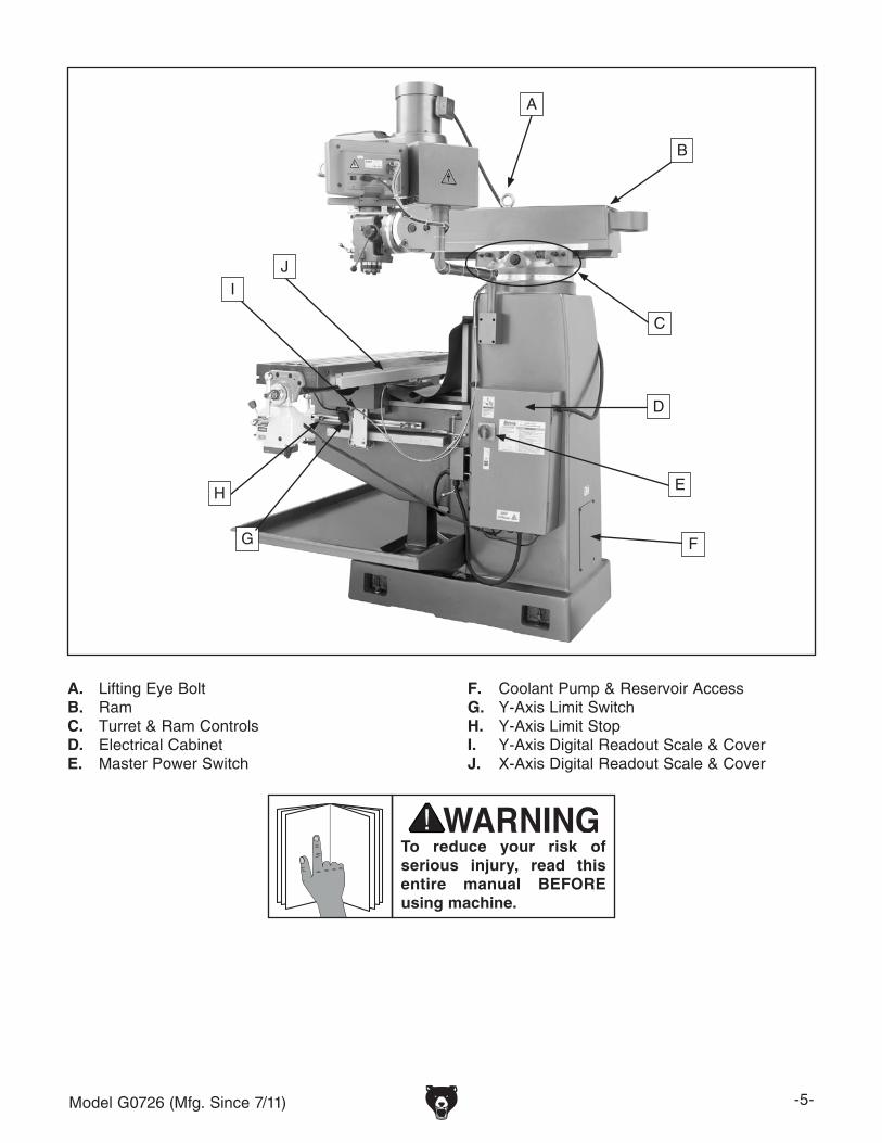
A. Lifting Eye BoltB. RamC. Turret & Ram ControlsD. Electrical CabinetE. Master Power Switch
F. Coolant Pump & Reservoir AccessG. Y-Axis Limit SwitchH. Y-Axis Limit StopI. Y-Axis Digital Readout Scale & CoverJ. X-Axis Digital Readout Scale & Cover
To reduce your risk of serious injury, read this entire manual BEFORE using machine.
F. KneeG. One-Shot OilerH. Z-Axis MotorI. Coolant Return Hose
A
B
C
D
E
F
G
H
I
Model G0726 (Mfg. Since 7/11) -7-
The information contained herein is deemed accurate as of 4/5/2017 and represents our most recent product specifications.Due to our ongoing improvement efforts, this information may not accurately describe items previously purchased. PAGE 1 OF 3Model G0726
MACHINE DATASHEET
Customer Service #: (570) 546-9663 · To Order Call: (800) 523-4777 · Fax #: (800) 438-5901
MODEL G0726 12" X 54" MILLING MACHINEProduct Dimensions:
Weight............................................................................................................................................................ 3960 lbs.Width (side-to-side) x Depth (front-to-back) x Height..................................................................... 55-5/8 x 61 x 93 in.Footprint (Length x Width)..................................................................................................................... 51 x 24-1/4 in.Space Required for Full Range of Movement (Width x Depth).................................................................. 100 x 72 in.
Shipping Dimensions:
Type.......................................................................................................................................................... Wood CrateContent........................................................................................................................................................... MachineWeight............................................................................................................................................................ 3750 lbs.Length x Width x Height....................................................................................................................... 70 x 75 x 91 in.Must Ship Upright................................................................................................................................................... Yes
Type........................................................................................................................................... TEFC InductionHorsepower................................................................................................................................................ 5 HPPhase.................................................................................................................................................... 3-PhaseAmps......................................................................................................................................................... 14.2ASpeed................................................................................................................................................ 1725 RPMPower Transfer .......................................................................................... Belt Drive w/Variable-Speed PulleyBearings..................................................................................................... Shielded & Permanently Lubricated
Table Elevation
Type........................................................................................................................................... TEFC InductionHorsepower............................................................................................................................................. 1/2 HPPhase.................................................................................................................................................... 3-PhaseAmps........................................................................................................................................................... 1.5APower Transfer ............................................................................................................................... Direct DriveBearings..................................................................................................... Shielded & Permanently Lubricated
Machine Data Sheet
-8- Model G0726 (Mfg. Since 7/11)
The information contained herein is deemed accurate as of 4/5/2017 and represents our most recent product specifications.Due to our ongoing improvement efforts, this information may not accurately describe items previously purchased. PAGE 2 OF 3Model G0726
Country of Origin ................................................................................................................................................ ChinaWarranty ........................................................................................................................................................... 1 YearApproximate Assembly & Setup Time .............................................................................................................. 1 HourSerial Number Location ............................................................................................................. Label on Electric BoxISO 9001 Factory .................................................................................................................................................. YesCertified by a Nationally Recognized Testing Laboratory (NRTL) .......................................................................... No
Model G0726 (Mfg. Since 7/11) -9-
ELECTRICAL EQUIPMENT INJURY RISKS. You can be shocked, burned, or killed by touching live electrical components or improperly grounded machinery. To reduce this risk, only allow qualified service personnel to do electrical installation or repair work, and always disconnect power before accessing or exposing electrical equipment.
DISCONNECT POWER FIRST. Always discon-nect machine from power supply BEFORE making adjustments, changing tooling, or servicing machine. This prevents an injury risk from unintended startup or contact with live electrical components.
EYE PROTECTION. Always wear ANSI-approved safety glasses or a face shield when operating or observing machinery to reduce the risk of eye injury or blindness from flying particles. Everyday eyeglasses are not approved safety glasses.
OWNER’S MANUAL. Read and understand this owner’s manual BEFORE using machine.
TRAINED OPERATORS ONLY. Untrained oper-ators have a higher risk of being hurt or killed. Only allow trained/supervised people to use this machine. When machine is not being used, dis-connect power, remove switch keys, or lock-out machine to prevent unauthorized use—especially around children. Make workshop kid proof!
DANGEROUS ENVIRONMENTS. Do not use machinery in areas that are wet, cluttered, or have poor lighting. Operating machinery in these areas greatly increases the risk of accidents and injury.
MENTAL ALERTNESS REQUIRED. Full mental alertness is required for safe operation of machin-ery. Never operate under the influence of drugs or alcohol, when tired, or when distracted.
For Your Own Safety, Read Instruction Manual Before Operating This Machine
The purpose of safety symbols is to attract your attention to possible hazardous conditions. This manual uses a series of symbols and signal words intended to convey the level of impor-tance of the safety messages. The progression of symbols is described below. Remember that safety messages by themselves do not eliminate danger and are not a substitute for proper accident prevention measures. Always use common sense and good judgment.
Indicates a potentially hazardous situation which, if not avoided, MAY result in minor or moderate injury. It may also be used to alert against unsafe practices.
Indicates a potentially hazardous situation which, if not avoided, COULD result in death or serious injury.
Indicates an imminently hazardous situation which, if not avoided, WILL result in death or serious injury.
This symbol is used to alert the user to useful information about proper operation of the machine.NOTICE
Like all machinery there is potential danger when operating this machine. Accidents are frequently caused by lack of familiarity or failure to pay attention. Use this machine with respect and caution to decrease the risk of operator injury. If normal safety pre-cautions are overlooked or ignored, seri-ous personal injury may occur.
No list of safety guidelines can be com-plete. Every shop environment is different. Always consider safety first, as it applies to your individual working conditions. Use this and other machinery with caution and respect. Failure to do so could result in serious personal injury, damage to equip-ment, or poor work results.
UNDERSTANDING CONTROLS: The mill is a complex machine that presents severe cutting or amputation hazards if used incorrectly. Make sure you understand the use and operation of all con-trols before you begin milling.
SAFETY ACCESSORIES: Flying chips or debris from the cutting operation can cause eye injury or blindness. Always use safety glasses or a face shield when milling.
WORK HOLDING: Before starting the machine, be certain the workpiece has been properly clamped to the table. NEVER hold the workpiece by hand during operation. Milling a workpiece that is not properly secured to the table or in a vise could cause the workpiece to be ejected at the operator with deadly force!
SPINDLE SPEED: To avoid tool or workpiece breakage that could send flying debris at the operator and bystanders, use the correct spindle speed for the operation. Allow the spindle to gain full speed before beginning the cut.
CHIP CLEANUP: Chips from the operation are sharp and hot. Touching them can cause burns or cuts. Using compressed air to clear chips could cause them to fly into your eyes, and may drive them deep into the working parts of the machine. Use a brush or vacuum to clear away chips and debris from machine or workpiece and NEVER clear chips while spindle is turning.
STOPPING SPINDLE: To reduce the risk of hand injuries or entanglement hazards, DO NOT attempt to stop the spindle with your hand or a tool. Allow the spindle to stop on its own or use the spindle brake.
SPINDLE DIRECTION CHANGE: Changing spindle rotation direction while it is spinning could lead to impact injury from broken tool or workpiece debris, as well as workpiece or machine damage. ALWAYS make sure the spindle is at a complete stop before changing spindle direction.
MACHINE CARE & MAINTENANCE: Operating the mill with excessively worn or damaged machine parts increases risk of machine or workpiece breakage which could eject hazardous debris at the operator. Operating a mill in poor condition will also reduce the quality of the results. To reduce this risk, maintain the mill in proper working con-dition by ALWAYS promptly performing routine inspections and maintenance.
CUTTING TOOL USAGE: Cutting tools have very sharp leading edges—handle them with care! Using cutting tools that are in good condi-tion helps to ensure quality milling results and reduces risk of personal injury from broken tool debris. Inspect cutting tools for sharpness, chips, or cracks before each use, and ALWAYS make sure cutting tools are firmly held in place before starting the machine.
-12- Model G0726 (Mfg. Since 7/11)
SECTION 2: POWER SUPPLY
AvailabilityBefore installing the machine, consider the avail-ability and proximity of the required power supply circuit. If an existing circuit does not meet the requirements for this machine, a new circuit must be installed. To minimize the risk of electrocution, fire, or equipment damage, installation work and electrical wiring must be done by an electrican or qualified service personnel in accordance with all applicable codes and standards.
Electrocution, fire, or equipment damage may occur if machine is not correctly grounded and connected to the power supply.
Full-Load Current RatingThe full-load current rating is the amperage a machine draws at 100% of the rated output power. On machines with multiple motors, this is the amperage drawn by the largest motor or sum of all motors and electrical devices that might operate at one time during normal operations.
Full-Load Current Rating at 220V .. 15.7 Amps
The full-load current is not the maximum amount of amps that the machine will draw. If the machine is overloaded, it will draw additional amps beyond the full-load rating.
If the machine is overloaded for a sufficient length of time, damage, overheating, or fire may result—especially if connected to an undersized circuit. To reduce the risk of these hazards, avoid over-loading the machine during operation and make sure it is connected to a power supply circuit that meets the requirements in the following section.
Circuit Requirements for 220VThis machine is prewired to operate on a 220V power supply circuit that has a verified ground and meets the following requirements:
For your own safety and protection of property, consult an electrician if you are unsure about wiring practices or electrical codes in your area.
Note: The circuit requirements listed in this man-ual apply to a dedicated circuit—where only one machine will be running at a time. If this machine will be connected to a shared circuit where mul-tiple machines will be running at the same time, consult a qualified electrician to ensure that the circuit is properly sized for safe operation.
A power supply circuit includes all electrical equipment between the breaker box or fuse panel in the building and the machine. The power sup-ply circuit used for this machine must be sized to safely handle the full-load current drawn from the machine for an extended period of time. (If this machine is connected to a circuit protected by fuses, use a time delay fuse marked D.)
Model G0726 (Mfg. Since 7/11) -13-
Extension CordsWe do not recommend using an extension cord with this machine. If you must use an extension cord, only use it if absolutely necessary and only on a temporary basis.
Extension cords cause voltage drop, which may damage electrical components and shorten motor life. Voltage drop increases as the extension cord size gets longer and the gauge size gets smaller (higher gauge numbers indicate smaller sizes).
Any extension cord used with this machine must contain a ground wire, match the required plug and receptacle, and meet the following require-ments:
Minimum Gauge Size ...........................12 AWGMaximum Length (Shorter is Better).......50 ft.
Grounding InstructionsThis machine MUST be grounded. In the event of certain malfunctions or breakdowns, grounding reduces the risk of electric shock by providing a path of least resistance for electric current.
Figure 1. Typical 15-20 plug and receptacle.
Grounding Pin
CurrentCarryingBlades
GroundedOutlet Box
Improper connection of the equipment-grounding wire can result in a risk of electric shock. The wire with green insulation (with or without yellow stripes) is the equipment-grounding wire. If repair or replacement of the power cord or plug is nec-essary, do not connect the equipment-grounding wire to a live (current carrying) terminal. Check with a qualified electrician or service per-sonnel if you do not understand these grounding requirements, or if you are in doubt about whether the tool is properly grounded. If you ever notice that a cord or plug is damaged or worn, discon-nect it from power, and immediately replace it with a new one.
Serious injury could occur if you connect the machine to power before completing the setup process. DO NOT connect to power until instructed later in this manual.
The power cord and plug specified under “Circuit Requirements for 220V” on the previous page has an equipment-grounding wire and a ground-ing prong. The plug must only be inserted into a matching receptacle (outlet) that is properly installed and grounded in accordance with all local codes and ordinances (see figure below).
No adapter should be used with the required plug. If the plug does not fit the available receptacle, or the machine must be reconnected for use on a different type of circuit, the reconnection must be made by a qualified electrician and comply with all local codes and ordinances.
-14- Model G0726 (Mfg. Since 7/11)
SECTION 3: SETUP
The following are needed to complete the setup process, but are not included with your machine.
Description Qty• Safety Glasses ........................................... 1• Cleaner/Degreaser ..................... As Needed• Disposable Shop Rags ............... As Needed• Power Lifting Equipment, Lifting Straps,
Lifting Chain & Safety Hook (rated for at least 4500 lbs. each)............... 1• Additional People ....................................... 2• Wrench 14mm ............................................ 1• Straightedge 4' ........................................... 1• Precision Level ........................................... 1
Needed for SetupThis machine presents serious injury hazards to untrained users. Read through this entire manu-al to become familiar with the controls and opera-tions before starting the machine!
Wear safety glasses dur-ing the entire setup pro-cess!
Your machine was carefully packaged for safe transportation. Remove the packaging materials from around your machine and inspect it. If you discover any damage, please call us immediately at (570) 546-9663 for advice.
Save the containers and all packing materials for possible inspection by the carrier or its agent. Otherwise, filing a freight claim can be difficult.
When you are completely satisfied with the condi-tion of your shipment, inventory the contents.
Unpacking
SUFFOCATION HAZARD!Keep children and pets away from plastic bags or packing materials shipped with this machine. Discard immediately.
The Model G0726 is a heavy machine. Serious personal injury may occur if safe moving methods are not used. To be safe, get assistance and use power equipment rated for at least 4500 lbs. to move the ship-ping crate and remove the machine from the crate.
Model G0726 (Mfg. Since 7/11) -15-
Inventory
The following is a list of items shipped with your machine. Before beginning setup, lay these items out and inventory them.
If any non-proprietary parts are missing (e.g. a nut or a washer), we will gladly replace them; or for the sake of expediency, replacements can be obtained at your local hardware store.
NOTICEIf you cannot find an item on this list, care-fully check around/inside the machine and packaging materials. Often, these items get lost in packaging materials while unpack-ing or they are pre-installed at the factory.
Description: (Figure 2) QtyA. Front Way Cover ......................................... 1B. Rear Way Cover ......................................... 1C. Drawbar 5⁄8"-11 x 11" ................................... 1D. Fine Downfeed Handle ............................... 1E. Ball Handles (X-Axis) ................................. 2F. Ball Handle (Y-Axis) ................................... 1G. Auto-Downfeed Direction Pin ..................... 1H. Toolbox ....................................................... 1I. Ball Handle Handles ................................... 3J. Bottle for Oil ............................................... 1K. Z-Axis Crank ............................................... 1L. Hex Wrench Set 1.5-10mm ........................ 1M. Coarse Downfeed Handle .......................... 1N. Screwdrivers Slotted #2, Phillips #2 ..1 EachO. Wrench 18 x 21mm Closed-Ends ............... 1P. Wrench 17 x 19mm Closed-Ends ............... 1Q. Splash Pan ................................................. 1R. Coolant Return Hose w/Clamp ................... 1
Figure 2. Small item inventory.
AB
C D
FE
H
I
K
N
Q
R
O
P
M
L
J
G
The toolbox and other small parts are inside the base of the column. You must remove the coolant pump access panel and the coolant pump from the rear of the column to access these items.
-16- Model G0726 (Mfg. Since 7/11)
The unpainted surfaces of your machine are coated with a heavy-duty rust preventative that prevents corrosion during shipment and storage. This rust preventative works extremely well, but it will take a little time to clean.
Be patient and do a thorough job cleaning your machine. The time you spend doing this now will give you a better appreciation for the proper care of your machine's unpainted surfaces.
There are many ways to remove this rust preven-tative, but the following steps work well in a wide variety of situations. Always follow the manufac-turer’s instructions with any cleaning product you use and make sure you work in a well-ventilated area to minimize exposure to toxic fumes.
Before cleaning, gather the following:• Disposable Rags• Cleaner/degreaser (WD•40 works well)• Safety glasses & disposable gloves• Plastic paint scraper (optional)
Basic steps for removing rust preventative:
1. Put on safety glasses.
2. Coat the rust preventative with a liberal amount of cleaner/degreaser, then let it soak for 5–10 minutes.
3. Wipe off the surfaces. If your cleaner/degreas-er is effective, the rust preventative will wipe off easily. If you have a plastic paint scraper, scrape off as much as you can first, then wipe off the rest with the rag.
4. Repeat Steps 2–3 as necessary until clean, then coat all unpainted surfaces with a quality metal protectant to prevent rust.
Gasoline or products with low flash points can explode or cause fire if used to clean machin-ery. Avoid cleaning with these products.
Many cleaning solvents are toxic if concentrat-ed amounts are inhaled. Only work in a well-venti-lated area.
NOTICEAvoid chlorine-based solvents, such as acetone or brake parts cleaner, that may damage painted surfaces. Test all cleaners in an inconspicuous area before using to make sure they will not damage paint.
Cleanup
T23692—Orange Power DegreaserA great product for removing the waxy shipping grease from your machine during clean up.
Figure 3. T23692 Orange Power Degreaser.
Model G0726 (Mfg. Since 7/11) -17-
Site Considerations
Figure 4. Minimum working clearances.
72"
100"
Wall
30"Minimum
Weight LoadRefer to the Machine Data Sheet for the weight of your machine. Make sure that the surface upon which the machine is placed will bear the weight of the machine, additional equipment that may be installed on the machine, and the heaviest work-piece that will be used. Additionally, consider the weight of the operator and any dynamic loading that may occur when operating the machine.
Space AllocationConsider the largest size of workpiece that will be processed through this machine and provide enough space around the machine for adequate operator material handling or the installation of auxiliary equipment. With permanent installations, leave enough space around the machine to open or remove doors/covers as required by the main-tenance and service described in this manual. See below for required space allocation.
Physical EnvironmentThe physical environment where the machine is operated is important for safe operation and lon-gevity of machine components. For best results, operate this machine in a dry environment that is free from excessive moisture, hazardous chemi-cals, airborne abrasives, or extreme conditions. Extreme conditions for this type of machinery are generally those where the ambient temperature range exceeds 41°–104°F; the relative humidity range exceeds 20–95% (non-condensing); or the environment is subject to vibration, shocks, or bumps.
Electrical InstallationPlace this machine near an existing power source. Make sure all power cords are protected from traffic, material handling, moisture, chemicals, or other hazards. Make sure to leave access to a means of disconnecting the power source or engaging a lockout/tagout device, if required.
LightingLighting around the machine must be adequate enough that operations can be performed safely. Shadows, glare, or strobe effects that may distract or impede the operator must be eliminated.
Children or untrained people may be seriously injured by this machine. Only install in an access restricted location.
-18- Model G0726 (Mfg. Since 7/11)
Lifting & Placing Mill
Lifting and placing the mill requires at least two other people for assistance and a forklift with two lifting straps, lifting chain, and a safety hook rated for at least 4500 lbs. each.
To lift and move the mill:
1. Position ram and headstock as illustrated in Figure 5 (refer to Head Movement on Page 32 and Ram Movement on Page 33 for detailed instructions).
Note: After re-positioning ram and head-stock, make sure they are locked in place to prevent unexpected movement during lifting and moving.
2. Place lifting straps under ram and connect them to forklift safety hook and chain, as illus-trated in Figure 6.
Note: Place padding between straps and mill to protect ram and ways, and to keep from cutting lifting straps.
3. Unbolt mill from shipping pallet.
4. With your assistants steadying the mill to keep it from swaying, lift mill a couple of inches.
— If mill tips to one side, lower it to the ground and adjust ram or table to balance load. Make sure to re-tighten lock levers and bolts before lifting mill again.
— If mill lifts evenly, continue to move it to its permanent location.
The Model G0726 is a heavy machine. Serious personal injury may occur if safe moving methods are not used. To be safe, get assistance and use power equipment rated for at least 4500 lbs. to move the ship-ping crate and remove the machine from the crate.
Figure 5. Correct ram and head position before lifting.
Figure 6. Lifting straps attached to safety hook and chain in preparation for lifting.
Safety Hook& Chain
LiftingStraps
Model G0726 (Mfg. Since 7/11) -19-
Leveling
Leveling machinery helps precision components, such as dovetail ways, remain straight and flat during the lifespan of the machine. Components on an unleveled machine may slowly twist due to the dynamic loads placed on the machine during operation.
Use metal shims between the base and the floor when leveling the machine.
For best results, use a precision level that is at least 12" long and sensitive enough to show a distance movement when a 0.003" shim (approxi-mately the thickness of one sheet of standard newspaper) is placed under one end of the level.
See Figure 7 for an example of a high precision level provided by Grizzly.
Figure 7. Model H2683 12" Master Machinist's Level.
Anchoring machinery to the floor prevents tipping or shifting and reduces vibration that may occur during operation, resulting in a machine that runs slightly quieter and feels more solid.
If the machine will be installed in a commercial or workplace setting, or if it is permanently connect-ed (hardwired) to the power supply, local codes may require that it be anchored to the floor.
If not required by any local codes, fastening the machine to the floor is an optional step. If you choose not to do this with your machine, we rec-ommend placing it on machine mounts, as these provide an easy method for leveling and they have vibration-absorbing pads.
Anchoring to Floor
Lag shield anchors with lag screws (see below) are a popular way to anchor machinery to a con-crete floor, because the anchors sit flush with the floor surface, making it easy to unbolt and move the machine later, if needed. However, anytime local codes apply, you MUST follow the anchoring methodology specified by the code.
Machine Base
Concrete
Lag Screw
Lag Shield Anchor
Flat Washer
Drilled Hole
Figure 8. Popular method for anchoring machinery to a concrete floor.
Anchoring to Concrete Floors
-20- Model G0726 (Mfg. Since 7/11)
Assembly
To assemble the mill:
1. Remove pre-installed hex nuts from leadscrew ends, align ball handle keyways with leadscrew keys as you slide ball handles on, then secure them with hex nuts (see Figure 9).
Note: Tighten hex nuts just until they are snug. Overtightening could increase the wear of moving parts.
2. Thread handles into small end of the ball handles and tighten them with 14mm wrench.
3. Remove cap screw and spacer from Z-axis leadscrew end, slide crank onto shaft as shown in Figure 10, then re-install cap screw and spacer.
4. Move table all the way forward, then attach rear way cover with the four pre-installed cap screws, as shown in Figure 11.
5. Move table all the way back toward the col-umn, then attach front way cover with the five pre-installed cap screws, as shown in Figure 12.
6. Raise knee with Z-axis crank, remove the four pre-installed cap screws from both sides of column (see Figure 13).
Figure 13. Splash pan installed.
Splash Pan
Cap Screws(2 of 4)
7. Slide splash pan onto machine base, then secure it in place with cap screws removed in Step 6.
Figure 12. Front way cover installed.
Cap Screws
8. Attach one end of coolant return hose to table connector with the pre-installed hose clamp, as shown in Figure 14.
9. Tug coolant return hose to make sure that it is securely attached. If it is not, repeat Step 8 until it is.
10. Loosen hose clamp cap screw on base (see Figure 14), slide other end of coolant return hose underneath it, then re-tighten cap screw.
11. Install coarse downfeed lever and fine downfeed handwheel, as shown in Figure 15.
Note: Make sure pins on the back of these devices are fully seated in the hubs.
12. Thread auto-downfeed direction pin into hub of fine downfeed handwheel (see Figure 15).
Figure 14. Coolant return hose attached to table.
HoseClamps
CoolantReturn Hose
Figure 15. Downfeed controls installed.
Auto-DownfeedDirection Pin
Fine DownfeedHandwheel
CoarseDownfeed Lever
CapScrew
-22- Model G0726 (Mfg. Since 7/11)
Power Connection
Before the machine can be connected to the power source, an electrical circuit must be made available that meets the minimum specifications given in Circuit Requirements for 220V on Page 12. If a power circuit has not been prepared for the machine, do that now.
To ensure a safe and code-compliant setup, all electrical work must be done by an electrician or qualified service personnel.
To connect the power supply to the mill:
1. Turn master power switch OFF (see Figure 16), then press latch to open electri-cal cabinet door.
Figure 16. Master power switch location.
ElectricalCabinetMaster
PowerSwitch
2. Install a strain relief in available hole in bot-tom of electrical cabinet (see Figure 17), then pull incoming power cord through strain relief.
3. Connect incoming hot wires to the bottom of the first three terminal bar connectors shown in Figure 17, then connect incoming ground wire to grounding bar (refer to the Electrical Cabinet Wiring Diagram on Page 57 for additional details).
4. Leave slack in the wires inside cabinet, tight-en strain relief to secure the cord, then tug on power cord outside electrical cabinet to make sure wires do not move inside cabinet.
— If wires do move when you tug on power cord outside electrical cabinet, disconnect the wires, reposition cord, then tighten the strain relief so that the cord will not move when tugged on. Re-connect wires as instructed in Step 3.
5. Close and lock electrical cabinet door.
Figure 17. Incoming power connections.
Grounding BarConnection Connect Incoming
Hot Wires Here
Model G0726 (Mfg. Since 7/11) -23-
Test Run
Once the assembly is complete, test run your machine to make sure it runs properly and is ready for regular operation.
During the test run, you will verify the proper operation of the following:
• Spindle motor• EMERGENCY STOP button• Z-axis power feed• Coolant pump• X- and Y-axis power feeds
If, during the test run, you cannot easily locate the source of an unusual noise or vibration, stop using the machine immediately, then review Troubleshooting on Page 50.
If you still cannot remedy a problem, contact our Tech Support at (570) 546-9663 for assistance.
Test Run the Mill1. Make sure you understand safety instructions
at beginning of manual and machine is setup properly.
2. Make sure all tools and objects used during setup are cleared away from machine.
3. Lubricate mill, as instructed in Lubrication on Page 45.
4. Fill coolant reservoir (refer to Coolant on Page 48 for detailed instructions).
5. Make sure speed range selector is in the low position (refer to Adjusting Spindle Speed on Page 35 for detailed instructions).
6. Turn MASTER POWER SWITCH (located on the electrical cabinet door) ON to enable power to the control panel—POWER LAMP should illuminate (see Figure 18).
7. Push EMERGENCY STOP button on control panel, then twist it clockwise so it pops out. When button pops out, it is reset and mill is ready for operation.
8. Move the downfeed selector to the forward position (disengage or manual) so spindle does not feed into table during this test (refer to Downfeed Controls on Page 36 for detailed instructions).
9. Turn SPINDLE SWITCH to the forward (FOR) position, then push START button to begin spindle rotation.
Figure 18. Control panel components.
CoolantSwitch
StartButton
PowerLamp
Emergency StopButton
Z-AxisDown Button
Z-AxisUp Button
SpindleSwitch
-24- Model G0726 (Mfg. Since 7/11)
15. WITHOUT resetting EMERGENCY STOP button, turn SPINDLE SWITCH to the for-ward (FOR) position and press START but-ton—machine should not start.
—If the machine does start (with EMERGENCY STOP button pushed in), turn MASTER POWER SWITCH OFF, then immedi-ately disconnect power to machine. The EMERGENCY STOP button safety feature is not working correctly. This safety feature must work properly before proceeding with regular operations. Call Tech Support for help.
16. Reset EMERGENCY STOP button, then press START button to start spindle rotation again.
17. Point coolant nozzle onto table, turn COOLANT SWITCH to "l" or ON, then open nozzle valve and check for proper operation of coolant system.
18. Turn coolant pump OFF, then turn SPINDLE SWITCH to STOP position to halt spindle rotation.
10. Verify that machine is operating correctly.
—When operating correctly, machine runs smoothly with little or no vibration or rub-bing noises.
— Investigate and correct strange or unusu-al noises or vibrations before operating machine further. Always stop machine and disconnect it from power before investigat-ing or correcting potential problems.
11. Rotate SPINDLE SWITCH to the STOP posi-tion and wait for spindle to completely stop.
12. Pull Z-axis crank away from limit switch to be able to properly perform the next step.
13. Verify power is not connected out of phase by using Z-axis UP and DOWN buttons on control panel to raise and lower knee.
—If knee moves opposite of button used, stop machine, disconnect machine from power, then swap any two of the three incoming power wires that connect to electrical box terminal bar (refer to Power Connection on Page 22 for detailed information).
14. Press EMERGENCY STOP button to turn machine OFF, then wait for spindle to stop on its own.
Model G0726 (Mfg. Since 7/11) -25-
Test Run X- & Y-Axis Power FeedsThe mill comes with a power feed units for the X- and Y-axis table travel. Proper operation of the limit switch attached to the front of the table is critical for the safe use of this power feed unit.
If the power feed does not operate as expected during the following steps, disconnect the mill from power and contact our Tech Support at (360) 734-1540 for assistance.
4. Make sure X-axis power feed directional lever is in the neutral (middle) position, turn speed dial counterclockwise to the lowest setting, then flip power switch to the ON (up) position.
5. Turn directional lever to left, then slowly turn speed dial clockwise to increase speed and confirm table moves.
6. Allow table limit stop to hit limit switch and turn power feed OFF, which will stop table movement.
7. Turn the directional lever through neutral (middle) position and to the right. The table should begin moving in the opposite direc-tion.
8. Confirm table stops moving again when limit stop presses against limit switch plunger.
9. Move directional lever to neutral (middle) position and flip power switch to OFF (down) position.
10. Test run Y-axis power feed in the same man-ner.
Congratulations! The Test Run is complete. Continue with the next page to perform the Spindle Break-In and Recommended Adjustments pro-cedures on the next page.
To test run the X- & Y-axis power feed:
1. Make sure all tools, cables, and other items are well clear of table movement as you fol-low these steps.
2. Refer to Table Movement, beginning on Page 29, to understand how power feeds, table locks, and limit switches function.
3. Loosen X- and Y-axis table locks on the front of table (see Figure 19).
The ball handles stay engaged with the leadscrews and could spin rapidly when using the power feeds. This could lead to impact injuries. Always stay clear of the ball handles when using the power feeds.
Figure 19. X- and Y-axis table locks.
Y-Axis Lock (1 of 2)
X-Axis Locks
-26- Model G0726 (Mfg. Since 7/11)
Spindle Bearing Break-In
Before operational loads are placed on the spin-dle bearings, complete this break-in procedure to fully distribute internal lubrication and reduce the risk of early failure.
To perform the spindle break-in procedure:
1. After successfully completing the Test Run procedure, make sure the spindle switch is in the OFF position and the spindle has come to a complete stop.
2. Move the spindle speed range selector to the LOW position (refer to Adjusting Spindle Speed on Page 35 for detailed instructions).
For your convenience, the adjustments listed below have been performed at the factory.
However, because of the many variables involved with shipping, we recommend that you at least verify the following adjustments to ensure the best possible results from your new machine.
Factory adjustments that should be verified:
1. Gib adjustment (Page 52).
2. Leadscrew backlash adjustment (Page 53).
Recommended Adjustments
6. Turn the spindle switch to OFF position, wait for the spindle to come to a complete stop, then move the spindle speed range selector to the HIGH position and start forward spindle rotation.
7. Set the spindle speed at approximately 2150 RPM, then repeat Steps 4–5.
8. Stop spindle rotation. The spindle break-in is now complete and the machine is ready for operation.
Do not leave the mill unattended during the Spindle Break-In procedure. If your atten-tion is needed elsewhere during this proce-dure, stop the mill and restart the procedure later from the beginning.
3. Turn the spindle switch to the forward posi-tion, press the start button, then use the vari-able speed handwheel to adjust the spindle speed to approximately 300 RPM.
4. Let the mill run at this speed for 20 minutes, then turn the spindle switch to the OFF posi-tion and allow the spindle to come to a com-plete stop.
5. Turn the spindle switch to the reverse (REV) position, press the start button, then let the mill run for another 20 minutes in reverse.
Failure to complete the spindle break-in process may lead to premature failure of the bearings—this will not be covered under warranty.
Model G0726 (Mfg. Since 7/11) -27-
SECTION 4: OPERATIONS
Operation Overview
The purpose of this overview is to provide the nov-ice machine operator with a basic understanding of how the machine is used during operation, so the machine controls/components discussed later in this manual are easier to understand.
Due to the generic nature of this overview, it is not intended to be an instructional guide. To learn more about specific operations, read this entire manual and seek additional training from expe-rienced machine operators, and do additional research outside of this manual by reading "how-to" books, trade magazines, or websites.
Damage to your eyes and lungs could result from using this machine without proper pro-tective gear. Always wear safety glasses and a respirator when operating this machine.
To reduce the risk of serious injury when using this machine, read and understand this entire manual before operating.
NOTICEIf you have never used this type of machine or equipment before, WE STRONGLY REC-OMMEND that you read books, review industry trade magazines, or get formal training before beginning any projects. Regardless of the content in this section, Grizzly Industrial will not be held liable for accidents caused by lack of training.
To complete a typical operation, the operator does the following:
1. Examines workpiece to make sure it is suit-able for milling.
2. Firmly clamps workpiece to table or a mill vise.
3. Installs correct cutting tool for operation.
4. Uses manual downfeed and table controls to correctly position cutting tool and workpiece for operation.
5. Puts on personal protective gear, and makes sure workpiece and table are clear of all tools, cords, and other items.
7. Turns mill OFF and waits for spindle to stop on its own before making adjustments or removing workpiece.
-28- Model G0726 (Mfg. Since 7/11)
Basic Controls
Refer to Figures 20–23 and the descriptions below to become familiar with the basic controls of the mill.
Master Power SwitchThe master power switch enables power to the control panel. Turning this switch OFF does NOT disconnect the mill from power.
Spindle Switch. Starts, stops, or reverses spin-dle rotation after START button is pressed.
Z-Axis Up & Down Buttons. Control Z-axis pow-ered movement.
Coolant Switch. Starts/stops the coolant pump.
Power Lamp. Lights when the master power switch is turned ON.
Start Button. Starts spindle rotation in the direc-tion selected by the spindle switch. You must press this button to enable all electrical compo-nents after resetting the emergency STOP button.
Emergency STOP Button. Cuts power to all mill components. Twist clockwise until it pops out to reset it and enable operations.
Work Lamp & Coolant Valve
Work Lamp. Illuminates the work area with a halogen light bulb that is controlled by the switch on the handle.
Coolant Valve. The lever on the coolant valve controls the flow of coolant to the nozzle.
Spindle Brake Lever
Spindle Brake Lever. Quickly brings the spindle to a stop after power is cut to the spindle motor.
Control Panel
Figure 21. Control panel components.
Figure 20. Master power switch.
MasterPowerSwitch
CoolantSwitch
StartButton
PowerLamp
Emergency StopButton
Z-AxisDown Button
Z-AxisUp Button
SpindleSwitch
Figure 22. Work lamp and coolant valve.
Work LampSwitch
CoolantValve
Figure 23. Spindle brake lever.
Spindle Brake Lever
Model G0726 (Mfg. Since 7/11) -29-
Table Movement
The table can be moved along three paths (see Figure 24) manually using ball handles or hand crank, or with the power feeds.
Y-Axis(In & Out)
Z-Axis(Up & Down)
X-Axis(Left & Right)
Figure 24. The three paths of movement of the table.
Digital ReadoutThe digital readout (see Figure 25) displays the exact positions of the table for X- and Y-axis paths.
Refer to the Digital Readout Manual included with your mill for operational instructions regard-ing the many functions of this unit.
Figure 25. Digital readout.
LocksUse the X-, Y-, and Z-axis locks shown in Figures 26–27 to hold the table in position when increased rigidity is needed.
Note: Remember to loosen the appropriate locks when table movement is needed in that direction.
Always keep the table locked in place unless controlled movement is required for your operation. Unexpected table movement dur-ing operations could cause the cutter to bind with the workpiece, which could result in damage to the cutter or workpiece.
Figure 26. X- and Y-axis locks.
X-Axis Locks
Y-Axis Lock (1 of 2)
Figure 27. Z-axis locks.
Z-AxisLocks
-30- Model G0726 (Mfg. Since 7/11)
X- & Y-Axis Power FeedsGraduated Dial Increments ResolutionEach Mark ................................................. 0.001"One Revolution ..........................................0.200"
Besides the ball handles for manual X- and Y-axis table movement, your mill is equipped with power feed systems for each of these paths. Refer to Figures 28–29 and the following descriptions to understand the functions of the power feed sys-tems.
A. Graduated Dial. Displays the distance of table travel.
B. Ball Handle. Manually moves the table along the path when rotated.
C. Dial Lock Collar. Locks the position of the graduated dial relative to the leadscrew. Loosen this collar to adjust the dial to a differ-ent setting, such as when zeroing it out.
D. Rapid Switch. Moves the table at maximum speed only while pressed.
E. Direction Lever: Controls the direction of travel, and stops movement when in the cen-ter position.
F. Speed Dial: Controls the rate of travel for the power feed.
G. Circuit Breaker Button. Pops out and cuts power to the unit when it is overloaded. Push the button to reset the circuit breaker.
H. Power Switch. Turns the unit ON and OFF.
I. X-Axis Limit Stops. Limits X-axis table movement.
J. X-Axis Limit Switch. Stops X-axis table movement when it engages one of the limit stops.
K. Y-Axis Limit Switch. Stops Y-axis table movement when it engages one of the limit stops.
L. Y-Axis Limit Stop (1 of 2). Limits Y-axis table movement.
1. Loosen appropriate table locks for the desired path of travel.
2. Loosen limit stop hex bolt or cap screw, posi-tion limit stop along slot to limit travel, then re-tighten fastener to secure it in place.
3. Rotate speed dial to slowest speed and set direction lever for desired direction of travel.
4. Use power switch to turn power feed ON, and adjust speed dial for desired feed rate.
5. When you are finished using power feed, position the direction lever to the center OFF position, then use power switch to turn unit OFF.
Stay clear of the spinning ball handles when using the power feeds to prevent entangle-ment injuries.
Z-Axis Crank & Power FeedGraduated Dial Increments ResolutionEach Mark ................................................. 0.001"One Revolution .......................................... 0.100"
When the vertical crank handle is engaged for manual operation, the safety switch below the crank disables the vertical power feed (see Figure 30).
Push the handle into the leadscrew to engage it for manual operation. Pull it out to dis-engage it from the safety switch, which enables the use of the vertical power feed buttons on the control panel.
Figure 30. Z-axis crank and safety switch.
Z-Axis Safety Switch
Crank
-32- Model G0726 (Mfg. Since 7/11)
Head Movement
The mill head tilts 45° back-and-forth, and rotates 90° from left-to-right (see Figures 31–32).
Tilting the HeadTool Needed QtyWrench or Socket 19mm ................................... 1
To tilt the head:
1. DISCONNECT MILL FROM POWER!
2. Loosen the three tilt locking bolts shown in Figure 33.
3. Supporting weight of head, slowly rotate the tilting bolt.
Note: Turn tilting bolt clockwise to tilt head back and counterclockwise to tilt it forward.
4. Re-tighten locking bolts to secure head in place.
Figure 31. Head tilted back 30°.
Figure 32. Head tilted to the left 45°.
Figure 33. Head tilting controls.
Locking Bolts& Scale
Tilting Bolt
The head is heavy. When tilting or rotating the head, get help to support the weight as you use the controls.
When the head has been tilted or rotated, you will need to tram the spindle with the table to ensure a 90° alignment. Refer to the Tramming Spindle section on Page 54 for detailed instructions.
Model G0726 (Mfg. Since 7/11) -33-
Rotating the HeadTools Needed QtyWrench or Socket 19mm ................................... 1Wrench or Socket 23mm ................................... 1
To rotate the head:
1. DISCONNECT MILL FROM POWER!
2. Loosen the four hex nuts behind head plate (see Figure 34).
3. Supporting weight of head, slowly turn rota-tion bolt.
Note: Turn rotation bolt clockwise to rotate head left and counterclockwise to rotate it right.
4. Re-tighten hex nuts to secure head in place.
Figure 34. Head rotation controls.
Rotation Bolt
HexNut
Always lock the head firmly in place after adjusting the tilt or rotation. Unexpected movement of the head during operations could cause the cutter to bind with the workpiece, which could result machine or workpiece damage.
Ram Movement
The ram moves back-and-forth horizontally and rotates 360° around the column.
Moving Ram Back & Forth1. DISCONNECT MILL FROM POWER!
2. Loosen the two locking bolts shown in Figure 35.
3. Slowly turn adjustment bolt to move ram to desired position along horizontal scale.
Note: Turn adjustment bolt clockwise to move ram back and counterclockwise to move ram forward.
4. Re-tighten locking bolts to secure ram in place.
Figure 35. Ram horizontal movement controls.
Adjustment Bolt
Locking Bolts
Horizontal Scale
-34- Model G0726 (Mfg. Since 7/11)
Rotating the Ram1. DISCONNECT MILL FROM POWER!
2. Loosen the four locking bolts (see Figure 36). There are two bolts on each side of ram.
3. Push against the headstock to manually rotate ram around the column to desired posi-tion on rotation scale.
Note: Take care not to entangle or stretch electrical cabling as you move ram and head.
4. Re-tighten the four locking bolts to secure ram in place.
Figure 36. Ram rotation locking bolts.
Locking Bolts (2 of 4)
Rotation Scale
Always lock the ram firmly in place after adjusting its position. Unexpected move-ment of the ram and head during opera-tions could cause the cutter to bind with the workpiece, which could result in machine or workpiece damage.
Using the correct spindle speed is important for safe and satisfactory results, as well as maximiz-ing tool life.
To set the spindle speed for your operation, you will need to: 1) Determine the best spindle speed for the cutting task, and 2) configure the mill con-trols to produce the required spindle speed.
Determining Spindle SpeedMany variables affect the optimum spindle speed to use for any given operation, but the two most important are the recommended cutting speed for the workpiece material and the tool diameter, as noted in the formula shown in Figure 37.
Cutting speed, typically defined in feet per minute (FPM), is the speed at which the edge of a tool moves across the material surface.
A recommended cutting speed is an ideal speed for cutting a type of material in order to produce the desired finish and optimize tool life.
The books Machinery’s Handbook or Machine Shop Practice, and some internet sites, pro-vide excellent recommendations for which cutting speeds to use when calculating the spindle speed. These sources also provide a wealth of additional information about the variables that affect cutting speed and they are a good educational resource.
Also, there are a large number of easy-to-use spindle speed calculators that can be found on the internet. These sources will help you take into account the applicable variables in order to deter-mine the best spindle speed for the operation.
Spindle Speed
Cutting Speed* (SFM) x 4
Tool Diameter (in inches)= RPM
* Double if using carbide cutting tool
Figure 37. Spindle speed formula for mills.
Model G0726 (Mfg. Since 7/11) -35-
Adjusting Spindle Speed1. Make sure spindle switch is in the OFF posi-
tion and spindle is stopped.
2. Select the range in chart below that includes desired spindle speed.
Range RPM
Low Range 50–420
High Range 420–3750
Figure 38. Spindle speed ranges.
NOTICETo avoid damage to the drive system, make sure the spindle motor is turned OFF and the spindle is stopped BEFORE you change the spindle speed range.
Note: In the next step, make sure locking pin is seated in indent for desired speed range.
3. Press spindle speed range selector handle in toward head to retract locking pin and move selector (see Figure 39).
Note: Move handle to the forward position for high range, or move it to the rear position for low range.
As you move selector handle, it may be necessary to rotate the spindle by hand to engage gears.
4. Start spindle rotation, then rotate variable speed handwheel until desired spindle speed is displayed in speed readout window on head, shown in Figure 40.
Note: The window on the left is for low range, and the window on the right is for high range.
Always ensure the spindle is rotating BEFORE using the variable speed handwheel. Otherwise, the variable speed system can be damaged.
Figure 39. Spindle speed range selector.
Spindle Speed Range Selector
Figure 40. Variable speed handwheel and readout windows.
Variable Speed
Handwheel
Speed Readout Windows
-36- Model G0726 (Mfg. Since 7/11)
Spindle Downfeed
Spindle downfeed movement on the mill is con-trolled by three mechanisms: 1) The coarse downfeed lever for rapid spindle movement, 2) the fine downfeed handwheel for slower spindle movement, and 3) the auto-downfeed system for powered spindle movement.
Downfeed ControlsUse Figure 41 and the following descriptions to become familiar with the spindle downfeed con-trols.
A. Auto-Downfeed Rate Selector. Selects one of the three auto-downfeed rates.
B. Fine Downfeed Handwheel. Manually con-trols slow spindle downfeed.
C. Auto-Downfeed Direction Pin. Starts, stops, and reverses the auto-downfeed direction.
D. Fine Downfeed Clutch Lever. Engages the fine/auto-downfeed gears.
E. Downfeed Scale. Used with the quill dog, shows the depth of spindle downfeed in inches.
F. Quill Lock Lever. Secures the quill in place for increased stability during operations.
G. Downfeed Stop & Locking Wheel. Sets the depth of spindle downfeed. The stop is threaded into position, then the locking wheel is used to secure it in place.
H. Coarse Downfeed Lever. Manually controls quick spindle downfeed.
I. Quill Dog. Moves with the quill and spin-dle, and disengages the downfeed clutch lever when it contacts either the top or the downfeed stop.
J. Downfeed Selector. Sets the mill for manual downfeed or auto-downfeed control.
When spindle rotation is reversed, either by changing the spindle speed range or by using the spindle direction switch, the direc-tion of spindle auto-downfeed will reverse.
Figure 41. Downfeed controls.
A
I
J
H
G
F
E
D
C
B
Model G0726 (Mfg. Since 7/11) -37-
Coarse DownfeedUse the coarse downfeed lever to quickly move the spindle manually.
To use the coarse downfeed:
1. Make sure spindle is completely stopped.
2. Pull downfeed selector knob out, then rotate it clockwise until knob pin seats in the forward manual (disengaged) detent (see Figure 42).
Note: It may be necessary to turn spindle by hand as you move the selector to engage the gears.
Manual (Disengaged) Position
Auto-Downfeed (Engaged) PositionFigure 42. Downfeed selector in manual (disengaged) position.
3. Make sure pin of the coarse downfeed lever hub is engaged with one of the detents on hub (see Figure 43).
4. Make sure quill lock is loose so quill can move freely.
5. Rotate coarse downfeed lever around hub to control spindle depth.
Fine DownfeedThe fine downfeed handwheel provides a slower and more controlled method of spindle movement.
To use the fine downfeed:
1. Make sure spindle is completely stopped.
2. Pull downfeed selector knob out, then rotate it clockwise until knob pin seats in the forward manual (disengaged) detent (see Figure 42).
Note: It may be necessary to turn the spindle by hand as you move the selector to enable the gears to mesh.
3. Set auto-downfeed direction pin in the neutral (middle) position to disengage fine downfeed handwheel from auto-downfeed gears.
4. Position downfeed stop for desired spindle depth, then secure it in place with locking wheel.
5. Use coarse downfeed lever to lower spindle slightly until you can pull fine downfeed clutch lever out to the left and it locks in place. This will engage fine downfeed handwheel with quill and spindle.
6. To lower spindle, rotate fine downfeed handwheel. When quill dog meets downfeed stop, clutch lever will disengage and spindle will return to the top.
Figure 43. Coarse downfeed handle installed.
Hub
QuillLock
CoarseDownfeed
Lever
-38- Model G0726 (Mfg. Since 7/11)
Auto-DownfeedWhen using the auto-downfeed system, the spin-dle will move in the direction you choose with the auto-downfeed direction pin. When the quill dog reaches the top or meets the downfeed stop, the downfeed clutch lever will release. Then, if the spindle was traveling upward, the movement will simply stop. If the spindle was traveling down-ward, then the spindle will move back to the top at a rate controlled by the return spring on the left side of the head.
To use the auto-downfeed:
1. Make sure spindle is completely stopped.
2. Pull downfeed selector knob out, then rotate it clockwise until knob pin seats in the auto-downfeed (engaged) detent (see Figure 44).
Note: It may be necessary to turn spindle by hand as you move selector to engage gears.
3. Position downfeed stop for desired spindle depth, then secure it in place with locking wheel.
Manual (Disengaged) Position
Auto-Downfeed (Engaged) Position
Figure 44. Downfeed selector in auto-downfeed (engaged) position.
4. Position auto-downfeed direction pin in cen-ter of handwheel for desired direction of spin-dle travel. If necessary, rock fine downfeed handwheel back-and-forth to move pin all the way in or out.
Note: The direction pin has three positions (see Figure 45): 1) In for one downfeed direction, 2) middle for neutral or no move-ment, and 3) out for the reverse direction. The direction of spindle travel for in and out positions is relative to direction of spindle rotation. Keep in mind that spindle rotation and downfeed direction will reverse when the spindle speed range is changed.
To avoid damage to the system gearing, never use the auto-downfeed system with spindle speeds over 1750 RPM.
5. Make sure clutch lever is all the way to the right in the disengaged position so spindle will not travel when rotation is started.
Note: We recommend that you complete the remaining steps without a cutting tool installed, without a workpiece in place, and with the table lower than the maximum spindle downfeed travel. This will enable you to test and confirm settings before beginning actual cutting.
Fine Downfeed Handle
In forOne Direction
Out toReverse Direction
Middle for Neutral
Pin
Figure 45. Three positions of auto-downfeed direction pin.
Model G0726 (Mfg. Since 7/11) -39-
6. Set mill for the desired spindle speed, then begin spindle rotation.
7. Select one of the three downfeed rates by pulling knob of auto-downfeed rate selector out, position selector over appropriate detent, then release knob. Make sure pin is firmly seated by attempting to move selector with-out pulling knob out.
Note: Refer to the illustration in Figure 46 when selecting the downfeed rate.
8. Use coarse downfeed lever to lower spindle slightly until you can pull clutch lever out to the left and it locks in place, which will start auto-downfeed spindle travel.
ALWAYS start spindle rotation before chang-ing the auto-downfeed rate to avoid the risk of gear damage.
2. Clean any debris or oily substances from the mating surfaces of the NT40 tool holder and spindle tapers.
3. Align the spindle lugs with the slots on the tool holder, then push the tool firmly into the spindle taper to seat it (see Figure 48).
Figure 48. Cutting tool and holder installed into the spindle.
Cutter
Spindle Lug
NT40 Tool Holder
Cutting tools are sharp and can quickly injure your hands. Always protect your hands when handling cutting tools.
4. While holding the tool in place, insert the drawbar through the top of the spindle, as shown in Figure 49, then thread it into the tool.
Figure 49. Drawbar inserted through the top of the spindle.
5. Only tighten the drawbar into the tool holder until it is snug.
Note: Over-tightening the drawbar could make removing the tool holder from the spindle difficult.
Unloading Tooling1. DISCONNECT MILL FROM POWER!
2. Keep the spindle engaged with either the low or high speed range to stop the spindle from rotating.
3. Support the tool and holder with one hand, then completely un-thread the drawbar with the other.
— If the tool holder does not immediately release from the spindle taper when the drawbar is loosened, thread the drawbar back into the tool holder two complete turns, then tap the top of the drawbar with a dead-blow hammer or rubber mallet to break the tool holder loose.
Drawbar
Model G0726 (Mfg. Since 7/11) -41-
SECTION 5: ACCESSORIESACCESSORIES
Some aftermarket accessories can be installed on this machine that could cause it to function improperly, increasing the risk of serious personal injury. To minimize this risk, only install accessories recommended for this machine by Grizzly.
NOTICERefer to the newest copy of the Grizzly Catalog for other accessories available for this machine.
H8368—Electric Power DrawbarReduce your tool changing time to a fraction. This easy-to-use Power Drawbar kit will enable you to make tool changes in a flash on both manual and CNC milling machines. It has enough torque for tapers ranging from R-8 to NT50 and simple installation is supported by complete instructions. Specifications: Motor 220V, 7.5 maximum amper-age draw, 2100 RPM, and 240 ft/lbs.
Figure 50. H8368 electric power drawbar.
H5791—NT40 Quick Change Collet SetThis self-ejecting system offers quick change outs and precise, rigid control. This set comes supplied with an NT40 collet chuck, wrench and fitted plas-tic case. NT40 collets are sized 1⁄8", 1⁄4", 3⁄8", 1⁄2", 5⁄8", 3⁄4", 7⁄8" and 1".
Figure 51. H5791 NT40 Quick Change Collet Set.
order online at www.grizzly.com or call 1-800-523-4777
T23962—ISO 68 Moly-D Way Oil, 5 gal.T23963—ISO 32 Moly-D Machine Oil, 5 gal.Moly-D oils are some of the best we've found for maintaining the critical components of machinery because they tend to resist run-off and maintain their lubricity under a variety of conditions—as well as reduce chatter or slip. Buy in bulk and save with 5-gallon quantities.
Figure 52. ISO 68 and ISO 32 machine oil.
T23962 T23963
-42- Model G0726 (Mfg. Since 7/11)
G9299—10" Yuasa-Type Rotary TableThis high precision rotary table features extra deep coolant channels, dual positive action locks, very low profiles, 10 second vernier scales, gear drives with oil immersion and satin chrome dials. See the current Grizzly catalog for full specifica-tions. Features: 4.330" overall height (horizontal), 6.750" height to center hole (vertical), #3 Morse Taper, 0.465" T-slot width, and 117 lbs. approxi-mate shipping weight.
Figure 53. G9299 10" Yuasa-Type Rotary Table.
NT40 End Mill HoldersH5792—3⁄8"H5793—1⁄2"H5794—5⁄8"H5795—3⁄4"H5796—1"H5797—1 1⁄4"H5798—1 1⁄2"Sized to fit all common end mill shanks, these pre-cision NT40 end mill holders fit any NT40 taper.
Figure 54. NT40 End Mill Holder.
T10063—Milling Vise 125⁄16" x 69⁄16"T10064—Milling Vise 171⁄8" x 83⁄4"• Ultra precise in flatness, parallelism and ver-
ticality.• Anti-lift mechanism ensures the workpiece
does not lift when jaws are tightened.• Ductile iron body.• Flame hardened vise bed and jaws.• Sealed bearing system.• 8200 lbs. of clamping pressure.
Figure 55. T10064 Milling vise (handle included, but not shown.
order online at www.grizzly.com or call 1-800-523-4777
G9757—10-Piece 2-Flute HSS End Mill SetPriced for outstanding value, this 10-piece assort-ment of high-speed steel end mills feature the following sizes: 3⁄16", 1⁄4", 5⁄16", 3⁄8", 7⁄16", 1⁄2", 9⁄16", 5⁄8", 11⁄16". and 3⁄4". Finely-crafted mills are singled ended. Includes wooden storage case.
Figure 56. G9757 10-Piece HSS End Mill Set.
Model G0726 (Mfg. Since 7/11) -43-
H5802—NT40 to MT#2 SleeveH5803—NT40 to MT#3 SleeveH8139—NT40 to R8 Adapter
Figure 60. NT40 Sleeves and Adapter.
G5758—5" x 7" Tilt TableG5759—7" x 10" Tilt TableSet your work at any angle from –45° to +45° with these sturdy Tilt Tables. Heavy-duty construction includes T-slots, two locking screws, and preci-sion base with a scale.
Figure 57. Tilt Table.
G5641—1-2-3 BlocksG5642—2-4-6 BlocksThese blocks are extremely handy for layout and set up work. Matched blocks are hardened and precision ground so all six sides are square to within 0.0003". These blocks also feature five tapped holes and 18 untapped holes for clamping. Sold in pairs. G5641 tapped holes are 3⁄8"-16, and overall size is 1" x 2" x 3". G5642 tapped holes are 5⁄8" 11, and overall size is 2" x 4" x 6".
Figure 58. 1-2-3 and 4-5-6 Blocks.
G5678— Steel Parallel Sets 3⁄16" ThicknessG5678— Steel Parallel Sets 1⁄2" ThicknessThese ground and hardness sets feature four pairs of 6" long parallels which are accurate to within 0.0003" in parallelism and 0.0002" in height.
G1076—52-PC. Clamping Kit for 5⁄8" T-SlotsThis clamping kit includes 24 studs, 6 step block pairs, 6 T-nuts, 6 flange nuts, 4 coupling nuts, and 6 end hold-downs. The rack is slotted so it can be mounted close to the machine for easy access.
Figure 59. G1076 52-PC. Clamping Kit.
Figure 61. Steel parallel sets.
order online at www.grizzly.com or call 1-800-523-4777
-44- Model G0726 (Mfg. Since 7/11)
SECTION 6: MAINTENANCE
Always disconnect power to the machine before performing maintenance. Failure to do this may result in serious person-al injury.
Schedule
Regular maintenance will help ensure proper care of the equipment. We strongly recommend that all operators make a habit of following main-tenance procedures listed below. For optimum performance from this machine, this maintenance schedule must be strictly followed.
OngoingTo maintain a low risk of injury and proper machine operation, if you ever observe any of the items below, shut the machine down immediately, disconnect it from power, and fix the problem before continuing operations.
• Loose mounting bolts or fasteners.• Worn, frayed, cracked, or damaged wires.• Emergency STOP button not working cor-
rectly.• Missing belt guards.• Reduction in braking speed or efficiency.• Coolant not flowing correctly.• Any other unsafe condition.
Before Beginning Operations• Make sure the electric cabinet door is closed
and properly latched.• Turn the spindle direction switch to the OFF
position to prevent high-speed spindle start-up when connected to power.
• Move the downfeed selector to the manual position to prevent the spindle from unexpect-edly downfeeding when rotation is started.
• Make sure the X- and Y-axis power feeds are turned OFF to prevent unintentional table movement when connected to power.
• Check the coolant reservoir in the base. Fill it or clean it out if necessary.
• Perform all required lubrication tasks.• Check table movement in all three axes for
loose/tight gibs. Adjust the gibs if necessary.
Daily, After Operations• Push the emergency STOP button, turn the
master power switch OFF, and disconnect the machine from power.
• Vacuum/clean all chips and swarf from table, slides, and base.
• Wipe down all unpainted or machined sur-faces with a high-quality rust preventative.
Model G0726 (Mfg. Since 7/11) -45-
Cleaning & Protecting
Regular cleaning is one of the most important steps in taking good care of this machine. In most shops, each operator is responsible for cleaning the machine immediately after using it or at the end of the day. We recommend that the cleaning routine be planned into the workflow schedule, so that adequate time is set aside to do the job right.
Typically, the easiest way to clean swarf from the ways and table is to use a wet/dry shop vacuum that is dedicated for this purpose only. The small chips leftover after vacuuming can be wiped up with a slightly oiled rag. Avoid using compressed air to blow off chips, as it may drive them deeper into moving surfaces and could cause sharp chips to fly into your face or hands.
All visible swarf should be removed from the mill during cleaning.
Besides the ways, all other unpainted and machined surfaces should be wiped down daily to keep them rust-free and in top condition. This includes any surface that is vulnerable to rust if left unprotected (especially any parts that are exposed to water soluble coolant). Typically, a thin film of way oil is all that is necessary for protec-tion.
Lubrication
The mill has numerous moving metal-to-metal contacts that require regular and proper lubrica-tion to ensure efficient and long-lasting operation.
Other than the lubrication points covered in this section, all other bearings are internally lubricated and sealed at the factory. Simply leave them alone unless they need to be replaced.
DISCONNECT MILL FROM POWER before per-forming any lubrication task!
Important: Before adding lubricant, clean the debris and grime from the oil cup or grease fitting and the immediate area to prevent contamination of the oil cups, grease fittings, or new lubricant.
Use the schedule and information in the chart below as a daily guide for lubrication tasks.
Lubrication TaskFrequency (Hours of Operation)
Page Ref.
Quill Gearing 4–8 46
One-Shot Oiler (Table Ways & Leadscrews)
4–8 46
Bull Gear 40 46
Ram Ways 40 46
Z-Axis Leadscrew Bevel Gears
40 47
X- & Y-Axis Power Feed Gears
80 47
The recommended lubrication schedule is based on light-to-medium usage. Keeping in mind that lubrication helps to protect the value and operation of the mill, these lubrication tasks may need to be performed more frequently depending on usage.
-46- Model G0726 (Mfg. Since 7/11)
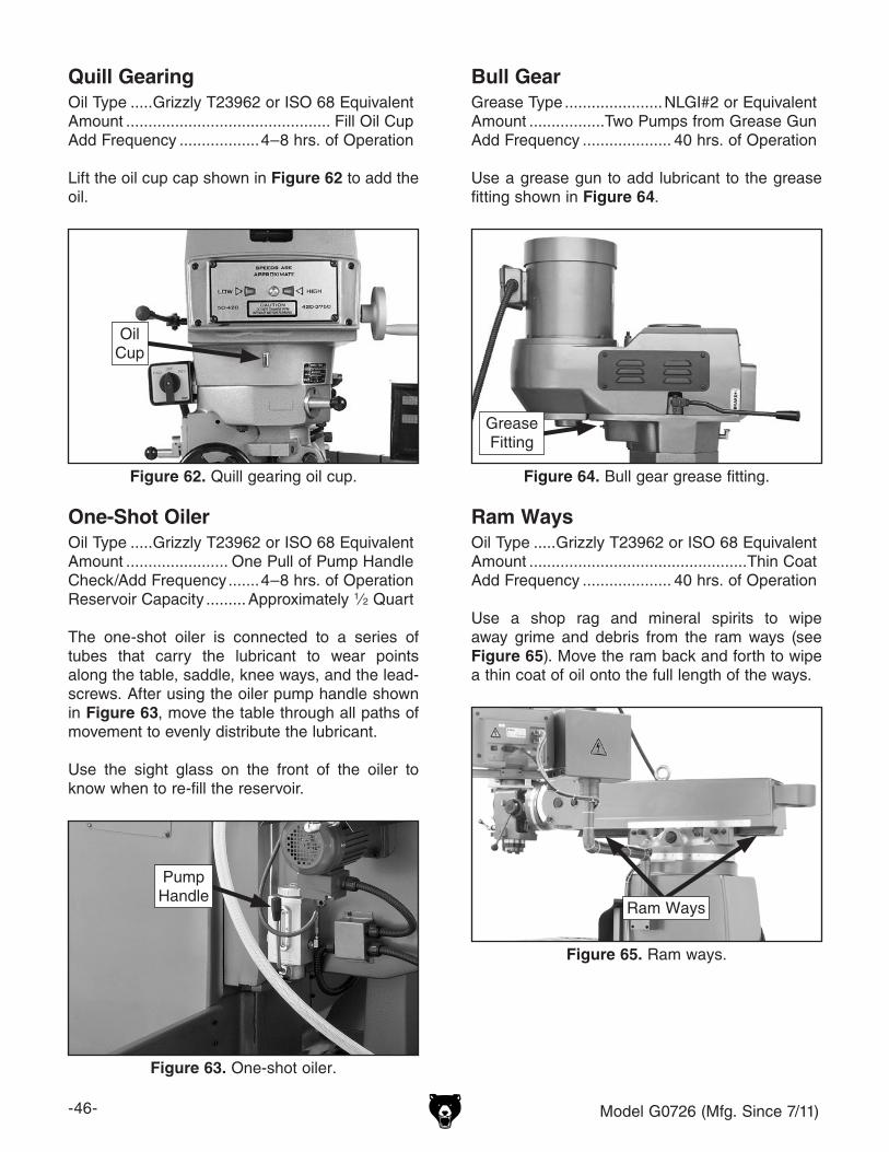
Quill GearingOil Type .....Grizzly T23962 or ISO 68 EquivalentAmount .............................................. Fill Oil CupAdd Frequency ..................4–8 hrs. of Operation
Lift the oil cup cap shown in Figure 62 to add the oil.
Bull GearGrease Type ......................NLGI#2 or EquivalentAmount .................Two Pumps from Grease GunAdd Frequency .................... 40 hrs. of Operation
Use a grease gun to add lubricant to the grease fitting shown in Figure 64.
Figure 62. Quill gearing oil cup.
OilCup
One-Shot OilerOil Type .....Grizzly T23962 or ISO 68 EquivalentAmount ....................... One Pull of Pump HandleCheck/Add Frequency .......4–8 hrs. of OperationReservoir Capacity .........Approximately 1⁄2 Quart
The one-shot oiler is connected to a series of tubes that carry the lubricant to wear points along the table, saddle, knee ways, and the lead-screws. After using the oiler pump handle shown in Figure 63, move the table through all paths of movement to evenly distribute the lubricant.
Use the sight glass on the front of the oiler to know when to re-fill the reservoir.
Figure 63. One-shot oiler.
Ram WaysOil Type .....Grizzly T23962 or ISO 68 EquivalentAmount .................................................Thin CoatAdd Frequency .................... 40 hrs. of Operation
Use a shop rag and mineral spirits to wipe away grime and debris from the ram ways (see Figure 65). Move the ram back and forth to wipe a thin coat of oil onto the full length of the ways.
Figure 65. Ram ways.
Ram Ways
PumpHandle
Figure 64. Bull gear grease fitting.
GreaseFitting
Model G0726 (Mfg. Since 7/11) -47-
Z-Axis Leadscrew Bevel GearsGrease Type ......................NLGI#2 or EquivalentAmount .................................................Thin CoatAdd Frequency .................... 40 hrs. of Operation
Use a clean, stiff brush and mineral spirits to clean away the old grease and grime from the bevel gears (see Figure 66), then brush a thin coat of grease onto and into the teeth of the gears.
X- & Z-Axis Power Feed GearsGrease Type ......................NLGI#2 or EquivalentAmount .................................................Thin CoatAdd Frequency .................... 40 hrs. of Operation
2. Remove hex nut and ball handle from power unit end of the X-axis leadscrew.
3. Unthread and remove knurled retaining ring and graduated dial ring from end of leadscrew.
Figure 67. Power feed gears and key.
BrassBevel Gear
DriveGear
Key
5. Brush a light coat of grease on bevel gear teeth and smaller drive gear.
6. Replace leadscrew alignment key, then align bevel gear keyway with key as you slide gear onto leadscrew and mesh its teeth with drive gear.
7. Replace graduated dial ring into position and secure it with knurled retaining ring—do not overtighten.
8. Slide ball handle onto leadscrew, align key-way with leadscrew alignment key, then secure it with hex nut removed in Step 2.
9. Move table with ball handle to check gear movement and distribute grease on gears. If the movement is not smooth, repeat Steps 2–8 until it is.
4. Remove brass bevel gear from leadscrew, then remove leadscrew alignment key (see Figure 67).
Figure 66. Z-Axis leadscrew bevel gears.
Bevel Gears(On Top of
Z-AxisLeadscrew)
-48- Model G0726 (Mfg. Since 7/11)
Coolant
HazardsAs some coolant ages, dangerous microbes can proliferate and create a biological hazard. The risk of exposure to this hazard can be greatly reduced by replacing the old coolant on a monthly basis, as indicated in the maintenance schedule.
The important thing to keep in mind when working with the coolant is to minimize exposure to your skin, eyes, and respiratory system by wearing the proper PPE (personal protective equipment), such as splash-resistant safety glasses, long-sleeve gloves, protective clothing, and a NIOSH approved respirator.
BIOLOGICAL & POISON HAZARD!
Use the correct personal protection equipment when handling coolant. Follow federal, state, and fluid manufacturer requirements for proper disposal.
A small amount of coolant is lost during normal operation. Check the coolant reservoir regularly and fill it if necessary. We recommend chang-ing the coolant every three months or sooner if it develops an unpleasant odor. However, be sure to follow the coolant manufacturer's instructions when checking, adding, or changing coolant.
The coolant reservoir holds approximately 6–7 gallons (22–27 liters) of fluid.
3. Use a clean metal tool as a dip stick to mea-sure level of coolant in the reservoir. If level is lower than 3", add coolant by pouring it through coolant drain screens on base of mill.
Note: Clean away debris and grime from drain screens and surrounding area before adding coolant.
4. Re-install access panel before resuming mill-ing operations.
Running the coolant pump without adequate coolant in the reservoir may permanently damage the coolant pump, which will not covered by the warranty.
Model G0726 (Mfg. Since 7/11) -49-
To change the coolant:
1. Put on personal protective equipment.
2. Place catch pan on table, position the coolant nozzle into pan, then use coolant pump to drain reservoir.
Note: When catch pan is near full, empty it into 5 gallon bucket, then repeat process.
Tip: Alternately, slide a rubber hose onto coolant nozzle and point it into 5 gallon buck-et.
3. DISCONNECT MILL FROM POWER!
4. Remove coolant reservoir access panel from the rear of column.
5. Remove the two pump mounting cap screws and move pump out of the way.
6. Thoroughly clean out bottom of the reservoir and the base of pump. Make sure interior is completely dry before adding new coolant.
Note: Use a cleaning solution that is compat-ible with type of coolant. For instance, if you are using a water-base coolant, then use a water-base cleaning solvent.
7. When reservoir and pump are clean and dry, replace the pump, and access panel.
Tip: Place a couple of magnets inside res-ervoir under return screens to collect metal particles to keep them out of coolant pump.
8. Clean away debris and grime from coolant drain screen on base of mill, then pour cool-ant through one of the screens to fill reser-voir.
Machine Storage
The mill must be properly prepared if it will be stored for any period of time. Doing this will help prevent the development of rust and corrosion and ensure the mill remains in good condition for later use.
Note: When taking the mill out of storage, repeat the Test Run and the Spindle Break-In.
To prepare the mill for storage:
1. DISCONNECT MILL FROM POWER!
2. Lubricate mill as directed in Lubrication beginning on Page 45.
3. Clean out coolant reservoir as directed in Changing Coolant on this page.
4. Thoroughly clean all unpainted, bare metal surfaces, then coat them with quality rust pre-ventative. Take care to ensure these surfaces are completely covered but rust preventative is kept off painted surfaces.
Note: If the machine will be out of service for only a short period of time, use way oil or a good grade of medium-weight machine oil (not auto engine oil) in place of rust preventa-tive.
5. Loosen belts to prevent them from stretching during storage. Post a reminder on mill that belts need to be re-installed or tensioned before resuming operations.
6. Place a few moisture-absorbing desiccant packs inside electrical cabinet.
7. Cover and place machine in a dry area that is out of direct sunlight and away from haz-ardous fumes, paint, solvents, or gas. Fumes and sunlight can bleach or discolor paint and plastic parts.
8. At least once a month, start mill and run all gear-driven components for a few minutes. This will keep bearings, bushings, gears, and shafts well lubricated and protected from cor-rosion.
-50- Model G0726 (Mfg. Since 7/11)
Review the troubleshooting and procedures in this section if a problem develops with your machine. If you need replacement parts or additional help with a procedure, call our Technical Support at (570) 546-9663. Note: Please gather the serial number and manufacture date of your machine before calling.
SECTION 7: SERVICE
Troubleshooting
Motor & Electrical
Symptom Possible Cause Possible SolutionMachine does not start or a breaker trips.
1. Emergency STOP button is pushed in or is at fault.
2. Plug/receptacle is at fault or wired incorrectly.
3. Power supply is switched OFF or is at fault.
4. Motor connection wired incorrectly.5. ON button is at fault.6. Motor windings or motor is at fault.
1. Turn the emergency STOP button clockwise until it pops out; replace if faulty.
2. Test for good contacts; correct the wiring.
3. Ensure hot lines have correct voltage on all legs and main power supply is switched ON.
4. Correct motor wiring connections.5. Replace faulty ON button.6. Replace motor.
Machine stalls or is overloaded.
1. Machine is undersized for the task.
2. Workpiece alignment is poor.
3. Dull or incorrect cutting tool.4. Gearbox is at fault.5. Motor connection is wired incorrectly.6. Plug/receptacle is at fault.7. Pulley/sprocket slipping on shaft.8. Motor bearings are at fault.
9. Motor has overheated.10. Motor is at fault.
1. Use smaller, sharper tooling; reduce the feed rate; reduce the spindle RPM; use coolant.
2. Eliminate workpiece binding; use vise or clamps as required for workpiece alignment control.
3. Use sharp and correct cutting tool for the operation.4. Replace broken or slipping gears.5. Correct motor wiring connections.6. Test for good contacts; correct the wiring.7. Replace loose pulley/shaft.8. Test by rotating shaft; rotational grinding/loose shaft
requires bearing replacement.9. Clean off motor, let cool, and reduce workload.10. Test and repair or replace.
Machine has vibration or noisy operation.
1. Tool holder or cutter is at fault.
2. Workpiece alignment is poor.
3. Motor or component is loose.
4. Pulley is loose.
5. Machine is incorrectly mounted or sits unevenly.
6. Motor fan is rubbing on fan cover.7. Motor bearings are at fault.
8. Gearbox is at fault.
1. Replace out-of-round tool holder; replace/resharpen cutter; use appropriate feed rate and cutting RPM.
2. Eliminate workpiece binding; use vise or clamps as required for workpiece alignment control.
3. Inspect/replace stripped or damaged bolts/nuts, and re-tighten with thread locking fluid.
4. Realign/replace shaft, pulley, setscrew, and key as required.
5. Tighten/replace mounting bolts in floor; relocate/shim machine.
6. Replace dented fan cover or fan.7. Test by rotating shaft; rotational grinding/loose shaft
requires bearing replacement.8. Rebuild gearbox for bad gear(s)/bearing(s).
Model G0726 (Mfg. Since 7/11) -51-
Operation
Symptom Possible Cause Possible SolutionTool slips in collet. 1. Collet is not fully drawn into spindle taper.
2. Wrong size collet.3. Debris on collet or spindle mating surface.
4. Excessive depth of cut.
1. Snug up drawbar.2. Use correct collet for shank diameter.3. Remove oil and debris from collet and spindle
mating surfaces, then re-install.4. Decrease depth of cut and allow chips to clear.
Breaking tooling. 1. Spindle speed/feed rate too fast.2. Tooling getting too hot.3. Excessive depth of cut.
1. Use correct spindle RPM and feed rate.2. Use coolant; reduce spindle RPM/feed rate.3. Decrease depth of cut and allow chips to clear.
Machine is loud when cutting; overheats or bogs down in the cut.
1. Excessive depth of cut.2. Dull tooling.3. Feed rate too fast.
1. Decrease depth of cut and allow chips to clear.2. Use sharp tooling.3. Decrease feed rate.
Workpiece vibrates or chatters during operation.
1. Locks not tight.
2. Workpiece not securely clamped to table or mill vise.
3. Tooling not secure or is damaged.4. Spindle speed/feed rate too fast.5. Gibs are too loose.
1. Tighten all locks on mill that are not associated with movement for the operation.
2. Check that clamping is tight and sufficient for the operation; make sure mill vise is tight to table.
3. Secure tooling; replace if damaged.4. Use correct spindle RPM and feed rate.5. Properly adjust gibs (see Page 52).
Table hard to move. 1. Locks are tightened down.2. Chips have loaded up on the ways.
3. Ways are dry and in need of lubrication.4. Gibs are too tight.
1. Fully loosen locks needed for movement.2. Frequently clean away chips that load up during
operations.3. Lubricate ways (see Page 46).4. Properly adjust gibs (see Page 52).
Bad surface finish. 1. Wrong spindle speed/feed rate.2. Dull/damaged tooling; wrong tooling for
operation.3. Wrong spindle rotation for tooling.4. Workpiece not securely clamped to table or
mill vise.5. Gibs are too loose.
1. Use correct spindle RPM and feed rate.2. Sharpen/replace tooling; use correct tooling for
operation.3. Check for proper spindle rotation for tooling.4. Check that clamping is tight and sufficient for the
operation; make sure mill vise is tight to table.5. Properly adjust gibs (see Page 52).
X- or Y-axis power feed chatters or grinds on operation.
1. Bevel gear is loose.2. Power feed unit is at fault.
1. Tighten ball handle hex nut.2. Replace.
Z-axis power feed does not work.
1. Z-axis crank engaged, tripping safety switch.
2. Safety switch/motor at fault.
1. Disengage Z-axis crank.
2. Test/repair/replace.
Knees moves in opposite direction of button selected.
1. Machine is wired out of phase. 1. Swap any two of the three incoming power wires that connect to the machine (Page 22).
-52- Model G0726 (Mfg. Since 7/11)
Gibs are tapered lengths of metal between two sliding surfaces. Gibs control the size of the gap between these surfaces, which affects how accu-rately they slide. Correctly adjusting the gibs is critical to producing good milling results.
Tight gibs make table movement more accurate but stiff. Loose gibs make moving the table sloppy but easier to do. The goal of gib adjustment is to remove unnecessary sloppiness without causing the ways to bind.
There is a screw on each end of the gib that can be rotated to increase or decrease the friction between the sliding surfaces. The process of properly adjusting the gibs requires trial-and-error and patience.
DISCONNECT MILL FROM POWER BEFORE ADJUSTING THE GIBS!
Make sure all table and knee locks are loose and that the table is centered on the saddle. Then, loosen one gib adjustment screw and tighten the other the same amount to move the gib. Use the handwheels/crank to move the table/knee until you feel a slight drag in that path of movement.
Note: It may be necessary to remove small parts, such as way wipers and covers, to access the gib adjustment screws.
The table (X-axis) has one gib located under the front of the table (see Figure 69).
Adjusting Gibs The saddle (Y-axis) has a gib on both sides (see Figure 70).
The knee (Z-axis) has three gibs—two on either side of the left column dovetail way and one on the right dovetail way (see Figures 71–72).
Figure 71. Knee gib screws (2 of 6).
GibScrews
Figure 69. Table gib screw (1 of 2).
X-Axis Gib Screw(1 of 2)
Figure 70. Saddle gib screws (1 of 4).
Y-Axis Gib Screw(1 of 4)
Figure 72. Knee gib screw (1 of 6).
GibScrew
Model G0726 (Mfg. Since 7/11) -53-
Adjusting Backlash
Leadscrew backlash is the amount of free play in the leadscrew when changing direction of table movement. Leadscrews always have a certain amount of backlash that will increase with wear. Generally, 0.005"–0.010" of backlash is accept-able.
2. Remove front way cover, move table all the way back, then remove ball handle and keyed spacers from Y-axis feed leadscrew.
3. Remove graduated dial assembly, key, and remaining spacers from leadscrew.
Note: Keep track of small parts as you take them off, and note the order of assembly.
4. Remove the two cap screws that hold power feed unit to the bearing bracket (see Figure 73).
Figure 73. Power feed secured to bearing bracket.
Cap Screws
Front Cover
Bearing Bracket
5. Carefully slide power feed unit off leadscrew and lay it aside, then remove front cover from the table.
6. Loosen the two cap screws on leadscrew nut shown in Figure 74, then rotate adjustment plate in small increments.
7. Re-install key and ball handle onto leadscrew, then test backlash by rocking handle back-and-forth.
8. When you are satisfied with the amount of backlash, re-tighten adjustment plate cap screws.
9. Make sure all surfaces are clean of debris, then re-install components removed for this procedure.
The X-axis leadscrew backlash is adjusted in the same manner. Refer to Figure 75 for the location of the X-axis backlash adjustment plate as viewed from the left underside of the table.
Figure 75. X-axis backlash adjustment plate.
Adjustment Plate
Figure 74. Y-axis feed leadscrew nut and backlash adjustment plate.
Leadscrew Nut
Cap Screws
Adjustment Plate
-54- Model G0726 (Mfg. Since 7/11)
When your operation requires that the spindle axis be precisely perpendicular to the table, you must tram the spindle with the table.
This procedure involves mounting a dial indicator to the quill or spindle, rotating it around the table, and adjusting the head position so that the spindle axis is 90° to the table X- and Y-axis, as illustrated in Figure 76.
Table
Spindle
X-Axis
Y-Axis
Z-Axis
90º90º
Figure 76. Spindle centerline properly trammed to the table.
Note: Keep in mind that the top surface of your workpiece will not likely be exactly parallel with the table top. Depending on your operation, you may choose to tram the spindle to the top surface of the workpiece after it is mounted instead of tram-ming to the table.
Tramming Spindle Tools Needed QtyDial Indicator (with at least 0.0005" resolution) . 1Indicator Holder (mounted on quill/spindle) ....... 1Precision Parallel Block ..................................... 1
Note: A precision-ground plate can be substituted for the parallel block. The farther the indicator point can be placed from the spindle axis, the more accurate the alignment measurements will be.
To tram the spindle to the table:
1. DISCONNECT MILL FROM POWER!
2. Prepare mill by performing the following tasks:
— Stone table to remove all nicks and burrs, then clean off all debris. Verify table is clean by running your hand over the top of it.
— Position table for the milling operation you intend to perform after tramming—prefer-ably centered with saddle.
— Tighten any table, knee, quill, or ram locks that should be tight during the intended milling operation.
3. Place parallel block underneath spindle.
4. Install indicator holder into spindle or onto quill, then mount indicator onto it so that the point is as parallel to the block as pos-sible (see the illustration in Figure 77 for an example).
Table
Spindle
Dial Indicator
IndicatorHolder
Parallel Block
Figure 77. Dial indicator mounted.
Model G0726 (Mfg. Since 7/11) -55-
5. To measure spindle alignment along X-axis, place the parallel block directly under spindle and indicator across length of table, as illus-trated in Figure 78.
Note: If you must re-position quill or knee to accommodate the above step, then review tasks in Step 2 to make sure mill is properly prepared for tramming.
Parallel Block
Indicator Spindle
Table (Top View)
Figure 78. Setup for the X-axis adjustment.
Note: Generally, the goal is to get the differ-ence of the indicator readings between ends of the parallel bar down to 0.0005". However, the acceptable variance will depend on the requirements for your operation.
6. Rotate spindle by hand so that the indicator point rests on one end of parallel block, as illustrated in Figure 78, then zero dial.
7. Rotate spindle so that the indicator point rests in the same manner on other end of block, then read dial.
— If indicator dial still reads zero or is within the acceptable variance, continue on with Step 8.
— If indicator dial has moved from zero beyond the acceptable variance, you will need to compensate for that amount by rotating head left or right. Repeat Steps 6–7 until you are satisfied with spindle axis alignment along table X-axis.
Tip: Keep one of the rotation lock bolts snug so that the head does not move loosely while you adjust it in small amounts.
8. Re-tighten rotation lock bolts.
Note: It is a good idea to repeat Steps 6-7 again in case the head moved slightly during the process of re-tightening lock bolts.
9. Place parallel block directly under spindle and across width of the table, as illustrated in Figure 79.
Parallel Block
Indicator
Spindle
Table (Top View)
Figure 79. Setup for Y-axis adjustment.
10. Rotate spindle so that the indicator point rests on parallel block, as illustrated in Figure 79, then zero dial.
11. Rotate spindle so that the indicator point rests on other end of the block in the same manner, then read dial.
— If indicator dial still reads zero or is within the acceptable variance, spindle is pre-cisely perpendicular to table in both X- and Y-axis and the tramming procedure is com-plete.
— If indicator dial has moved from zero beyond the acceptable variance, you will need to compensate for that amount by tilt-ing the head forward or backward. Repeat Steps 9–10 until you are satisfied with spindle axis alignment along the table Y-axis.
Tip: Keep one of the tilt lock bolts snug so that the head is not completely loose while you adjust it in small amounts.
12. Re-tighten tilt lock bolts.
Note: It is a good idea to repeat Steps 10–11 again in case the head moved slightly during the process of re-tightening the lock bolts.
-56- Model G0726 (Mfg. Since 7/11)
SHOCK HAZARD. Working on wiring that is con-nected to a power source is extremely dangerous. Touching electrified parts will result in personal injury including but not limited to severe burns, electrocution, or death. Disconnect the power from the machine before servicing electrical com-ponents!
MODIFICATIONS. Modifying the wiring beyond what is shown in the diagram may lead to unpre-dictable results, including serious injury or fire. This includes the installation of unapproved after-market parts.
WIRE CONNECTIONS. All connections must be tight to prevent wires from loosening during machine operation. Double-check all wires dis-connected or connected during any wiring task to ensure tight connections.
CIRCUIT REQUIREMENTS. You MUST follow the requirements at the beginning of this man-ual when connecting your machine to a power source.
WIRE/COMPONENT DAMAGE. Damaged wires or components increase the risk of serious per-sonal injury, fire, or machine damage. If you notice that any wires or components are damaged while performing a wiring task, replace those wires or components.
MOTOR WIRING. The motor wiring shown in these diagrams is current at the time of printing but may not match your machine. If you find this to be the case, use the wiring diagram inside the motor junction box.
CAPACITORS/INVERTERS. Some capacitors and power inverters store an electrical charge for up to 10 minutes after being disconnected from the power source. To reduce the risk of being shocked, wait at least this long before working on capacitors.
EXPERIENCING DIFFICULTIES. If you are expe-riencing difficulties understanding the information included in this section, contact our Technical Support at (570) 546-9663.
Wiring Safety Instructions
The photos and diagrams included in this section are best viewed in color. You can view these pages in color at www.grizzly.com.
These pages are current at the time of printing. However, in the spirit of improvement, we may make chang-es to the electrical systems of future machines. Compare the manufacture date of your machine to the one stated in this manual, and study this section carefully.
If there are differences between your machine and what is shown in this section, call Technical Support at (570) 546-9663 for assistance BEFORE making any changes to the wiring on your machine. An updated wiring diagram may be available. Note: Please gather the serial number and manufacture date of your machine before calling. This information can be found on the main machine label.
SECTION 8: WIRINGmachine
Model G0726 (Mfg. Since 7/11) -57-READ ELECTRICAL SAFETY ON PAGE 56!
Electrical Cabinet Wiring Diagram
-58- Model G0726 (Mfg. Since 7/11)READ ELECTRICAL SAFETY ON PAGE 56!
Motor Wiring Diagram
Main Motor Knee ElevationMotor
CoolantPump
Control Panel
Model G0726 (Mfg. Since 7/11) -59-
1
2 67
8
9 10
13
1415
16 17
1819
23
31
323337
38
3940
41
43
4446
47
48
49
50
51
52
5354
55 565758
60
61
62
64
65
7475
76
77
79
80
81 82
8384
85
86
87
88
89
90
91 92
93
94
95 96
98
102103
104
105
118
120
123
124125
126127 128
129
130
131
134
135136
137138139
140141142
144
64
146147A
147-1
147-2 147-3
147-4 147-5
148
149150
151
158
152153
154
155156157
Base Machine
SECTION 9: PARTS
-60- Model G0726 (Mfg. Since 7/11)
Base Machine Parts ListREF PART # DESCRIPTION REF PART # DESCRIPTION1 P0726001 QUILL HOUSING ADJUST GEAR 82 P0726082 Z-AXIS LEADSCREW2 P0726002 RAM ADAPTER 83 P0726083 CRANK HANDLE6 P0726006 VERT. ADJUSTING WORM GEAR 84 P0726084 Z-AXIS CRANK7 P0726007 WORM THRUST WASHER 85 P0726085 GEARSHAFT CLUTCH INSERT8 P0726008 VERTICAL WORM SHAFT 86 P0726086 DIAL LOCK NUT9 P0726009 WORM KEY 87 P0726087 GRADUATED DIAL10 P0726010 RAM 88 P0726088 DIAL HOLDER13 PCAP13M CAP SCREW M8-1.25 X 30 89 PCAP02M CAP SCREW M6-1 X 2014 P0726014 ROLL PIN 90 P0726090 BEARING RETAINING RING15 P0726015 SCALE 91 P6204ZZ BALL BEARING 6204ZZ16 PRIV001M STEEL FLUTED RIVET 2 X 5MM 92 P0726092 BEARING CAP17 P0726017 PIVOT HEX BOLT 28.5 X 195MM 93 PK48M KEY 4 X 4 X 2018 P0726018 CHAMFERED WASHER 94 P0726094 Z-AXIS CRANK SHAFT19 P0726019 ADAPTER LOCKING BOLT 95 P6204ZZ BALL BEARING 6204ZZ23 P0726023 TABLE 96 P0726096 BEVEL PINION31 P0726031 LIMIT STOP T-BOLT 98 P0726098 COLUMN32 P0726032 TABLE STOP 102 PCAP47M CAP SCREW M10-1.5 X 4033 PN02M HEX NUT M10-1.5 103 P0726103 PEDESTAL37 P0726037 TABLE LOCK HANDLE 104 P0726104 Z-AXIS LEADSCREW NUT38 P0726038 SADDLE LOCK BOLT 105 PCAP01M CAP SCREW M6-1 X 1639 P0726039 SADDLE LOCK PLUNGER 118 P0726118 TURRET SPIDER40 P0726040 LIMIT SWITCH CAP SCREW 120 P0726120 RAM PINION41 P0726041 GIB ADJUSTMENT SCREW 123 P0726123 CHAMFERED WASHER43 P0726043 TABLE GIB 124 P0726124 TURRET44 P0726044 SADDLE WAY WIPER 125 P0726125 RAM CLAMP BAR46 P0726046 TABLE LOCK PLUNGER 126 P0726126 RAM CLAMP UNTAPPED47 P0726047 TABLE LOCK BOLT 127 P0726127 RAM CLAMP TAPPED48 P0726048 TABLE LOCK HANDLE 128 P0726128 ROLL PIN49 P0726049 SADDLE GIB 129 P0726129 LOCKING HEX BOLT M12-1.7550 P0726050 SADDLE WIPER PLATE 130 P0726130 GIB ADJUSTMENT SCREW51 PS08M PHLP HD SCR M5-.8 X 12 131 P0726131 RAM GIB52 P0726052 SADDLE 134 P0726134 ELECTRICAL CABINET W/DOOR53 P0726053 COLUMN WAY WIPER (L) 135 P0726135 COOLANT PUMP ACCESS COVER54 P0726054 WAY WIPER PLATE (L) 136 PS09M PHLP HD SCR M5-.8 X 1055 P0726055 COLUMN GIB 137 P0726137 COOLANT PUMP 90W 220V 3-PH56 PCAP33M CAP SCREW M5-.8 X 12 138 PCAP28M CAP SCREW M6-1 X 1557 P0726057 COLUMN WAY WIPER (R) 139 P0726139 COOLANT HOSE 3/8 ID58 P0726058 WAY WIPER PLATE (R) 140 P0726140 PIPE NIPPLE 3/8" NPT60 P0726060 CHIP GUARD (UPPER) 141 P0726141 ELBOW JOINT 3/8" NPT 90 DEG61 P0726061 CHIP GUARD (LOWER) 142 P0726142 RISER PIPE 3/8" NPT62 P0726062 KNEE 144 P0726144 COOLANT NOZZLE64 P0726064 CAP SCREW M10-1.5 X 15 146 P0726146 KNEE LIMIT SWITCH WANIKI LXW5-11Q65 P0726065 KNEE LOCK HANDLE ASSY 147 P0726147 Z-AXIS MOTOR 1/8HP 220V 3-PH74 PN01 HEX NUT 1/2-20 147-1 P0726147-1 MOTOR FAN COVER75 PK23M KEY 5 X 5 X 25 147-2 P0726147-2 MOTOR FAN76 PW10M FLAT WASHER 13MM 147-3 P0726147-3 MOTOR WIRING JUNCTION BOX77 P0726077 BEVEL GEAR 147-4 P0726147-4 MOTOR FRONT BALL BEARING79 P6306ZZ BALL BEARING 6306ZZ 147-5 P0726147-5 MOTOR REAR BALL BEARING80 P0726080 BEARING RETAINING RING 148 P0726148 CONTROL PANEL PIVOT ARM ASSY81 PCAP01M CAP SCREW M6-1 X 16 149 P0726149 CONTROL PANEL PLATE
Model G0726 (Mfg. Since 7/11) -61-
Base Machine Parts ListREF PART # DESCRIPTION REF PART # DESCRIPTION150 P0726150 CONTROL PANEL BOX 155 P0726155 E-STOP BUTTON SHSMAO Y090-LAY37151 PS09M PHLP HD SCR M5-.8 X 10 156 P0726156 ON BUTTON SHSMAO Y090-LAY37152 P0726152 UP BUTTON SHSMAO Y090-LAY37 157 P0726157 DOWN BUTTON SHSMAO Y090-LAY37153 P0726153 PUMP SWITCH SHSMAO Y090-LAY37 158 P0726158 SPINDLE SWITCH YK AC3 200-500V154 P0726154 POWER LIGHT SHUANGKE AD56-22DS
-62- Model G0726 (Mfg. Since 7/11)
X- & Y-Axis Leadscrews
229
202203
204
205
206207
208
209
210
211
212
214
215
216
217
218
219
220
221
222
223
224
226
227
228
230231
216
209
214
208
207
206209
210
218217
201
202
226203204
205
216
210209
208
205204
203
226
201
202
230-1231-1
REF PART # DESCRIPTION REF PART # DESCRIPTION201 PN01 HEX NUT 1/2-20 218 PW03M FLAT WASHER 6MM202 P0726202 BALL CRANK HANDLE 219 P0726219 X-AXIS LEADSCREW NUT (L)203 P0726203 DIAL LOCK NUT 220 P0726220 X-AXIS LEADSCREW NUT (R)204 P0726204 GRADUATED DIAL 221 PCAP61M CAP SCREW M10-1.5 X 20205 P0726205 DIAL HOLDER 222 P0726222 LEADSCREW NUT BRACKET206 PCAP04M CAP SCREW M6-1 X 10 223 P0726223 Y-AXIS LEADSCREW NUT (B)207 P0726207 BEARING RETAINER RING 224 P0726224 Y-AXIS LEADSCREW NUT (F)208 P204-20 BALL BEARING 204-20 226 P0726226 BALL HANDLE209 PRP05M ROLL PIN 5 X 30 227 P0726227 Y-AXIS LEADSCREW210 PCAP61M CAP SCREW M10-1.5 X 20 228 P0726228 BEARING BRACKET211 P0726211 LEFT BEARING BRACKET 229 P0726229 RAISED-TOP HEX NUT212 P0726212 RIGHT BEARING BRACKET 230 P0726230 X-AXIS PF W/LS ALIGN 111008765214 PK92M KEY 3 X 3 X 25 230-1 P0726230-1 X-AXIS PF LEXAN GEAR215 P0726215 X-AXIS LEADSCREW 231 P0726231 Y-AXIS PF W/LS ALIGN 111011961216 PCAP02M CAP SCREW M6-1 X 20 231-1 P0726231-1 Y-AXIS PF LEXAN GEAR217 PCAP02M CAP SCREW M6-1 X 20
Model G0726 (Mfg. Since 7/11) -63-
Downfeed System301
320321 322
323324
325327 328
329331
332333334
335
336
337338
340
341
342 343 344347
348 350
351
352
355
356
357
359
360
361
362
363364
366
367
368369
370
371
372
373374
375376 377
378
379380
381
388389
390392393
395396
397398
399
382383384385386387394
400401
403
404
405406
407408
409410
413
417418
419
420
421
423
424
425
427
428
429
430
431
432
433
434
435
436
437
438
440441
442
444445
446448
449
451
453
455 456457
458
459460
461
462
463
464465466
469470
471
472
475
476477
478480
481482
486
487
488 489
490
491
492
414415416
483484485
468
-64- Model G0726 (Mfg. Since 7/11)
Downfeed System PartsREF PART # DESCRIPTION REF PART # DESCRIPTION301 P0726301 DOWNFEED SHAFT ASSEMBLY 382 PLW01M LOCK WASHER 55M320 P0726320 GEARSHAFT PLUNGER 383 P0726383 ALIGNMENT SCREW321 P0726321 COMPRESSION SPRING 384 P0726384 LOCK SCREW322 PRP42M ROLL PIN 3 X 20 385 PSS02M SET SCREW M6-.8 X 6323 P0726323 SHIFT CRANK 386 P0726386 LOCK SCREW324 P0726324 SHIFT CRANK ROUND KNOB 387 PSS02M SET SCREW M6-.8 X 6325 PCAP15M CAP SCREW M5-.8 X 20 388 P0726388 COMPRESSION SPRING327 P0726327 CLUSTER GEAR SHAFT BEARING 389 P0726389 CLUTCH LEVER SPRING PLUNGER328 P0726328 CLUSTER GEAR 390 P0726390 QUILL PINION SHAFT BUSHING329 P0726329 CLUSTER GEAR KEY 392 P0726392 OVERLOAD CLUTCH WORM GEAR331 P0726331 CLUSTER GEAR SHAFT 393 P0726393 OVERLOAD CLUTCH RING332 PR06M EXT RETAINING RING 16MM 394 PR05M EXT RETAINING RING 15MM333 P0726333 GEAR SLEEVE 395 P0726395 DOWEL PIN334 PW26MM FLAT WASHER 22MM 396 P0726396 OVERLOAD CLUTCH TRIP LEVER335 P0726335 FEED REVERSE BEVEL PINION 397 P0726397 OVERLOAD CLUTCH WASHER336 P0726336 FEED GEAR 398 PR01M EXT RETAINING RING 10MM337 PK39M KEY 3 X 3 X 10 399 P0726399 CLUTCH ARM COVER338 P0726338 CLUSTER GEAR INPUT SHAFT 400 PSS11M SET SCREW M6-1 X 16340 P0726340 FEED GEAR 401 P0726401 CAM BRACKET LOCK NUT341 P0726341 NEEDLE BEARING 9.5 X 14 X 13MM 403 P0726403 CAM ROD342 P0726342 BUSHING 404 P0726404 TRIP HANDLE343 P0726343 WORM GEAR 405 P0726405 TRIP HANDLE ROUND KNOB344 P0726344 FEED WORM SHAFT BUSHING 406 P0726406 FEED TRIP BRACKET347 P0726347 FEED WORM SHAFT WASHER 407 PCAP02M CAP SCREW M6-1 X 20348 P0726348 FEED REVERSE BEVEL GEAR 408 PSS02M SET SCREW M6-1 X 6350 P0726350 FEED REVERSE CLUTCH 409 PK39M KEY 3 X 3 X 10351 P0726351 FEED REVERSE BEVEL GEAR 410 P0726410 FEED REVERSE KNOB ROD352 P0726352 BUSHING 413 P0726413 HANDWHEEL CLUTCH355 P0726355 REVERSE CLUTCH ROD 414 PSTB002M STEEL BALL 8MM356 PRP61M ROLL PIN 3 X 12 415 P0726415 COMPRESSION SPRING357 P0726357 FEED WORM SHAFT 416 PSS20M SET SCREW M8-1.25 X 8359 P0726359 PIN 417 PRP02M ROLL PIN 3 X 16360 P0726360 FEED SHAFT ROD 418 P0726418 CAM ROD SLEEVE361 PSS07M SET SCREW M5-.8 X 5 419 PRP61M ROLL PIN 3 X 12362 PK39M KEY 3 X 3 X 10 420 P0726420 COMPRESSION SPRING363 P0726363 FEED GEAR SHIFT CRANK 421 P0726421 TRIP PLUNGER364 P0726364 CLUSTER GEAR SHAFT CRANK 423 P0726423 TRIP PLUNGER BUSHING366 P0726366 CLUSTER GEAR COVER 424 P0726424 FEED TRIP PLUNGER367 PCAP24M CAP SCREW M5-.8 X 16 425 P0726425 HANDWHEEL368 P0726368 GEAR SHIFT PLUNGER 427 P0726427 SPINDLE369 P0726369 COMPRESSION SPRING 428 P0726428 QUILL SKIRT370 P0726370 SHIFT CRANK 429 P0726429 SPANNER NUT371 PRP42M ROLL PIN 3 X 20 430 P0726430 SPANNER LOCK WASHER372 P0726372 SHIFT CRANK ROUND KNOB 431 P7008ZZ ANGULAR CONTACT BEARING 7008ZZ373 PCAP108M CAP SCREW M5-.8 X 45 432 P0726432 SLEEVE374 P0726374 CLUTCH RING PIN 433 P0726433 QUILL NOSE375 P0726375 CLUTCH RING 434 P0726434 SPINDLE DIRT SHIELD376 PSS03M SET SCREW M6-1 X 8 435 P7010ZZ ANGULAR CONTACT BEARING 7010ZZ377 P0726377 BRASS PLUG 436 P0726436 BEARING SPACER378 P0726378 OVERLOAD CLUTCH LOCK NUT 437 P0726437 BUSHING379 P0726379 SAFETY CLUTCH SPRING 438 P7010ZZ ANGULAR CONTACT BEARING 7010ZZ380 P0726380 OVERLOAD CLUTCH 440 PSS03M SET SCREW M6-1 X 8381 P0726381 OVERLOAD CLUTCH SLEEVE 441 P0726441 COLLET ALIGNMENT SCREW
Model G0726 (Mfg. Since 7/11) -65-
Downfeed System PartsREF PART # DESCRIPTION REF PART # DESCRIPTION442 P0726442 QUILL 469 PS02M PHLP HD SCR M4-.7 X 12444 PSS50M SET SCREW M4-.7 X 20 470 PRP35M ROLL PIN 5 X 10445 P0726445 FEED TRIP LEVER 471 P0726471 KEY 3 X 3 X 18446 P0726446 TRIP LEVER PIN 472 P0726472 PINION SHAFT HUB SCREW448 P0726448 QUILL LOCK SLEEVE 475 P0726475 RACK FEED HANDLE HUB449 P0726449 QUILL LOCK HANDLE 476 P0726476 PINION SHAFT HUB SLEEVE451 P0726451 FELT WASHER 477 P0726477 SPRING COVER453 P0726453 QUILL LOCK SLEEVE TAPPED 478 P0726478 TORSION SPRING455 P0726455 T-BOLT 480 P0726480 QUILL PINION456 P0726456 LOWER CLAMPING BOLT SPACER 481 PSS11M SET SCREW M6-1 X 16457 P0726457 CLAMPING BOLT LOCK 482 P0726482 HEAD CASTING SCREW458 PS17M PHLP HD SCR M4-.7 X 6 483 P0726483 REVERSE TRIP BALL LEVER459 P0726459 SCALE 484 P0726484 FEED REVERSE TRIP PLUNGER460 P0726460 QUILL LEADSCREW LOCK SCREW 485 P0726485 REVERSE TRIP BALL LEVER SCREW461 P0726461 QUILL LOCK NUT 486 P0726486 WORM GEAR462 P0726462 QUILL STOP NUT 487 PK48M KEY 4 X 4 X 20463 P0726463 QUILL DOG 488 PSS03M SET SCREW M6-1 X 8464 P0726464 QUILL LEADSCREW 489 P0726489 WORM SHAFT465 PCAP75M CAP SCREW M10-1.5 X 18 490 P0726490 PINION SHAFT HUB HANDLE466 P0726466 QUILL PINION SHAFT 491 P0726491 PINON SHAFT ROUND KNOB468 PRP01M ROLL PIN 4 X 17 492 P0726492 HEAD CASTING
-66- Model G0726 (Mfg. Since 7/11)
Headstock
501
501-1
501-2501-3
501-4
501-5
502
504
506
507
508
509
510
511512
513
514
515
516
517518
519520
521
523
525526
527528
529530 531
533
534535
536
537
538
539540541
543
545
545
546547
617
548549
550551
552
554 555
556
557
558
559
560
561
556
562
562
563
511
564565
566
567568
570
570
571572
573
574
575
576
577
578
579
580582
583556
584
585
587
588589590
591
592
593
594595
596
597598
599
600601
602
537
604
605606
607609
610
611
612613
614
615
616
Model G0726 (Mfg. Since 7/11) -67-
Headstock PartsREF PART # DESCRIPTION REF PART # DESCRIPTION501 P0726501 MOTOR 5HP 220V 3-PH AEVF 112-4 554 P0726554 BRAKE SHAFT SLEEVE501-1 P0726501-1 MOTOR FAN COVER 555 P0726555 BRAKE SHAFT501-2 P0726501-2 MOTOR FAN 556 PCAP01M CAP SCREW M6-1 X 16501-3 P0726501-3 MOTOR JUNCTION BOX 557 P0726557 PULLEY COVER501-4 P6205ZZ BALL BEARING 6205ZZ 558 P0726558 TIMING BELT PULLEY501-5 P6205ZZ BALL BEARING 6205ZZ 559 PN04 HEX NUT 5/8-11502 P0726502 MOTOR MOUNT CAP SCREW 3/8-16 560 P0726560 TIMING BELT 225L504 P6009ZZ BALL BEARING 6009ZZ 561 P0726561 BEARING HOUSING506 PCAP02M CAP SCREW M6-1 X 20 562 P6203ZZ BALL BEARING 6203ZZ507 P0726507 SPINDLE TOP COVER 563 P0726563 PINION GEAR508 P0726508 UPPER HEADSTOCK HOUSING, ALUMINUM 564 PK47M KEY 4 X 4 X 15509 P0726509 HOUSING SIDE COVER, PLASTIC 565 P0726565 TIMING BELT CLUTCH510 P0726510 MOTOR FIXED PULLEY 566 P0726566 PINION SHAFT511 PCAP31M CAP SCREW M8-1.25 X 25 567 P0726567 HEADSTOCK BOTTOM COVER512 P0726512 VARIABLE SPEED BELT 3828 9001/Q828 568 P0726568 BULL GEAR SEAT513 P0726513 MOTOR MOVABLE PULLEY 570 P0726570 BEARING SLEEVE514 P0726514 MOTOR PULLEY SHAFT 571 P0726571 SPACER515 P0726515 COMPRESSION SPRING 572 P0726572 BEARING SLEEVE516 P0726516 SPRING BASE 573 P0726573 THRUST WASHER517 P0726517 SPRING BASE CAP SCREW 574 P0726574 SPINDLE TIMING PULLEY518 P0726518 BRAKE BRACKET, ALUMINUM 575 P0726575 CLUTCH519 PCAP68M CAP SCREW M6-1 X 8 576 P0726576 CLUTCH SHAFT SLEEVE RING520 PS03M PHLP HD SCR M6-1 X 8 577 P0726577 SPLINE SHAFT521 P0726521 BRAKE SHOE 2-PC SET 578 P0726578 SPACER523 P6012ZZ BALL BEARING 6012ZZ 579 PK34M KEY 5 X 5 X 20525 P0726525 LOWER SPINDLE PULLEY 580 PK70M KEY 8 X 8 X 12526 P0726526 UPPER SPINDLE PULLEY 582 P0726582 BEARING HOUSING527 PR56M EXT RETAINING RING 45MM 583 P0726583 CLUTCH GEAR SHAFT528 P6012ZZ BALL BEARING 6012ZZ 584 P0726584 SPEED RANGE POSITIONING PLATE529 P0726529 SLIDING SLEEVE, ALUMINUM 585 PCAP33M CAP SCREW M5-.8 X 12530 P0726530 DRAWBAR SPACER 22 X 13 X 8 587 P0726587 PIVOT ARM531 PRP42M ROLL PIN 3 X 20 588 PRP07M ROLL PIN 6 X 20533 P0726533 SLEEVE 589 P0726589 ROUND PLASTIC KNOB 1/4"-20534 P0726534 PLATE ADJUSTING ROD 590 P0726590 SPRING STUD 1/4"-20 X 3/4"535 P0726535 DRAWBAR 5/8"-11 591 P0726591 COMPRESSION SPRING536 P0726536 CHAIN PIN 592 P0726592 SPEED RANGE POSITIONING PIN537 PRP76M ROLL PIN 4 X 16 593 P0726593 HANDWHEEL HANDLE538 P0726538 SPEED CHANGE PLATE 594 P0726594 SPEED HANDWHEEL INFO PLATE539 PR43M EXT RETAINING RING 50MM 595 P0726595 HANDWHEEL540 PS50 PHLP HD SCR 5-40 X 1/4 596 PSS02M SET SCREW M6-1 X 6541 P0726541 BRAKE EXTENSION SPRING 597 P0726597 BRASS SLEEVE543 PB09M HEX BOLT M8-1.25 X 20 598 P0726598 SPEED CHANGE SHAFT545 PEC04M E-CLIP 13MM 599 PRP61M ROLL PIN 3 X 12546 P0726546 BRAKE PIVOT ARM 2-PC SET 600 P0726600 WORM547 P0726547 BRAKE PIVOT ROD 601 PRP115M ROLL PIN 5 X 8548 PCAP85M CAP SCREW M6-1 X 6 602 P0726602 CHAIN SHAFT549 P0726549 TAPERED KNOB 3/8-16 604 P0726604 CHAIN550 P0726550 BRAKE LEVER 605 P0726605 CHAIN MASTER LINK551 PN08 HEX NUT 3/8-16 606 P0726606 MASTER LINK PIN552 PCAP06M CAP SCREW M6-1 X 25 607 P0726607 WORM GEAR
-68- Model G0726 (Mfg. Since 7/11)
Headstock PartsREF PART # DESCRIPTION REF PART # DESCRIPTION609 P0726609 HEADSTOCK FRONT COVER, ALUMINUM 614 P0726614 SPEED CHANGE INDICATOR PLATE610 PCAP07M CAP SCREW M6-1 X 30 615 PCAP26M CAP SCREW M6-1 X 12611 PCAP01M CAP SCREW M6-1 X 16 616 PN40 ACORN NUT 5/16-18612 P0726612 BRASS SLEEVE 617 P0726617 BRAKE PIVOT ARM613 P0726613 SPEED CHANGE DIAL
Safety labels help reduce the risk of serious injury caused by machine hazards. If any label comes off or becomes unreadable, the owner of this machine MUST replace it in the original location before resuming operations. For replacements, contact (800) 523-4777 or www.grizzly.com.
Model G0726 (Mfg. Since 7/11) -73-
908
909
910
911
912
913
914
Machine Labels (Right Side)
REF PART # DESCRIPTION REF PART # DESCRIPTION908 PLABEL-63 DISCONNECT POWER LABEL 912 PPAINT-1 GRIZZLY GREEN TOUCH-UP PAINT909 PLABEL-14A ELECTRICITY LABEL 913 PLABEL-50B BIO-HAZARD LABEL910 P0726910 TRAINED PERSONNEL LABEL 914 P0726914 220V 3-PH LABEL911 P0726911 MACHINE ID LABEL
CU
T A
LON
G D
OT
TE
D L
INE
Name _____________________________________________________________________________
Street _____________________________________________________________________________
City _______________________ State _________________________ Zip _____________________
Model # ____________________ Order # _______________________ Serial # __________________
WARRANTY CARD
The following information is given on a voluntary basis. It will be used for marketing purposes to help us develop better products and services. Of course, all information is strictly confidential.
1. How did you learn about us? ____ Advertisement ____ Friend ____ Catalog ____ Card Deck ____ Website ____ Other:
2. Which of the following magazines do you subscribe to?
3. What is your annual household income? ____ $20,000-$29,000 ____ $30,000-$39,000 ____ $40,000-$49,000 ____ $50,000-$59,000 ____ $60,000-$69,000 ____ $70,000+
4. What is your age group? ____ 20-29 ____ 30-39 ____ 40-49 ____ 50-59 ____ 60-69 ____ 70+
5. How long have you been a woodworker/metalworker? ____ 0-2 Years ____ 2-8 Years ____ 8-20 Years ____20+ Years
6. How many of your machines or tools are Grizzly? ____ 0-2 ____ 3-5 ____ 6-9 ____10+
7. Do you think your machine represents a good value? _____Yes _____No
8. Would you recommend Grizzly Industrial to a friend? _____Yes _____No
9. Would you allow us to use your name as a reference for Grizzly customers in your area? Note: We never use names more than 3 times. _____Yes _____No
____ Cabinetmaker & FDM____ Family Handyman____ Hand Loader____ Handy____ Home Shop Machinist____ Journal of Light Cont.____ Live Steam____ Model Airplane News____ Old House Journal____ Popular Mechanics
____ Popular Science____ Popular Woodworking____ Precision Shooter____ Projects in Metal____ RC Modeler____ Rifle____ Shop Notes____ Shotgun News____ Today’s Homeowner____ Wood
GRIZZLY INDUSTRIAL, INC.P.O. BOX 2069BELLINGHAM, WA 98227-2069
PlaceStampHere
Name_______________________________
Street_______________________________
City______________State______Zip______
Send a Grizzly Catalog to a friend:
WARRANTY & RETURNSGrizzly Industrial, Inc. warrants every product it sells for a period of 1 year to the original purchaser from the date of purchase. This warranty does not apply to defects due directly or indirectly to misuse, abuse, negligence, accidents, repairs or alterations or lack of maintenance. This is Grizzly’s sole written warranty and any and all warranties that may be implied by law, including any merchantability or fitness, for any par-ticular purpose, are hereby limited to the duration of this written warranty. We do not warrant or represent that the merchandise complies with the provisions of any law or acts unless the manufacturer so warrants. In no event shall Grizzly’s liability under this warranty exceed the purchase price paid for the product and any legal actions brought against Grizzly shall be tried in the State of Washington, County of Whatcom.
We shall in no event be liable for death, injuries to persons or property or for incidental, contingent, special, or consequential damages arising from the use of our products.
To take advantage of this warranty, contact us by mail or phone and give us all the details. We will then issue you a “Return Number,’’ which must be clearly posted on the outside as well as the inside of the carton. We will not accept any item back without this number. Proof of purchase must accompany the merchandise.
The manufacturers reserve the right to change specifications at any time because they constantly strive to achieve better quality equipment. We make every effort to ensure that our products meet high quality and durability standards and we hope you never need to use this warranty.
Please feel free to write or call us if you have any questions about the machine or the manual.
Thank you again for your business and continued support. We hope to serve you again soon.