"Teamwork & Communication" Model GX-8 Spray Gun Operating Manual 32943-1 April 21, 1999 Issue 1 GUSMER CORPORATION ® A Subsidiary of Gusmer Machinery Group, Inc. One Gusmer Drive Lakewood, New Jersey, USA 08701-8055 Toll Free 1-800-367-4767 (USA & Canada) Phone: (732) 370-9000 Fax: (732) 905-8968 Copyright 1999, GUSMER CORPORATION ® http://www.gusmer.com NOTICE: This manual contains important information for your GUSMER equipment. Read and retain for future reference.
Transcript
"Teamwork & Communication"
Model GX-8Spray Gun
Operating Manual32943-1
April 21, 1999
Issue 1
GUSMER CORPORATION ®
A Subsidiary of Gusmer Machinery Group, Inc.One Gusmer Drive
Gusmer Corporation (Gusmer) provides a limited warranty to the original purchaser (Customer) ofGusmer manufactured parts and equipment (Product) against any defects in material orworkmanship for a period of one year from the date of shipment from Gusmer facilities.
In the event Product is suspected to be defective in material or workmanship, it must be returned toGusmer, freight prepaid. If Product is found to be defective in material or workmanship, asdetermined solely by Gusmer, Gusmer will issue full credit to Customer for the freight chargesincurred in returning the defective Product, and either credit will be issued for the replacement costof the Product or a replacement part will be forwarded no-charge, freight prepaid to Customer.
This warranty shall not apply to Product Gusmer finds to be defective resulting from: installation,use, maintenance, or procedures not accomplished in accordance with our instructions; normalwear; accident; negligence; alterations not authorized in writing by Gusmer; use of “look alike”parts not manufactured or supplied by Gusmer; or Product used in conjunction with any othermanufacturer's pumping or proportioning equipment. Further, the terms and conditions of thiswarranty shall not apply to services or repairs made to Product by any third party not authorized inwriting by Gusmer. For such Product, a written estimate will be submitted to Customer at anominal service charge, itemizing the cost for repair. Disposition of Product will be done inaccordance with the terms stated on the written estimate.
The warranty provisions applied to product that are not manufactured by Gusmer will be solely inaccordance with the warranty provided by the original manufacturer of the product.
GUSMER MAKES NO WARRANTY WHATSOEVER AS TO THE MERCHANTABILITY OF,OR SUITABILITY FOR, ITS PRODUCT TO PERFORM ANY PARTICULAR PURPOSE.CREDIT FOR, OR REPLACEMENT OF, PRODUCT DEFECTIVE IN MATERIAL ORWORKMANSHIP SHALL CONSTITUTE COMPLETE FULFILLMENT OF GUSMEROBLIGATIONS TO CUSTOMER. NO OTHER WARRANTY, EXPRESSED OR IMPLIED ONANY PRODUCT IT MANUFACTURES AND/OR SELLS, WILL BE RECOGNIZED BYGUSMER UNLESS SAID WARRANTY IS IN WRITING AND APPROVED BY AN OFFICEROF GUSMER.
Under no circumstances shall Gusmer be liable for loss of prospective or speculative profits, orspecial indirect, incidental or consequential damages. Further, Gusmer shall have no liability forany expenses including, but not limited to personal injury or property damage resulting from failureof performance of the product, use of the product, or application of the material dispensed throughthe product. Any information provided by Gusmer that is based on data received from a thirdsource, or that pertains to product not manufactured by Gusmer, while believed to be accurate andreliable, is presented without guarantee, warranty, or responsibility of any kind, expressed orimplied.
Gusmer through the sale, lease, or rental of Product in no way expresses or implies a license for theuse of, nor encourages the infringement of any patents or licenses.
To insure proper validation of your warranty, please complete the warranty card and return it toGusmer within two weeks of receipt of equipment.
Revised 11/12/98
Operating Manual General Safety Information
4/21/99 5
GENERAL SAFETY INFORMATIONIt is necessary to understand and follow the instructions in this manual to insure properand safe operation of the equipment.
As with most mechanical equipment, certain safety precautions must be taken when theequipment discussed in this manual is operated or serviced. Severe bodily injury ordamage to equipment and property may result if the instructions and precautions listedthroughout this manual are not followed.
Needless to say, sufficient guidelines cannot be developed to eliminate the need for goodcommon sense in the use and servicing of this equipment, and in the use and applicationof the products, this equipment has been designed to process. Users of this equipmentmust therefore, make their own determination as to the suitability of the informationcontained in this manual to their specific operation and requirements. There should beno assumption made that the safety measures and instructions contained herein are all-inclusive, and that other safety measures may not be required for specific use orapplication.
The following safety guidelines are generally applicable to the safe and efficient use ofthe equipment.
Acceptable Equipment Uses
The equipment is designed for the dispensing of polyurethane foams, two-componentcoating systems, and some two-component epoxy systems, specifically polyureas. Underno circumstances should any acid or corrosive chemicals be used in the unit. ConsultGUSMER if there is any doubt about the compatibility of the chemical system to be usedin this equipment.
Any use of this equipment other than as indicated above constitutes misuse unlessexpress written approval is obtained from GUSMER.
Model GX-8 Spray Gun
6 32943-1, Issue 1
Operational Safety Procedures
This safety information will not be repeated in the text of this manual. The symbolspertaining to this information will appear where appropriate to alert the operator topotential hazards.
Solvents and Chemicals
WARNING: THE SOVENTS AND CHEMICAL USED WITH THIS EQUIPMENT EXPOSE THE
OPERATOR TO CERTAIN HAZARDS. ADEQUATE PERSONAL PROTECTIVE MEASURES MUST BETAKEN
SO AS TO AVOID EXCEEDING THE THRESHOLD LIMIT VALUE (TLV) OF THE PRODUCTS BEING
USED, AS ESTABLISHED BY THE OCCUPATIONAL SAFETY AND HEALTH ADMINISTRATION (OSHA)OR OTHER QUALIFIED AGENCY. INFORMATION CONCERNING PERSONAL PROTECTION AND
PROPER HANDLING FROM THE SUPPLIER OF SUCH CHEMICALS.
High Voltage
WARNING: TO PREVENT SERIOUS BODILY INJURY FROM ELECTRICAL SHOCK, NEVER OPEN THE
ELECTRIC CONSOLES OR OTHERWISE SERVICE THIS EQUIPMENT AND/OR EQUIPMENT USED WITH
IT BEFORE SWITCHING OFF THE MAIN POWER DISCONNECT AND INTERRUPTING SUPPLY VOLTAGE
AT THE SOURCE. THE ELECTRICAL SERVICE MUST BE INSTALLED AND MAINTAINED BY A
QUALIFIED ELECTRICIAN.
High Pressure
WARNING: THIS EQUIPMENT HAS OR IS USED WITH EQUIPMENT THAT HAS HYDRAULIC
COMPONENTS CAPABLE OF PRODUCING UP TO 3500 PSI. TO AVOID SERIOUS BODILY INJURY
FROM HYDRAULIC INJECTION OF FLUID, NEVER OPEN ANY HYDRAULIC CONNECTIONS OR SERVICE
HYDRAULIC COMPONENTS WITHOUT BLEEDING ALL PRESSURES TO ZERO.
Personal ProtectiveEquipment
WARNING: TO AVOID SERIOUS BODILY INJURY, PROPER PROTECTIVE GEAR MUST BE WORN
WHEN OPERATING, SERVICING, OR BEING PRESENT IN THE OPERATIONAL ZONE OF THIS
EQUIPMENT. THIS INCLUDES, BUT IS NOT LIMITED TO, EYE AND FACE PROTECTION, GLOVES,SAFETY SHOES, AND RESPIRATORY EQUIPMENT AS REQUIRED.
High Temperature
WARNING: THIS EQUIPMENT HAS OR IS USED WITH EQUIPMENT THAT HAS HIGH
TEMPERATURE COMPONENTS SUCH AS PRIMARY HEATERS AND HEATED HOSES. TO PREVENT
SERIOUS BODILY INJURY FROM HOT FLUID OR HOT METAL, NEVER ATTEMPT TO SERVICE THE
EQUIPMENT BEFORE ALLOWING IT TO COOL.
Warning
WARNING: FAILURE TO READ AND FOLLOW THIS SAFETY INFORMATION MAY RESULT IN
PERSONAL INJURY AND/OR DAMAGE TO THE EQUIPMENT FROM ONE OR MORE OF THE ABOVE
LISTED HAZARDS
Operating Manual Description
4/21/99 7
DESCRIPTION
Key Features
The design and development of the Gusmer Model GX-8 Spray Gun represents the nextstep in the evolution of spray coating technology that Gusmer originated over 35 yearsago. We believe the GX-8 Spray Gun is the only mechanical purge gun in the worldthat allows the spraying of polyureas and hybrids at outputs in the 1-2 pound per minuterange. Its lower output, lighter weight, fewer parts, and reduced air consumption arejust a few of its innovative enhancements. Yet, the GX-8 maintains many of the uniquedesign characteristics of its direct predecessor, the GX-7. These unique characteristicsinclude mechanical purge, a variety of durable mixing modules, interchangeable PatternControl Discs (PCD), and Gusmer quality.
The GX-8 design has successfully combined the proven concepts of other Gusmermechanical purge, direct impingement guns with exciting new enhancements thatprovide a completely new gun that delivers:
• Unmatched low output capabilities
• Smaller gun dimensions with a 37% reduction in weight
• Increased maneuverability specifically for open mold applications
• Easy operation
• Less expensive operation
The gun is available with a variety of PCD options designed to meet most applicationsthat require the spraying of fast chemical systems at low outputs. Both your authorizedGusmer Distributor and Gusmer Sales Engineers are available to help determine whatconfigurations are best for your specific application. Please contact either for additionalinformation.
The GX-8 is a combination of new concepts and existing Gusmer spray gun technology.For example, the mixing module that is contained in the GX-8 is similar in function tothe GX-7 mixing module. However, it is very different in its final design. Themodule’s modified geometry supports the mixing requirements of the extremely fastchemistries found in polyureas and hybrid polyurethanes/polyurea. This coupled with asmaller mechanical purge valving rod and smaller PCD insure proper mixing and timelydelivery of mixed product to the work surface. The PCD now comes standard withGusmer’s proprietary “gold tip” finish. This space age coating improves the non-sticking characteristics of the tip, while simultaneously improving its durability. Withimproved tip durability maintaining the spray pattern, whether round or fan shaped, forlonger periods is possible. This equates into longer tip life for the user.
The Mixing Module is the only part that requires routine replacement to insure propergun operation. This inexpensive plastic component will wear out through normal use.The module incorporates a small alignment pin, which insures proper chemical portalignment during insertion into the Gun Block. The Mixing Module is a precision-machined component made of a proprietary engineering thermoplastic. It is cleanedusing an air pressurized Gun Cleaning Kit. However, even if irregularly serviced it canstill be cleaned using the appropriate drill bit. The Valving Rod is precision ground andmade from hardened tool steel. It is designed for long life and under normal use, willnot require routine replacement.
Model GX-8 Spray Gun
8 32943-1, Issue 1
VALVING RODASSEMBLY
PATTERNCONTROL
DISC (PCD)
MIXINGMODULE
Figure 1. Mixing Module
The GX-8 has been designed for low output spraying performance, durability, reliability,and serviceability. In order to enable the gun to dispense extremely low levels ofchemical, the Mixing Module has precision-machined chemical ports incorporated intoit. To protect these ports from clogging extremely fine screen mesh filters are used.Special material coatings and material finishing techniques were also incorporated intothe design. A thorough understanding of this manual is essential to completely insurethat this gun provides the best service possible. In addition, the experience gainedthrough daily use of the gun will sharpen your operational and service skills. Functionalproblems can be significantly reduced by following the techniques and servicerecommendations described in this manual.
Gusmer and our Authorized Distributors have experienced, highly qualified, technicalrepresentatives who are always available to help if a problem does occur. In most cases,a simple telephone call to our technical representatives will provide you with a solutionto your problem. Be sure to take advantage of their experience and expertise.
IMPORTANT: Substitution of parts not designed manufactured, or recommendedby Gusmer could result in harm to the user and/or damage to the GX-8 Gun. Anyalterations to or substitutions for Gusmer parts will void the warranty provisions setforth elsewhere in this manual
Operating Manual Description
4/21/99 9
Major Components
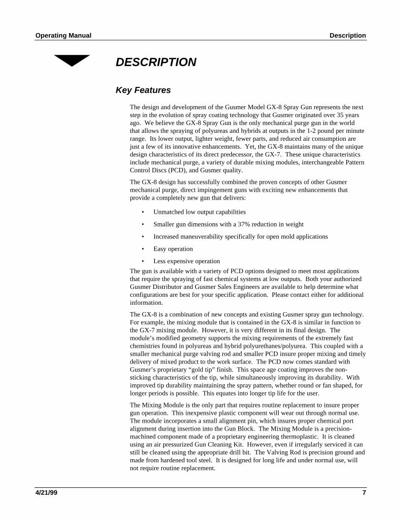
In keeping with the need to gain a complete and thorough understanding of theequipment, please take time to become familiar with the major components of the GX-8Gun (Figure 2) and its Centerline Components (Figure 3). This will be helpful laterwhen these items are covered in the manual.
Safety Stop
AdjustmentAir Cap Air
Valve
Piston Rod
Jam Nut
Valving Rod
Trigger
Manual Valves
Gun Block
Assembly
Air Cap
Coupling Block
Figure 2. Major Components
NOTE:Both Round and Fan MixingModules are available. The
Round Module provides around spray pattern and is
identified by a groove in itscylindrical body. The Fan
Module provides a fan spraypattern and is identified by its
smooth cylindrical body.
Figure 3. Centerline Components
Model GX-8 Spray Gun
10 32943-1, Issue 1
Equipment Supplied
The Standard Tool Kit includes the following tools for use in servicing the GX-8.
Figure 4. Standard Tool Kit
1. 10” Adjustable Wrench (P/N 909A)
2. 6” Adjustable Wrench (P/N 0908)
3. 3/8” x 5/16” Open End Wrench(P/N 1982A)
4. 1/2” Combination Wrench (P/N 1986)
5. 5/16” Spintite (P/N 0904A)
6. Retaining Ring 45°°°° Pliers (P/N 32982)
7. 6” Pliers (P/N 0906)
8. 9/64” Ball Point Hex Key(P/N 0902-9/64)
9. 5/32” Hex Key (P/N 0902-5/32)
10. 3/16” Hex Key (P/N 0902-3/16)
11. 5/64” Hex Key (P/N 0902-5/64)
12. Check Valve Removal/Cleaning Tool(P/N 1948)
13. #80 Clean Out Drill (.0135 Dia.)(P/N 0941-45)
14. #68 Clean Out Drill (.031 Dia.)(P/N 0941-22)
15. #60 Clean Out Drill (.040 Dia.)(P/N 0941-29)
16. 1/8” Dia. Clean Out Drill(P/N 0927-1/8)
17. 21/64” Dia. Clean Out Drill(P/N 0927-21/64)
18. Pin Vise W/Collets (P/N 6902A)
19. Brush (P/N 1945)
20. Flush Can (P/N 0919A)
21. Lubriplate Grease(P/N 0553-2) Not Shown
Operating Manual Description
4/21/99 11
Gun Service Kits
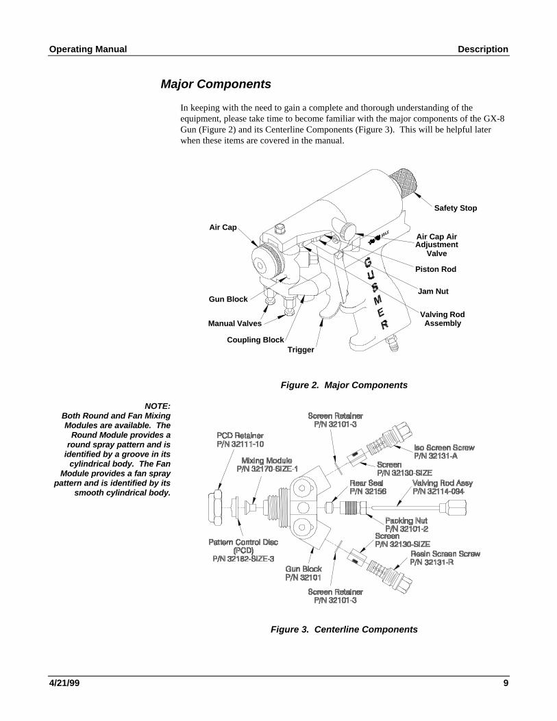
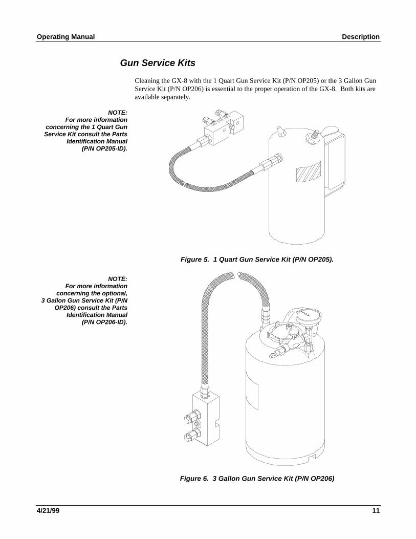
Cleaning the GX-8 with the 1 Quart Gun Service Kit (P/N OP205) or the 3 Gallon GunService Kit (P/N OP206) is essential to the proper operation of the GX-8. Both kits areavailable separately.
NOTE:For more information
concerning the 1 Quart GunService Kit consult the Parts
Identification Manual(P/N OP205-ID).
Figure 5. 1 Quart Gun Service Kit (P/N OP205).
NOTE:For more information
concerning the optional,3 Gallon Gun Service Kit (P/N
OP206) consult the PartsIdentification Manual
(P/N OP206-ID).
Figure 6. 3 Gallon Gun Service Kit (P/N OP206)
Model GX-8 Spray Gun
12 32943-1, Issue 1
OPERATION
WARNING: NEVER POINT THE GUN AT OR NEAR OTHER PERSONNEL OR PLACE ANY PART OF
THE BODY IN THE PATH OF THE MATERIAL SPRAY AND DO NOT AT ANY TIME LOOK INTO THE
DISPENSING END OF THE GUN. WHEN THE GUN IS NOT BEING USED, ALWAYS SET THE REAR STOP
TO THE SAFETY OR SERVICE POSITION, AND CLOSE BOTH MANUAL VALVES. DO THIS TO AVOID
THE POSSIBILITY OF PROPERTY DAMAGE OR BODILY INJURY FROM THE ACCIDENTAL OPERATION
OF THE GUN.
Safety Position of Gun
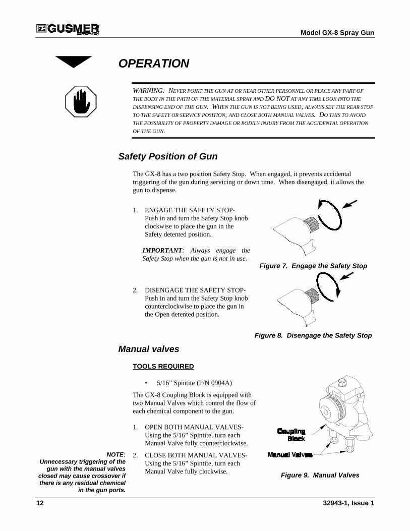
The GX-8 has a two position Safety Stop. When engaged, it prevents accidentaltriggering of the gun during servicing or down time. When disengaged, it allows thegun to dispense.
1. ENGAGE THE SAFETY STOP-Push in and turn the Safety Stop knobclockwise to place the gun in theSafety detented position.
IMPORTANT: Always engage theSafety Stop when the gun is not in use.
Figure 7. Engage the Safety Stop
2. DISENGAGE THE SAFETY STOP-Push in and turn the Safety Stop knobcounterclockwise to place the gun inthe Open detented position.
Figure 8. Disengage the Safety Stop
Manual valves
TOOLS REQUIRED
• 5/16” Spintite (P/N 0904A)
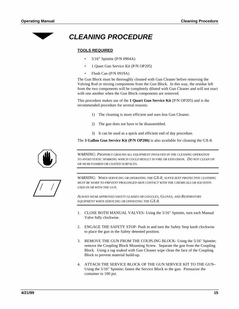
The GX-8 Coupling Block is equipped withtwo Manual Valves which control the flow ofeach chemical component to the gun.
1. OPEN BOTH MANUAL VALVES-Using the 5/16” Spintite, turn eachManual Valve fully counterclockwise.
NOTE:Unnecessary triggering of the
gun with the manual valvesclosed may cause crossover ifthere is any residual chemical
in the gun ports.
2. CLOSE BOTH MANUAL VALVES-Using the 5/16” Spintite, turn eachManual Valve fully clockwise. Figure 9. Manual Valves
Operating Manual Operation
4/21/99 13
IMPORTANT: To avoid accidental gun operation determine that the coupling blockmanual valves have been closed before attempting to service the gun, or any timethe gun is not in use.
Air Line Configuration
TOOLS REQUIRED
• 3/16” Hex Key (P/N 0902-3/16)
• 6” Adjustable Wrench (P/N 0908)
The GX-8 air line connection can be configured in two different ways. The standardconfiguration has the air connection at the base of the handle. The optionalconfiguration has the air connection at the rear of the gun. To change to the optionalconfiguration proceed as follows:
1. REMOVE THE 4“ LONG PIPE NIPPLE- Using the 6” Adjustable Wrench, removethe 4“ long pipe nipple from the base of the Gun.
2. REMOVE THE 1/8” PIPE PLUG- Using the 3/16” Hex Key, remove the 1/8” pipeplug from the rear of the gun.
3. INSTALL THE 1/8” PIPE PLUG- Using the 3/16” Hex Key, install the 1/8” pipeplug in the location previously occupied by the 4“ long pipe nipple.
4. INSTALL THE (OPTIONAL) SUPPLIED BRASS 1/8” NIPPLE- Using the 6”Adjustable Wrench, install the supplied brass 1/8” nipple in the location previouslyoccupied by the 1/8” pipe plug.
Start-Up
TOOLS REQUIRED
• 5/16” Spintite (P/N 0904A)
IMPORTANT: Before attempting the following procedures, make sure the gun isattached to the coupling block and air hoses, the proportioning unit is at the desiredtemperature and pressure, and the system is ready for operation.
1. ADJUST THE AIR VALVE AIR ADJUSTMENT CAP CONTROL- The Knurledknob on the Air Cylinder controls the amount of air that passes over the PCD. Thisflow of air helps keep the PCD free of sprayed chemical. Too much air canadversely effect spray pattern shape and create undesirable amounts of over-spray.However, the airflow can be used to modify the spray pattern. Experiment todetermine what works best for the application.Turn the knob Counter clockwise to open the valve and clockwise to close it.
NOTE:If the GX-8 is shipped from the
factory without the MixingModule and PCD installed the
Valving Rod will requireadjustment. See the Valving
Rod Adjustment section of themanual.
2. OPEN BOTH MANUAL VALVES- Using the 5/16” Spintite, turn each valve fullycounterclockwise.
3. DISENGAGE THE SAFETY STOP- Push in and turn the Safety Stop knobcounterclockwise to place the gun in the Open detented position.
4. TEST SPRAY OFF TARGET
Model GX-8 Spray Gun
14 32943-1, Issue 1
Shutdown
TOOLS REQUIRED
• 5/16” Spintite (P/N 0904A)
IMPORTANT: Follow this procedure whenever the gun is out of service for anylength of time. For mid/end of day, service see the Cleaning Procedure section ofthis manual.
1. ENGAGE THE SAFETY STOP- Push in and turn the Safety Stop knob clockwiseto place the gun in the Safety detented position.
2. CLOSE BOTH MANUAL VALVES- Using the 5/16” Spintite, turn each valvefully clockwise.
3. CLEAN AS REQUIRED- See the Cleaning Procedure section of the manual.NOTE:Disassembling the gun daily
for cleaning is notrecommended if it has been
operating properly. However,experience will determine
whether disassembly isnecessary
IMPORTANT: As an additional safety precaution, the GX-8 air line has quickdisconnect air coupling. Disconnect the air line when transporting the gun with thechemical hoses connected
Operating Manual Cleaning Procedure
4/21/99 15
CLEANING PROCEDURE
TOOLS REQUIRED
• 5/16” Spintite (P/N 0904A)
• 1 Quart Gun Service Kit (P/N OP205)
• Flush Can (P/N 0919A)
The Gun Block must be thoroughly cleaned with Gun Cleaner before removing theValving Rod or mixing components from the Gun Block. In this way, the residue leftfrom the two components will be completely diluted with Gun Cleaner and will not reactwith one another when the Gun Block components are removed.
This procedure makes use of the 1 Quart Gun Service Kit (P/N OP205) and is therecommended procedure for several reasons:
1) The cleaning is more efficient and uses less Gun Cleaner.
2) The gun does not have to be disassembled.
3) It can be used as a quick and efficient end of day procedure.
The 3 Gallon Gun Service Kit (P/N OP206) is also available for cleaning the GX-8.
WARNING: PROPERLY GROUND ALL EQUIPMENT INVOLVED IN THE CLEANING OPERATION
TO AVOID STATIC SPARKING WHICH COULD RESULT IN FIRE OR EXPLOSION. DO NOT CLEAN ON
OR NEAR FOAMED OR COATED SURFACES.
WARNING: WHEN SERVICING OR OPERATING THE GX-8, SUFFICIENT PROTECTIVE CLOTHING
MUST BE WORN TO PREVENT PROLONGED SKIN CONTACT WITH THE CHEMICALS OR SOLVENTS
USED IN OR WITH THE GUN.
ALWAYS WEAR APPROVED SAFETY GLASSES OR GOGGLES, GLOVES, AND RESPIRATORY
EQUIPMENT WHEN SERVICING OR OPERATING THE GX-8.
1. CLOSE BOTH MANUAL VALVES- Using the 5/16” Spintite, turn each ManualValve fully clockwise.
2. ENGAGE THE SAFETY STOP- Push in and turn the Safety Stop knob clockwiseto place the gun in the Safety detented position.
3. REMOVE THE GUN FROM THE COUPLING BLOCK- Using the 5/16" Spintite;remove the Coupling Block Mounting Screw. Separate the gun from the CouplingBlock. Using a rag soaked with Gun Cleaner wipe clean the face of the CouplingBlock to prevent material build-up.
4. ATTACH THE SERVICE BLOCK OF THE GUN SERVICE KIT TO THE GUN–Using the 5/16” Spintite; fasten the Service Block to the gun. Pressurize thecontainer to 100 psi.
Model GX-8 Spray Gun
16 32943-1, Issue 1
5. CLEAN THE GUNNOTE:
Opening one manual valve at atime will allow flushing of
individual chemicals. This isuseful when flushing high
viscosity materials and insuresmaximum effectiveness in
purging the gun of chemical.
a) Open either one of the Manual Valves on the Service Block
b) Disengage the Safety Stop by pushing in and turning the Safety StopKnob counterclockwise to place the gun in the Open detented position.
c) Trigger the Gun Service Kit and the Gun simultaneously catching theGun Cleaner in an appropriate container.(A fine, unobstructed mist of cleaner should exit the Tip.)
d) Release both triggers and close the Manual Valves on the ServiceBlock.
e) Repeat the Procedure for the other side of the Gun.
6. REMOVE THE SERVICE BLOCK OF THE GUN SERVICE KIT FROM THEGUN– Using the 5/16” Spintite; disconnect the Service Block from the gun.
7. CLEAN SCREENS AND SCREEN SCREW- Using the Flush Can, flush out theScreens and the Screen Screw Cavities completely. See the Screen Screw ServiceProcedure section of this manual
Important: At this time it is a good idea to inspect the Air Cap, PCD, Module, andGun Block for build up of material and clean them as required.
Operating Manual Servicing Procedures
4/21/99 17
SERVICING PROCEDURES
Screen Screw Removal And Service Procedure
TOOLS REQUIRED
• 3/8” x 5/16” Open End Wrench (P/N 1982A)
• 1/8” Dia. (P/N 0927-1/8) Clean Out Drill
• 21/64” Dia. (P/N 0927-21/64) Clean Out Drill
• Pin Vise W/Collets (P/N 6902A)
• Flush Can (P/N 0919A)
WARNING: BE SURE TO CLEAN THE “CENTER LINE COMPONENTS” USING THE GUN SERVICE
KIT PRIOR TO REMOVAL FOR SERVICING AS THEY ARE EXPOSED TO THE CHEMICAL. SEE THE
CLEANING PROCEDURES SECTION OF THIS MANUAL.
1. REMOVE THE SCREEN SCREW ASSEMBLY- Using the 3/8” x 5/16” Open EndWrench, unthread the Screen Screw from the Gun Block. Remove the ScreenScrew retainer, the small ring-like part at the bottom of the screen, before removingthe screen. Remove the Retainer by hand. Now, slide off the Screen. If there aresolid particles attached to the Screen, attempt to soak the screen in Gun CleaningSolvent. However, if the screen is especially dirty and clogged, it is better to replaceit.
2. CLEAN THE SCREEN SCREW CAVITY- Inspect the cavity, if any particles arevisible remove them with a combination of the Clean Out Drills mentioned aboveand Cleaning Solvent.
WARNING: ANY MATERIAL LEFT IN THE CAVITY ON THE DOWNSTREAM SIDE OF THE SCREEN
WILL GO DIRECTLY INTO THE MODULE AND PROBABLY CLOG IT.
3. REPLACE THE SCREEN SCREW- Using the 3/8” x 5/16” Open End Wrench,replace the Screen Screw. Make sure the screw is tight to insure the integrity of thismetal to metal seal.
4. CLEAN THE GUN- Clean the gun after cleaning the Cavities and Screens. See theCleaning Procedure section of this manual. In this case, flush the gun with themodule removed. This insures that all particles are expelled from the gun block andprevents blockage of the module ports.
Model GX-8 Spray Gun
18 32943-1, Issue 1
Centerline Component Removal
TOOLS REQUIRED
• 10” Adjustable Wrench (P/N 909A)
• 3/8” x 5/16” Open End Wrench (P/N 1982A
• 1/2” Combination Wrench (P/N 1986)
• 5/16” Spintite (P/N 0904A)
• Lubriplate Grease (P/N 0553-2)
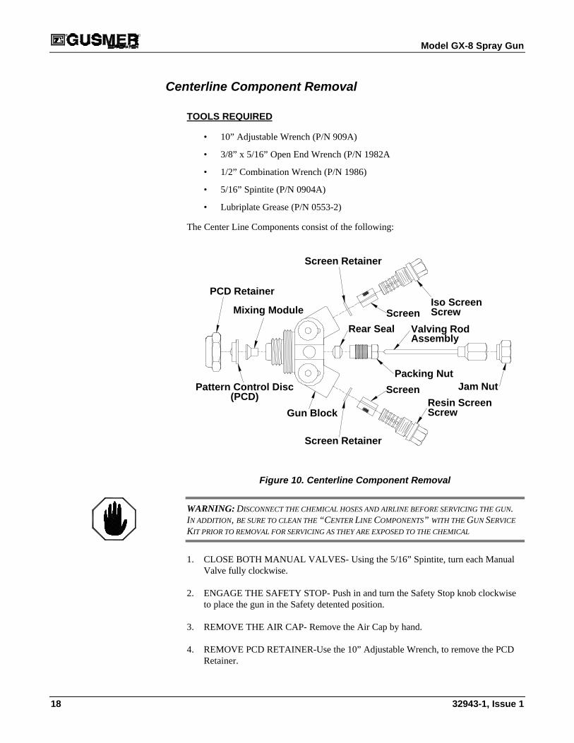
The Center Line Components consist of the following:
Pattern Control Disc
Rear Seal
Gun Block
PCD Retainer
Mixing Module
Packing Nut
Valving Rod
(PCD)
Screen Retainer
Iso ScreenScreen
Screen Retainer
Resin ScreenScreen Jam Nut
Screw
Screw
Assembly
Figure 10. Centerline Component Removal
WARNING: DISCONNECT THE CHEMICAL HOSES AND AIRLINE BEFORE SERVICING THE GUN.IN ADDITION, BE SURE TO CLEAN THE “CENTER LINE COMPONENTS” WITH THE GUN SERVICE
KIT PRIOR TO REMOVAL FOR SERVICING AS THEY ARE EXPOSED TO THE CHEMICAL
1. CLOSE BOTH MANUAL VALVES- Using the 5/16” Spintite, turn each ManualValve fully clockwise.
2. ENGAGE THE SAFETY STOP- Push in and turn the Safety Stop knob clockwiseto place the gun in the Safety detented position.
3. REMOVE THE AIR CAP- Remove the Air Cap by hand.
4. REMOVE PCD RETAINER-Use the 10” Adjustable Wrench, to remove the PCDRetainer.
Operating Manual Servicing Procedures
4/21/99 19
5. REMOVE THE PATTERN CONTROL DISC (PCD)- Lift the PCD off the nose ofthe Gun Block.
Important: To free a PCD that appears to be stuck, set the Safety Stop to the Openposition, then depress and release the gun trigger to unseat it.
6. REMOVE THE MIXING MODULE- Reconnect the air line. Disengage the SafetyStop and depress the trigger and release. The Mixing Module should unseat itselffrom the Gun Block. Lift the Mixing Module off the end of the Valving Rod.Engage the Safety Stop and disconnect the air line.
Important: Do not attempt to dig out the Module using knives or sharp objects.
7. LOOSEN THE PACKING NUT-Using the 5/16” Wrench, back out the PackingNut three or four turns.
NOTE:By removing the Packing Nutentirely the Rear Seal can be
removed and replaced.
8. REMOVE THE GUN BLOCK- Using the 5/16” Spintite, remove the Gun BlockRetaining Screw. Carefully slide the Gun Block away from the Valving Rod andAir Cylinder. If dried chemical has built up on the Gun Block removal may bedifficult. Removing the dried chemical will make removal easier. Be careful not tolose the small “O” Ring seal located in the top if the Gun Block.
9. REMOVE THE VALVING ROD- Using the 3/8” Wrench, on the hex shapedValving Rod Shank and the ½” Wrench on the Jam Nut loosen the Jam Nut byturning it clock wise. (As viewed from the front of the gun.) Continue to back theJam Nut away from the Valving Rod Shank by three or four full turns. Remove theValving Rod by unthreading it from the Piston Assembly.
10. CLEAN ALL COMPONENTS THOROUGHLY BEFORE REASSEMBLY- Usingthe appropriate Brass Brushes, Clean Out Drills, etc. remove residual chemical.Use Cotton Swabs soaked with Gun Cleaner if necessary. When finished, coat thethreads and the mating surfaces of the Gun Block, Gun Block Bracket, and Gunwith Lubriplate Grease. Do not get any grease in the chemical ports located in theGun Block or Mixing Module as this could interfere with chemical flow.
11. INSPECT THE GUN BLOCK- It is important to keep the Gun Block clean and freefrom damage to insure proper operation of the Spray Gun. It has been coated witha proprietary coating to help protect it from damage and make it more difficult forchemical to adhere to it. However, it still requires periodic attention.
Model GX-8 Spray Gun
20 32943-1, Issue 1
Centerline Component Installation
TOOLS REQUIRED
• 10” Adjustable Wrench (P/N 909A)
• 3/8” x 5/16” Open End Wrench (P/N 1982A
• 1/2” Combination Wrench (P/N 1986)
• 5/16” Spintite (P/N 0904A)
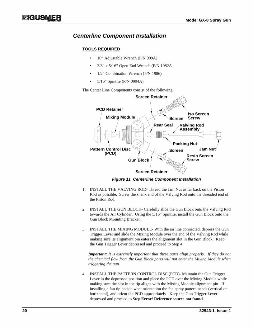
The Center Line Components consist of the following:
Pattern Control Disc
Rear Seal
Gun Block
PCD Retainer
Mixing Module
Packing Nut
Valving Rod
(PCD)
Screen Retainer
Iso ScreenScreen
Screen Retainer
Resin ScreenScreen Jam Nut
Screw
Screw
Assembly
Figure 11. Centerline Component Installation
1. INSTALL THE VALVING ROD- Thread the Jam Nut as far back on the PistonRod as possible. Screw the shank end of the Valving Rod onto the threaded end ofthe Piston Rod.
2. INSTALL THE GUN BLOCK- Carefully slide the Gun Block onto the Valving Rodtowards the Air Cylinder. Using the 5/16” Spintite, install the Gun Block onto theGun Block Mounting Bracket.
3. INSTALL THE MIXING MODULE- With the air line connected, depress the GunTrigger Lever and slide the Mixing Module over the end of the Valving Rod whilemaking sure its alignment pin enters the alignment slot in the Gun Block. Keepthe Gun Trigger Lever depressed and proceed to Step 4.
Important: It is extremely important that these parts align properly. If they do notthe chemical flow from the Gun Block ports will not enter the Mixing Module whentriggering the gun
4. INSTALL THE PATTERN CONTROL DISC (PCD)- Maintain the Gun TriggerLever in the depressed position and place the PCD over the Mixing Module whilemaking sure the slot in the tip aligns with the Mixing Module alignment pin. Ifinstalling a fan tip decide what orientation the fan spray pattern needs (vertical orhorizontal), and orient the PCD appropriately. Keep the Gun Trigger Leverdepressed and proceed to Step Error! Reference source not found..
Operating Manual Servicing Procedures
4/21/99 21
5. INSTALL THE PCD RETAINER- With the Gun Trigger Lever depressed, threadthe PCD Retainer in place by hand. Using the 10” Adjustable Wrench carefullytighten the PCD Retainer until it is “snug” to insure no leaking will occur whenpressurized chemical is introduced in to the gun. Release the Trigger.
WARNING: OVER TIGHTENING, THE PCD RETAINER
WILL CAUSE DAMAGE TO BOTH THE MODULE AND THE
GUN BLOCK.
Important: When installing the Mixing Moduleand/or the PCD a space approximately thethickness of a business card should be betweenthe PCD and the tip of the Gun Block.
Module
PCD
Gun Block
Space6. INSTALL THE AIR CAP- Thread the Air Capin place by hand.
Figure 12. PCD Spacing
7. ADJUST THE VALVING ROD- See the Valving Rod Adjustment section of thismanual
Valving Rod Adjustment
TOOLS REQUIRED
• 3/8” x 5/16” Open End Wrench (P/N 1982A)
• 1/2” Combination Wrench (P/N 1986)
• 5/16” Spintite (P/N 0904A)
The GX-8 Valving Rod should not require adjustment if it was shipped from the factorywith the Mixing Module and Spray Tip installed. The Valving Rod will requireadjusting in the following instances:
• Changing a Piston/Rod assembly/replace O-Ring
• Changing a Valving Rod
• Installing or changing a Spray Tip
• Installing or changing a Mixing Module
WARNING: DISCONNECT THE CHEMICAL HOSES AND AIRLINE BEFORE SERVICING THE GUN.IN ADDITION, BE SURE TO CLEAN THE “CENTER LINE COMPONENTS” WITH THE GUN SERVICE
KIT PRIOR TO REMOVAL FOR SERVICING AS THEY ARE EXPOSED TO THE CHEMICAL
1. ENGAGE THE SAFETY STOP- Push in and turn the Safety Stop knob clockwiseto place the gun in the Safety detented position.
2. CLOSE BOTH MANUAL VALVES- Using the 5/16” Spintite, turn each ManualValve fully clockwise.
Model GX-8 Spray Gun
22 32943-1, Issue 1
3. REMOVE THE GUN FROM THE COUPLING BLOCK- Using the 5/16" Spintite;remove the Coupling Block Mounting Screw. Separate the gun from the CouplingBlock. Using a rag soaked with Gun Cleaner wipe clean the face of the CouplingBlock to prevent material build-up.
4. PRESSURIZE THE AIRCYLINDER- After making sure thatthe Safety Stop is engaged, connectthe air line from the gun to the airsource.
Packing NutJam Nut
Valving RodAssembly
5. LOOSEN REAR PACKING NUT-Using the 5/16” Open-End Wrench,back out the Packing Nut three orfour turns. This will eliminate thecontact pressure between the Seal,located inside the Packing Nut, andthe Valving Rod. With the pressurerelieved, the Valving Rod will movefreely making the adjustmentprocedure easier to perform. Figure 13. Valving Rod Adjustments
6. LOOSEN THE JAM NUT- Using the 3/8” Wrench, on the hex shaped Valving RodShank and the ½” Wrench on the Jam Nut loosen the Jam Nut by turning itclockwise. (As viewed from the front of the gun.) Continue to back the Jam Nutaway from the Valving Rod Shank by three or four full turns. Now move theValving Rod towards the Gun Cylinder by turning the Valving Rod Shank 2 or 3full turns clockwise.
7. ADJUST VALVING ROD CLEARANCE- Slowly turn the Valving Rod counterclockwise, moving it forward towards the Spray Tip until resistance is felt. Go nofurther. The Valving Rod Tip contacting the inside spherical surface of the PCDcauses this resistance.
8. LOCK ADJUSTMENT IN PLACE- While carefully maintaining the position of the3/8” Wrench; tighten the Jam Nut up against the Valving Rod Shank.
9. RETIGHTEN THE PACKING NUT- Using the 3/8” x 5/16” Open End Wrench,retighten the Packing Nut.
10. CHECK THE REAR SAFETY STOP- Disengage the Safety Stop by pushing in andturning the knob counter clockwise. If the knob will not turn, the Valving Rod isadjusted too far forward. Repeat step 6 and 7 making sure not to adjust the ValvingRod past the point where resistance is felt. Once the Safety Stop moves freely,proceed to step 11.
11. CONFIRM REAR SEAL ADJUSTMENT- With the Safety Stop disengaged triggerthe gun. Make sure the Valving Rod moves freely. If it does not, loosen thePacking Nut slightly until it does. Once spraying has started, make sure there is nochemical weeping from the Packing Nut. If there is, retighten it slightly.
Operating Manual Servicing Procedures
4/21/99 23
Air Piston O-Ring and Cup Seal Replacement
TOOLS REQUIRED
• 3/8” x 5/16” Open End Wrench (P/N 1982A)
• 1/2” Combination Wrench (P/N 1986)
• Retaining Ring 45º Pliers (P/N 32982)
• 6” Pliers (P/N 0906)
• 9/64” Ball Point Hex Key (P/N 0902-9/64)
• 5/32” Hex Key (P/N 0902-5/32)
• 3/16” Hex Key (P/N 0902-3/16)
• 5/16” Spintite (P/N 0904A)
WARNING: DISCONNECT THE CHEMICAL HOSES AND AIRLINE BEFORE SERVICING THE GUN. IN
ADDITION, BE SURE TO CLEAN THE “CENTER LINE COMPONENTS” WITH THE GUN SERVICE KIT
PRIOR TO REMOVAL FOR SERVICING AS THEY ARE EXPOSED TO THE CHEMICAL
1. CLOSE BOTH MANUAL VALVES- Using the 5/16” Spintite, turn each ManualValve fully clockwise.
NOTE:If only the End Cap O-Ring
requires replacement see theEnd Cap O-Ring and Cup Seal
Replacement section of thismanual.
2. REMOVE THE GUN FROM THE COUPLING BLOCK- Using the 5/16" Spintite,remove the Coupling Block Mounting Screw. Separate the gun from the CouplingBlock. Using a rag soaked with Gun Cleaner, wipe clean the face of the CouplingBlock to prevent material build-up.
3. CLEAN THE GUN- See the Cleaning Procedure section of this manual.
4. DISCONNECT AIR SUPPLY FROM GUN
5. LOOSEN PACKING NUT- Using the 3/8” x 5/16” Open End Wrench, loosen thePacking Nut.
6. REMOVE GUN BLOCK SCREW- Using the 5/16” Spintite, remove the Gun BlockScrew.
7. REMOVE GUN BLOCK- Pull Gun Block off Valving Rod being careful not tobend the Valving Rod.
8. REMOVE THE VALVING ROD- Using the 3/8” Wrench, on the hex shapedValving Rod Shank and the ½” Wrench on the Jam Nut. Loosen the Jam Nut byturning it clock wise. Continue to back the Jam Nut away from the Valving RodShank by three or four full turns. Remove the Valving Rod by unthreading theValving Rod from the Piston Rod. Remove the Jam Nut from the Piston Rod
9. DISENGAGE THE SAFETY STOP- Push in and turn the Safety Stop knobcounterclockwise to place the gun in the Open detented position.
Model GX-8 Spray Gun
24 32943-1, Issue 1
10. REMOVE SCREW- Using the 9/64” Ball Point Hex Key remove the rear #8 SocketHead Screw that connects the Air Cylinder to the Handle. Remove only this screw.
Piston Assembly
End Cap/Safety Stop Assembly
#8 Socket Head Cap Screw
Retaining Ring
PistonSpring
Figure 14. End Cap/Safety Stop Assembly and Piston Assembly Removal
11. REMOVE THE RETAINING RING- Using the Retaining Ring 45º Pliers removethe Retaining Ring, which maintains the End Cap position in the Air Cylinder.
12. REMOVE THE END CAP/SAFETY STOP ASSEMBLY- Pull the Safety Stop untilit, and the attached End Cap come free from the Air Cylinder. Be sure to retain thePiston Spring located inside of the Air Cylinder for future use.
NOTE:
Removing the End Cap willrequire some force since theO-Ring is tightly compressed 13. INSPECT THE END CAP O-RING- Inspect the O-Ring. If necessary remove it
and install a new O-Ring after lightly coating it with Lubriplate Grease.
14. REMOVE THE PISTON/ROD ASSEMBLY- A second function of the Gun BlockScrew (the screw that holds the Gun Block to the Bracket) is to aid in the removalof the Piston. The Piston is visible from the rear of The Air Cylinder. Thread theGun Block Screw into the hole in the center of the Piston at least four full turns.Using the 6” Pliers take hold of the Gun Block Screw and pull the Piston/RodAssembly out of the Air Cylinder. Inspect the O-Ring for damage and remove it ifrequired. Carefully reinstall the new O-Ring after applying Lubriplate Grease,taking care not to damage it.
15. REPLACE CUP SEAL- Remove and replace the Cup Seal located in the front of theair cylinder if air is escaping around the piston rod during operation. Lubricate thenew cup seal and install it making sure to that the “cup” is facing towards the rearof the air cylinder.
16. REASSEMBLY OF THE PISTON INTO THE AIR CYLINDER - Insert the Pistonand Rod Assembly into the Air cylinder. Be careful not to damage the cup seal inthe front face of the Air Cylinder as the rod passes through it. Remove the GunBlock Mounting Screw from the Piston.
Operating Manual Servicing Procedures
4/21/99 25
17. REASSEMBLE THE END CAP/SAFETY ASSEMBLY/PISTON SPRING- Centerthe Piston Spring over the raised portion of the Piston. Line up the raised portion ofthe End Cap with the inside diameter of the Piston Spring and insert the End Capinto the Air Cylinder. Press the End Cap until it moves past the undercut groove inthe Air Cylinder. This groove is where the Retaining Ring nests. Maintainpressure on the End Cap, making sure the groove remains visible, and install theRetaining Ring using the Retaining Ring 45º Pliers. Reinstall the #8 Socket HeadScrew.
18. REASSEMBLE VALVING ROD ASSEMBLY TO AIR PISTON SHAFT- ThreadJam Nut as far as it will go onto the threaded end of the Piston Shaft. Make surehex end of the nut is facing rear. Thread the Valving Rod as far as it will go ontothe threaded portion of the Piston Rod.
19. RECONNECT THE GUN BLOCK TO GUN BRACKET- Carefully slide the GunBlock onto the Valving Rod towards the Air Cylinder. Using the 5/16” Spintite,install the Gun Block onto the Gun Block Mounting Bracket.
WARNING: INSERT THE RETAINING RING COMPLETELY INTO THE GROOVE SO THAT THE END
CAP WILL REMAIN IN THE AIR CYLINDER WHEN THE GUN HAS AIR PRESSURE APPLIED TO IT.KEEP CLEAR OF THE CAP WHEN FIRST REAPPLYING AIR PRESSURE OR TRIGGERING THE GUN
AFTER REASSEMBLY IN CASE OF IMPROPER RETAINING RING INSTALLATION.
20. READJUST THE VALVING ROD- See the Valving Rod Adjustment section ofthis manual.
End Cap O-Ring and Cup Seal Replacement
TOOLS REQUIRED
• Retaining Ring 45º Pliers (P/N 32982)
• 6” Pliers (P/N 0906)
• 9/64” Ball Point Hex Key (P/N 0902-9/64)
• 5/16” Spintite (P/N 0904A)
• 5/64” Hex Key (P/N 0902-5/64)
WARNING: DISCONNECT THE CHEMICAL HOSES AND AIRLINE BEFORE SERVICING THE GUN. IN
ADDITION, BE SURE TO CLEAN THE “CENTER LINE COMPONENTS” WITH THE GUN SERVICE KIT
PRIOR TO REMOVAL FOR SERVICING AS THEY ARE EXPOSED TO THE CHEMICAL
1. CLOSE BOTH MANUAL VALVES- Using the 5/16” Spintite turn each ManualValve fully clockwise.
2. REMOVE THE GUN FROM THE COUPLING BLOCK- Using the 5/16" Spintiteremove the Coupling Block Mounting Screw. Separate the gun from the CouplingBlock. Using a rag soaked with gun cleaner wipe clean the face of the CouplingBlock to prevent material build-up.
3. DISCONNECT AIR SUPPLY FROM GUN
4. DISENGAGE THE SAFETY STOP- Push in and turn the Safety Stop knobcounterclockwise to place the gun in the Open detented position.
Model GX-8 Spray Gun
26 32943-1, Issue 1
5. REMOVE SCREW- Using the 9/64” Ball Point Hex Key remove the rear #8 SocketHead Screw that connects the Air Cylinder to the Handle. Remove only this screw.
End Cap/Safety Stop Assembly
#8 Socket Head Cap Screw
Retaining Ring
PistonSpring
Figure 15. End Cap/Safety Stop Assembly Removal
6. REMOVE THE RETAINING RING- Using the Retaining Ring 45º Pliers removethe Retaining Ring, which holds the End Cap in place in the Air Cylinder.
7. REMOVE THE END CAP/SAFETY ASSEMBLY- Remove the End Cap and retainthe Piston Spring located inside of the Air Cylinder for future use.
NOTE:Removing the End Cap will
require some force since theO-Ring is tightly compressed 8. INSPECT THE END CAP O-RING- Inspect the O-Ring. If necessary remove it
and install a new O-Ring after lightly coating it with Lubriplate Grease.
9. REMOVE THE SAFETY STOP MECHANISM- Using the 5/64” Hex Key removethe two set screws from the knurled knob. Slide the knob off the shaft and retainthe shaft spring. Pull the shaft out of the End Cap.
10. REPLACE CUP SEAL- Remove and replace the Cup Seal located in the End Cap ifnecessary. Lubricate the new cup seal and install it making sure to that the “cup” isfacing the air cylinder.
11. REINSTALL THE SAFETY STOP MECHANISM- Insert the shaft into the hole inthe End Cap. Slide the shaft spring and knob onto the shaft. Using the 5/64” HexKey reinstall the two set screws in the knurled knob. Make sure the knob is secure.
12. REASSEMBLE THE END CAP/SAFETY STOP ASSEMBLY/PISTON SPRING-Center the Piston Spring over the raised portion of the Piston. Line up the raisedportion of the End Cap with the inside diameter of the Piston Spring and insert theEnd Cap into the Air Cylinder. Press the End Cap until it moves past the undercutgroove in the Air Cylinder. This groove is where the Retaining Ring nests.Maintain force on the End Cap, making sure the groove remains visible, and installthe Retaining Ring using the Retaining Ring 45º Pliers. Reinstall the #8 SocketHead Screw.
WARNING: INSERT THE RETAINING RING COMPLETELY INTO THE GROOVE SO THAT THE END
CAP WILL REMAIN IN THE AIR CYLINDER WHEN THE GUN HAS AIR PRESSURE APPLIED TO IT.KEEP CLEAR OF THE CAP WHEN FIRST REAPPLYING AIR PRESSURE OR TRIGGERING THE GUN
AFTER REASSEMBLY IN CASE OF IMPROPER RETAINING RING INSTALLATION.
Operating Manual Servicing Procedures
4/21/99 27
Trigger Valve O-Ring ReplacementTOOLS REQUIRED
• 5/32” Hex Key (P/N 0902-5/32)
• 3/16” Hex Key (P/N 0902-3/16)
• 6” Adjustable Wrench (P/N 0908)
• 6”Pliers (P/N 0906)
• 3/8” x 5/16” Open End Wrench (P/N 1982A)
• Pin Punch of ¼” diameter or less (Not Included in Tool Kit)
• Ball Peen Hammer (Not Included in Tool Kit)
WARNING: DISCONNECT THE CHEMICAL HOSES AND AIRLINE BEFORE SERVICING THE GUN. IN
ADDITION, BE SURE TO CLEAN THE “CENTER LINE COMPONENTS” WITH THE GUN SERVICE KIT
PRIOR TO REMOVAL FOR SERVICING AS THEY ARE EXPOSED TO THE CHEMICAL
1. CLOSE BOTH MANUAL VALVES- Using the 5/16” Spintite turn each ManualValve fully clockwise.
2. REMOVE THE GUN FROM THE COUPLING BLOCK- Using the 5/16" Spintite,remove the Coupling Block Mounting Screw. Separate the gun from the CouplingBlock. Using a rag soaked with gun cleaner wipe clean the face of the CouplingBlock to prevent material build-up.
3. DISCONNECT AIR SUPPLY FROM GUN
4. REMOVE TRIGGER LEVER- Using the 6” Adjustable Wrench and the 6”Pliersremove the Screw and Locknut that hold the Trigger Lever in place. Remove theTrigger Lever.
5. REMOVE RETAINER NUT- Using the 3/8” end of the 3/8” x 5/16” Open EndWrench, remove the Valve Retainer Nut. This is the hex shaped nut that surroundsthe brass Spool Valve and holds it in place.
Figure 16. Trigger/Air Valve Assembly
Model GX-8 Spray Gun
28 32943-1, Issue 1
NOTE:Refer to Figure 16 for steps 6
through 17.
6. REMOVE THE VALVE SPOOL- In order to replace the O-Rings located on theValve Spool take hold of the end of the Spool and pull it out. Be careful extractingthe Spool as a spring will come out with it. Make sure not to loose this spring as itbelongs in the hole at the end of the Spool. Replace the O-Rings and apply a thincoat of Lubriplate to the O-Rings
7. REMOVE THE VALVE LINER- Attempt to pull the Valve Liner out of the gunhandle through the trigger hole. If successful, proceed to Step11. If the ValveLiner can not be removed, proceed to Step 8.
8. REMOVE REAR 1/8” PLUG- In the rear of the Gun Handle locate the 1/8” PipePlug. This plug seals one of the air flow paths located internally in the Gun Handle.Using the 3/16” Hex Key, remove the Plug.
9. REMOVE THE REAR INTERNAL 1/16” PIPE PLUG- Deeper in the hole that the1/8” Plug was removed from locate the 1/16” Pipe Plug. This Plug seals yet anotherairflow located internally in the Gun Handle. Remove that Plug using the 5/32”Hex Key.
NOTE:Follow Steps 8 through 16 to
replace the O-rings on theValve Liner. If they do not
need replacing go to step 17.
NOTE:If the Gun is configured with
the air supply entering throughthe rear of the Gun Handle, as
opposed to the bottom of theGun Handle, remove the brass1/8” pipe nipple instead of the
1/8” Plug. (See Figure 16)
10. REMOVE THE SPRING SEAT- Looking into the hole from which both Plugs wereremoved the brass surface of the Spring Seat can be seen. Using a Pin Punch of ¼”diameter or less, and a hammer, gently tap the Spring Seat until both it and theValve Liner are pushed out the opposite end of the hole.
11. REMOVE & REPLACE THE O-RINGS- Remove and replace the four O-Rings onthe Liner. Apply a light coat of Lubriplate to the O-Rings.
12. CLEAN THE VALVE HOLE AND REMOVE ANY DEBRIS- After insuring holeis free of any dirt or debris apply a thin coat of Lubriplate to the inside of the hole.
13. REINSTALL THE SPRING SEAT- Slide the brass Spring Seat back into the GunHandle Air Valve hole tapered end first until it bottoms out in the hole.
14. REINSTALL THE VALVE LINER- Push in the brown Valve Liner as far as it willgo. Since there is interference between the O-rings on the Valve Liner and theinside diameter of the hole a fair amount of resistance will be encountered. Oncethe Liner has been pushed in far enough two or three internal threads will bevisible. These threads will allow engagement of the Valve Retainer Nut whichwhen screwed in, will align the Valve Liner and Spool to their proper depth.
15. REINSTALL THE 1/16” PLUG- Using the 5/32” Hex Key screw the 1/16” Pipeplug back in place. Apply a small amount of pipe thread sealant to the threads priorto insertion. This will help seal the threads and prevent air leaks.
16. REINSTALL THE 1/8” PLUG- Apply a small amount of pipe thread sealant to thethreads of the Pipe Plug or Hex Nipple. Using the 3/13” Hex Key reinsert the 1/8”Pipe Plug.
NOTE:If the Gun is configured with
the air supply entering throughthe rear of the Gun Handle,reinstall the brass 1/8” pipe
nipple instead of the 1/8” Plug.(See Figure 16)
17. REINSTALL THE VALVE SPOOL- Insert the Valve Spool, with the Valve SpoolSpring in place into the Valve Liner. Screw in the Valve Retainer Nut. Be carefulnot to over tighten it, just tighten until it is “snug”.
18. REASSEMBLE THE TRIGGER LEVER- Reinstall the Trigger Lever using theScrew and Lock Nut. Tighten using the 6” Adjustable Wrench and the 6”Pliers.