36
Keep this Product ID Number and use when contacting Customer Service: OWNER’S MANUAL MODEL N° 90056 COPY

Keep this Product ID Number and use when contacting Customer Service:
OWNER’S MANUALMODEL N° 90056
COPY

2
Save this owner’s manual for future reference and in the event that the manufacturer has to be contacted.
**U.S. and Canada customers ONLY**IF ASSISTANCE IS NEEDED,
DO NOT CONTACT THE STORE!CALL OUR CUSTOMER SERVICE DEPARTMENT at
1 (800) 225-3865HOURS: 7:00 a.m. to 5:00 p.m. Monday through Friday (Mountain Standard Time)
**Call or visit our Web site for Saturday hours**
Lifetime Products, Inc.
**For customers outside the U.S. or Canada, please contact the store for assistance.**
REGISTER YOUR LIFETIME PRODUCT TODAY!
We invite you to read our privacy policy at www.lifetime.com
as NEW product notifi cations and special closeout promotions!
product, your warranty rights will not be diminished. But you will need to provide a sales receipt to verify your product purchase date before warranty service will be provided.
Maintaining your privacy is our long-standing policy at Lifetime. And you can rest as-sured that Lifetime will not sell or provide your personal data to other third parties, or allow them to use your personal data for their own purposes.
INSTRUCTION #1053853 B 11/6/2009
COPY
3
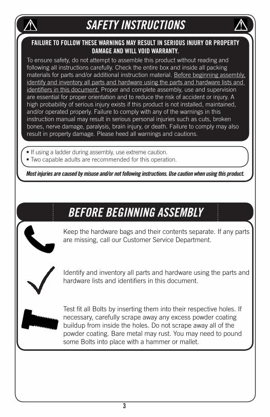
Most injuries are caused by misuse and/or not following instructions. Use caution when using this product.
To ensure safety, do not attempt to assemble this product without reading and following all instructions carefully. Check the entire box and inside all packing materials for parts and/or additional instruction material. Before beginning assembly, identify and inventory all parts and hardware using the parts and hardware lists and identifi ers in this document. Proper and complete assembly, use and supervision are essential for proper orientation and to reduce the risk of accident or injury. A high probability of serious injury exists if this product is not installed, maintained, and/or operated properly. Failure to comply with any of the warnings in this instruction manual may result in serious personal injuries such as cuts, broken bones, nerve damage, paralysis, brain injury, or death. Failure to comply may also result in property damage. Please heed all warnings and cautions.
SAFETY INSTRUCTIONS
BEFORE BEGINNING ASSEMBLYKeep the hardware bags and their contents separate. If any parts are missing, call our Customer Service Department.
Identify and inventory all parts and hardware using the parts and hardware lists and identifi ers in this document.
Test fi t all Bolts by inserting them into their respective holes. If necessary, carefully scrape away any excess powder coating buildup from inside the holes. Do not scrape away all of the powder coating. Bare metal may rust. You may need to pound some Bolts into place with a hammer or mallet.
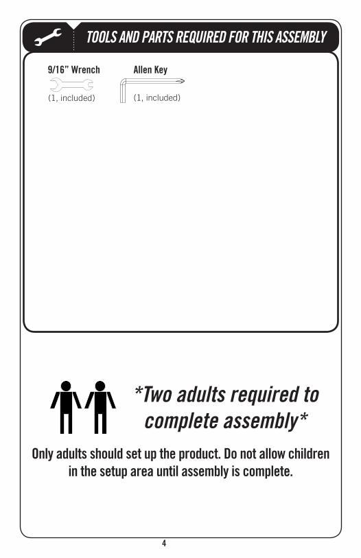
TOOLS AND PARTS REQUIRED FOR THIS ASSEMBLY
*Two adults required to complete assembly*
(1, included) (1, included)

5
This area is located at the top, left-hand corner of the page and indicates which tools and hardware are needed to
on a page.
Note:!
Refer to the following areas throughout the instructions to assist in the assembly process:
bottom, left-hand corner of a step and indicates that special attention is needed to perform a particular part of a step.
the bottom, right-hand corner of a step and indicate that damage to
occur if the caution or warning is not heeded.
ASSEMBLY GUIDES
TOOLS AND HARDWARE REQUIRED FOR THIS PAGE
CAUTION
6
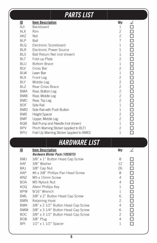
PARTS LISTID Item Description QtyAJI Backboard 1
Rim 2AKZ Net 2
Ball 7Electronic Scoreboard 1Electronic Power Source 1Ball Return Net (not shown) 1
2Bottom Brace 1Cross Bar 2
122
Rear Cross Brace 2BMA 2BMB 2BMC 2BOF Side Rail 1BMD Side Rail with Push Button 1BME Height Spacer 2BMF 2
Ball Pump and Needle (not shown) 12
BPU Fold Up Warning Sticker (applied to BMD) 1
ID Item Description QtyHardware Blister Pack (1055075)
BMJ 3/8” x 1” Button Head Cap Screw 8AAF 3/8” Washer 12BKJ 3/8” Cap Nut 26AAP #6 x 3/8” Phillips Pan Head Screw 8BNZ M5 x 15mm Screw 4BOA M5 Nylock Nut 4
Allen/ Phillips Key 1BPW 9/16” Wrench 1
3/8” x 2” Button Head Cap Screw 6BMN Retaining Hook 2BMK 3/8” x 2 1/2” Button Head Cap Screw 4BMM 3/8” x 3 1/4” Button Head Cap Screw 6BOC 3/8” x 3 1/2” Button Head Cap Screw 2BOB 3/8” Plug 4BPI 1/2” x 1 1/2” Spacer 1
HARDWARE LIST

7
PARTS IDENTIFIERParts shown at 5% of Actual Size
(x1) Backboard
BLU (x1) Bottom Brace
BLV (x2) Cross Bar
(x1)
BLX (x2)
BLY (x2)
BLZ (x2) Rear Cross Brace
BMA (x2)
BMB (x2)
BMC (x2)
(x1) Side Rail
(x2)
BMD (x1) Side Rail with Push Button (Warning Sticker Applied)
BLQ (x1) Electronic Scoreboard
BLR (x1) Electronic Power Source
W
ARNING ADVER
TENCIA AVERTISSEM
ENT
#1034750
BLT (x2)
(Warning Sticker Applied)
Parts shown at 10% of Actual Size
8
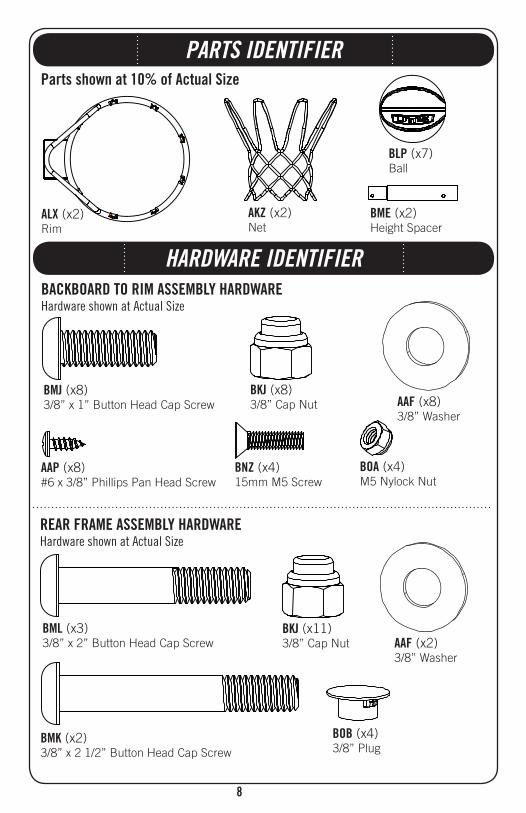
PARTS IDENTIFIERParts shown at 10% of Actual Size
ALX (x2) Rim
AKZ (x2) Net
BLP (x7) Ball
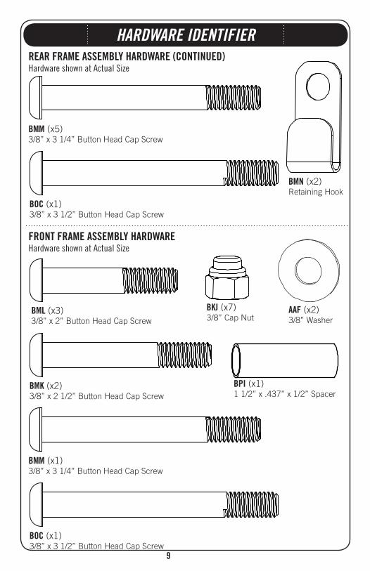
HARDWARE IDENTIFIER
Hardware shown at Actual Size
(x8)3/8” x 1” Button Head Cap Screw
BMK (x2)3/8” x 2 1/2” Button Head Cap Screw
(x8)3/8” Washer
(x8)3/8” Cap Nut
Hardware shown at Actual Size
BML (x3)3/8” x 2” Button Head Cap Screw
(x11)3/8” Cap Nut (x2)
3/8” Washer
BOB (x4)3/8” Plug
AAP (x8)#6 x 3/8” Phillips Pan Head Screw
BME (x2) Height Spacer
BNZ (x4)15mm M5 Screw
BOA (x4)M5 Nylock Nut
9
BMN (x2)Retaining Hook
HARDWARE IDENTIFIER
Hardware shown at Actual Size
BMM (x5)3/8” x 3 1/4” Button Head Cap Screw
Hardware shown at Actual Size
(x2)3/8” Washer
(x7)3/8” Cap Nut
BML (x3)3/8” x 2” Button Head Cap Screw
BMK (x2)3/8” x 2 1/2” Button Head Cap Screw
BOC (x1)3/8” x 3 1/2” Button Head Cap Screw
BOC (x1)3/8” x 3 1/2” Button Head Cap Screw
BMM (x1)3/8” x 3 1/4” Button Head Cap Screw
BPI (x1)1 1/2” x .437” x 1/2” Spacer

10
BACKBOARD TO RIM ASSEMBLY
HARDWARE REQUIRED
PARTS REQUIRED
TOOLS REQUIRED
SEC 1
Parts shown at 10% of Actual Size
Hardware shown at Actual Size
(x1) Backboard
ALX (x2) Rim
AKZ (x2) Net
BLQ (x1) Electronic Scoreboard
Part shown at 5% of Actual Size
(x8)3/8” Cap Nut
(x8)3/8” x 1” Button Head Cap Screw (x8)
3/8” Washer
AAP (x8)#6 x 3/8” Phillips Pan Head Screw
BNZ (x4)15mm M5 Screw BOA (x4)
M5 Nylock Nut
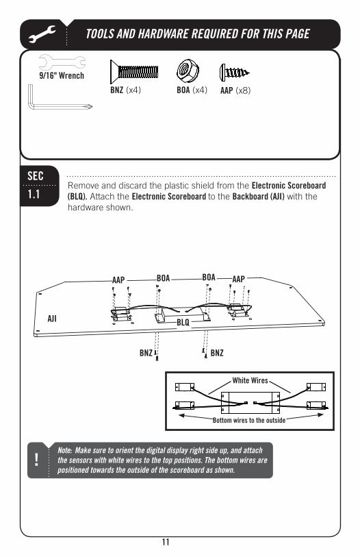
TOOLS AND HARDWARE REQUIRED FOR THIS PAGE
11
Remove and discard the plastic shield from the Electronic Scoreboard (BLQ). Attach the Electronic Scoreboard to the with the hardware shown.
SEC
1.1
Note: Make sure to orient the digital display right side up, and attach the sensors with white wires to the top positions. The bottom wires are positioned towards the outside of the scoreboard as shown.
!
BLQ
AAP (x8)
AAPAAP
BNZ (x4) BOA (x4)
BNZ BNZ
BOA BOA
Bottom wires to the outside
TOOLS AND HARDWARE REQUIRED FOR THIS PAGE
12
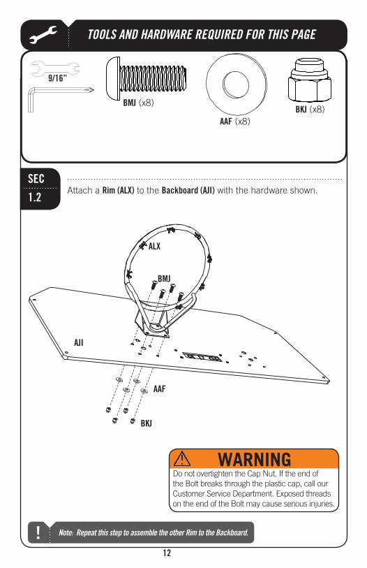
Attach a Rim (ALX) to the with the hardware shown.SEC
1.2
9/16”
WARNINGDo not overtighten the Cap Nut. If the end of the Bolt breaks through the plastic cap, call our Customer Service Department. Exposed threads on the end of the Bolt may cause serious injuries.
Note: Repeat this step to assemble the other Rim to the Backboard.!
ALX
(x8) (x8)
(x8)
TOOLS AND HARDWARE REQUIRED FOR THIS PAGE
13
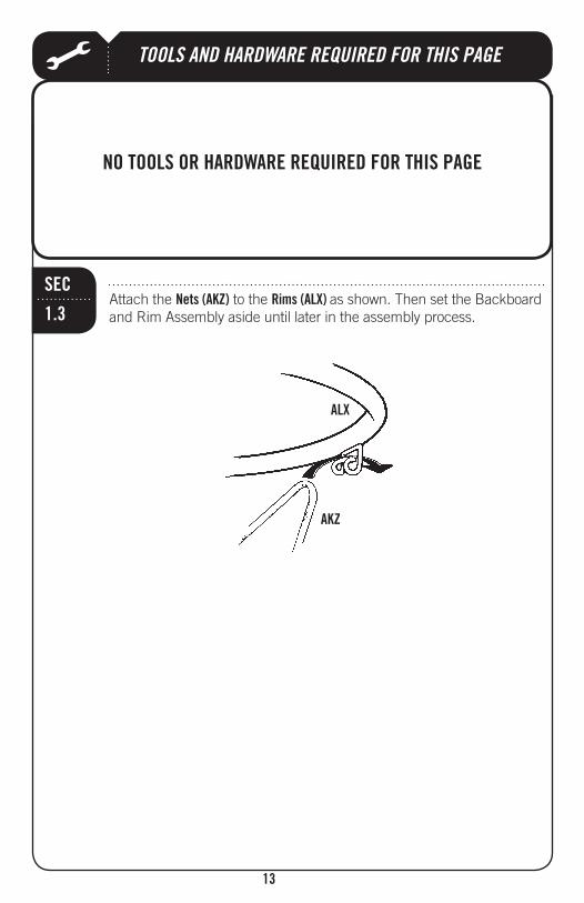
Attach the Nets (AKZ) to the Rims (ALX) as shown. Then set the Backboard and Rim Assembly aside until later in the assembly process.
SEC
1.3
ALX
AKZ
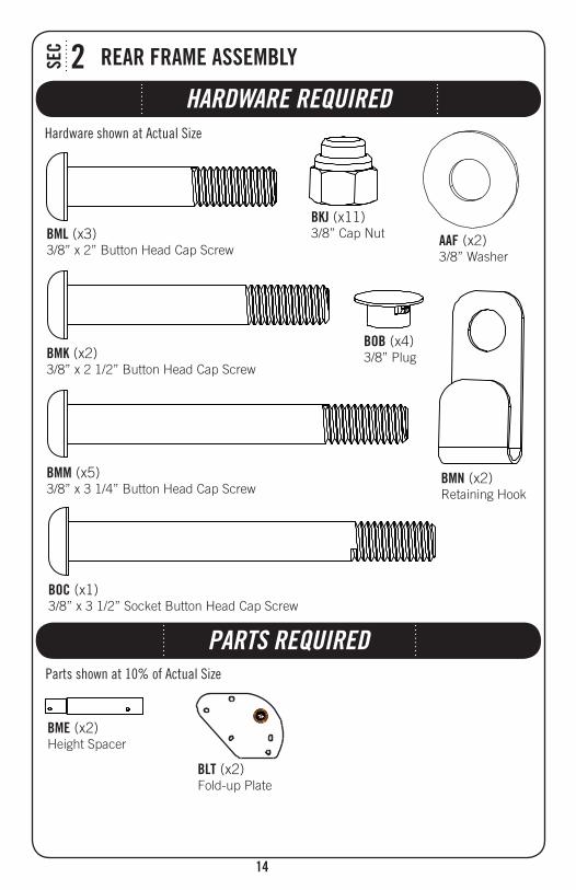
HARDWARE REQUIRED
SEC 2
Hardware shown at Actual Size
(x11)3/8” Cap Nut
BMK (x2)3/8” x 2 1/2” Button Head Cap Screw
BML (x3)3/8” x 2” Button Head Cap Screw
BMM (x5)3/8” x 3 1/4” Button Head Cap Screw
BMN (x2)Retaining Hook
(x2)3/8” Washer
BOB (x4)3/8” Plug
Parts shown at 10% of Actual Size
BME (x2) Height Spacer
W
ARNING ADVER
TENCIA AVERTISSEM
ENT
#1034750
BLT (x2)
PARTS REQUIRED
BOC (x1)3/8” x 3 1/2” Socket Button Head Cap Screw
15
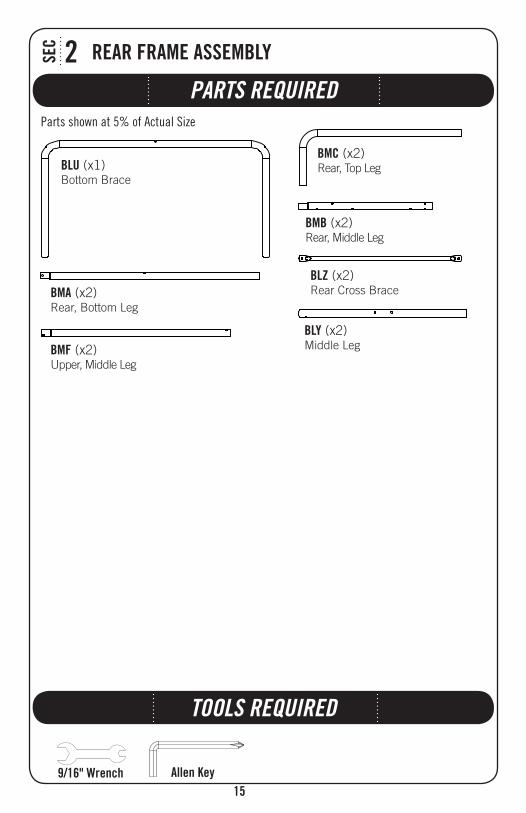
TOOLS REQUIRED
PARTS REQUIRED
SEC 2
Parts shown at 5% of Actual Size
BLU (x1) Bottom Brace
BLY (x2)
BLZ (x2) Rear Cross BraceBMA (x2)
BMB (x2)
BMC (x2)
(x2)
TOOLS AND HARDWARE REQUIRED FOR THIS PAGE
16
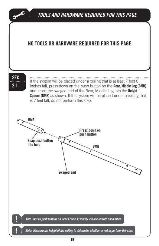
SEC
2.1If the system will be placed under a ceiling that is at least 7 feet 6 inches tall, press down on the push button on the Rear, Middle Leg (BMB)
Height Spacer (BME) as shown. If the system will be placed under a ceiling that is 7 feet tall, do not perform this step.
Note: Measure the height of the ceiling to determine whether or not to perform this step.!
BMB
BME
Snap push button into hole
Press down on push button
Note: Not all push buttons on Rear Frame Assembly will line up with each other. !
Swaged end

TOOLS AND HARDWARE REQUIRED FOR THIS PAGE
17
Press down on push button
Press down on the push button on the Height Spacer (BME) (or the Rear, Middle Leg (BMB) if step 2.2 was not performed) and insert the swaged
Rear, Top Leg (BMC) until the push button snaps into the hole indicated.
SEC
2.2
BMC
Note: Repeat steps 2.1 through 2.3 to assemble the other Rear Leg Assembly. !
BME
BMB
Snap push button into hole
TOOLS AND HARDWARE REQUIRED FOR THIS PAGE
18
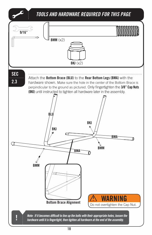
Attach the Bottom Brace (BLU) to the Rear Bottom Legs (BMA) with the hardware shown. Make sure the hole in the center of the Bottom Brace is perpindicular to the ground as pictured. Only fingertighten the 3/8” Cap Nuts
until instructed to tighten all hardware later in the assembly.
SEC
2.3
(x2)
BMM (x2)
9/16”
Do not overtighten the Cap Nut.
Note: If it becomes difficult to line up the bolts with their appropriate holes, loosen the hardware until it is fingertight, then tighten all hardware at the end of the assembly.!
BLU
BMM
BMMBMA
BMA
Bottom Brace Alignment
TOOLS AND HARDWARE REQUIRED FOR THIS PAGE
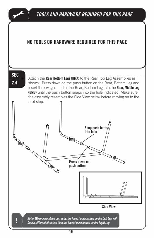
19
Note: When assembled correctly, the lowest push button on the Left Leg will face a different direction than the lowest push button on the Right Leg.!
Attach the Rear Bottom Legs (BMA) and
Rear, Middle Leg (BMB) until the push button snaps into the hole indicated. Make sure
next step.
BMB
Snap push button into hole
Press down on push button
SEC
BMA
BMA
BMB
Side View
TOOLS AND HARDWARE REQUIRED FOR THIS PAGE
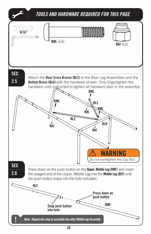
20
Attach the Rear Cross Braces (BLZ)Bottom Brace (BLU) with the hardware shown. Only fingertighten the hardware until instructed to tighten all hardware later in the assembly.
SEC
2.5
(x3)BML (x3)
BML
BML
BML
BLZ
BLZ
BLU
9/16”
Do not overtighten the Cap Nut.
Press down on the push button on the and insert Middle Leg (BLY) until
the push button snaps into the hole indicated.
SEC
2.6
BLY
Note: Repeat this step to assemble the other Middle Leg Assembly.!
Snap push button into hole
Press down on push button
TOOLS AND HARDWARE REQUIRED FOR THIS PAGE
21
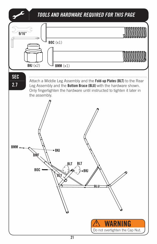
to the Rear Bottom Brace (BLU) with the hardware shown.
Only fingertighten the hardware until instructed to tighten it later in the assembly.
SEC
2.7
BOC (x1)
9/16”
(x2)
BLU
BLT BLT
BMM
BOC
Do not overtighten the Cap Nut.
BMM (x1)
BLY
TOOLS AND HARDWARE REQUIRED FOR THIS PAGE
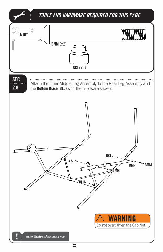
22
the Bottom Brace (BLU) with the hardware shown.
SEC
2.8
9/16”
(x2)
BLU
BMMBMM
Do not overtighten the Cap Nut.
BMM (x2)
BLY
Note: Tighten all hardware now.!
TOOLS AND HARDWARE REQUIRED FOR THIS PAGE
23
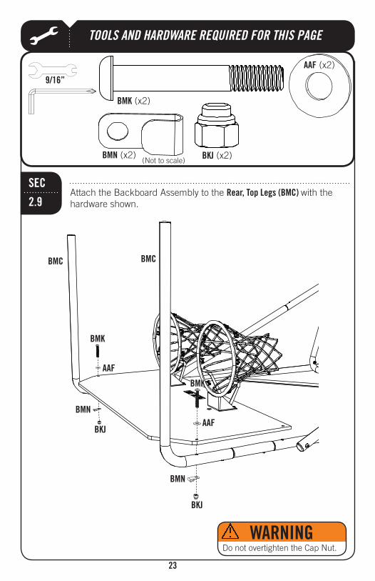
Attach the Backboard Assembly to the Rear, Top Legs (BMC) with the hardware shown.
SEC
2.9
BMC BMC
BMK
BMK (x2)
(x2)BMN (x2)
9/16”
(Not to scale)
BMK
(x2)
BMN
Do not overtighten the Cap Nut.
BMN
TOOLS AND HARDWARE REQUIRED FOR THIS PAGE
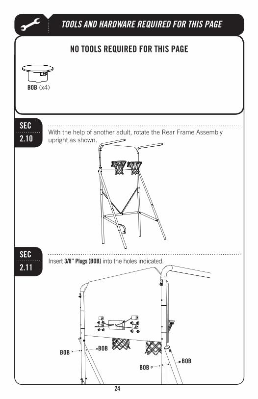
With the help of another adult, rotate the Rear Frame Assembly upright as shown.
SEC
2.10
Insert 3/8” Plugs (BOB) into the holes indicated. SEC
2.11
BOB (x4)
BOBBOB
BOBBOB

25
HARDWARE REQUIRED
SEC 3
Hardware shown at Actual Size
(x7)3/8” Cap Nut
BMK (x2)3/8” x 2 1/2” Button Head Cap Screw
BML (x3)3/8” x 2” Button Head Cap Screw (x2)
3/8” Washer
TOOLS REQUIRED
PARTS REQUIREDParts shown at 5% of Actual Size
BLV (x2) Cross Bar
(x1)
BLX (x2)
BMD (x1) Side Rail with Push Button
BLR (x1) Electronic Power Source
Part shown at 10% of Actual Size
BMM (x1)3/8” x 3 1/4” Button Head Cap Screw
BOC (x1)3/8” x 3 1/2” Socket Button Head Cap Screw
(x1) Side Rail
BPI (x1)1 1/2” x 1/2” Spacer

TOOLS AND HARDWARE REQUIRED FOR THIS PAGE
26
Press down on the push button on the Side Rail with Push Button (BMD) and insert the swaged end of the Side Rail into the until the push button snaps into the hole indicated.
SEC
3.1
Slide the through the sleeve of the Ball Return Net (BLS) as shown. If the Height Spacers (BME) were not attached to the Rear Frame
Ball Return Net.
SEC
3.2
BMD
BLX
Note: Repeat step 3.1 to assemble the other Front Leg Assembly using the Side Rail (BOF) in place of the Side Rail with Push Button.!
Snap push button into hole
Press down on push button
BLS
Lower Slot
Note: Make sure the Warning Label on the Ball Return Net is facing up.!
Lean Bar in sleeve of Ball Return Net

TOOLS AND HARDWARE REQUIRED FOR THIS PAGE
27
Lean Bar until the push buttons snap into the holes indicated. Clip the Straps
together through the loops on both sides of the Ball Return Net near the sleeve.
SEC
3.3
Snap push button into hole
Press down on push button
Double-headed push button
Note: Attach the Front Leg Assembly that has a double-headed push button on the left side of the system as shown..!
Strap

TOOLS AND HARDWARE REQUIRED FOR THIS PAGE
28
Attach the Front Frame Assembly to the Rear Frame Assembly with the hardware shown. Press down on the double headed push button on the
into the holes indicated on the .
SEC
BOC (x1)
9/16”
(x2)
BOC
BMM
Do not overtighten the Cap Nut.
Snap double-headed push button into holes
BMM (x1)
BLT

TOOLS AND HARDWARE REQUIRED FOR THIS PAGE
29
BPI
BPI (x1)
BML (x1) (x1)
9/16”
SEC
3.5Slide the 3/8” x 2” Button Head Cap Screw (BML) through the 1 1/2” x 1/2” Spacer (BPI) . Attach with the hardware shown.
BLS
Do not overtighten the Cap Nut.
BML
TOOLS AND HARDWARE REQUIRED FOR THIS PAGE
30
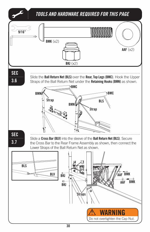
Slide the Ball Return Net (BLS) over the Rear, Top Legs (BMC). Hook the Upper Straps of the Ball Return Net under the Retaining Hooks (BMN) as shown.
SEC
3.6
BLS
BMC
BMCBMN
BMNStrap
Strap
Slide a Cross Bar (BLV) into the sleeve of the Ball Return Net (BLS). Secure the Cross Bar to the Rear Frame Assembly as shown, then connect the
SEC
3.7
BLV
BLS
BMK (x2)
(x2)
9/16”
(x2)
BMK
BMK
Straps
BLS
Do not overtighten the Cap Nut.
TOOLS AND HARDWARE REQUIRED FOR THIS PAGE
31
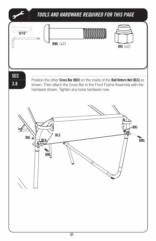
Position the other Cross Bar (BLV) on the inside of the Ball Return Net (BLS) as shown. Then attach the Cross Bar to the Front Frame Assembly with the hardware shown. Tighten any loose hardware now.
SEC
3.8
9/16”
(x2)BML (x2)
BLSBLV
BML
BML

TOOLS AND HARDWARE REQUIRED FOR THIS PAGE
32
Connect the Electronic Power Source (BLR) to the Electronic Scoreboard (BLQ) as shown.
SEC
3.9
PLAY TEST
then
Note: To reset the high score, toggle the Test Switch to the right, then back to the left. The unit must be plugged in to reset scores. Scores over 100 are indicated by a dot ; for example, 04.=104 points.!
Test Switch
Note: This system is intended for indoor use only.!
BLQ
BLR

33
ENHANCE YOUR LIFETIME® PURCHASE BY ADDING ACCESSORIES OR OTHER GREAT PRODUCTS:
Or call: 1-800-424-3865
To purchase accessories or other Lifetime Products, visit us at:
www.lifetime.com

Do not climb on the structure of the Double Shot system.
WARNING
1052685
If the Warning Label is illegible, destroyed or removed, contact Customer Service for a replacement.
The Warning Label is located on the Ball Return Net at the front of the system.
The Pinch Warning stickers are located on the Fold-up Plateson the left side of the system near the bottom.
The System Fold Up Warning sticker is locatedon the Side Rail with Push Button
on the left side of the system near the bottom.
WARNING
1054766
Place one hand here when folding and unfolding the Double Shot system. Fail-ure to do so may result in serious injury or property damage.
W
ARNING ADVERTENCIA AVERTISSE
MEN
T
#1034750

35
NOTES
36
UNAVAILABLE OR OBSOLETE.
material or workmanship for a period of ninety days from the date of original retail purchase. The word “defects” is defi ned as imperfections that impair the use of the product. Defects resulting from misuse, abuse or negligence will void this warranty. This warranty does not cover defects due to improper installation, alteration or accident. This warranty does not cover damage caused by vandalism, rusting, “acts of nature” or any other event beyond the control of the manufacturer.
2. This warranty is nontransferable and is expressly limited to the repair or replacement of defective
Inc. will repair or replace defective parts at no cost to the purchaser. Shipping charges to and from
expenses for removal, installation or replacement of the basketball system or its components are not covered under this warranty.
3. This warranty does not cover scratching or scuffi ng of the product that may result from normal usage. In addition, defects resulting from intentional damage, negligence, unreasonable use or hanging from the net or rim will void this warranty.
cannot be guaranteed. The user assumes all risk of injury resulting from the use of this product. All merchandise is sold on this condition, and no representative of the company may waive or change this policy.
any liability for such use. Institutional or commercial use will void the warranty.
6. This warranty is expressly in lieu of all other warranties, expressed or implied, including warranties
Products, Inc., nor any representative assumes any other liability in connection with this product. This warranty gives you specifi c legal rights, and you may also have other rights which vary from state to state.
**Call or visit our Web site for Saturday hours**
Please include your dated sales receipt and photographs of damaged parts.
WARRANTY INFORMATION


