26
TECHNICAL SPECIFICATION A5LCY-I(F)_(i)-0005 Supercedes: A5LCY-I(F)_(i)-0004 Model Name Models : Indoor Outdoor Heatpump A5WMY10LR A5LCY10FR A5WMY15LR A5LCY15FR

TECHNICAL SPECIFICATION
A5LCY-I(F)_(i)-0005
Supercedes: A5LCY-I(F)_(i)-0004
Model Name Models : Indoor Outdoor
Heatpump A5WMY10LR A5LCY10FR
A5WMY15LR A5LCY15FR

TECHNICAL SPECIFICATION
A5LCY-I(F)_(i)
Note: Installation and maintenance are to be performed only by qualified personnel who are familiar with local codes and regulation, and experienced with this type of equipment
Caution : Sharp edges and coil surfaces are a potential injury hazard. Avoid contact with them
Warning : Moving machinery and electrical power hazard may cause severe personnel injury or death. Disconnect and lock off power before servicing equipment
“Acson” is a registered trademark of Acson International. All rights reserved. © 2011 Acson International. All rights reserved throughout the world.
Bulletin illustrations cover the general appearance of Acson International products at the time of publication. We reserve the right to change design and construction specification at any time without notice
Content Page Nomenclature ---------------------------------------- 1
- Product Line-up 2
Application Information ---------------------------------------- 3
- Operating Range 3
- Refrigeration Circuit 4
Sound Data ---------------------------------------- 5
- Sound Pressure Level 5 Engineering and Physical Data ---------------------------------------- 6
Outline and Dimension ---------------------------------------- 8
Wiring Diagrams ---------------------------------------- 10
Error Code ---------------------------------------- 11
Part List ---------------------------------------- 19

TECHNICAL SPECIFICATION
A5LCY-I(F)_(i)
1
Nomenclature Indoor
A 5 WM Y 10 L R – A C B D D
Outdoor
A 5 LC Y 10 F R – A C D O A
Refrigerant “ ”: R22 4: R407C 5: R410A
Product Type WM: Wall Mounted
Size 10 : 8,700 ~ 9,700 Btu/h 15 : 11,000 ~ 11,900 Btu/h Product series L: L Series
Model “ ”: Cooling Only
R: Heat Pump
Product Specification Variation
D: Fourth Issue
Type of Air Filter B: Bio Filter
Electrical Characteristics A : 50Hz / 1Ph / 220-240V F : 50Hz / 3Ph / 380-415V
Inverter System Type Y: Y Series
Market Region C: Export with CE Marking
Grille D: Grille D
Brand A: Acson
Refrigerant “ ”: R22 4: R407C 5: R410A
Product Type LC: Single Split Condensing Unit
Size 10 : 8,700 ~ 9,700 Btu/h 15 : 11,000 ~ 11,900 Btu/h Product series F: F Series
Model “ ”: Cooling Only
R: Heat Pump
Product Specification Variation
A: First Issue
Compressor D: Daikin
Electrical Characteristics A : 50Hz / 1Ph / 220-240V F : 50Hz / 3Ph / 380-415V
Inverter System Type Y: Y Series
Market Region C: Export with CE Marking
Specifications Variation O: Standard Unit
Brand A: Acson

TECHNICAL SPECIFICATION
A5LCY-I(F)_(i)
2
Product Line Up
Indoor Unit
A5WMY-L Series
Outdoor Unit
A5LCY-F Series
A5WMY
Nom
encl
atur
e Classification
Han
dset
PCB
Air
Pur
ifica
tion
Mar
king
Oth
ers
APG
S02
W_2
_03A
Sara
net F
ilter
Bio
Ant
ibod
y Fi
lter
Tita
nium
Apa
tite
Filt
er
CE
Aut
o R
esta
rt
HEA
T PU
MP 10LR ACBDD X X X X X X X
15LR ACBDD X X X X X X X
A5LCY
Nom
encl
atur
e
Classification
PCB
Ref
riger
ant
Con
trol
FIN
Safe
ty D
evic
es
Com
pres
sor
Mar
king
Oth
ers
2P25
7375
-1
Cap
Tub
e
EXV
Gol
d C
oate
d
Blu
e C
oate
d
Bar
e Fi
n
Ove
rload
Rel
ay
HP
LP
DC
Inve
rter
Sw
ing
C
ompr
esso
r
DC
Inve
rter
Scr
oll
Com
pres
sor
CE
HEA
T PU
MP 10FR ACDOA X X X X X X
15FR ACDOA X X X X X X

TECHNICAL SPECIFICATION
A5LCY-I(F)_(i)
3
Application Information Operating Range
Ensure the operating temperature is in allowable range.
Heatpump

TECHNICAL SPECIFICATION
A5LCY-I(F)_(i)
4
Refrigerant Circuit Diagram
Model: A5WMY10LR – A5LCY10FR A5WMY15LR – A5LCY15FR
70014113878

TECHNICAL SPECIFICATION
A5LCY-I(F)_(i)
5
Sound Data Sound Pressure Level
Model Speed 1/1 Octave A-Weighted Sound Pressure (dBA), ref 20µPa Overall (dBA)
Noise Criteria 125Hz 250Hz 500Hz 1kHz 2kHz 4kHz 8kHz
A5WMY10LR Turbo 43 39 37 37 33 26 13 41 36 High 42 38 37 36 32 24 12 40 35
Medium 37 33 32 30 25 17 13 34 29 Low 32 29 28 24 19 14 13 29 22 Quiet 21 22 20 15 10 7 8 21 -
A5WMY15LR Turbo 41 39 38 38 36 29 15 42 37 High 40 38 38 37 34 27 14 41 36
Medium 36 32 32 30 26 18 11 34 29 Low 33 29 29 25 21 15 11 30 23 Quiet 24 22 21 17 11 7 7 22 -
010102000WMY-L
SOUND PRESSURE LEVEL ARE TESTED ACCORDING TO JIS C 9612 STANDARD. POSITION OF THE MEASUREMENT POINT IS 1.4m BELOW THE UNIT.
TECHNICAL SPECIFICATION
A5LCY-I(F)_(i)
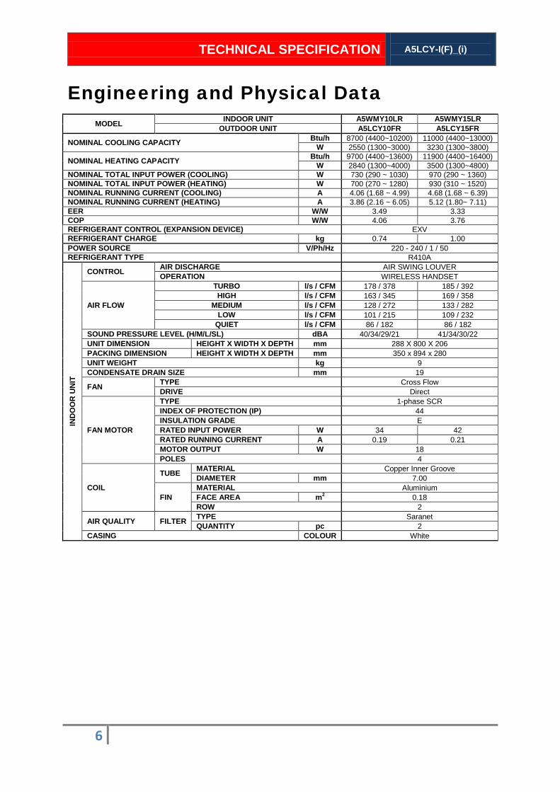
6
MODEL INDOOR UNIT A5WMY10LR A5WMY15LR OUTDOOR UNIT A5LCY10FR A5LCY15FR
NOMINAL COOLING CAPACITY Btu/h 8700 (4400~10200) 11000 (4400~13000) W 2550 (1300~3000) 3230 (1300~3800)
NOMINAL HEATING CAPACITY Btu/h 9700 (4400~13600) 11900 (4400~16400) W 2840 (1300~4000) 3500 (1300~4800)
NOMINAL TOTAL INPUT POWER (COOLING) W 730 (290 ~ 1030) 970 (290 ~ 1360) NOMINAL TOTAL INPUT POWER (HEATING) W 700 (270 ~ 1280) 930 (310 ~ 1520) NOMINAL RUNNING CURRENT (COOLING) A 4.06 (1.68 ~ 4.99) 4.68 (1.68 ~ 6.39) NOMINAL RUNNING CURRENT (HEATING) A 3.86 (2.16 ~ 6.05) 5.12 (1.80~ 7.11) EER W/W 3.49 3.33 COP W/W 4.06 3.76 REFRIGERANT CONTROL (EXPANSION DEVICE) EXV REFRIGERANT CHARGE kg 0.74 1.00 POWER SOURCE V/Ph/Hz 220 - 240 / 1 / 50 REFRIGERANT TYPE R410A
IND
OO
R U
NIT
CONTROL AIR DISCHARGE AIR SWING LOUVER OPERATION WIRELESS HANDSET
AIR FLOW
TURBO l/s / CFM 178 / 378 185 / 392 HIGH l/s / CFM 163 / 345 169 / 358
MEDIUM l/s / CFM 128 / 272 133 / 282 LOW l/s / CFM 101 / 215 109 / 232
QUIET l/s / CFM 86 / 182 86 / 182 SOUND PRESSURE LEVEL (H/M/L/SL) dBA 40/34/29/21 41/34/30/22 UNIT DIMENSION HEIGHT X WIDTH X DEPTH mm 288 X 800 X 206 PACKING DIMENSION HEIGHT X WIDTH X DEPTH mm 350 x 894 x 280 UNIT WEIGHT kg 9 CONDENSATE DRAIN SIZE mm 19
FAN TYPE Cross Flow DRIVE Direct
FAN MOTOR
TYPE 1-phase SCR INDEX OF PROTECTION (IP) 44 INSULATION GRADE E RATED INPUT POWER W 34 42 RATED RUNNING CURRENT A 0.19 0.21 MOTOR OUTPUT W 18 POLES 4
COIL
TUBE MATERIAL Copper Inner Groove DIAMETER mm 7.00
FIN MATERIAL Aluminium FACE AREA m2 0.18 ROW 2
AIR QUALITY FILTER TYPE Saranet QUANTITY pc 2
CASING COLOUR White
Engineering and Physical Data
TECHNICAL SPECIFICATION
A5LCY-I(F)_(i)
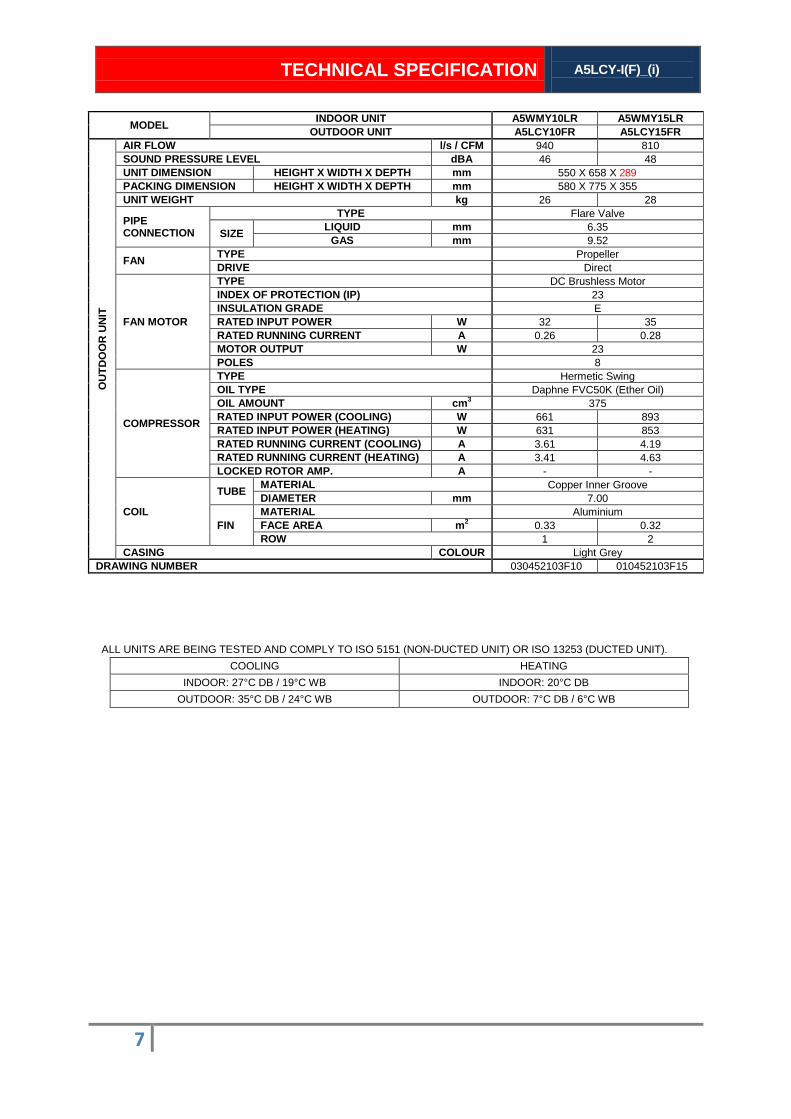
7
MODEL INDOOR UNIT A5WMY10LR A5WMY15LR OUTDOOR UNIT A5LCY10FR A5LCY15FR
OU
TDO
OR
UN
IT
AIR FLOW l/s / CFM 940 810 SOUND PRESSURE LEVEL dBA 46 48 UNIT DIMENSION HEIGHT X WIDTH X DEPTH mm 550 X 658 X 289 PACKING DIMENSION HEIGHT X WIDTH X DEPTH mm 580 X 775 X 355 UNIT WEIGHT kg 26 28
PIPE CONNECTION
TYPE Flare Valve
SIZE LIQUID mm 6.35 GAS mm 9.52
FAN TYPE Propeller DRIVE Direct
FAN MOTOR
TYPE DC Brushless Motor INDEX OF PROTECTION (IP) 23 INSULATION GRADE E RATED INPUT POWER W 32 35 RATED RUNNING CURRENT A 0.26 0.28 MOTOR OUTPUT W 23 POLES 8
COMPRESSOR
TYPE Hermetic Swing OIL TYPE Daphne FVC50K (Ether Oil) OIL AMOUNT cm3 375 RATED INPUT POWER (COOLING) W 661 893 RATED INPUT POWER (HEATING) W 631 853 RATED RUNNING CURRENT (COOLING) A 3.61 4.19 RATED RUNNING CURRENT (HEATING) A 3.41 4.63 LOCKED ROTOR AMP. A - -
COIL
TUBE MATERIAL Copper Inner Groove DIAMETER mm 7.00
FIN MATERIAL Aluminium FACE AREA m2 0.33 0.32 ROW 1 2
CASING COLOUR Light Grey DRAWING NUMBER 030452103F10 010452103F15
ALL UNITS ARE BEING TESTED AND COMPLY TO ISO 5151 (NON-DUCTED UNIT) OR ISO 13253 (DUCTED UNIT).
COOLING HEATING
INDOOR: 27°C DB / 19°C WB INDOOR: 20°C DB
OUTDOOR: 35°C DB / 24°C WB OUTDOOR: 7°C DB / 6°C WB
TECHNICAL SPECIFICATION
A5LCY-I(F)_(i)
8
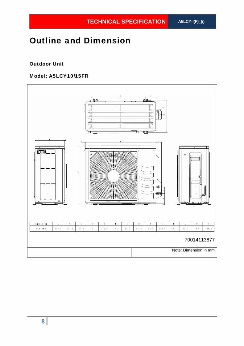
Outdoor Unit
Model: A5LCY10/15FR
Outline and Dimension
70014113877
Note: Dimension in mm

TECHNICAL SPECIFICATION A5LCY-I(F)_(i)
9
Indoor Unit
Model: A5WMY10/15LR
Note: Dimension in mm

TECHNICAL SPECIFICATION
A5LCY-I(F)_(i)
10
Outdoor Unit Indoor Unit
Model: A5LCY10/15FR Model: A5WMY10/15LR
70034113879
Wiring Diagram
TECHNICAL SPECIFICATION
A5LCY-I(F)_(i)
11
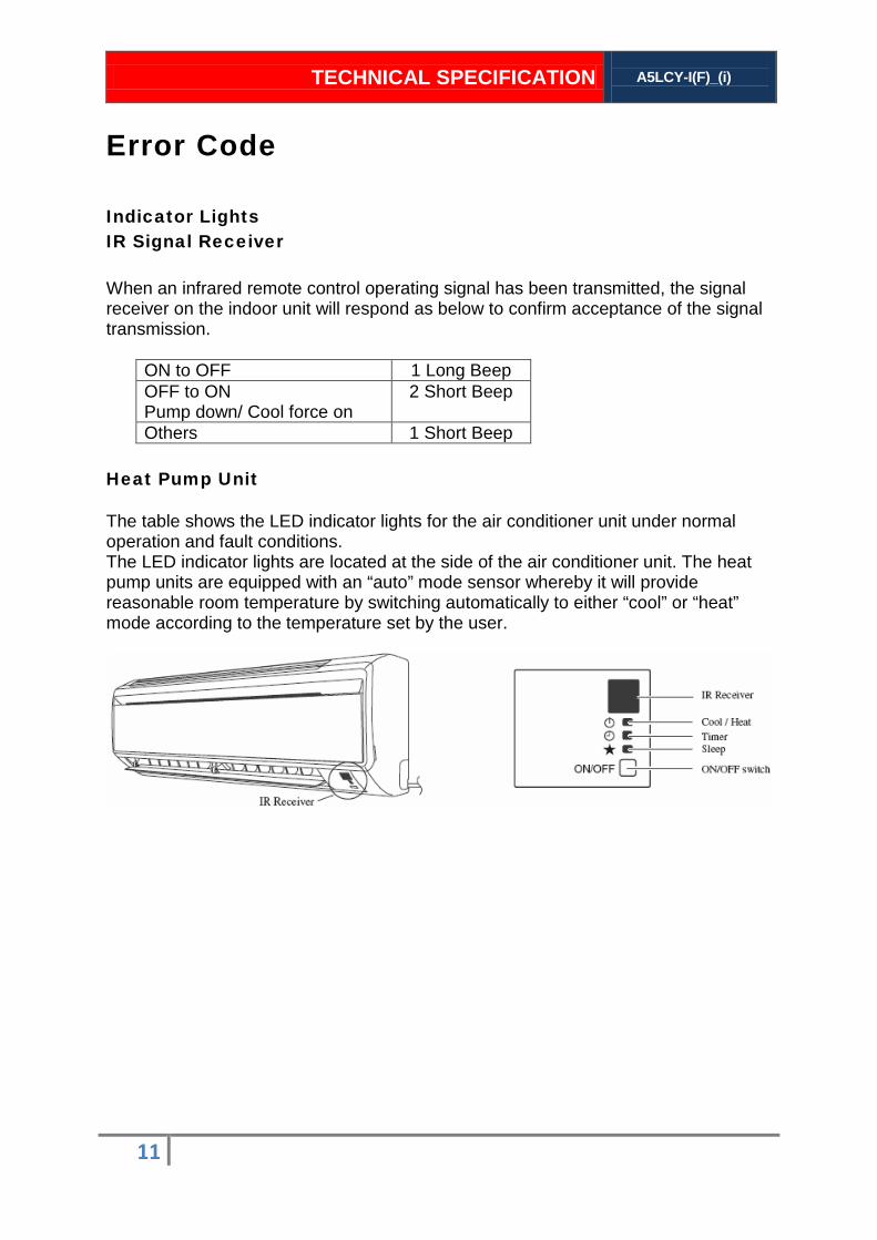
Indicator Lights IR Signal Receiver When an infrared remote control operating signal has been transmitted, the signal receiver on the indoor unit will respond as below to confirm acceptance of the signal transmission.
Heat Pump Unit The table shows the LED indicator lights for the air conditioner unit under normal operation and fault conditions. The LED indicator lights are located at the side of the air conditioner unit. The heat pump units are equipped with an “auto” mode sensor whereby it will provide reasonable room temperature by switching automatically to either “cool” or “heat” mode according to the temperature set by the user.
Error Code
ON to OFF 1 Long Beep OFF to ON Pump down/ Cool force on
2 Short Beep
Others 1 Short Beep

TECHNICAL SPECIFICATION
A5LCY-I(F)_(i)
12
LED Indicator Lights: Normal Operation and Fault Conditions for Heat Pump Unit
Operation / Faulty Indication
Cooling mode
Heating mode
Auto mode in heating operation
Auto mode in cooling operation
Time Off (when unit is on)
Time On (when unit is off)
Sleep mode on
Fan mode on
Dry Mode on
Red
Defrost operation
Error indication
COOL/HEAT
(GREEN/RED)
Green
Red
Red
Green
Green
Green
Green
ON Blinking
SLEEP
(RED)
Green
Green
Green
Green
Red
Red
Green
TIMER
(YELLOW)
COOL/HEAT
(GREEN/RED)
SLEEP
(RED)
ON
Blinking
Green
Green
Green
Green
Red
Red
Green
TIMER
(YELLOW)
Brand A: Acson
TIMER
(YELLOW)

TECHNICAL SPECIFICATION
A5LCY-I(F)_(i)
13
Error Code Diagnosis by Wireless Handset APGS02
Diagnosis Step
1. Hold down TIMER CANCEL button for 5 seconds, a “ ” indication flashes on the temperature display section.
2. Press TIMER CANCEL repeatedly until indoor buzzer produces a long beep. This indicates the error code, refers to Error Codes table and is displayed on the temperature display section.
3. A short beep or two consecutive beeps indicate non-corresponding error codes.
4. To cancel the error code display, hold down TIMER CANCEL button for 5 seconds. Alternatively, the code display will cancel itself if the button is not pressed for 1 minute.
Error Codes Error Description Action
0 Normal No action.
U0 Insufficient gas
1. Check sensor connection. 2. Check stop valve. 3. Check for gas leak. 4. Check the EXV. 5. Check H8.
U2 DC voltage out of range
1. Check the supply voltage. 2. Check the outdoor fan by rotating with hand. 3. Restart the system. 4. Check power supply waveform.
U4 Communication error
1. Check the indoor unit - outdoor unit connection wires. 2. Check the voltage of the signal terminal. 3. Check the indoor fan by rotating with hand. 4. Check the power supply waveform.

TECHNICAL SPECIFICATION
A5LCY-I(F)_(i)
14
Error Codes Error Description Action
U7 Signal transmission error (on outdoor unit PCB)
1. Restart the system.
2. Replace outdoor PCB.
3. Long term monitor on external factor.
UA Installation error 1. Check the indoor and outdoor unit model name.
2. Check the part code on the indoor and outdoor PCB.
UF
Communication Error (indoor and outdoor) piping and wiring
1. Check the wiring and piping between indoor and outdoor units.
2. Check refrigerant level.
3. Check refrigerant line on blockage.
UH Anti-freeze function in other room
1. Check which indoor having error A5.
2. Check the supply voltage.
3. Check the indoor and outdoor model name.
A1 Indoor PCB error 1. Check connector connection.
2. Replace indoor PCB.
A3 Water pump error
1. Check for short circuit.
2. Check connection on drain pump.
3. Restart the system.
4. Check the drain water level.
5. Check float switch connection.
A5 Antifreeze
1. Check the air passage.
2. Check the intake air filter.
3. Check dust accumulation on indoor coil.
4. Check wiring and piping.
5. Check the EXV.
6. Check indoor coil sensor resistance value.
7. Check refrigerant level.
8. Check room sensor resistance value.
A6 Indoor fan motor abnormal
1. Check the indoor fan by rotating with hand.
2. Replace indoor fan motor if not rotating smoothly.
3. Check fan motor voltage.
4. Replace indoor PCB if not at the rated voltage.
5. Check fan capacitor's conductivity (AC Motor).
6. Replace fan capacitor if there's conductivity.
TECHNICAL SPECIFICATION
A5LCY-I(F)_(i)
15
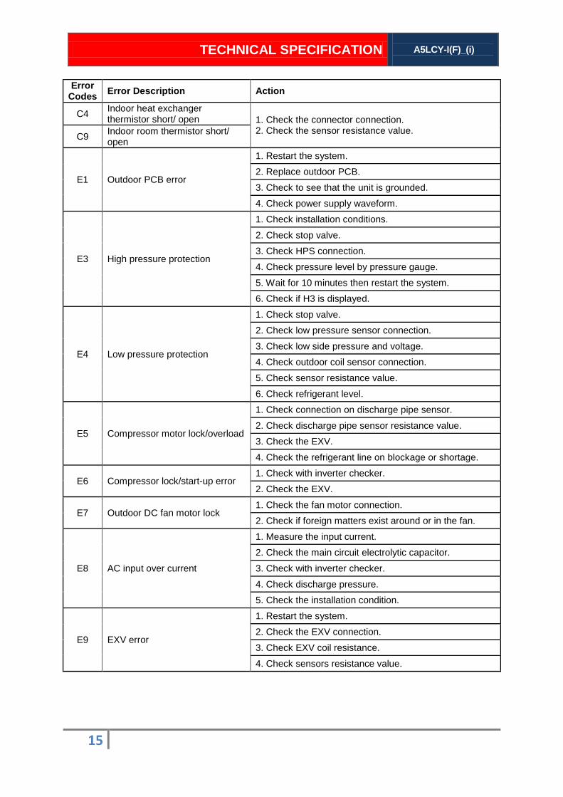
Error Codes Error Description Action
C4 Indoor heat exchanger thermistor short/ open 1. Check the connector connection.
2. Check the sensor resistance value. C9 Indoor room thermistor short/ open
E1 Outdoor PCB error
1. Restart the system.
2. Replace outdoor PCB.
3. Check to see that the unit is grounded.
4. Check power supply waveform.
E3 High pressure protection
1. Check installation conditions.
2. Check stop valve.
3. Check HPS connection.
4. Check pressure level by pressure gauge.
5. Wait for 10 minutes then restart the system.
6. Check if H3 is displayed.
E4 Low pressure protection
1. Check stop valve.
2. Check low pressure sensor connection.
3. Check low side pressure and voltage.
4. Check outdoor coil sensor connection.
5. Check sensor resistance value.
6. Check refrigerant level.
E5 Compressor motor lock/overload
1. Check connection on discharge pipe sensor.
2. Check discharge pipe sensor resistance value.
3. Check the EXV.
4. Check the refrigerant line on blockage or shortage.
E6 Compressor lock/start-up error 1. Check with inverter checker.
2. Check the EXV.
E7 Outdoor DC fan motor lock 1. Check the fan motor connection.
2. Check if foreign matters exist around or in the fan.
E8 AC input over current
1. Measure the input current.
2. Check the main circuit electrolytic capacitor.
3. Check with inverter checker.
4. Check discharge pressure.
5. Check the installation condition.
E9 EXV error
1. Restart the system.
2. Check the EXV connection.
3. Check EXV coil resistance.
4. Check sensors resistance value.
TECHNICAL SPECIFICATION
A5LCY-I(F)_(i)
16
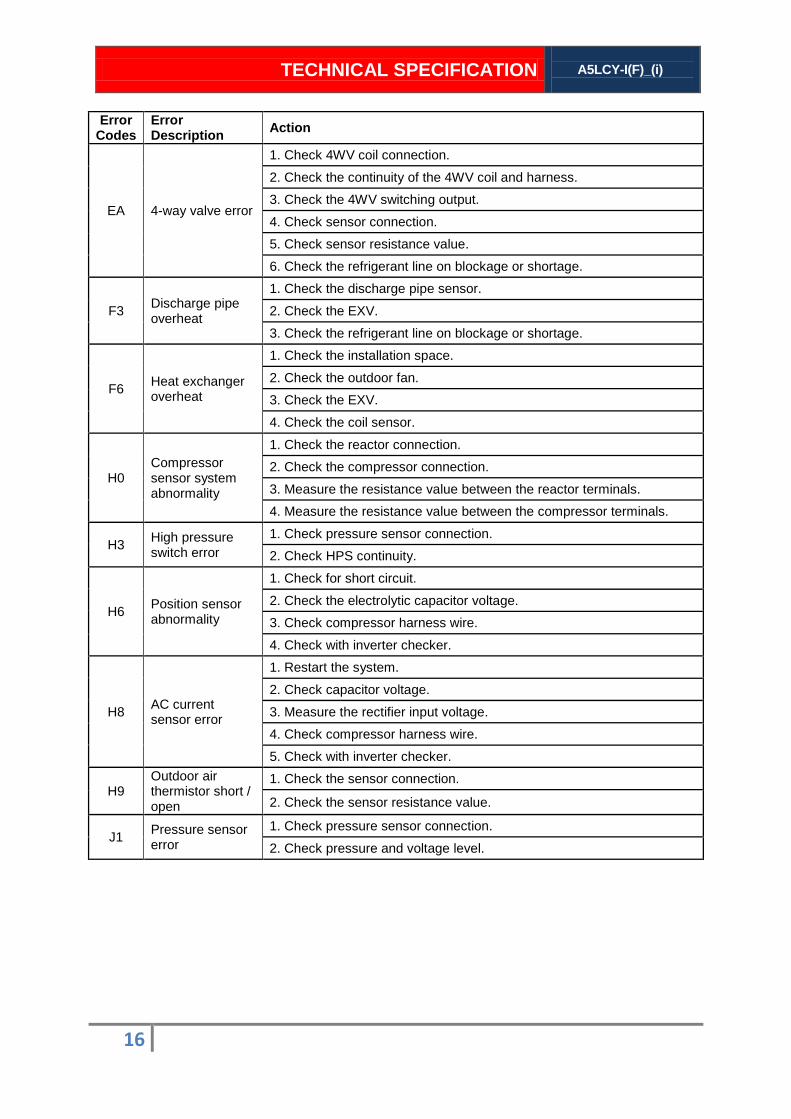
Error Codes
Error Description Action
EA 4-way valve error
1. Check 4WV coil connection.
2. Check the continuity of the 4WV coil and harness.
3. Check the 4WV switching output.
4. Check sensor connection.
5. Check sensor resistance value.
6. Check the refrigerant line on blockage or shortage.
F3 Discharge pipe overheat
1. Check the discharge pipe sensor.
2. Check the EXV.
3. Check the refrigerant line on blockage or shortage.
F6 Heat exchanger overheat
1. Check the installation space.
2. Check the outdoor fan.
3. Check the EXV.
4. Check the coil sensor.
H0 Compressor sensor system abnormality
1. Check the reactor connection.
2. Check the compressor connection.
3. Measure the resistance value between the reactor terminals.
4. Measure the resistance value between the compressor terminals.
H3 High pressure switch error
1. Check pressure sensor connection.
2. Check HPS continuity.
H6 Position sensor abnormality
1. Check for short circuit.
2. Check the electrolytic capacitor voltage.
3. Check compressor harness wire.
4. Check with inverter checker.
H8 AC current sensor error
1. Restart the system.
2. Check capacitor voltage.
3. Measure the rectifier input voltage.
4. Check compressor harness wire.
5. Check with inverter checker.
H9 Outdoor air thermistor short / open
1. Check the sensor connection.
2. Check the sensor resistance value.
J1 Pressure sensor error
1. Check pressure sensor connection.
2. Check pressure and voltage level.
TECHNICAL SPECIFICATION
A5LCY-I(F)_(i)
17
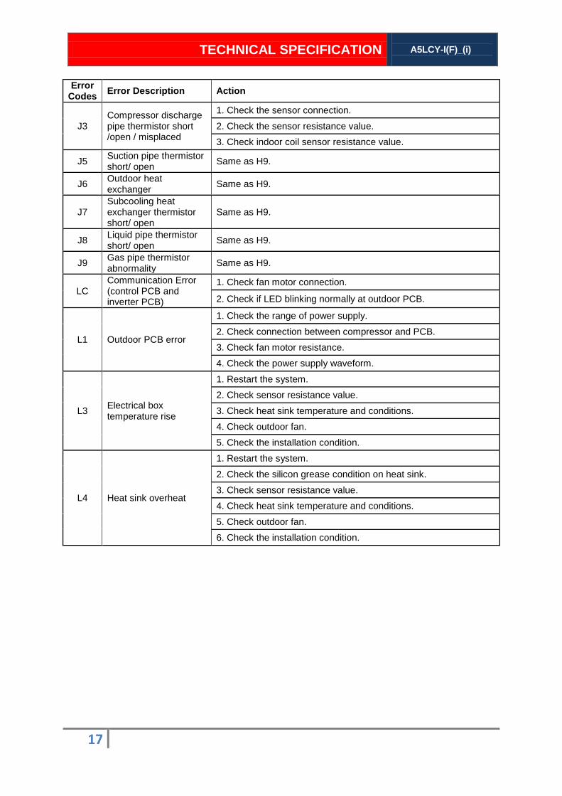
Error Codes Error Description Action
J3 Compressor discharge pipe thermistor short /open / misplaced
1. Check the sensor connection.
2. Check the sensor resistance value.
3. Check indoor coil sensor resistance value.
J5 Suction pipe thermistor short/ open Same as H9.
J6 Outdoor heat exchanger Same as H9.
J7 Subcooling heat exchanger thermistor short/ open
Same as H9.
J8 Liquid pipe thermistor short/ open Same as H9.
J9 Gas pipe thermistor abnormality Same as H9.
LC Communication Error (control PCB and inverter PCB)
1. Check fan motor connection.
2. Check if LED blinking normally at outdoor PCB.
L1 Outdoor PCB error
1. Check the range of power supply.
2. Check connection between compressor and PCB.
3. Check fan motor resistance.
4. Check the power supply waveform.
L3 Electrical box temperature rise
1. Restart the system.
2. Check sensor resistance value.
3. Check heat sink temperature and conditions.
4. Check outdoor fan.
5. Check the installation condition.
L4 Heat sink overheat
1. Restart the system.
2. Check the silicon grease condition on heat sink.
3. Check sensor resistance value.
4. Check heat sink temperature and conditions.
5. Check outdoor fan.
6. Check the installation condition.
TECHNICAL SPECIFICATION
A5LCY-I(F)_(i)
18
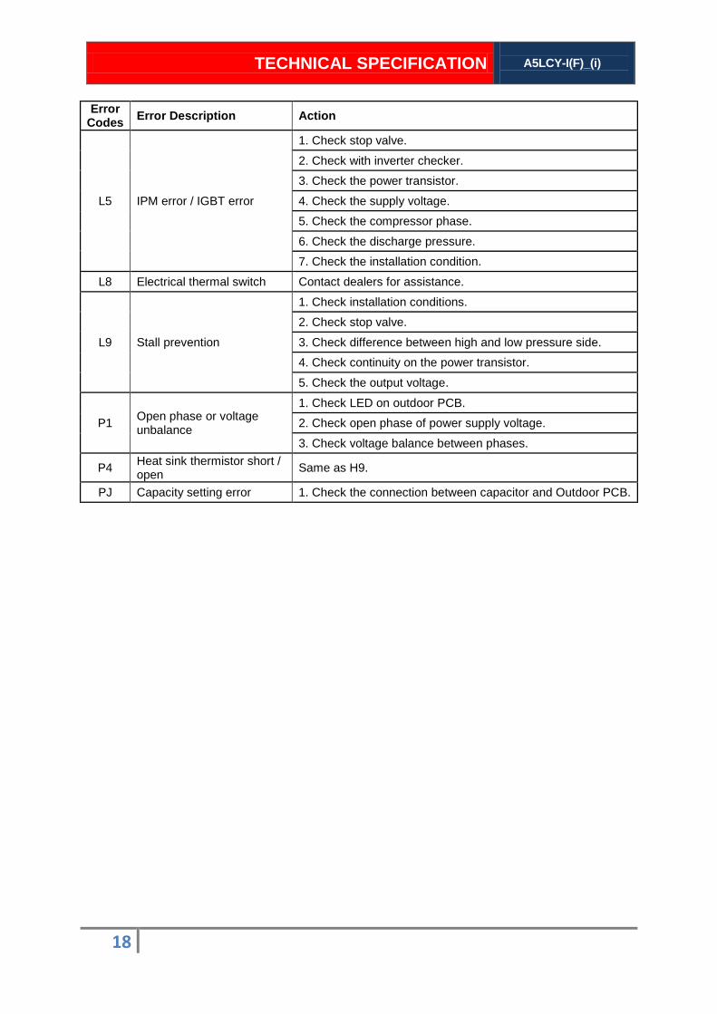
Error Codes Error Description Action
L5 IPM error / IGBT error
1. Check stop valve.
2. Check with inverter checker.
3. Check the power transistor.
4. Check the supply voltage.
5. Check the compressor phase.
6. Check the discharge pressure.
7. Check the installation condition.
L8 Electrical thermal switch Contact dealers for assistance.
L9 Stall prevention
1. Check installation conditions.
2. Check stop valve.
3. Check difference between high and low pressure side.
4. Check continuity on the power transistor.
5. Check the output voltage.
P1 Open phase or voltage unbalance
1. Check LED on outdoor PCB.
2. Check open phase of power supply voltage.
3. Check voltage balance between phases.
P4 Heat sink thermistor short / open Same as H9.
PJ Capacity setting error 1. Check the connection between capacitor and Outdoor PCB.
TECHNICAL SPECIFICATION
A5LCY-I(F)_(i)
19
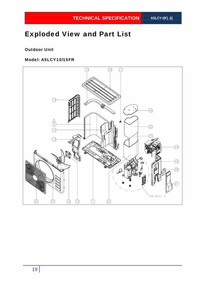
Outdoor Unit
Model: A5LCY10/15FR
Exploded View and Part List
TECHNICAL SPECIFICATION
A5LCY-I(F)_(i)
20
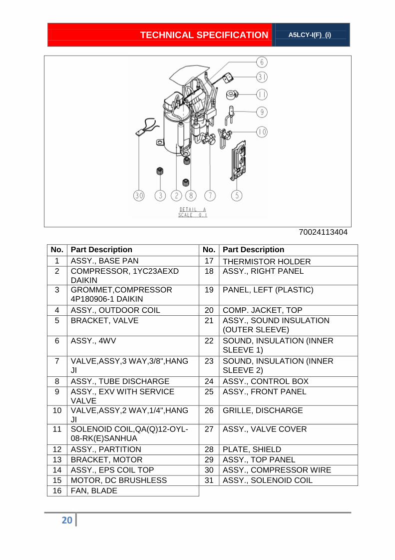
70024113404
No. Part Description No. Part Description 1 ASSY., BASE PAN 17 THERMISTOR HOLDER 2 COMPRESSOR, 1YC23AEXD
DAIKIN 18 ASSY., RIGHT PANEL
3 GROMMET,COMPRESSOR 4P180906-1 DAIKIN
19 PANEL, LEFT (PLASTIC)
4 ASSY., OUTDOOR COIL 20 COMP. JACKET, TOP 5 BRACKET, VALVE 21 ASSY., SOUND INSULATION
(OUTER SLEEVE) 6 ASSY., 4WV 22 SOUND, INSULATION (INNER
SLEEVE 1) 7 VALVE,ASSY,3 WAY,3/8",HANG
JI 23 SOUND, INSULATION (INNER
SLEEVE 2) 8 ASSY., TUBE DISCHARGE 24 ASSY., CONTROL BOX 9 ASSY., EXV WITH SERVICE
VALVE 25 ASSY., FRONT PANEL
10 VALVE,ASSY,2 WAY,1/4",HANG JI
26 GRILLE, DISCHARGE
11 SOLENOID COIL,QA(Q)12-OYL-08-RK(E)SANHUA
27 ASSY., VALVE COVER
12 ASSY., PARTITION 28 PLATE, SHIELD 13 BRACKET, MOTOR 29 ASSY., TOP PANEL 14 ASSY., EPS COIL TOP 30 ASSY., COMPRESSOR WIRE 15 MOTOR, DC BRUSHLESS 31 ASSY., SOLENOID COIL 16 FAN, BLADE
TECHNICAL SPECIFICATION
A5LCY-I(F)_(i)
21
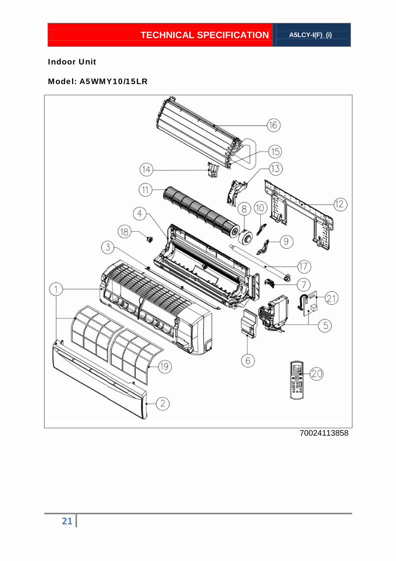
Indoor Unit
Model: A5WMY10/15LR
70024113858

TECHNICAL SPECIFICATION
A5LCY-I(F)_(i)
22
No. Part Description No. Part Description 1 ASSY., FRONT GRILLE ACSON -
INVERTER 12 ASSY., INSTALLATION PLATE
2 ASSY., PANEL (ACSON - INVERTER)
13 RIGHT SIDE PANEL
3 ASSY., DISC.GRILLE.HOR.BLADE
14 DRIP PROOF COVER
4 BOTTOM FRAME ASSY 15 CLIP, COIL SENSOR 5 ASST., CONTROL BOX 16 ASSY., COIL 6 ASSY., SERVICE COVER 17 ASSY., DRAIN HOSE 7 ASSY., PIPING FIXTURE 18 FAN BEARING VIBRATION
ABSORBER SET 8 MOTOR 19 AIR FILTER 9 MOTOR MOUNTING PLATE (1) 20 HANDSET, WIRELESS APGS02
ACSON 10 MOTOR MOUNTING PLATE (2) 21 ASSY., PCB (WITH LAMP COVER) 11 BLOWER, CROSS FLOW

TECHNICAL SPECIFICATION
A5LCY-I(F)_(i)
23
Product manufactured in an ISO certified facility. This document contains the most current information as of this orienting.
For the most up to date product information, please go to www.acson-international.com

Revision History List Manual : Inverter Y Wall Mounted L Series TM : A5LCY-IF_(i)
Revision Subject Amendment on Manual’s Page No. Date
01 1. Correction on Outdoor Dimension 7 02.02.2012


![Acson Service Guide Book 2010[1]](https://static.documents.pub/doc/80x56/543fc32bafaf9ff7098b49d6/acson-service-guide-book-20101.jpg)

