FORM NO. 49095 (REV. 4/7/08)PRINTED IN USA
xxxxxxxxxxxxxxxxxxxxxxxxxxxxxxxxxxxxx
xxxxxxxxxxxxxxxxxxxxxxxxxxxxxxxxxxxxxxxxxx
xxxxxxxxxxxxxxxxxxxxxxxxxxxxxxxxxxxxxxxxxxx
xxxxxxxxxxxxxxxxxxxxxxxxxxxxxxxxxxxxxxxxx
xxxxx
xxxxx
xxxxxx
xxx
xxxxx
xxxxx
xxxxxx
xxx
xxxxxxxxxxxxxxxx
xxxxx xxxxxx
xxxxxx xxxxx
xxx xxxxxx
APPLICATION TIPS
TOW BROADCAST SPREADERESPARCIDOR DE AMPLIO ALCANCE DE
REMOLQUE
ÉPANDEUR-AÉRATEUR À GRANDE PORTÉE À REMORQUER
OWNERS MANUALMANUAL DEL USUARIONOTICE D’UTILISATION
CAUTION:Read Rules forSafe Operation
and InstructionsCarefully
Model No.Modelo No. Modèle No.
45-02114
ATTENTION:Lire et suivre attentivement
les instructions et consignes de sécurité de cette notice.
PRECAUCION: Lea cuidadosamente los Procedimientos e Instrucciones para la
Operación Segura de la Máquina.
• Safety• Assembly• Operation• Maintenance• Parts
• Seguridad• Montaje• Operación• Mantenimiento• PiezasdeRepuesto
• Sécurité• Assemblage• Fonctionnement• Maintenance• PiècesdeRechange
the fastest way to purchase parts www.speedepart.com
™
2
1. HitchTube2. Flow Control Arm3. HitchBracket4. FlowControlMountBracket5. Braces(2)6. Flow Control Rod7. Wheels(2)8. HopperAssembly HardwarePack(seepage3)
5 6 7
1
4
8
2 3
OFF
ON
1234
678
910
5
1. TubodeEnganche2. BrazodelControldeFlujo3. SoportedeEnganche4. SoportedeMontajedelControldeFlujo
5. Puntales (2)6. BarradeControldeFlujo7. Ruedas (2)8. Tapa de la Tolva Paquete de Elementos de Ferretería (vea la página 3)
CARTON CONTENTS (Loose Parts in Carton)
CONTENIDO DE LA CAJA(PartesSueltasenlaCaja)
CONTENU DU CARTON(PiècesenVracDansleCarton)
FRANÇAISESPAÑOLENGLISH
1. Tubed’attelage2. Brasdecontrôlededébit3. Supportd’attelage4. Support de montage du contrôle dedébit
5. Entretoisesd’attelage(2)6. Bielledecontrôlededébit7. Roues (2)8. Couvercle de la trémie Sac de visserie (voir page 3)
3
REF. QTy. DESCRIPTION
A 5 HexBolt,1/4-20x1-1/2"
B 4 HexBolt,1/4-20x1"
C 1 CarriageBolt,1/4-20x3/4"
D 9 NylockNuts,1/4-20Thread
E 4 NylonWasher
F 6 FlatWasher,5/16"
G 4 FlatWashers,5/8"
H 1 CotterPin,3/32"x3/4"
I 1 CotterPin,5/32x2"
DCBA
I
J
E
K
L M NO P
NOT SHOWN FULL SIZE
SHOWN FULL SIZE
F
HG
Q
REF. QTy. DESCRIPTION
J 1 Hair Cotter Pin
K 1 HitchPin
L 2 Spacers
M 1 Nylon Wing Nut
N 1 AdjustableStop
O 1 FlowControlLink
P 1 Grip
Q 2 HubCap
4
ASSEMBLy INSTRUCTIONS
TOOLS REQUIRED FOR ASSEMBLy(1) Pliers(2) 7/16"Wrenches(1) Hammer
REMOVAL OF PARTS FROM CARTON
Removeallpartsandhardwarepackagesfromthecarton.Layoutallpartsandhardwareandidentifyusingtheillustrationson pages 2 and 3.
1. Turnthespreaderupsidedownasshowninfigure1.
FIGURE 1
RULES FOR SAFE OPERATION
Anypowerequipmentcancauseinjuryifoperatedimproperlyoriftheuserdoesnotunderstandhowtooperatetheequipment.Exercisecautionatalltimeswhenoperatingequipment.
LOOKFORTHISSYMBOLTOPOINTOUTIMPORTANTSAFETYPRECAUTIONS.ITMEANS—ATTENTION!BECOMEALERT!YOURSAFETYISINVOLVED.
• Read the towing vehicle ownersmanual and towingvehiclesafetyrules.Knowhowtooperateyourtractorbeforeusingthebroadcastspreaderattachment.
• Readthechemicallabelinstructionsandcautionsforhandling and applying the chemicals purchased forspreading.
• Weareyeandhandprotectionwhenhandlingandwhenapplyinglawnorgardenchemicals.
• Neveroperatetractorandspreaderattachmentwithoutwearingsubstantialfootwear,anddonotallowanyonetorideorsitonspreaderattachmentframe.
• Neverallowchildrentooperatethetractororspreaderattachment,anddonotallowadultstooperatewithoutproper instructions.
• Alwaysbeginwiththetransmissioninfirst(low)gearandwiththeengineatlowspeed,andgraduallyincreasespeed as conditions permit. Maximum towing speed -10M.P.H.
• Whentowingbroadcastspreaderdonotdrivetoocloseto a creek or ditch and be alert for holes and otherhazardswhichcouldcauseyoutoloosecontrolofthebroadcastspreaderandtractor.
• Beforeoperatingvehicleonanygrade(hill)refertothesafetyrulesinthevehicleowner'smanualconcerningsafe operation on slopes. Stay off steep slopes!
• Follow maintenance and lubrication instructions asoutlinedinthismanual.
ENGLISH
5
FIGURE 2
FIGURE 3
2. Assemblethetwohitchbracestotheinsideofthehopperframe,oneoneachside,usingtwo1/4"x1-1/2"hexbolts(A)andtwo1/4"nylocknuts(D).DO NOT TIGHTEN yET.Seefigure2.
3. Removethenutfromthemiddleboltinthecrossovertubeandshaftsupportplate.Leavetheboltinplace.Seefigure2.
4. Assemblethehitchtubeontothemiddleboltandsecureitwiththesamenutyouremoved.DO NOT TIGHTEN yET.Seefigure2.
IMPORTANT:Thehitchtubemustattachtothesideofthecrossovertubeoppositetheshaftsupportplate.
5. Assemblethetwohitchbracestothehitchtubeusinga1/4"x1-1/2"hexbolt(A)anda1/4"nylocknut(D).DO NOT TIGHTEN yET.Seefigure2.
6. Tighten thenutsandboltsfasteningthehitchbracesto thehopper frameand thehitch tube, then tightenthe middle lock nut fastening the hitch tube to thecrossovertube.DO NOT COLLAPSE TUBES WHEN TIGHTENING.
(A) 1/4" x 1-1/2"HEX BOLTS
(D) 1/4"NYLOCKNUTS
CROSSOVERTUBE
HITCH BRACE
HITCHTUBE
SHAFTSUPPORTPLATE
MIDDLENUT
MIDDLE BOLT
HITCH BRACE
7. Selecttheendoftheaxlewithnocrosshole.Assembleaspacer(L),a5/8"flatwasher(G),awheel(airvalvefacingout)andthenanother5/8"flatwasher(G)ontotheaxle.Seefigure3.
8. Installahubcap(Q)bytappingitcarefullyontotheaxlewithahammer.Seefigure3.
(L) SPACER
(G) 5/8" DIA.FLAT WASHER
(Q) HUB CAP
AIR VALVE
ENGLISH
FIGURE 4
9. Select theendof theaxlecontaining thecrosshole.Assembleaspacer(L),a5/8"flatwasher(G),awheel(airvalvefacingout)andthenanother5/8"flatwasher(G)onto theaxle. Insert the5/32" x2" cotterpin (I)throughthewheelhubandtheaxleandthenspreadtheendsofthepin.Seefigure4.
10. Installahubcap(Q)bytappingitcarefullyontotheaxlewithahammer.Seefigure4.
(I) 5/32" x 2"COTTER PIN
AIR VALVE
(L) SPACER
(G) 5/8" DIA.FLAT WASHER(Q) HUB CAP
6
17. Placea5/16"flatwasher(F)ontotheendoftheflowcontrolrod.Inserttheendoftherodthroughtheslotintheflowcontrolmountingbracketandthroughtheholeintheflowcontrollink(O).Securewitha3/32"x3/4"cotterpin(H).Seefigure8.
FIGURE 8
11. Turnthespreaderuprightonitswheels.12. Assemblethehitchbrackettothetopofthehitchtubeusingtwo1/4"x1"hexbolts(B)and1/4"nylocknuts(D).Seefigure5.
13. Assemble thehitchpin (K) through thehitchbracketandthehitchtubeandsecurewiththehaircotterpin(J).Seefigure5.
FIGURE 5
14. Assembletheflowcontrollink(O)(endwithsmallhole)totheflowcontrolarmusinga1/4"x1"hexbolt(B),anylonwasher(E)anda1/4"nylocknut(D).Tighten carefully. Theflowcontrollinkshouldnotbeloosebutshouldpivotwithnomorethanslightresistance.Seefigure6.
FIGURE 6
15. Assemble the flow control arm to the flow controlmountingbracketusinga1/4"x1"hexbolt (B), twonylonwashers(E)anda1/4"nylocknut(D)asshowninfigure7.Tighten carefully. Theflowcontrolarmshouldpivotwithaslightresistance.
16. Assemblethevinylgrip(P).Seefigure7.
FIGURE 7
(B) 1/4" x 1"HEX BOLT
(D) 1/4"NYLOCK NUT
FLOW CONTROLMOUNTINGBRACKET
FLOW CONTROL
ARM
(E) 2 NYLONWASHERS
(P) VINYL GRIP
ENGLISH
(B) 1/4" x 1"HEX BOLT
(D) 1/4" NYLOCKNUT
(K) HITCH PIN
(J) HAIR COTTER PIN
(O) FLOW CONTROLLINK
FLOW CONTROL
ARM
(D) 1/4"NYLOCK NUT
(B) 1/4" x 1"HEX BOLT
SMALLEST HOLE
(E) NYLONWASHER
FLOWCONTROL
ROD
(O) FLOW CONTROL
LINK
(H) 3/32"COTTER
PIN (F) 5/16" FLAT
WASHER
SLOT
7
18. Hookthefreeendoftheflowcontrolrodthroughtheholeintheslidegatebracketlocatednearthebottomofthehopper.Seefigure9.
FIGURE 9
19. Assembletheflowcontrolmountingbrackettothehitchtubeusingtwo1/4"x1-1/2"hexbolts(A),four
5/16"flatwashers(F)andtwo1/4"nylocknuts(D)asshowninfigure10. Do not tighten at this time.
FIGURE 10
20. Placetheadjustablestop(N)intothe"ON"endoftheslotinthetopoftheflowcontrolmountingbracket.Securewiththe1/4"x3/4"carriagebolt(C),anylonwasher(E),a5/16"flatwasher(F)andthenylonwingnut(M).Seefigure11.
FIGURE 11
(F) 5/16" FLATWASHER
OFF
ON
1234
678
910
5(E) NYLONWASHER
(C) 1/4" x 3/4"CARRIAGE BOLT
(M) NYLONWING NUT
(N) ADJUSTABLESTOP
ENGLISH
21. Positiontheflowcontrolmountingbracket(figure12).a. Pushon flowcontrol armuntil it locks in "OFF"
position.b. Slideflowcontrolmountingbracketalongtubeuntilclosureplateinbottomofhopperjustcloses.
c. Snugthemountingboltsjustenoughtoholdflowcontrolmountingbracketinplace.
d. Set adjustable stopat "5".Pull flowcontrol armagainststop.Verifythatclosureplatehasopenedabouthalfway.
e. Ifclosureplatedoesnotopenhalfway,itmaybeclosedtoofarat"OFF".Adjustpositionofflowcontrolmountingbracketuntilclosureplatewillopenabouthalfwayat"5"andstillclosewhenarmislockedin"OFF".Tightenmountingbolts.
FIGURE 12
FLOW CONTROLMOUNTING BRACKET
(A) 1/4" x 1-1/2"HEX BOLT
(D) 1/4" NYLOCKNUT
OFF
ON
12
34
67
89
10
5
(F) 5/16" FLATWASHER
OFF
ON
1234
678
910
5
FLOWCONTROL
ARM
ON
OFF
AJDUSTABLESTOP
SETTING "5"
MOUNTING BOLTS
8
FIGURE 13
OPERATING SPEED -3MPH.(100ft.in23seconds)
IMPORTANT: Application rates shown in the chart areaffected by humidity and by the moisture content ofthe material (granular and pellet). Some minor settingadjustments may be necessary to compensate for thiscondition.
OVERLAP
REFER TO
CHARTS
USING yOUR SPREADER
We do not recommend the use of any powdered lawnchemicals, due to difficulty in obtaining a satisfactory orconsistentbroadcastpattern.1. Determineapproximatesquarefootageofareatobe
covered and estimate amount of material required.2. Beforefillingthehoppermakesuretheflowcontrolarmisintheoffpositionandtheclosureplateisshut.
3. Breakupanylumpyfertilizerasyoufillthehopper.4. Settheadjustablestopwiththeflowcontrolarmstillintheoffposition.Refertotheapplicationchartonthispageandtotheinstructionsonthefertilizerbagtoselecttheproperflowratesetting.
5. Theapplication chart is calculated for light to heavyapplicationatavehiclespeedof3mph,or100ft.in23seconds.Avariationinspeedwillrequireanadjustmentof theflow rate tomaintain thesamecoverage.Thefasteryoudrive,thewiderthebroadcastwidth.
6. Alwaysstartthetractorinmotionbeforeopeningclosureplate.
7. Alwaysshuttheclosureplatebeforeturningorstoppingthetractor.
8. Iffertilizerisaccidentallydepositedtooheavilyinasmallarea,soaktheareathoroughlywithagardenhoseorsprinklertopreventburningofthelawn.
9. Toinsureuniformcoverage,makeeachpasssothatthebroadcastpatternslightlyoverlapsthepatternfromthepreviouspassasshowninfigure13.Theapproximatebroadcastwidths fordifferentmaterialsareshown intheapplicationchartonthispage.
10.Whenbroadcastingweedcontrolfertilizers,makesurethe broadcast pattern does not hit evergreen trees,flowersorshrubs.
11. Heavymoistureconditionsmayrequireacoveroverthehoppertokeepcontentsdry.Thevinylcover(availableasanaccessory)actsasawindandmoistureshield,butshouldnotbeusedasa raincover.Refer to theparts list on page 19.
HOW TO USE yOUR SPREADER
SETTING THE FLOW CONTROL(Refertofigure12onpage7.)
1. Loosenthenylonwingnut,settheadjustablestoptothedesiredflowratesettingandretightenthewingnut.Thehigherthesettingnumber,thewidertheopeninginthebottomofthehopper.
2. Refer to the application chart on page 8 and to theinstructionson the fertilizerbag to select theproperflowratesetting.
3. Pull theflowcontrolarmagainst theadjustablestopfor theonpositionand toward thehopper for theoffposition.
OPERATIONENGLISH
APPLICATION CHART
MATERIALTyPE
FLOW SETTING SPREADWIDTH
FERTILIZER
Powder 3-5 3'-4'
Granular 3-5 8'-10'
Pelleted 3-5 10'-12'
Organic 6-8 6'-8'
GRASS SEED
Fine 3-4 6'-7'
Coarse 4-5 8'-9'
ICE MELTER 6-8 10'-12'
9
CHECK FOR LOOSE FASTENERS1. Beforeeachusemakeathoroughvisualcheckofthespreaderforanyboltsandnutswhichmayhaveloosened.Retightenanylooseboltsandnuts.
CHECK FOR WORN OF DAMAGED PARTS2. Check for worn or damaged parts before each use.
Repair or replace parts if necessary.
CHECK TIRE INFLATION3. Checkiftiresareadequatelyinflatedbeforeeachuse.Donotinflatebeyondmaximumrecommendedpressure.
CLEANING
FIGURE 14
1. Rinseinsideofhopperandexteriorofspreaderanddryoffbeforestoring.
2. Storeinaclean,dryarea.
CAUTION: DO NOT inflatetiresbeyondthemaximum recommended pressure printed on side of tire.
4. Rinseinsideofhopperandexteriorofspreaderanddryoffbeforestoring.
LUBRICATE (Seefigure14.)5. Lightly apply automotive grease as needed to thesprocketandgear.
6. Oil thenylonbushingson thevertical sprocketshaftandontheaxleatleastonceayear,ormoreoftenasneeded.
7. Oilrighthand(idler)wheelbearingatleastonceayearor more often as needed.
FIGURE 15
MAINTENANCE
GREASE
OIL
OIL
STORAGE
1. If the axle, slotted gear and sprocket assembly isdisassembled,markdownthepositionsofthepartsastheyareremoved.Thedrivewheelandsprocketpositionsinrelationtotheslottedgeardeterminewhichdirectionthespreaderplatewillspin.Besuretoreassemblethemintheiroriginalpositions.(Refertofigure4onpage5.)Useshimwashers(Ref.no.21onpages18and19)asneededforminimumbacklash.Addgreasetogearandsprocket.
2. Iftheagitatorhairpinbecomesdamagedorwornitcanbereplaced.Seefigure15.
SERVICE AND ADJUSTMENTSENGLISH
SPROCKETSHAFT
AGITATOR HAIRPIN
10
• Leaelmanualdelpropietarioylasreglasdeseguridaddelvehículodearrastre.AprendacómooperarsutractorantesdeusarelimplementoEsparcidordeLanzado.
• Lealasinstruccionesylasprecaucionesqueseencuentranen la etiqueta del producto para conocer todo lo relativo almanejoyaplicaciónde lassustanciasquímicasquehacomprado para ser aplicadas.
• Useprotecciónparaojosymanoscuandomanejeycuandoapliquesustanciasquímicasparacéspedoparajardín.
• Nuncaopereeltractoryelimplementoesparcidorsinestarmuybiencalzado,ynopermitaquenadiesemonteosesiente en el marco del esparcidor.
• Nuncapermitaquelosniñosopereneltractornielimplementoesparcidor, y no permita que ningún adulto los opere sinconocer antes las respectivas instrucciones.
• Siempreempiececonlatransmisiónenprimera(bajo)yconelmotorabajavelocidad,yaumentegradualmentelavelocidad,segúnlopermitanlascondiciones.
• Cuando arrastre el esparcidor de lanzado, no conduzcademasiado cerca de quebradas o zanjas, y esté alerta aloshuecosydemáspeligrosquepodríanhacerqueustedperdiera el control del esparcidor y del tractor.
• Antesdeoperarelvehículoencualquiersuperficieinclinada(ocolina), consulte las reglasdeseguridadqueaparecenen el manual del propietario del vehículo, relativas a laoperación segura en colinas. !Manténgase alejado de colinas empinadas!
• Sigalasinstruccionesdemantenimientoylubricación,segúnsedescribenenestemanual.
ESPAÑOL
OBSERVEESTESIMBOLOPARAINDICARPRECAUCIONESIMPORTANTESDESEGURIDAD.¡SIGNIFICA — ATENCION! ¡ESTE ALERTA! ESTA INVOLUCRADA SU SEGURIDAD.
REGLAS PARA OPERACIONES SEGURASRecuerde,cualquierequipomotorizadopuedecausarlesionessiseoperaincorrectamenteosielusuarionoentiendecómooperarelequipo.Seaprecavidoentodomomentoalusarequipomotorizado.
11
IMPORTANTE:Eltubodeenganchedebefijarseenelladodeltubodecruce,opuestoalaplacadesoportedeleje.
5. Instalelosdospuntalesdeengancheeneltubodeenganche,usandounpernohexagonal(A)yunatuerca(D).NO APRIETE TODAVIA.Vealafigura2.
6. Aprietelastuercasypernosquefijanlospuntalesdeenganchealmarcodelatolvayaltubodeengancheyluegoaprietelatuercadecierredelmedioquefijaeltubodeenganchealtubodecruce.NO OCASIONE EL COLAPSO DE LOS TUBOS AL APRETAR.
7. Enelextremodelejequenotienelaperforaciónatravés,instale,enesteorden:unespaciador(L),unaarandelaplana(G),unarueda(conlaválvuladeairemirandohaciaafuera)y,luego,otraarandelaplana(G).Vealafigura3.
8. Instalelatapadecubo(Q)golpeandocuidadosamenteenelejeconunmartillo.Vealafigura3.
9. Enelextremodelejequetienelaperforaciónatravés,instale,enesteorden:unespaciador(L),unaarandelaplana(G),unarueda(conlaválvuladeairemirandohaciaafuera)y,luego,otraarandelaplana(G).Inserteelpernohendido(I) a través delatapadecuboyelejey,luego,abralosextremosdelperno.Vealafigura4.
10.Instalelatapadecubo(Q)golpeandocuidadosamenteenelejeconunmartillo.Vealafigura4.
11. Coloque sobre sus ruedas el esparcidor, en posiciónvertical.
12. Instaleelsoportedeenganchesobreeltubodeengancheusando2pernoshexagonales(B)ytuercas(D).Vealafigura5.
ESPAÑOL
ARMADO
HERRAMIENTAS REQUERIDAS PARA EL ARMADO (1) Pinzas(2) Llaves de 7/16”(1) Martillo
Saque del cartón de empaque todas las partes y los paquetes de ferretería. Extienda todas las partes y la ferretería e identifíquelos usando las ilustraciones de las páginas 2 y 3.
Nota: Lamanoderechay la izquierdasedeterminandesde laposicióndeloperadorsentadoenelvehículodearrastre.Nota: lasfigurasdelarmadoseencuentranen laspáginasde4 a 7.
1. Volteebocaabajoelesparcidorsegúnsemuestraenlafigura1.
2. Instalelosdospuntalesdeengancheenelinteriordelmarcodelatolva,usandounpernohexagonal(A)yunatuerca(D)en cada lado. NO APRIETE TODAVIA.Vealafigura2.
3. Remuevalatuercadelpernodelmedioeneltubodecruceylaplacadesoportedeleje.Dejeelpernoensulugar.Vealafigura2.
4. Instale el tubo de enganche sobre el perno del medio yasegúreloconlamismatuercaqueremovió.NO APRIETE TODAVÍA.Vealafigura2.
13. Instale el pernodeenganche (K) a través del soporte deengancheydeltubodeengancheyasegúrelosconelpasadordealeta(J).Vealafigura5.
14. Instaleeleslabóndecontroldeflujo(O)(porelextremodelagujeropequeño)enelbrazodecontroldeflujousandounpernohexagonal(B),unaarandeladenilón(E)yunatuerca(D). Apriete con cuidado.Elvínculodecontroldeflujonodebequedarflojo,perodebepodergiraroponiendomuypocaresistencia.Vealafigura6.
15. Ensamble el brazo de control de flujo en el soporte demontaje del control de flujo, usando un perno hexagonal(B),dosarandelasdenylon (E)yuna tuerca (D).Apriete cuidadosamente. Elbrazodecontroldeflujodeberáajustarsinholgura,ydeberágirarconapenasunaleveresistencia.Vealafigura7.
16. Ensambleelmangodevinilo(P)enelbrazodecontroldeflujo.Vealafigura7.
17. Coloqueunaarandelaplana(F)sobreelextremodelabarradecontroldeflujo.Inserteelextremodelabarraatravésdelaranuracurvadaenelsoportedemontajedecontroldeflujo(O),yatravésdelhuecoeneleslabóndecontroldeflujo.Asegureconunpernohendido(H).Vealafigura8.
18.Engancheelextremolibredelabarradecontroldeflujoatravésdelagujerodelsoportedelacompuertamóvilubicadocercadelfondodelatolva.Vealafigura9.
19. Instaleelsoportedemontajedecontroldeflujoeneltubodeengancheusandodospernoshexagonales(A),cuatroarandelas planas (F) y dos tuercas (D) como se muestra en lafigura10.No apriete todavía.
20. Coloqueelelementoajustabledeparada(N)enelextremo“ON”(ABIERTO)delaranuraenlapartesuperiordelsoportedemontaje del control de flujo. Asegure con el perno decarruaje(C),unaarandeladenylon(E),unaarandelaplana(F)ylatuercademariposadenylon(M).Vealafigura11.
21. Coloqueelsoportedemontajedelcontroldeflujo(Figura12).a. Empujeelbrazodecontroldeflujohastaqueajusteen
posición “OFF” (CERRADO).b. Desliceelsoportedemontajedelcontroldeflujoalolargodeltubo,hastaquelaplacadetaponamientoenelfondode la tolva apenas cierre.
c. Ajuste las tuercas de cierre, apenas lo suficiente parasostenerensulugarelsoportedemontajedelcontroldeflujo.
d. Gradúeelelementoajustabledeparadaen“5”.Tiredelbrazodecontroldeflujocontraelelementodeparada.Verifiquequelaplacadetaponamientohayaabiertomásomenoshastalamitad.
e. Silaplacadetaponamientonoabrehastalamitad,ajustelaposicióndeelsoportedemontajedelcontroldeflujohastaque laplacade taponamientoabrahastamásomenos la mitad en “5” y se mantenga cerrada cuando el brazoquedeajustadoenlaposición“OFF”(CERRADO).Apriete las tuercas de cierre de 1/4”.
12
ESPAÑOL
USO DEL ESPARCIDORNorecomendamoselusodesustanciasquímicasenpolvo,nogranuladas,paraelcésped,debidoaladificultaddeobtenerunpatróndelanzadosatisfactoriooconsistente.1. Determinelamedidaaproximadadeláreaquesevaacubrirenpiesometroscuadrados,yestimelacantidaddematerialque necesita.
2. Antes de llenar la tolva, asegúrese de que el brazo decontroldeflujoestéenposicióndeCERRADO,ylaplacadetaponamiento esté cerrada.
3. Nousefertilizanteapelmazado,yseparelosterronesamedidaque llena la tolva.
4. Gradúeelelementoajustabledeparada,manteniendoelbrazodecontroldeflujoenlaposicióncerrada.Refiérasealcuadrodeaplicaciónenestapáginayalasinstruccionesenlabolsadelfertilizanteparaseleccionarlagraduaciónadecuadaparalatasadeflujo.
5. El cuadro de aplicación está calculado para una aplicación de ligeraapesada,aunavelocidaddelvehículode3MPH(4,8km/h),sea30metrosen23segundos.Cualquiervariacióndelavelocidadrequeriráunajustedelatasadeflujoparamantener el mismo cubrimiento. A mayor velocidad, másampliaserálaanchuradellanzado.
6. Siempre arranque y ponga el tractor en movimiento antes de abrirlaplacadetaponamiento.
7. Siempre cierre la placa de taponamiento antes de girar o detener el tractor.
8. Siaccidentalmenteelfertilizanteseacumulademasiadoenunáreapequeña,empapeafondoeláreaconunamangueradejardínounrociador,paraevitarqueelcéspedsequeme.
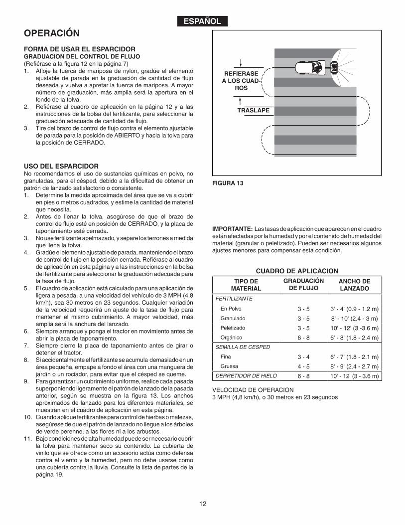
9. Paragarantizaruncubrimientouniforme,realicecadapasadasuperponiendoligeramenteelpatróndelanzadodelapasadaanterior, según se muestra en la figura 13. Los anchosaproximadosdelanzadoparalosdiferentesmateriales,semuestran en el cuadro de aplicación en esta página.
10.Cuandoapliquefertilizantesparacontroldehierbasomalezas,asegúresedequeelpatróndelanzadonolleguealosárbolesdeverdeperenne,alasfloresnialosarbustos.
11. Bajocondicionesdealtahumedadpuedesernecesariocubrirla tolva paramantener seco su contenido. La cubierta deviniloqueseofrececomounaccesorioactúacomodefensacontraelvientoy lahumedad,peronodebeusarsecomounacubiertacontralalluvia.Consultelalistadepartesdelapágina 19.
OPERACIÓN
FORMA DE USAR EL ESPARCIDORGRADUACION DEL CONTROL DE FLUJO(Refiérasealafigura12enlapágina7)1. Afloje la tuercademariposadenylon,gradúeelelementoajustabledeparadaen lagraduacióndecantidaddeflujodeseada y vuelva a apretar la tuerca de mariposa. A mayor númerodegraduación,másampliaserá laaperturaenelfondo de la tolva.
2. Refiérasealcuadrodeaplicaciónen lapágina12ya lasinstruccionesdelabolsadelfertilizante,paraseleccionarlagraduaciónadecuadadecantidaddeflujo.
3. TiredelbrazodecontroldeflujocontraelelementoajustabledeparadaparalaposicióndeABIERTOyhacialatolvaparala posición de CERRADO.
IMPORTANTE: Las tasas de aplicación que aparecen en el cuadro estánafectadasporlahumedadyporelcontenidodehumedaddelmaterial(granularopeletizado).Puedensernecesariosalgunosajustesmenoresparacompensarestacondición.
VELOCIDAD DE OPERACION3MPH(4,8km/h),o30metrosen23segundos
FIGURA 13
OVERLAP
REFER TO
CHARTS
REFIERASEA LOS CUAD-
ROS
TRASLAPE
CUADRO DE APLICACION
TIPO DEMATERIAL
GRADUACIÓNDE FLUJO
ANCHO DELANZADO
FERTILIZANTE
En Polvo 3-5 3'-4'(0.9-1.2m)
Granulado 3-5 8'-10'(2.4-3m)
Peletizado 3-5 10'-12'(3-3.6m)
Orgánico 6-8 6'-8'(1.8-2.4m)
SEMILLA DE CESPED
Fina 3-4 6'-7'(1.8-2.1m)
Gruesa 4-5 8'-9'(2.4-2.7m)
DERRETIDOR DE HIELO 6-8 10'-12'(3-3.6m)
13
MANTENIMIENTO
REVISE SI HAy ELEMENTOS DE AJUSTE SUELTOS1. Antesdecadauso,realiceunarevisiónvisualdetalladadelesparcidorenbuscadepernoso tuercassueltoso flojos.Vuelvaaapretarlospernosolastuercasflojas.
REVISE SI HAy PARTES GASTADAS O DAÑADAS2. Antesdecadauso,revisesihaypartesgastadasodañadas.
Repare o reemplace las partes cuando sea necesario.
REVISE QUE LAS LLANTAS ESTEN BIEN INFLADAS3. Antesdecadauso,revisequelasllantasesténbieninfladas.Noinflemásalládelapresiónmáximarecomendada.
PRECAUCION: NO INFLE las llantas más allá de la presión máxima recomendada que aparece impresa en el costado de la llanta.
LIMPIEZA4. Lave el interior de la tolva y el exterior del esparcidor y seque bienantesdeguardarlaunidad.
LUBRICACION(Vealafigura14)5. Apliqueunacapaligeradegrasaparaautomóvil,segúnseanecesario,enlaruedadentadayelengranaje.
6. Aceitelosbujesdenylonenelejeverticaldelaruedadentadayenelejedelasruedas,porlomenosunavezalaño,oconmás frecuencia si es necesario.
7. Aceiteelcojinetedelaruedaderecha(engranajelibre),porlomenosunavezalañooconmásfrecuenciasegúnseanecesario.
FIGURA 14
GREASE
OIL
OIL
ACEITE
GRASA
ACEITE
ESPAÑOL
ALMACENAMIENTO
1. Lave el interior de la tolva y el exterior del esparcidor y séquelos bienantesdeguardarlaunidad.
2. Almacénela en un área limpia y seca.
SERVICIO y AJUSTES
1. Sielconjuntodeeje,engranajeranuradoyruedadentadase vaadesarmar,marque lasposicionesde laspartesamedida que las va removiendo. Las posiciones de la rueda delatransmisiónydelaruedadentada,enrelaciónconelengranajeranurado,determinan ladirecciónenquegirarálaplacadelesparcidor.Asegúresedevolverlosaensamblarensuposiciónoriginal.(Refiérasealafigura4enlapágina5).Usearandelasdecalza(Ref.No.21enpáginas18y19)según sea necesario, para que el retroceso sea mínimo.Agreguegrasaalengranajeyalaruedadentada.
2. Elalambreagitadorsepuedereemplazarsisegastaosedaña.Vealafigura15.
FIGURA 15
EJE DE LA RUEDA DENTADA
CAMISA DEL AGITADOR
14
CONSIGNES DE SÉCURITÉToutappareilmécaniquerisquedeprovoquerdesblessuressicederniern’estpasutilisécorrectementousi l’utilisateurnesaitpascommentl’utiliser.Faitespreuvedeprudenceàtoutmomentlorsquevousutilisezunappareilmécanique.
• Lisezcettenoticed’utilisationet lesconsignesdesécuritéavantdetenterd’assembleroud’utiliserlaremorque.Veillezàbienconnaîtrelefonctionnementdutracteuravantd’attelerlaremorqueàl’épandeur.
• Lisezlesinstructionsduproduitchimiqueetlesconsignesdesécuritéafindemanipuleretrépandrelesproduitschimiquesachetésafind’êtreutilisésavecl’épandeur.
• Portezdeslunettesdeprotectionetdesgantslorsquevousmanipulezetutilisezdesproduitschimiquespourjardinsetgazons.
• Nejamaisconduireletracteuretl’épandeursansporterdeschaussuresadéquates.Netransportezjamaispersonnesurl’attelagedel’épandeur.
• Nelaissezjamaisd’enfantsutiliserletracteurnilaremorqueetnelaissezaucunadulteutiliserletracteurnilaremorque sans lui avoir fourni auparavant les instructions adéquates.
CE SyMBOLE ATTIRE L’ATTENTION SUR DES MESURES DE SÉCURITÉ IMPORTANTES. IL SIGNIFIE : ATTENTION! DEMEUREZ VIGILANT! VOTRE SÉCURITÉ EN DÉPEND.
• Commencez toujours en veillant à ce que le levier de latransmissionsetrouveenpremièrevitesse(réglagebassur“low”)etaugmentezpetitàpetitvotrevitessesilesconditionsle permettent.
• Tractezlaremorqueàbassevitessesurterrainaccidenté,toutepenteouàproximitédetoutruisseauoufosséafind’éviterqu’elleneserenverseencasdepertedecontrôledutracteuretdel’épandeur.
• Avantd’utiliserlevéhiculesurtouteinclinaison(pente),reportez-vousauxconsignesdesécuritédelanoticed’utilisationconcernantlaconduiteduvéhiculesurtoutepenteoucolline.Demeurezàl’écartdetoutepenteforte!
• Veuillezsuivrelesinstructionsd’entretienetdelubrificationfigurantdanscettenotice.
FRANÇAIS
15
IMPORTANT:Letubed’attelagedoitvenirsefixersurlecôtédutubederaccordementenfacedelaplaquedesupportdel’axe.
5. Montezlesdeuxentretoisesd’attelagesurletubed’attelageenutilisantunboulonhex.(A)etuncontre-écrouhex.(D).Neserrezpaspourl’instant.Voirfigure2.
6. Serrez les écrous et les boulons retenant les entretoisesd’attelageaucadredelatrémieetautubed’attelage,puisserrezlecontre-écroucentralafindefixerletubed’attelageautubederaccordement.VEILLEZ À NE PAS PLIER OU ENDOMMAGER LE TUBE LORSQUE VOUS SERREZ LES BOULONS ET LES ÉCROUS.
7. Choisissezl’extrémitédel’essieuquinecomportepasdepetittrou.Montezuntubed’espacement(L),unerondelleplatede5/8po.(G),uneroue(aveclavalveversl’extérieur)etuneautrerondelleplatede5/8po.(G)surl’extrémitédel’essieu.Voirl’illustration3.
8. Montezuncache-moyeu(Q)surl’extrémitédel’essieuenutilisantunmarteauafindetaperlégèrementjusqu’àcequelecache-moyeusetrouvecontrelaroue.Voirl’illustration3.
9. Choisissezl’extrémitédel’essieuquicomportelepetittrouencroix.Montezuntubed’espacement(L),unepetiterondelleplatede5/8po.(G),uneroue(aveclavalveversl’extérieu)etuneautrerondelleplatede5/8po.(G)surl’extrémitédel’essieu.Insérezlagoupille-épinglede5/32x2po.(I)danslecache-moyeuetdansl’essieu,puisécartezlesextrémitésdelagoupille.Voirl’illustration4.
10.Montezuncache-moyeu(Q)surl’extrémitédel’essieuenutilisantunmarteauafindetaperlégèrementjusqu’àcequelecache-moyeusetrouvecontrelaroue.Voirl’illustration4.
FRANÇAIS
OUTILS NÉCESSAIRES POUR L’ASSEMBLAGE(1) Pinces(2) Clés de 7/16 po.(1) Marteau
Retirezl’épandeur,lespiècesetlematérieldefixationducarton.Étalez toutes les pièces et le matériel et reportez-vous auxillustrationsdespages2et3afind’identifiertouteslespièces.
REMARQUE : Ladroiteetlagauchesontdéfiniesàpartirdelapositiondel’opérateurlorsqu’ilestassissurletracteur.REMARQUE : Se reporterauxplansd’ensembledespages4à7.
1. Placez l’épandeur à l’envers comme illustré au niveau dudessinNo.1afinqu’ilreposesurlatrémie.
2. Fixezlesdeuxentretoisesd’attelageàl’intérieurducadredelatrémieenutilisantleboulonhex.po.(A)etlecontre-écrouhex.(D)dechaquecôté.NE PAS SERRER POUR L’INSTANT. Voirlafigure2.
3. Retirezlecontre-écroudubouloncentralsituédansletubederaccordementetlaplaquedesupportdel’axe.Laissezleboulonenplace.Voirlafigure2.
4. Montezletubed’attelagesurlebouloncentraletfixez-leaveclecontre-écrouquevousvenezderetirer.NE PAS SERRER POUR L’INSTANT.Voirlafigure2.
INSTRUCTIONS DE MONTAGE 11.Placezl’épandeurdeboutsursesroues.12.Fixezlesupportd’attelagesurledessusdutubed’attelageenutilisantdeuxboulonshex.de1/4x1po.(B)etdeuxécrousàfreinélastique(D).Voirl’illustration5.
13. Insérezlagoupilled’attelage(K)danslesupportd’attelageetdansletubed’attelagepuisfixezl’ensembleavecunegoupille-épingle(J).Voirl’illustration5.
14.Montezlabiellettedecontrôlededébit(O)(l’extrémitécomportantlepetittrouencroix)surlebrasdecontrôlededébitenutilisantunboulonhex.de1/4x1po.(B),unerondelleennylon(E)etunécrouàfreinélastique(D).Serrezavecprécaution.Labiellettedecontrôlededébitdevrait demeurer desserrée mais devrait pouvoir pivoter sans trop de résistance.
15. Fixezlebrasdecontrôlededébitausupportdemontagedecontrôlededébitenutilisantunboulonhex.(B),deuxrondellesennylon(E)etuncontre-écrou(D).Serrez avec précaution. Lebrasdecontrôlededébitdevraitêtreserrémaisdevraitpouvoirpivotersanstropderésistance.Voirlafigure7.
16. Montezlapoignéeenvinyle(P)surlebrasdecontrôlededébit.Voirlafigure7.
17. Placezunerondelleplate(F)surl’autreextrémitédelabielledecontrôledudébit.Introduisezl’extrémitédelabielledanslafentecourbéedusupportdemontageducontrôledudébitpuisdansletroudelabiellettedecontrôledudébit.Fixezlespiècesenutilisantunegoupille-épingle(H).Voirlafigure8.
18. Accrochezleboutpliédelabielledecontrôledudébitdansletroudelafixationdelaplaquecoulissantesituéeàproximitédufonddelatrémie.Voirfigure 9.
19. Montezlesupportdecontrôlededébitsurletubed’attelageenutilisantdeuxboulonshex.(A),quatrerondellesplates(F)etdeuxcontre-écroushex.(D)commeillustréàlafigure10.Ne serrez pas pour l’instant.
20.Placezlabutéeréglable(N)surl’extrémité«ON»(marche)dela fente qui est située sur le dessus du support de montage dumécanismedecontrôlededébit.Fixezlapièceenutilisantunboulondecarrosserie(C),unerondelleennylon(E),unerondelleplate(F)etl’écrouàoreillesennylon(M).Voirfigure11.
21. Positionnezlesupportdemontageducontrôlededébit(figure12).a. Poussezlebrasdecontrôlededébitjusqu’àcequ’ilsebloquesur«OFF»(arrêt).
b. Glissezlesupportdemontagedumécanismedecontrôlededébitlelongdutubejusqu’àcequelaplaquededébitdu fond de la trémie se ferme.
c. Serrezlescontre-écrousjusteassezafinqu’ilsretiennentle support de montage du mécanisme de contrôle dedébit.
d. Réglez labutéeréglablesur«5».Tirezsur lebrasdecontrôle de débit afin qu’il se trouve contre la butée.Assurez-vousque laplaquededébit sesoitouverteàmoitié.
e. Silaplaquededébitnes’ouvrepasàmoitié,ellerisqued’êtreferméetroploinsur«OFF».Réglezlapositiondusupportdemontagedumécanismedecontrôlededébitdefaçonàcequelaplaquededébits’ouvreenvironàmoitiéà«5»etensuitepuissesefermerlorsquelebrasestréglésur«OFF»(arrêt).Serrezlescontre-écrous.
16
FRANÇAIS
COMMENT UTILISER VOTRE ÉPANDEUR AÉRATEURRÉGLAGE DU DÉBIT(Reportez-vousàlafigure12delapage7)1. Desserrez l’écrouàoreillesennylonetréglez-labutéeré-glablesurledébitdésiréetresserrezl’écrouàoreilles.Plusleréglageesthaut,etplusl’ouvertureaufonddelatrémiesera large.
2. Reportez-vousautableaudelapage16etauxinstructionsfigurant sur l’emballage de l’engrais afin de déterminer leréglagedudébit.
3. Tirezlebrasdecontrôlededébitcontrelabutéeréglablepourlaposition«ON»(marche)etverslatrémiepourlaposition«OFF»(arrêt).
UTILISATION
UTILISATION DE L’ÉPANDEUR-AÉRATEURIlestdéconseilléd’utiliserdesengraischimiquesenpoudrecarcesdernierssontdifficilesàrépartiruniformémentavecl’épandeur.1. Déterminezlasuperficieapproximativeenpiedscarrés(oumètrescarrés)devantêtretraitéeetjugezlaquantitéd’engraisou de graines nécessaire.
2. Avant de remplir la trémie, assurez-vous que le bras decontrôlededebitsetrouvesurlaposition«OFF»(arrêt)etquelaplaquededébitestfermée.
3. Faitesensortesqueleproduitnefassepasdegrossesboulesaufuretàmesurequevousremplissezlatrémie.
4. Réglezlabutéeréglabletoutengardantlebrasdecontrôledudébitsurlaposition«OFF»(arrêt).Reportez-vousautableaudecettepageetauxinstructionsfigurantsurl’emballagedel’engraisafindedéterminerleréglagedudébit.
5. Lesdonnéesdutableaudesdébitsontétécalculéespourundébitfaibleàfortàunevitessedetractagede3m.p.h.(4,8km/h)soit30mètresen23secondes.Vousdevrezcorrigerledebitsivouschangezdevitesseafindecouvrirleterrainquevousdésirez.Plusvouscirculezviteetpluslaportéedel’épandeurseralarge.
6. Veillezàcequeletracteursoitentrainderouleravantd’ouvrirlaplaquededebit.
7. Assurez-vousquelaplaquededebitestferméeavantd’arreteroud’effectueruntournantavecletracteur.
8. Sivousvenezaccidentellementd’appliquertropd’engraissurunespaceréduit,aspergezabondammentcetendroitàl’aided’untuyaud’arrosageafind’éviterquelasurfacenebrûle.
9. Pourunecouvertureoptimaleetafind’éviterdemanquerdeszonesoudelaisserdestracesdepassages,chevauchezlestracesprécédentescommeillustréàlafigure13.Lesportéesapproximativesdesdifférentesmatièressontindiquéesdansletableaudesdébitsdecettepage.
10.Faites attention lorsque vous utilisez l’épandeur avec desherbicidesetdésherbantsetveillezàcequecesproduitsnetouchentpaslesbuissons,lesfleurs,etc.
11.En présence de conditions très humides, la trémie devraêtre équipéed’un couvercle afinde protéger son contenude l’humidité.Lecachedeprotectionenvinyle (disponibleenoptioncommeaccessoire),sertàprotégerl’épandeurduventetdel’humiditémaisnedoitpasêtreutiliséentantquecouvercledeprotectioncontrelapluie.Reportez-vousàlalistedespiècesdelapage19.
FIGURE 15
IMPORTANT:Lesdébitsindiquésdansletableausontaffectésparl’humiditéetparletypedematièrequevouscomptezrépandre(granulésetagglomérés).Certainsréglagesmineursrisquentd’êtrenécessairesafindecompenserleproblème.
VITESSE D’APPLICATION: 3m.p.h.(4,8km/h)soit30mètresen 23 secondes.
OVERLAP
REFER TO
CHARTS
REPORTEZ-VOUS AUX TABLEAUX
CHEVAUCHEMENT
TABLEAU DES DÉBITS
RÉGLAGEMATIÈRE
LARGEURDU DÉBIT
ET PORTÉE
ENGRAIS
Poudre 3-5 3'-4'(0.9-1.2m)
Granulés 3-5 8'-10'(2.4-3m)
Agglomérés 3-5 10'-12'(3-3.6m)
Organique 6-8 6'-8'(1.8-2.4m)
GRAINES DE GAZON
Fines 3-4 6'-7'(1.8-2.1m)
Grosses 4-5 8'-9'(2.4-2.7m)
SEL DE DÉGLAÇAGE 6-8 10'-12'(3-3.6m)
17
FRANÇAIS
VÉRIFIER QUE LA VISSERIE N’EST PAS DESSERRÉE1. Avanttouteutilisation,vérifiezattentivementquelesboulonset lesécrousde l’épandeurnesontpasdesserrés.Serreztoutboulonouécroudesserré.
VÉRIFIER QUE LES PIÈCES NE SONT PAS USÉES OUENDOMMAGÉES2. Vérifiezquelespiècesnesontpasuséesouendommagéesavantchaqueutilisation.Réparezouremplacezlapiècesinécessaire.
VÉRIFIER L’ÉTAT DES PNEUS3. Vérifiezquelespneussontcorrectementgonflésavantchaqueutilisation.Negonflezpaslespneusau-delàdelapressionmaximum recommandée.
FIGURE 14
1. Rincezl’intérieurdelatrémieetl’extérieurdel’épandeuretséchezletoutavantdeleranger.
2. Rangez et remisez l’épandeur dans un endroit propre etsec.
NETTOyAGE4. Rincezl’intérieurdelatrémieetl’extérieurdel’épandeuretséchezletoutavantdeleranger.
LUBRIFICATION(voirfigure14)5. Appliquezunpeudegraissepourautomobilessurlacouronneetl’engrenagesinécessaire.
6. Huilezlesfourruresennylondel’arbreverticaldelacouronneainsiquel’essieuaumoinsunefoisparanouplussouventsi nécessaire.
7. Huilezleroulementdroit(baladeur)aumoinsunefoisparanou plus souvent si nécessaire.
FIGURE 15
ENTRETIEN ET MAINTENANCE
ATTENTION: NE PASgonflerlespneusau-delàdelapressionmaximumrecommandéefigurantsurleflancdupneu.
REMISAGE
1. Sil’essieu,l’engrenageàfentesetl’ensembledelacouronnesontdémontés,indiquezaucrayonl’emplacementdespiècesaufuretàmesurequevouslesretirées.Lapositiondelaroued’entraînememtetdelacouronnedétermineralesensdanslequellaplaquedel’épandeurtournera.(Reportez-vousàlafigure4delapage5).Utilisezlescales(voirréf.21despages18et19)afind’éviterunjeutropimportant.Appliquezlagraissesurl’engrenageetlacouronne.
2. Silefildebattageestendommagéouusé,ilpeutêtreremplacé.Voirfigure15.
RÉPARATIONS ET RÉGLAGES
GREASE
OIL
OIL
HUILE
GRAISSE
HUILE
ARBRE DE LA COURONNE
FIL DE BATTAGE
18
REPAIR PARTS FOR BROADCAST SPREADER MODEL 45-02114
37
24 23
43
22
21 2021 22
19
18
4
D
E
35
22
16
37
37
39
23
A
A
37
15
27
2628
3
19
36
34
9
46
97 940
16
14
17
37
2422
9
E
9
29
5
4
9
35B
6
38
44
47
48
48
842
409
D45
11
48
29
40
38
49
25B
1
39
10
941
11
50
39
9
11
39
31
2
32
33
48
30
51
9
13
22
30
9
9
11
19
REPAIR PARTS FOR BROADCAST SPREADER MODEL 45-02114
REF. PART NO. QTy. DESCRIPTION1 44466 1 Hopper2 C-9M5732 2 Rivet,Pop3 62482 1 Ass'y,GuideClosure4 48842 1 Tube,Frame5 23753 1 SlideGateAngleBracket6 23758 1 SlideGateBracket7 44566 1 Spring,Torsion8 24857 1 FlowControlLink9 47189 22 Nut,Nylock1/4-2010 48841 1 Tube,Crossover11 R19111116 6 Washer,5/16SAE13 47063 1 Pin,Cotter5/32"x2"14 44586 1 Tube,Hitch15 46055 1 Pin,Spring1/8"Dia.x1"Lg.16 40880 2 Wheel17 23687 1 Bracket,Hitch18 25067 1 Shaft,Axle19 44665 2 Pin,Spring5/32"x1-1/4"20 48916 1 Bushing,AxleShaft21 44125 4 Washer,Flat5/8"x1"22 R19212016 5 Washer,Flat5/8"x1-1/4"23 741-0249 2 Bearing,Flange24 48857 2 Tube,Spacer25 25305 1 Shaft,Sprocket26 04367 1 Spreader Plate
*Purchasecommonhardwarelocally.
the fastest way to purchase parts www.speedepart.com
REF. PART NO. QTy. DESCRIPTION27 43850 1 Pin,Spring1/8"Dia.x5/8".28 44468 1 Sprocket,6Tooth29 44285 2 Bushing,Delrin30 48499 2 HubCap31 48934 1 Hairpin,Agitator32 47623 1 HitchPin33 43343 1 HairCotterPin,1/8"34 44469 1 Rod,FlowControl35 23525 2 Brace,Hitch36 23780 1 ShaftSupportPlate37 43648 9 Bolt,Hex1/4-20x1-1/2"38 1509-69 7 Bolt,Hex1/4-20x1-3/4"39 1543-69 10 Washer,Nylon40 43088 10 Washer,Flat1/4"Std.41 24858 1 Stop,Adjustable42 24855 1 Bracket,FlowControlMount43 48888 1 Gear,Slotted44 24859 1 Flow Control Arm45 44101 1 CotterPin3/32"x3/4"Lg.*46 23533 1 Plate,Closure47 43848 1 Grip,FlowControlArm48 43661 5 Bolt,Hex1/4-20x1"Lg.*49 44950 1 Bolt,Carriage1/4-20x3/4"x5050 47141 1 WingNut,Nylon51 43962 1 Vinyl Cover (Optional)
49095 1 Owner'sManual
REPAIR PARTSAgri-Fab,Inc.
303 West RaymondSullivan,IL.61951217-728-8388www.agri-fab.com
the fastest way to purchase parts www.speedepart.com
©1990Agri-Fab,Inc.
Thisdocument(ormanual)isprotectedundertheU.S.CopyrightLawsandthecopyrightlawsofforeigncountries,pursuanttotheUniversalCopyrightConventionandtheBerneconvention.Nopartofthisdocumentmaybereproducedortransmittedinanyformorbyanymeans,electronicormechanical,includingphotocopyingorrecording,orbyanyinformationstorageorretrievalsystem,withouttheexpresswrittenpermissionofAgri-Fab,Inc.Unauthorizedusesand/orreproductionsofthismanualwillsubjectsuchunauthorizedusertocivilandcriminalpenaltiesasprovidedbytheUnitedStatesCopyrightLaws.