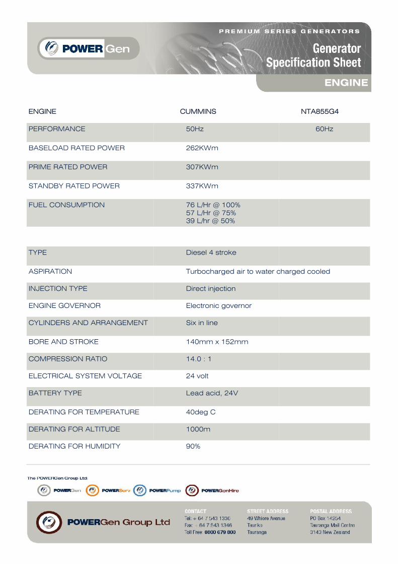
MODEL PG 365 AC Powered by: GENERATING SET PERFORMANCE 50Hz 60Hz VOLTAGE V400 PHASES Three PRIME RATED POWER 365.0kVA STANDBY RATED POWER 400.0kVA POWER FACTOR 0.80 PF FUEL USAGE @ 75% 57 L/phr
programmable protections configurable for any measured value to create customer-specific
Protections.
Analogue meters for Voltmeter , Ammeter (3 phases) , Frequency meter , Hour-meter , Batteryvoltage meter, Analogue gauges for Fuel level .Water Temp, oil Pressure, Battery charging current,Battery voltage.
Gross En gine Power Output - kWm
Litre/h
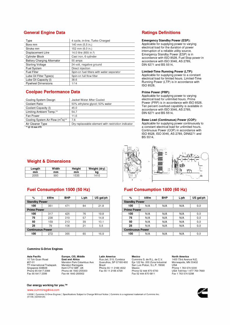
Displacement : 14.0 litre (855 in3 ) Bore : 140 mm (5.5 in.) Stroke : 152 mm (6.0 in.)
No. of Cylinders : 6 Aspiration : Turbocharged and Aftercooled
OUTPUT POWER FUEL CONSUMPTION
% kWm BHPkg/
kWm·hlb/
BHP·hlitre/hour
U.S. Gal/hour
STANDBY POWER
100 351 470 0.203 0.337 84 22.3
PRIME POWER
100 317 425 0.204 0.334 76 20.0
75 238 319 0.204 0.334 57 15.0
50 158 212 0.210 0.342 39 10.2
25 79 106 0.226 0.375 21 5.6
CONTINUOUS POWER
100 272 365 0.204 0.334 65 17.2
CUMMINS ENGINE COMPANY, INC
Columbus, Indiana 47201
ENGINE PERFORMANCE CURVE
Curve Number:
FR-1624Basic Engine Model:
NTA855-G4
Engine Critical Parts List:
CPL: 1436
Date:
8May97
PageNo.
Engine Speed Standby Power Prime Power Continuous Power
RPM kWm BHP kWm BHP kWm BHP
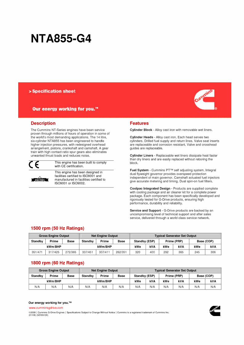
1500 351 470 317 425 272 365
1800 ----- ----- ----- ----- ----- -----
CONVERSIONS: (Litres = U.S. Gal x 3.785) (Engine kWm = BHP x 0.746) (U.S. Gal = Litres x 0.2642) (Engine BHP = Engine kWm x 1.34)
Engine Performance Data @ 1500 RPM
Engine Performance Data @ 1800 RPM
1500 RPM
Data shown above represent gross engine performance capabilities obtained and corrected in accordance with ISO-3046 conditions of 100 kPa (29.53 in Hg)barometric pressure [110 m (361 ft) altitude], 25 °C (77 °F) air inlet temperature, and relative humidity of 30% with No. 2 diesel or a fuel corresponding to ASTM D2.
See reverse side for application rating guidelines.The fuel consumption data is based on No. 2 diesel fuel weight at 0.85 kg/litre (7.1 lbs/U.S. gal).Power output curves are based on the engine operating with fuel system, water pump and lubricating oil pump; not included are battery charging alternator, fan, optional equipment and driven components.
TECHNICAL DATA DEPT. CERTIFIED WITHIN 5% CHIEF ENGINEER
Not Available at 1800 RPMNot Available at 1800 RPM
NTA855-G4
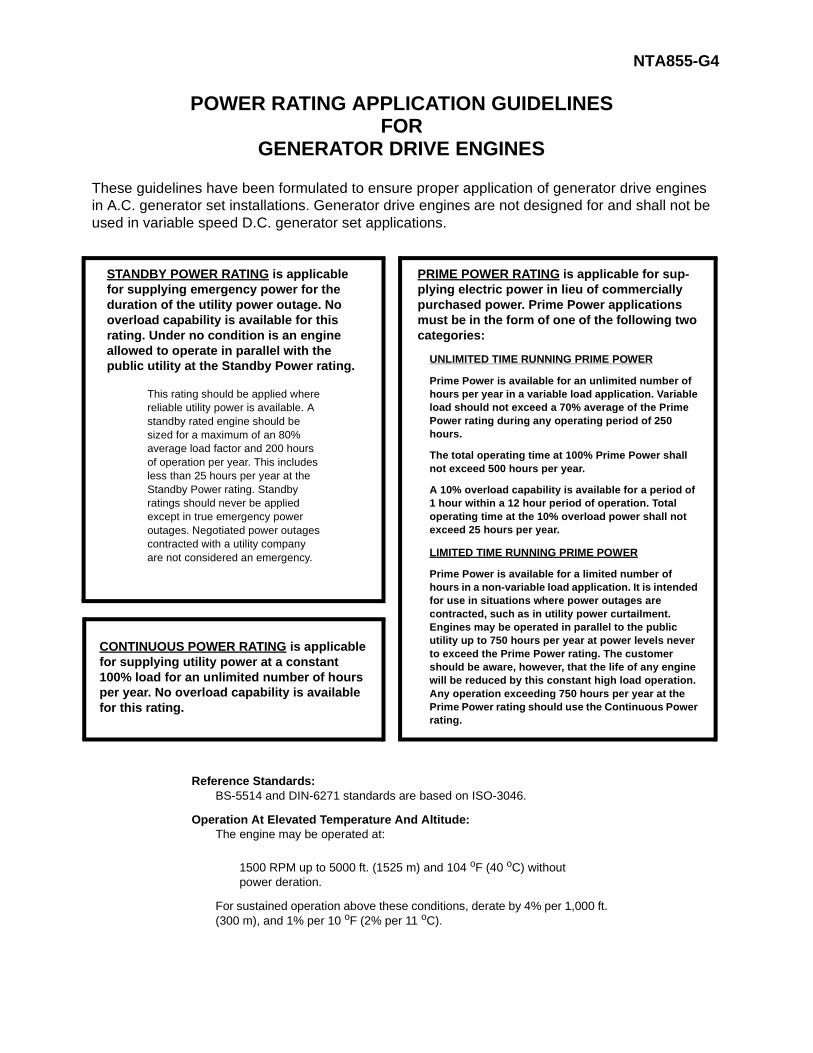
POWER RATING APPLICATION GUIDELINESFOR
GENERATOR DRIVE ENGINES
These guidelines have been formulated to ensure proper application of generator drive engines in A.C. generator set installations. Generator drive engines are not designed for and shall not be used in variable speed D.C. generator set applications.
STANDBY POWER RATING is applicable for supplying emergency power for the duration of the utility power outage. No overload capability is available for this rating. Under no condition is an engine allowed to operate in parallel with the public utility at the Standby Power rating.
This rating should be applied where reliable utility power is available. A standby rated engine should be sized for a maximum of an 80% average load factor and 200 hours of operation per year. This includes less than 25 hours per year at the Standby Power rating. Standby ratings should never be applied except in true emergency power outages. Negotiated power outages contracted with a utility company are not considered an emergency.
PRIME POWER RATING is applicable for sup-plying electric power in lieu of commercially purchased power. Prime Power applications must be in the form of one of the following two categories:
UNLIMITED TIME RUNNING PRIME POWER
Prime Power is available for an unlimited number of hours per year in a variable load application. Variable load should not exceed a 70% average of the Prime Power rating during any operating period of 250 hours.
The total operating time at 100% Prime Power shall not exceed 500 hours per year.
A 10% overload capability is available for a period of 1 hour within a 12 hour period of operation. Total operating time at the 10% overload power shall not exceed 25 hours per year.
LIMITED TIME RUNNING PRIME POWER
Prime Power is available for a limited number of hours in a non-variable load application. It is intended for use in situations where power outages are contracted, such as in utility power curtailment. Engines may be operated in parallel to the public utility up to 750 hours per year at power levels never to exceed the Prime Power rating. The customer should be aware, however, that the life of any engine will be reduced by this constant high load operation. Any operation exceeding 750 hours per year at the Prime Power rating should use the Continuous Power rating.
CONTINUOUS POWER RATING is applicable for supplying utility power at a constant 100% load for an unlimited number of hours per year. No overload capability is available for this rating.
Reference Standards:BS-5514 and DIN-6271 standards are based on ISO-3046.
Operation At Elevated Temperature And Altitude:The engine may be operated at:
1500 RPM up to 5000 ft. (1525 m) and 104 oF (40 oC) without power deration.
For sustained operation above these conditions, derate by 4% per 1,000 ft. (300 m), and 1% per 10 oF (2% per 11 oC).
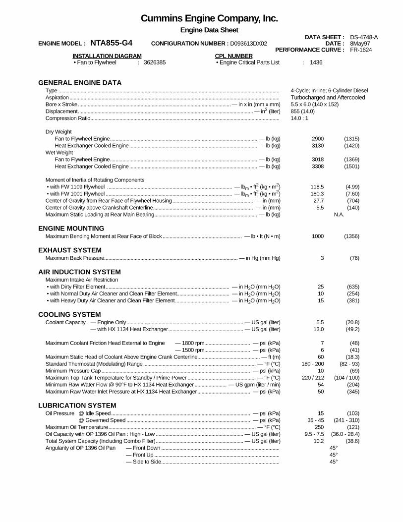
Cummins Engine Company, Inc.Engine Data Sheet
DATA SHEET : DS-4748-AENGINE MODEL : NTA855-G4 CONFIGURATION NUMBER : D093613DX02 DATE : 8May97
PERFORMANCE CURVE : FR-1624INSTALLATION DIAGRAM CPL NUMBER • Fan to Flywheel : 3626385 • Engine Critical Parts List : 1436
GENERAL ENGINE DATAType ............................................................................................................................................................... 4-Cycle; In-line; 6-Cylinder DieselAspiration....................................................................................................................................................... Turbocharged and AftercooledBore x Stroke.............................................................................................................. — in x in (mm x mm) 5.5 x 6.0 (140 x 152)Displacement.............................................................................................................................. — in3
Moment of Inertia of Rotating Components • with FW 1109 Flywheel .......................................................................................... — lbm • ft2 (kg • m2) 118.5 (4.99) • with FW 1001 Flywheel ........................................................................................... — lbm • ft2 (kg • m2) 180.3 (7.60)Center of Gravity from Rear Face of Flywheel Housing.......................................................... — in (mm) 27.7 (704)Center of Gravity above Crankshaft Centerline........................................................................ — in (mm) 5.5 (140)Maximum Static Loading at Rear Main Bearing.......................................................................... — lb (kg) N.A.
ENGINE MOUNTINGMaximum Bending Moment at Rear Face of Block ......................................................... — lb • ft (N • m) 1000 (1356)
EXHAUST SYSTEMMaximum Back Pressure................................................................................................ — in Hg (mm Hg) 3 (76)
AIR INDUCTION SYSTEMMaximum Intake Air Restriction • with Dirty Filter Element......................................................................................... — in H2O (mm H2O) 25 (635) • with Normal Duty Air Cleaner and Clean Filter Element...................................... — in H2O (mm H2O) 10 (254) • with Heavy Duty Air Cleaner and Clean Filter Element....................................... — in H2O (mm H2O) 15 (381)
COOLING SYSTEMCoolant Capacity — Engine Only.................................................................................... — US gal (liter) 5.5 (20.8)
— with HX 1134 Heat Exchanger...................................................... — US gal (liter) 13.0 (49.2)
Maximum Coolant Friction Head External to Engine — 1800 rpm................................. — psi (kPa) 7 (48)— 1500 rpm................................. — psi (kPa) 6 (41)
Maximum Static Head of Coolant Above Engine Crank Centerline............................................. — ft (m) 60 (18.3)Standard Thermostat (Modulating) Range................................................................................. — °F (°C) 180 - 200 (82 - 93)Minimum Pressure Cap........................................................................................................... — psi (kPa) 10 (69)Maximum Top Tank Temperature for Standby / Prime Power ................................................. — °F (°C) 220 / 212 (104 / 100)Minimum Raw Water Flow @ 90°F to HX 1134 Heat Exchanger ....................... — US gpm (liter / min) 54 (204)Maximum Raw Water Inlet Pressure at HX 1134 Heat Exchanger...................................... — psi (kPa) 50 (345)
@ Governed Speed ......................................................................................... — psi (kPa) 35 - 45 (241 - 310)Maximum Oil Temperature.......................................................................................................... — °F (°C) 250 (121)Oil Capacity with OP 1396 Oil Pan : High - Low ............................................................... — US gal (liter) 9.5 - 7.5 (36.0 - 28.4)Total System Capacity (Including Combo Filter)............................................................... — US gal (liter) 10.2 (38.6)Angularity of OP 1396 Oil Pan — Front Down ..................................................................................... 45°
— Front Up .......................................................................................... 45°— Side to Side..................................................................................... 45°
FUEL SYSTEMType Injection System...................................................................................................................................................................... Direct Injection Cummins PTMaximum Restriction at PT Fuel Injection Pump — with Clean Fuel Filter.................................................... — in Hg (mm Hg) 4.0 (102)
— with Dirty Fuel Filter .................................................... — in Hg (mm Hg) 8.0 (203)Maximum Allowable Head on Injector Return Line (Consisting of Friction Head and Static Head).............. — in Hg (mm Hg) 6.0 (152)Maximum Fuel Flow to Injection Pump......................................................................................................... — US gph (liter / hr) 99 (375)
ELECTRICAL SYSTEMCranking Motor (Heavy Duty, Positive Engagement)......................................................................................................... — volt 24Battery Charging System, Negative Ground............................................................................................................... — ampere 35Maximum Allowable Resistance of Cranking Circuit......................................................................................................... — ohm 0.002Minimum Recommended Battery Capacity
• Cold Soak @ 50 °F (10 °C) and Above............................................................................................................. — 0°F CCA 600• Cold Soak @ 32 °F to 50 °F (0 °C to 10 °C)...................................................................................................... — 0°F CCA 640• Cold Soak @ 0 °F to 32 °F (-18 °C to 0 °C)....................................................................................................... — 0°F CCA 900
COLD START CAPABILITYMinimum Ambient Temperature for Aided (with Coolant Heater) Cold Start within 10 seconds ............................... — °F (°C) 50 (10)Minimum Ambient Temperature for Unaided Cold Start............................................................................................... — °F (°C) 20 (-7)
PERFORMANCE DATAAll data is based on: • Engine operating with fuel system, water pump, lubricating oil pump, air cleaner and exhaust
silencer; not included are battery charging alternator, fan, and optional driven components.• Engine operating with fuel corresponding to grade No. 2-D per ASTM D975.• ISO 3046, Part 1, Standard Reference Conditions of:
Barometric Pressure : 100 kPa (29.53 in Hg) Air Temperature : 25 °C (77 °F)Altitude : 110 m (361 ft) Relative Humidity : 30%
Steady State Stability Band at any Constant Load .............................................................................................................. — % +/- 0.25Estimated Free Field Sound Pressure Level of a Typical Generator Set;
Excludes Exhaust Noise; at Rated Load and 7.5 m (24.6 ft); 1500 rpm................................................................. — dBA 89Exhaust Sound Pressure at 1 m and 45° from Exhaust Outlet........................................................................................ — dBA 120
STANDBY POWER PRIME POWER60 hz 50 hz 60 hz 50 hz
Governed Engine Speed..............................................................— rpm 1500 1500Engine Idle Speed ....................................................................... — rpm 575 - 675 575 - 675Gross Engine Power Output...........................................— BHP (kWm) 470 (350) 425 (317)Brake Mean Effective Pressure...........................................— psi (kPa) 290 (1999) 262 (1806)Piston Speed.................................................................— ft / min (m / s) 1500 (7.6) 1500 (7.6)Friction Horsepower ......................................................... — HP (kWm) 30 (22) 30 (22)Engine Water Flow at Stated Friction Head External to Engine:
• 2 psi Friction Head (estimated)....................... — US gpm (liter / s) 105 (6.6) 105 (6.6)• Maximum Friction Head (estimated).............. — US gpm (liter / s) 94 (5.9) 94 (5.9)
Engine Data with Dry Type Exhaust ManifoldIntake Air Flow ................................................................— cfm (liter / s) 920 (434) 865 (408)Exhaust Gas Temperature......................................................— °F (°C) 1005 (541) 975 (524)Exhaust Gas Flow ..........................................................— cfm (liter / s) 2595 (1225) 2390 (1128)Air to Fuel Ratio ..................................................................... — air : fuel 22.4 : 1 24.3 : 1Radiated Heat to Ambient .....................................— BTU / min (kWm) 2895 (51) 2600 (46)Heat Rejection to Coolant ......................................— BTU / min (kWm) 11750 (206) 10625 (187)Heat Rejection to Exhaust .....................................— BTU / min (kWm) 13700 (241) 12050 (212)
ENGINE MODEL : NTA855-G4DATA SHEET : DS-4748-A
DATE : 8May97CUMMINS ENGINE COMPANY, INC. Columbus, Indiana 47202-3005 CURVE NO. : FR-1624
NotAvailable
at1800 RPM
(60 hz)
NotAvailable
at1800 RPM
(60 hz)
N.A. - Data is Not AvailableN/A - Not Applicable to this EngineTBD - To Be Determined
HCI 434E/444E - Technical Data Sheet
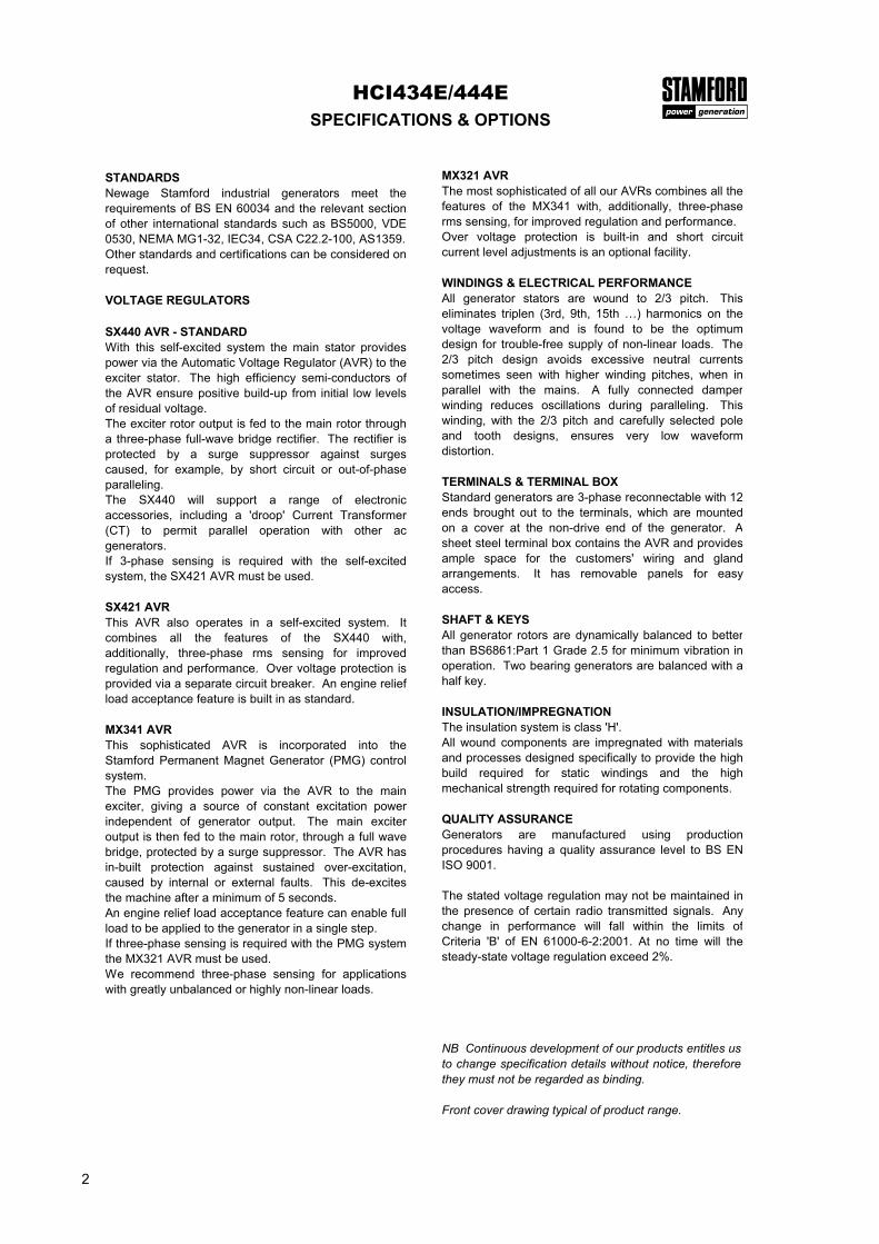
HCI434E/444ESPECIFICATIONS & OPTIONS
STANDARDSNewage Stamford industrial generators meet therequirements of BS EN 60034 and the relevant sectionof other international standards such as BS5000, VDE0530, NEMA MG1-32, IEC34, CSA C22.2-100, AS1359.Other standards and certifications can be considered onrequest.
VOLTAGE REGULATORS
SX440 AVR - STANDARDWith this self-excited system the main stator providespower via the Automatic Voltage Regulator (AVR) to theexciter stator. The high efficiency semi-conductors ofthe AVR ensure positive build-up from initial low levelsof residual voltage.The exciter rotor output is fed to the main rotor througha three-phase full-wave bridge rectifier. The rectifier isprotected by a surge suppressor against surgescaused, for example, by short circuit or out-of-phaseparalleling.The SX440 will support a range of electronicaccessories, including a 'droop' Current Transformer(CT) to permit parallel operation with other acgenerators.If 3-phase sensing is required with the self-excitedsystem, the SX421 AVR must be used.
SX421 AVRThis AVR also operates in a self-excited system. Itcombines all the features of the SX440 with,additionally, three-phase rms sensing for improvedregulation and performance. Over voltage protection isprovided via a separate circuit breaker. An engine reliefload acceptance feature is built in as standard.
MX341 AVRThis sophisticated AVR is incorporated into theStamford Permanent Magnet Generator (PMG) controlsystem.The PMG provides power via the AVR to the mainexciter, giving a source of constant excitation powerindependent of generator output. The main exciteroutput is then fed to the main rotor, through a full wavebridge, protected by a surge suppressor. The AVR hasin-built protection against sustained over-excitation,caused by internal or external faults. This de-excitesthe machine after a minimum of 5 seconds.An engine relief load acceptance feature can enable fullload to be applied to the generator in a single step.If three-phase sensing is required with the PMG systemthe MX321 AVR must be used.We recommend three-phase sensing for applicationswith greatly unbalanced or highly non-linear loads.
MX321 AVRThe most sophisticated of all our AVRs combines all thefeatures of the MX341 with, additionally, three-phaserms sensing, for improved regulation and performance.Over voltage protection is built-in and short circuitcurrent level adjustments is an optional facility.
WINDINGS & ELECTRICAL PERFORMANCEAll generator stators are wound to 2/3 pitch. Thiseliminates triplen (3rd, 9th, 15th …) harmonics on thevoltage waveform and is found to be the optimumdesign for trouble-free supply of non-linear loads. The2/3 pitch design avoids excessive neutral currentssometimes seen with higher winding pitches, when inparallel with the mains. A fully connected damperwinding reduces oscillations during paralleling. Thiswinding, with the 2/3 pitch and carefully selected poleand tooth designs, ensures very low waveformdistortion.
TERMINALS & TERMINAL BOXStandard generators are 3-phase reconnectable with 12ends brought out to the terminals, which are mountedon a cover at the non-drive end of the generator. Asheet steel terminal box contains the AVR and providesample space for the customers' wiring and glandarrangements. It has removable panels for easyaccess.
SHAFT & KEYSAll generator rotors are dynamically balanced to betterthan BS6861:Part 1 Grade 2.5 for minimum vibration inoperation. Two bearing generators are balanced with ahalf key.
INSULATION/IMPREGNATIONThe insulation system is class 'H'.All wound components are impregnated with materialsand processes designed specifically to provide the highbuild required for static windings and the highmechanical strength required for rotating components.
QUALITY ASSURANCEGenerators are manufactured using productionprocedures having a quality assurance level to BS ENISO 9001.
The stated voltage regulation may not be maintained inthe presence of certain radio transmitted signals. Anychange in performance will fall within the limits ofCriteria 'B' of EN 61000-6-2:2001. At no time will thesteady-state voltage regulation exceed 2%.
NB Continuous development of our products entitles usto change specification details without notice, thereforethey must not be regarded as binding.
Front cover drawing typical of product range.
2
CONTROL SYSTEM SEPARATELY EXCITED BY P.M.G.
A.V.R. MX321 MX341
VOLTAGE REGULATION ± 0.5 % ± 1.0 % With 4% ENGINE GOVERNING
SUSTAINED SHORT CIRCUIT
CONTROL SYSTEM SELF EXCITED
A.V.R. SX440 SX421
VOLTAGE REGULATION ± 1.0 % ± 0.5 % With 4% ENGINE GOVERNING
SUSTAINED SHORT CIRCUIT WILL NOT SUSTAIN A SHORT CIRCUIT
INSULATION SYSTEM CLASS H
PROTECTION
RATED POWER FACTOR
STATOR WINDING
WINDING PITCH
WINDING LEADS
STATOR WDG. RESISTANCE
ROTOR WDG. RESISTANCE
EXCITER STATOR RESISTANCE
EXCITER ROTOR RESISTANCE
R.F.I. SUPPRESSION BS EN 61000-6-2 & BS EN 61000-6-4,VDE 0875G, VDE 0875N. refer to factory for others
WAVEFORM DISTORTION NO LOAD < 1.5% NON-DISTORTING BALANCED LINEAR LOAD < 5.0%
MAXIMUM OVERSPEED
BEARING DRIVE END
BEARING NON-DRIVE END
WEIGHT COMP. GENERATOR
WEIGHT WOUND STATOR
WEIGHT WOUND ROTOR
WR² INERTIA
SHIPPING WEIGHTS in a crate
PACKING CRATE SIZE
TELEPHONE INTERFERENCE
COOLING AIR
VOLTAGE SERIES STAR 380/220 400/231 415/240 440/254 416/240 440/254 460/266 480/277
VOLTAGE PARALLEL STAR 190/110 200/115 208/120 220/127 208/120 220/127 230/133 240/138
VOLTAGE SERIES DELTA 220/110 230/115 240/120 254/127 240/120 254/127 266/133 277/138kVA BASE RATING FOR REACTANCE VALUES
REACTANCES ARE SATURATED VALUES ARE PER UNIT AT RATING AND VOLTAGE INDICATEDT'd TRANSIENT TIME CONST.T''d SUB-TRANSTIME CONST.T'do O.C. FIELD TIME CONST.Ta ARMATURE TIME CONST.
SHORT CIRCUIT RATIO
18 Ohms at 22°C
0.068 Ohms PER PHASE AT 22°C
1100 kg
156 x 87 x 107(cm)
1095 kg
155 x 87 x 107(cm)
1 BEARING 2 BEARING
2250 Rev/Min
470 kg
HCI434E/444E
0.8 m³/sec 1700 cfm 0.99 m³/sec 2100 cfm
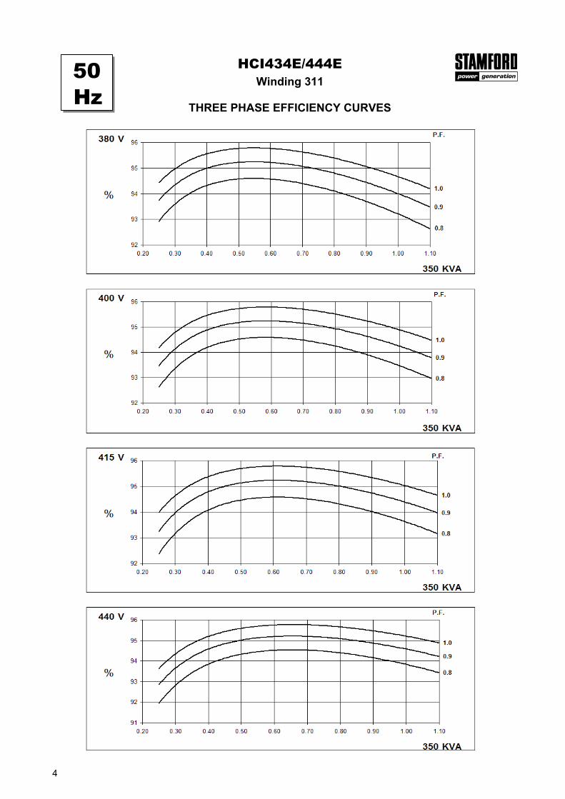
50 Hz
THF<2%
60 Hz
TIF<50
377 kg
4.4343 kgm2
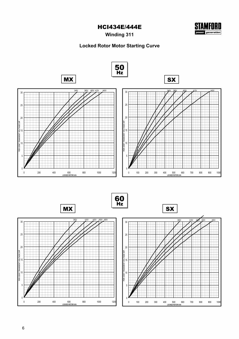
WINDING 311
400 kg
4.6331 kgm2
IP23
0.8
DOUBLE LAYER LAP
TWO THIRDS
12
1030 kg1024 kg
470 kg
REFER TO SHORT CIRCUIT DECREMENT CURVES (page 7)
BALL. 6314 (ISO)
1/Xd
0.08s0.019s1.7s
0.018s
1.19 Ohms at 22°C
0.009 Ohms PER PHASE AT 22°C SERIES STAR CONNECTED
3-phase 2-phase L-L 1-phase L-NVoltage Factor Voltage Factor x 1.00 x 0.87 x 1.30
380v X 1.00 416v X 1.00 x 1.00 x 1.80 x 3.20400v X 1.05 440v X 1.06 x 1.00 x 1.50 x 2.50415v X 1.10 460v X 1.10 10 sec. 5 sec. 2 sec.440v X 1.16 480v X 1.15
The sustained current value is constant irrespectiveof voltage level
Three-phase Short Circuit Decrement Curve. No-load Excitation at Rated SpeedBased on star (wye) connection.
Max. sustained durationAll other times are unchanged
Instantaneous
SustainedMinimum
HCI434E/444E
50Hz 60Hz
Sustained Short Circuit = 1,500 Amps
Sustained Short Circuit = 1,600 AmpsNote 1The following multiplication factors should beused to adjust the values from curve betweentime 0.001 seconds and the minimum currentpoint in respect of nominal operating voltage :
Note 2The following multiplication factor should be used to convert thevalues calculated in accordance with NOTE 1 to those applicableto the various types of short circuit :
Note 3Curves are drawn for Star (Wye) connected machines. For otherconnection the following multipliers should be applied to currentvalues as shown : Parallel Star = Curve current value X 2Series Delta = Curve current value X 1.732
50Hz
60Hz
100
1000
10000
0.001 0.01 0.1 1 10TIME (secs)
CU
RR
EN
T (A
mps
)
SYMMETRICAL
ASYMMETRICAL
100
1000
10000
0.001 0.01 0.1 1 10TIME (secs)
CU
RR
EN
T (A
mps
)
SYMMETRICAL
ASYMMETRICAL
7
Class - Temp Rise
Series Star (V) 380 400 415 440 380 400 415 440 380 400 415 440 380 400 415 440