+ All Categories
Home > Documents > Model Predictive Control of STATCOM for Grid Voltage ...

Model Predictive Control of STATCOM for Grid Voltage ...

Date post: 28-Feb-2022
Category:
Upload: others
View: 3 times
Download: 0 times
Share this document with a friend
6
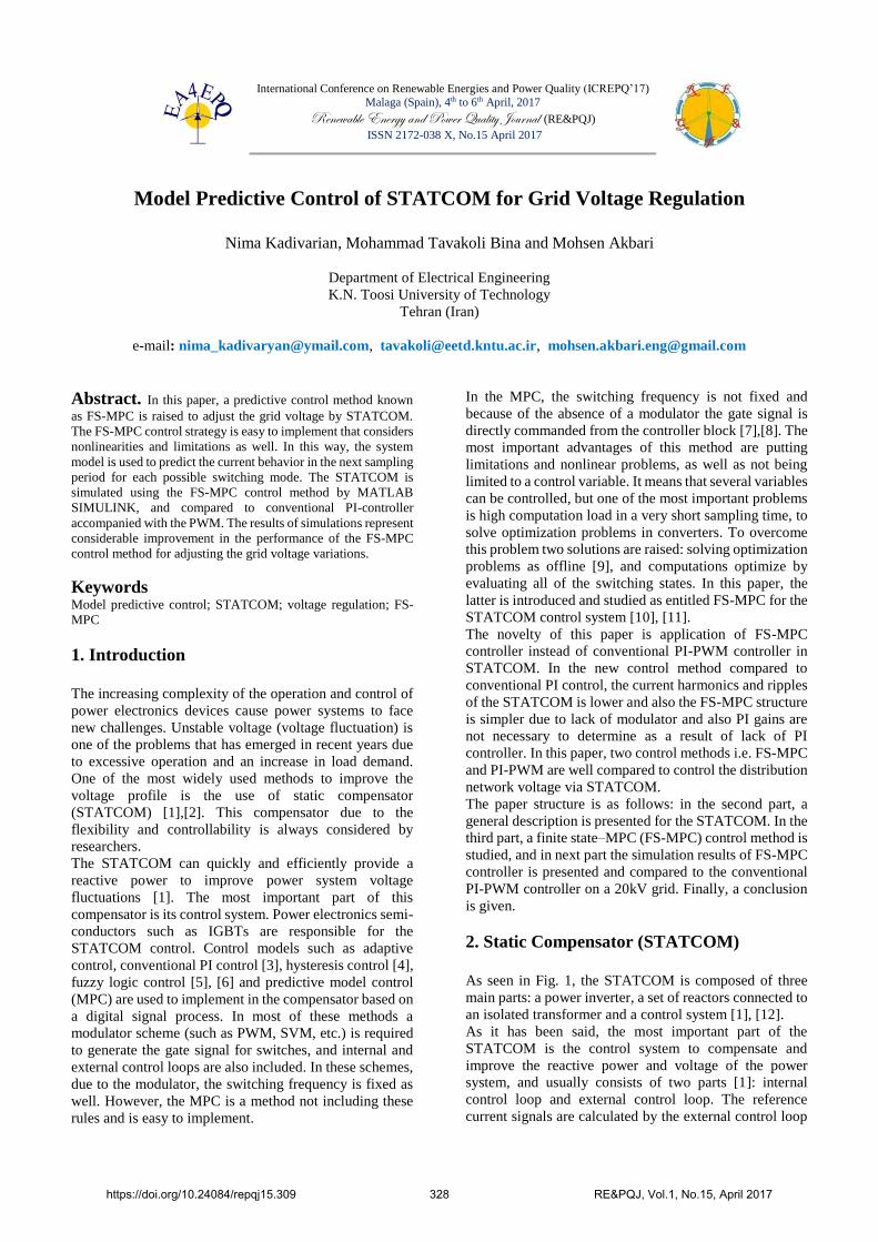
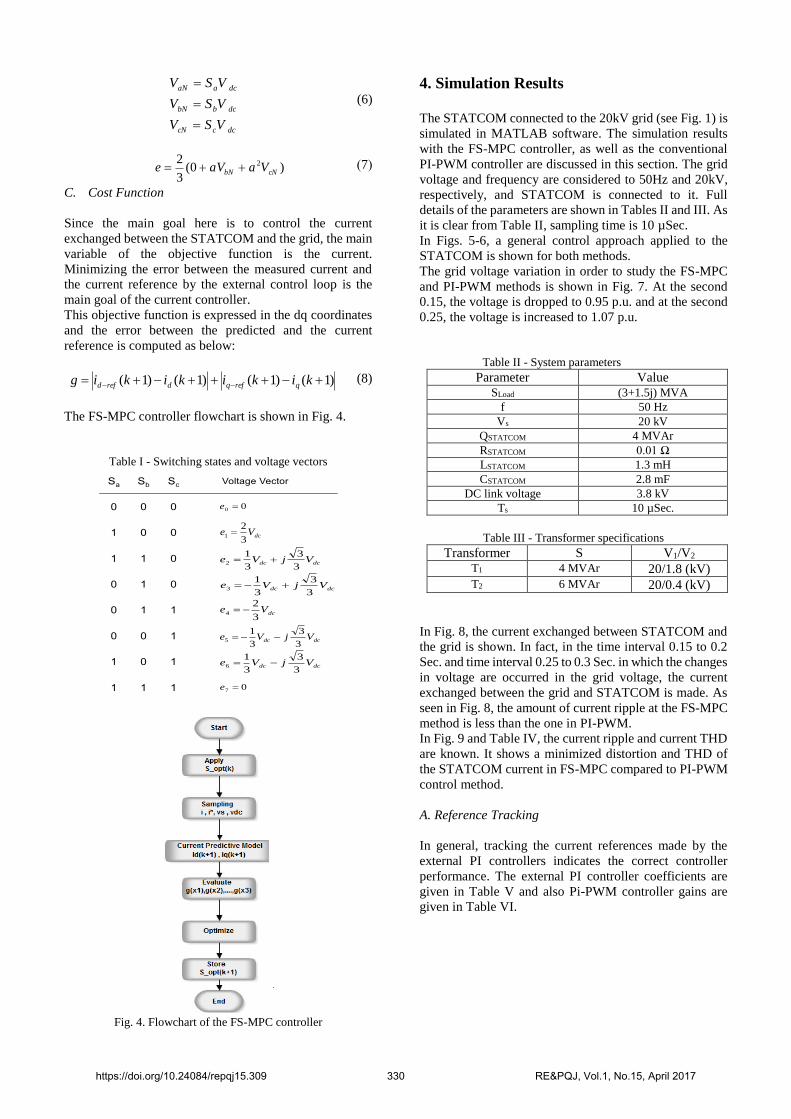
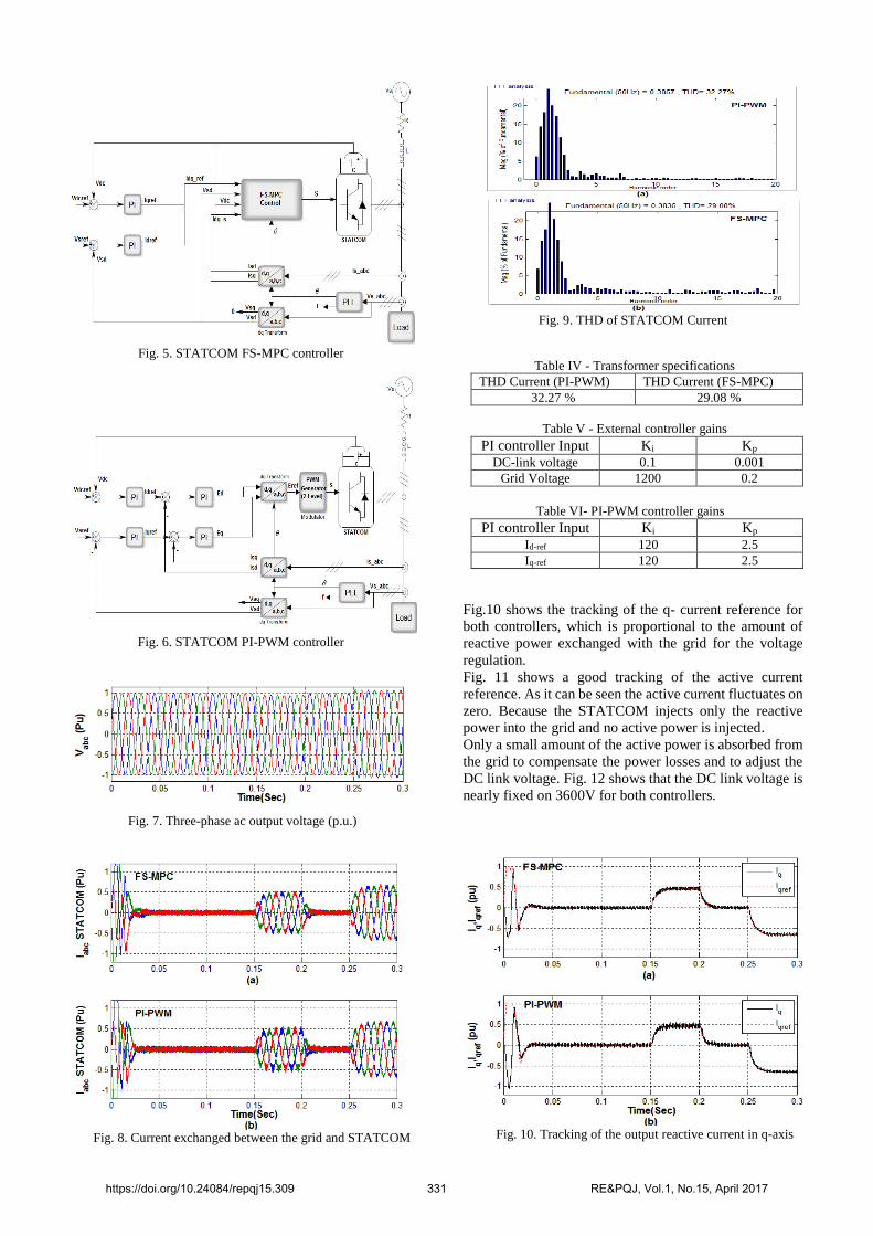
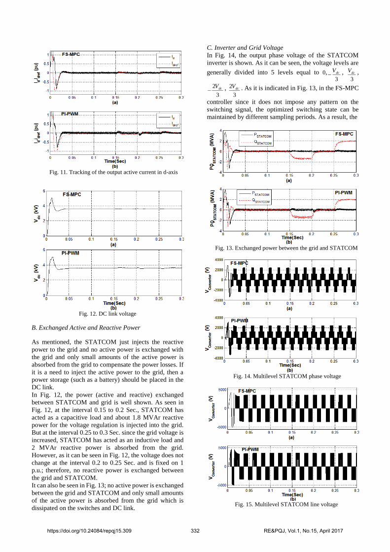
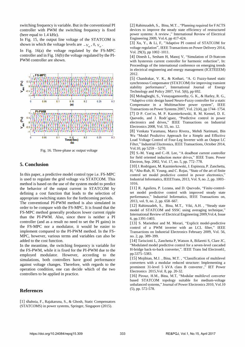
International Conference on Renewable Energies and Power Quality (ICREPQ’17) Malaga (Spain), 4 th to 6 th April, 2017 Renewable Energy and Power Quality Journal (RE&PQJ) ISSN 2172-038 X, No.15 April 2017 Model Predictive Control of STATCOM for Grid Voltage Regulation Nima Kadivarian, Mohammad Tavakoli Bina and Mohsen Akbari Department of Electrical Engineering K.N. Toosi University of Technology Tehran (Iran) e-mail: [email protected], [email protected], [email protected] Abstract. In this paper, a predictive control method known as FS-MPC is raised to adjust the grid voltage by STATCOM. The FS-MPC control strategy is easy to implement that considers nonlinearities and limitations as well. In this way, the system model is used to predict the current behavior in the next sampling period for each possible switching mode. The STATCOM is simulated using the FS-MPC control method by MATLAB SIMULINK, and compared to conventional PI-controller accompanied with the PWM. The results of simulations represent considerable improvement in the performance of the FS-MPC control method for adjusting the grid voltage variations. Keywords Model predictive control; STATCOM; voltage regulation; FS- MPC 1. Introduction The increasing complexity of the operation and control of power electronics devices cause power systems to face new challenges. Unstable voltage (voltage fluctuation) is one of the problems that has emerged in recent years due to excessive operation and an increase in load demand. One of the most widely used methods to improve the voltage profile is the use of static compensator (STATCOM) [1],[2]. This compensator due to the flexibility and controllability is always considered by researchers. The STATCOM can quickly and efficiently provide a reactive power to improve power system voltage fluctuations [1]. The most important part of this compensator is its control system. Power electronics semi- conductors such as IGBTs are responsible for the STATCOM control. Control models such as adaptive control, conventional PI control [3], hysteresis control [4], fuzzy logic control [5], [6] and predictive model control (MPC) are used to implement in the compensator based on a digital signal process. In most of these methods a modulator scheme (such as PWM, SVM, etc.) is required to generate the gate signal for switches, and internal and external control loops are also included. In these schemes, due to the modulator, the switching frequency is fixed as well. However, the MPC is a method not including these rules and is easy to implement. In the MPC, the switching frequency is not fixed and because of the absence of a modulator the gate signal is directly commanded from the controller block [7],[8]. The most important advantages of this method are putting limitations and nonlinear problems, as well as not being limited to a control variable. It means that several variables can be controlled, but one of the most important problems is high computation load in a very short sampling time, to solve optimization problems in converters. To overcome this problem two solutions are raised: solving optimization problems as offline [9], and computations optimize by evaluating all of the switching states. In this paper, the latter is introduced and studied as entitled FS-MPC for the STATCOM control system [10], [11]. The novelty of this paper is application of FS-MPC controller instead of conventional PI-PWM controller in STATCOM. In the new control method compared to conventional PI control, the current harmonics and ripples of the STATCOM is lower and also the FS-MPC structure is simpler due to lack of modulator and also PI gains are not necessary to determine as a result of lack of PI controller. In this paper, two control methods i.e. FS-MPC and PI-PWM are well compared to control the distribution network voltage via STATCOM. The paper structure is as follows: in the second part, a general description is presented for the STATCOM. In the third part, a finite stateMPC (FS-MPC) control method is studied, and in next part the simulation results of FS-MPC controller is presented and compared to the conventional PI-PWM controller on a 20kV grid. Finally, a conclusion is given. 2. Static Compensator (STATCOM) As seen in Fig. 1, the STATCOM is composed of three main parts: a power inverter, a set of reactors connected to an isolated transformer and a control system [1], [12]. As it has been said, the most important part of the STATCOM is the control system to compensate and improve the reactive power and voltage of the power system, and usually consists of two parts [1]: internal control loop and external control loop. The reference current signals are calculated by the external control loop https://doi.org/10.24084/repqj15.309 328 RE&PQJ, Vol.1, No.15, April 2017
Transcript

International Conference on Renewable Energies and Power Quality (ICREPQ’17)

Malaga (Spain), 4th to 6th April, 2017 Renewable Energy and Power Quality Journal (RE&PQJ)

ISSN 2172-038 X, No.15 April 2017

Model Predictive Control of STATCOM for Grid Voltage Regulation

Nima Kadivarian, Mohammad Tavakoli Bina and Mohsen Akbari

Department of Electrical Engineering

K.N. Toosi University of Technology

Tehran (Iran)

e-mail: [email protected], [email protected], [email protected]

Abstract. In this paper, a predictive control method known

as FS-MPC is raised to adjust the grid voltage by STATCOM.

The FS-MPC control strategy is easy to implement that considers

nonlinearities and limitations as well. In this way, the system

model is used to predict the current behavior in the next sampling

period for each possible switching mode. The STATCOM is

simulated using the FS-MPC control method by MATLAB

SIMULINK, and compared to conventional PI-controller

accompanied with the PWM. The results of simulations represent

considerable improvement in the performance of the FS-MPC

control method for adjusting the grid voltage variations.

Keywords Model predictive control; STATCOM; voltage regulation; FS-

MPC

1. Introduction

The increasing complexity of the operation and control of

power electronics devices cause power systems to face

new challenges. Unstable voltage (voltage fluctuation) is

one of the problems that has emerged in recent years due

to excessive operation and an increase in load demand.

One of the most widely used methods to improve the

voltage profile is the use of static compensator

(STATCOM) [1],[2]. This compensator due to the

flexibility and controllability is always considered by

researchers.

The STATCOM can quickly and efficiently provide a

reactive power to improve power system voltage

fluctuations [1]. The most important part of this

compensator is its control system. Power electronics semi-

conductors such as IGBTs are responsible for the

STATCOM control. Control models such as adaptive

control, conventional PI control [3], hysteresis control [4],

fuzzy logic control [5], [6] and predictive model control

(MPC) are used to implement in the compensator based on

a digital signal process. In most of these methods a

modulator scheme (such as PWM, SVM, etc.) is required

to generate the gate signal for switches, and internal and

external control loops are also included. In these schemes,

due to the modulator, the switching frequency is fixed as

well. However, the MPC is a method not including these

rules and is easy to implement.

In the MPC, the switching frequency is not fixed and

because of the absence of a modulator the gate signal is

directly commanded from the controller block [7],[8]. The

most important advantages of this method are putting

limitations and nonlinear problems, as well as not being

limited to a control variable. It means that several variables

can be controlled, but one of the most important problems

is high computation load in a very short sampling time, to

solve optimization problems in converters. To overcome

this problem two solutions are raised: solving optimization

problems as offline [9], and computations optimize by

evaluating all of the switching states. In this paper, the

latter is introduced and studied as entitled FS-MPC for the

STATCOM control system [10], [11].

The novelty of this paper is application of FS-MPC

controller instead of conventional PI-PWM controller in

STATCOM. In the new control method compared to

conventional PI control, the current harmonics and ripples

of the STATCOM is lower and also the FS-MPC structure

is simpler due to lack of modulator and also PI gains are

not necessary to determine as a result of lack of PI

controller. In this paper, two control methods i.e. FS-MPC

and PI-PWM are well compared to control the distribution

network voltage via STATCOM.

The paper structure is as follows: in the second part, a

general description is presented for the STATCOM. In the

third part, a finite state–MPC (FS-MPC) control method is

studied, and in next part the simulation results of FS-MPC

controller is presented and compared to the conventional

PI-PWM controller on a 20kV grid. Finally, a conclusion

is given.

2. Static Compensator (STATCOM)

As seen in Fig. 1, the STATCOM is composed of three

main parts: a power inverter, a set of reactors connected to

an isolated transformer and a control system [1], [12].

As it has been said, the most important part of the

STATCOM is the control system to compensate and

improve the reactive power and voltage of the power

system, and usually consists of two parts [1]: internal

control loop and external control loop. The reference

current signals are calculated by the external control loop

https://doi.org/10.24084/repqj15.309 328 RE&PQJ, Vol.1, No.15, April 2017

with the desired target. The reference currents are

generated using the PI control loops as shown in Fig. 2.

Fig. 1. Static synchronous compensator (STATCOM)

Fig. 2. External control loops

Internal controller or current controller tracks the current

references calculated by the external controller. The

current controller is the most basic part in the control unit.

If the correct operation of the current controller is satisfied,

then the grid voltage regulation can be paid. Indeed, this

controller part tracks the current references in the fastest

time and with zero permanent error. In this paper, a new

predictive control method so called FS-MPC for the

internal controller is used [13], [14].

3. FS-MPC Controller

The predictive control approach is based on the principle

that only a limited number of switching modes may be

caused by the converter and the system model can be used

to predict the variables for each switching mode. To select

an appropriate switching mode, an objective function

should be defined [10],[11].All predicted current values of

possible switching modes will be evaluated by the

objective function and an appropriate switching mode that

minimizes the objective function will be selected [7].

A. System Model

Equations for the dynamics of STATCOM current shown

in Fig. 3 can be written in the form of equation (1) for each

phase:

c

b

a

c

b

a

c

b

a

c

b

a

v

v

v

i

i

i

dt

dL

i

i

i

R

E

E

E

.. (1)

The R and L are resistance and leakage inductance for both

filter and isolated transformer. va,b,c represents the grid

phase voltage, Ea,b,c is the STATCOM inverter output

voltage and ia,b,c is the current vector.

Fig. 3. Schematic diagram of a grid-connected inverter

Using the dq0-transform, the equations of three-phase

current is written in the dq frame:

qq

ddb

q

d

b

b

q

d

vE

vE

L

w

I

I

L

Rww

wL

Rw

dt

dIdt

dI

. (2)

where, w and bw are the angular velocity and nominal

velocity, respectively.

Now, using a leader Euler approximation for the derivative

of the current dt

di as shown in (3), equation (2) can be

converted to a discrete-time model in the form of (4) to

predict the current value:

sT

kiki

dt

di )()1( (3)

dqqb

qb

q

qddb

db

d

wTIEvL

TwI

L

RTwkI

wTIEvL

TwI

L

RTwkI

)()1()1(

)()1()1( (4)

B. Inverter Model

The power circuit of the STATCOM inverter is shown in

Fig. 3. The switching modes of the power switches Sa, Sb

and Sc can be zero or one. All of the possible modes

together with the output voltage is obtained according to

(6) -(7) and shown in Table I. In some previous papers,

multilevel converters were proposed because of higher

reliability and lower output harmonics [15],[16].

0

1

0

1

0

1

c

b

a

S

S

S

(5)

https://doi.org/10.24084/repqj15.309 329 RE&PQJ, Vol.1, No.15, April 2017

dcccN

dcbbN

dcaaN

VSV

VSV

VSV

(6)

(7 ) )0(3

2 2

cNbN VaaVe

C. Cost Function

Since the main goal here is to control the current

exchanged between the STATCOM and the grid, the main

variable of the objective function is the current.

Minimizing the error between the measured current and

the current reference by the external control loop is the

main goal of the current controller.

This objective function is expressed in the dq coordinates

and the error between the predicted and the current

reference is computed as below:

)1()1()1()1( kikikikig qrefqdrefd (8)

The FS-MPC controller flowchart is shown in Fig. 4.

Table I - Switching states and voltage vectors

dcdc VjVe

3

3

3

12

00 e

dcdc VjVe

3

3

3

13

dcVe

3

21

dcVe

3

24

dcdc VjVe

3

3

3

15

dcdc VjVe

3

3

3

16

07 e

Fig. 4. Flowchart of the FS-MPC controller

4. Simulation Results

The STATCOM connected to the 20kV grid (see Fig. 1) is

simulated in MATLAB software. The simulation results

with the FS-MPC controller, as well as the conventional

PI-PWM controller are discussed in this section. The grid

voltage and frequency are considered to 50Hz and 20kV,

respectively, and STATCOM is connected to it. Full

details of the parameters are shown in Tables II and III. As

it is clear from Table II, sampling time is 10 µSec.

In Figs. 5-6, a general control approach applied to the

STATCOM is shown for both methods.

The grid voltage variation in order to study the FS-MPC

and PI-PWM methods is shown in Fig. 7. At the second

0.15, the voltage is dropped to 0.95 p.u. and at the second

0.25, the voltage is increased to 1.07 p.u.

Table II - System parameters

Parameter Value SLoad (3+1.5j) MVA

f 50 Hz

Vs 20 kV

QSTATCOM 4 MVAr

RSTATCOM 0.01 Ω

LSTATCOM 1.3 mH

CSTATCOM 2.8 mF

DC link voltage 3.8 kV

Ts 10 µSec.

Table III - Transformer specifications

Transformer S V1/V2

T1 4 MVAr 20/1.8 (kV) T2 6 MVAr 20/0.4 (kV)

In Fig. 8, the current exchanged between STATCOM and

the grid is shown. In fact, in the time interval 0.15 to 0.2

Sec. and time interval 0.25 to 0.3 Sec. in which the changes

in voltage are occurred in the grid voltage, the current

exchanged between the grid and STATCOM is made. As

seen in Fig. 8, the amount of current ripple at the FS-MPC

method is less than the one in PI-PWM.

In Fig. 9 and Table IV, the current ripple and current THD

are known. It shows a minimized distortion and THD of

the STATCOM current in FS-MPC compared to PI-PWM

control method.

A. Reference Tracking

In general, tracking the current references made by the

external PI controllers indicates the correct controller

performance. The external PI controller coefficients are

given in Table V and also Pi-PWM controller gains are

given in Table VI.

https://doi.org/10.24084/repqj15.309 330 RE&PQJ, Vol.1, No.15, April 2017

Fig. 5. STATCOM FS-MPC controller

Fig. 6. STATCOM PI-PWM controller

Fig. 7. Three-phase ac output voltage (p.u.)

Fig. 8. Current exchanged between the grid and STATCOM

Fig. 9. THD of STATCOM Current

Table IV - Transformer specifications

THD Current (PI-PWM) THD Current (FS-MPC)

32.27 % 29.08 %

Table V - External controller gains

PI controller Input Ki Kp

DC-link voltage 0.1 0.001 Grid Voltage 1200 0.2

Table VI- PI-PWM controller gains

PI controller Input Ki Kp

Id-ref 120 2.5 Iq-ref 120 2.5

Fig.10 shows the tracking of the q- current reference for

both controllers, which is proportional to the amount of

reactive power exchanged with the grid for the voltage

regulation.

Fig. 11 shows a good tracking of the active current

reference. As it can be seen the active current fluctuates on

zero. Because the STATCOM injects only the reactive

power into the grid and no active power is injected.

Only a small amount of the active power is absorbed from

the grid to compensate the power losses and to adjust the

DC link voltage. Fig. 12 shows that the DC link voltage is

nearly fixed on 3600V for both controllers.

Fig. 10. Tracking of the output reactive current in q-axis

https://doi.org/10.24084/repqj15.309 331 RE&PQJ, Vol.1, No.15, April 2017

Fig. 11. Tracking of the output active current in d-axis

Fig. 12. DC link voltage

B. Exchanged Active and Reactive Power

As mentioned, the STATCOM just injects the reactive

power to the grid and no active power is exchanged with

the grid and only small amounts of the active power is

absorbed from the grid to compensate the power losses. If

it is a need to inject the active power to the grid, then a

power storage (such as a battery) should be placed in the

DC link.

In Fig. 12, the power (active and reactive) exchanged

between STATCOM and grid is well shown. As seen in

Fig. 12, at the interval 0.15 to 0.2 Sec., STATCOM has

acted as a capacitive load and about 1.8 MVAr reactive

power for the voltage regulation is injected into the grid.

But at the interval 0.25 to 0.3 Sec. since the grid voltage is

increased, STATCOM has acted as an inductive load and

2 MVAr reactive power is absorbed from the grid.

However, as it can be seen in Fig. 12, the voltage does not

change at the interval 0.2 to 0.25 Sec. and is fixed on 1

p.u.; therefore, no reactive power is exchanged between

the grid and STATCOM.

It can also be seen in Fig. 13; no active power is exchanged

between the grid and STATCOM and only small amounts

of the active power is absorbed from the grid which is

dissipated on the switches and DC link.

C. Inverter and Grid Voltage

In Fig. 14, the output phase voltage of the STATCOM

inverter is shown. As it can be seen, the voltage levels are

generally divided into 5 levels equal to 0,3

dcV ,

3

dcV ,

3

2 dcV ,

3

2 dcV . As it is indicated in Fig. 13, in the FS-MPC

controller since it does not impose any pattern on the

switching signal, the optimized switching state can be

maintained by different sampling periods. As a result, the

Fig. 13. Exchanged power between the grid and STATCOM

Fig. 14. Multilevel STATCOM phase voltage

Fig. 15. Multilevel STATCOM line voltage

https://doi.org/10.24084/repqj15.309 332 RE&PQJ, Vol.1, No.15, April 2017

switching frequency is variable. But in the conventional PI

controller with PWM the switching frequency is fixed

(here equal to 1.4 kHz).

In Fig. 15, the output line voltage of the STATCOM is

shown in which the voltage levels are dcV , 0,

dcV .

In Fig. 16(a) the voltage regulated by the FS-MPC

controller and in Fig. 16(b) the voltage regulated by the PI-

PWM controller are shown.

Fig. 16. Three-phase ac output voltage

5. Conclusion

In this paper, a predictive model control type i.e. FS-MPC

is used to regulate the grid voltage via STATCOM. This

method is based on the use of the system model to predict

the behavior of the output current in STATCOM by

defining a cost function that leads to the selection of

appropriate switching states for the forthcoming periods.

The conventional PI-PWM method is also simulated in

order to be compare with the FS-MPC. It is found that the

FS-MPC method generally produces lower current ripple

than the PI-PWM. Also, since there is neither a PI

controller (and as a result no need to set the PI gains) in

the FS-MPC nor a modulator, it would be easier to

implement compared to the PI-PWM method. In the FS-

MPC, however, various terms and variables can also be

added to the cost function.

In the meantime, the switching frequency is variable for

the FS-PWM, while it is fixed for the PI-PWM due to the

employed modulator. However, according to the

simulations, both controllers have good performance

against voltage changes. Therefore, with regards to the

operation condition, one can decide which of the two

controllers to be applied in practice.

References

[1] shahnia, F., Rajakaruna, S., & Ghosh, Static Compensators

(STATCOMS) in power systems, Springer, Singapore (2015).

[2] Rahimzadeh, S., Bina, M.T. , “Planning required for FACTS

devices to improve the steady state efficiency of restructured

power systems: A review ,” International Review of Electrical

Engineering 2009, Vol.4, pp 417-424.

[3] Xu, Y., & Li, F, “Adaptive PI control of STATCOM for

voltage regulation”, IEEE Transactions on Power Delivery 2014,

Vol. 29(3), pp 1002–1011.

[4] Dinesh L, Sesham H, Manoj V, “Simulation of D-Statcom

with hysteresis current controller for harmonic reduction”, In:

Proceedings of the international conference on emerging trends

in electrical engineering and energy management (ICETEEEM)

2012.

[5] Chandrakar, V. K., & Kothari, “A. G Fuzzy-based static

synchronous Compensator (STATCOM) for improving transient

stability performance”, International Journal of Energy

Technology and Policy 2007, Vol. 5(6), pp 692.

[6] Mohagheghi, S., Venayagamoorthy, G. K., & Harley, R. G.,

“Adaptive critic design based Neuro-Fuzzy controller for a static

Compensator in a Multimachine power system”, IEEE

Transactions on Power Systems 2007, Vol. 21(4), pp 1744–1754.

[7] D P. Cort´es, M. P. Kazmierkowski, R. M. Kennel, D. E.

Quevedo, and J. Rodr´ıguez, “Predictive control in power

electronics and drives,” IEEE Transactions on Industrial

Electronics 2008, Vol. 55, no. 12.

[8] Venkata Yaramasu, Marco Rivera., Mehdi Narimani, Bin

Wu “Model Predictive Approach for a Simple and Effective

Load Voltage Control of Four-Leg Inverter with an Output LC

Filter,” Industrial Electronics, IEEE Transactions, October 2014,

Vol.10, pp 5259 – 5270.

[9] S.-M. Yang and C.-H. Lee, “A deadbeat current controller

for field oriented induction motor drives,” IEEE Trans. Power

Electron, Sep. 2002, Vol. 17, no. 5, pp. 772–778.

[10] J. Rodriguez, M. Kazmierkowski, J. Espinoza, P. Zanchetta,

H, “Abu-Rub, H. Young, and C. Rojas, “State of the art of finite

control set model predictive control in power electronics,”

Industrial Informatics, IEEETrans, 2013, Vol. 9, no. 2, pp. 1003–

1016.

[11] R. Aguilera, P. Lezana, and D. Quevedo, “Finite-control-

set model predictive control with improved steady state

performance,” Industrial Informatics, IEEE Transactions on,

2013, vol. 9, no. 2, pp. 658–667.

[12] Rahimzadeh, S., Bina, M.T., Viki, A.H. , “Steady state

model of STATCOM and SSSC using averaging technique,”

International Review of Electrical Engineering 2009,Vol.4, Issue

6, pp.1391-1403.

[13] S. Mariethoz and M. Morari, “Explicit model-predictive

control of a PWM inverter with an LCL filter,” IEEE

Transactions on Industrial Electronics February 2009, Vol. 56,

no. 2, pp. 389–399.

[14] Tarisciotti L, Zanchetta P, Watson A, Bifaretti S, Clare JC,

“Modulated model predictive control for a seven-level cascaded

H-bridge back-to-back converter,”. IEEE Trans Ind Electron61,

pp.5375–5383.

[15] Mojibian, M.J. , Bina, M.T. , “Classification of multilevel

converters with a modular reduced structure: Implementing a

prominent 31-level 5 kVA class B converter ,” IET Power

Electronics 2015,Vol. 8, pp. 20-32.

[16] Pirouz, H.M., Bina, M.T, “Modular multilevel converter

based STATCOM topology suitable for medium-voltage

unbalanced systems,” Journal of Power Electronics 2010, Vol.10

(5), pp. 572-578.

https://doi.org/10.24084/repqj15.309 333 RE&PQJ, Vol.1, No.15, April 2017


Recommended