22
MODEL RAILWAYS On-Line No: 2 May 2004 Free Magazine In this edition Stafford – Four Track West Coast Main Line Prototype layouts - Westerham Download from: www.gppsoftware.com/sitenet/mrol

MODEL RAILWAYS On-Line
No: 2 May 2004
Free Magazine
In this edition
Stafford – Four Track West Coast Main Line
Prototype layouts - Westerham
Download from: www.gppsoftware.com/sitenet/mrol

2 MODEL RAILWAYS ON-LINE
Software for Every Modeller
CMS Stock Collection Management Software
Could you give an insurance company an inventory of your collection and it's value? Do you know what work needs be done to your models to complete or repair them? Do you know how many sets of scale wheels you need to buy? Do you
know how many replacement couplings you need to buy? Do you know how many models you own which are
appropriate to any given date or company?
If you have a collection and the answer to any of these questions is 'No', then you need the CMS Stock software.
CMS Stock is the ideal solution for effective management of your model railway/railroad collection.
√
√
√
√
√
√
√
√
CMS Stock at a Glance
Quick and easy management of your entire model collection
Safely documents an accurate and up-to-date record of a
complete model collection
Essential for insurance assessments and valuations
Records a large number of data items about each model
including model details, its prototype, digital pictures, free form
notes and even a value
Create your own model categories
Built-in reporting with optional selection criteria
Ideal solution for managing information about a model collection
in a cost-effective manner
'Knowledge Base' to which you can add information
Now Only $79.00
√ Lets you plan a maintenance schedule of work to be done on each model for that upcoming exhibition!
√
√
√
√
√
√
√
√
Regular updates and automatically upgradeable from the GPP
Software web site
Multi-national - multiple currency and exchange rate support –
ideal for purchases made from different countries
Highly customiseable: update every list in the system yourself or
download the latest lists from the GPP Software website. All lists
are multi-national
Extensive model supplier database included
Build your own magazine index of useful articles
Uses industry standard database engine
Stores more information than other products!
Free support available
CMS Stock costs AU$79.00 plus AU$5.00 postage. For more information, please contact GPP Software. A free, fully
functional, 30 day evaluation version of CMS Stock can be found at www.gppsoftware.com/cmsstock/cmsstock.asp
GPP Software, 9 Philippa Court, Kellyville, NSW, 2155, AUSTRALIA Phone: +61 (0)2 8824 3290, Mob: 0414 296300, Fax: +61 (0)2 8824 3281
www.gppsoftware.com

MAY 2004 3
MODEL RAILWAYS On-Line
No: 2 May 2004
CONTENTS
Stafford 4 A Large 00 Gauge Layout Constructed by Harry Howell
Westerham - A Prototype Layout 9 By Paul Plowman
Ashprington Road - Part 2 12 By Graham Plowman
Building a Britannia 16 Class 7P 4-6-2 By Graham Plowman
Hints ‘n Tips 18 By Graham Plowman
Review of the Bachmann 20 Class 45xx Praire Tank By Graham Plowman
Puzzle Picture 22
Letters to the Editor 22
Editorial
I would like to thank all those who sent their best wishes for
the new magazine. I would also like to thank everyone who
offered suggestions for improvements to the magazine and
website. Especially I would like to thank those who have
submitted articles for inclusion in future editions. They are
most appreciated. Thank you.
With the experience gained from the first issue we have made
some changes to the magazine. The fonts are now embedded in
the PDF files. We have found that this overcomes the
problems, which some readers experienced when viewing and
printing the magazine with Adobe Acrobat Reader 6. However,
this causes the file size to increase by 20%. Mindful of the long
download time experienced by readers using dial-up modems I
have divided the magazine into three files. In addition I have
provided a version with enhanced quality pictures which
broadband users might find preferable.
Several readers asked if we could arrange for them to be
advised when the next edition of the magazine is published. In
response to this request we have provided an option for readers
to register their e-mail address on our website. We will then
send an e-mail to announce the publication of each edition of
Model Railways On-Line Magazine with information about the
articles, which have been included. We undertake not to use
e-mail addresses for any other purpose.
In this edition we feature a large 00 gauge layout of Stafford
built by Harry Howell. The layout is based on the West Coast
Main Line in the transition period of the early 1960’s. Harry is
the Chairman of the British Railway Modellers of Australia, an
organization, which brings together followers of British practice
from all over Australia and New Zealand. The Prototype
Layout is Westerham, a sleepy S.E.&.C.R. branch line terminus
close to London. A scale plan of Westerham has been included
on page 11. By way of an alternative I have provided an option
for the plan to be downloaded as an A3 size sheet. At this size
the fine detail of my drawing is more clearly visible. Next
Graham Plowman completes the description of his layout based
on the South Devon Main Line. The selection of photographs
in this edition shows the layout in its 1984 guise, a time when
the resignalling of the South Devon Line was under way. For
the moment Ashprington Road retains its mechanical
interlocking and semaphore signals.
We have introduced two new items, which will become
regular features, a Hint ‘n Tips article and a Puzzle Picture. This
first puzzle picture was sent in by David Elliott of Victoria,
British Columbia. Thanks David it’s a good puzzle.
We have many ideas for interesting articles and hope to be
able to feature at least one high quality layout in each edition of
the magazine. I would be pleased to receive articles and
photographs on any subject, period, scale or gauge of interest to
modellers of the British scene. If anyone would like to have
their layout featured in Model Railways On-Line but does not
feel confident in writing an article then I can assist with
preparing the text.
The next edition of Model Railways On-Line Magazine will
be published on 1st August 2004.
Paul Plowman
Model Railways On-Line is published by Paul Plowman 11 Porters Road, Kenthurst, New South Wales 2156, AUSTRALIA Readers may copy and distribute this publication without limitation. The copyright of articles and photographs remains with the Editor and contributors to the magazine.
Cover: Princess Coronation Class 4-6-2 No.6220 ‘Coronation’ speeds along the West Coast Main Line on Harry Howell’s magnificent Stafford layout. The locomotive is the Hornby model and the coaches have been built from Comet kits and overlays on Hornby coaches. Photo: Paul Plowman

4 MODEL RAILWAYS ON-LINE
STAFFORD
A large 00 gauge layout based on the West Coast Main Line
observed by closed circuit television.
Harry has undertaken extensive research
with the aid of many books, magazines and
site visits to recreate the buildings and
settings of Stafford in the early 1960’s.
Some compression has inevitably been
necessary and trains normally have a
maximum length of eight coaches. The
layout includes the junction to the former
Great Northern line to Uttoxeter and the
junction for the cross-country line to
Wellington and Shrewsbury. Norton Bridge
Station has been included and there is an
impressive representation of the four-track
main line northwards. The line to
Shrewsbury curves around the room to
Hoyle Station. Insufficient information was
available to construct an attractive country
station and Hoyle is purely fictional. The
name of the station is in memory of an old
modelling friend and is based loosely on
Yate and Charfield on the Midland line
between Gloucester and Bristol.
Above: Princess Coronation Class 4-6-2 No.46245 ‘City of London’ passes through Stafford with the up Caledonian. Left: A busy scene at Stafford with modern station buildings in the background.
lower level and stairs give access to the
layout room. The difference in level is
sufficient to be able to pass comfortably
under the tracks without the need for a lift
out section. Nine storage tracks are
positioned high up in an adjacent office. At
the opposite end of the layout eight storage
sidings extend outside of the building into a
weatherproof area in which trains are
________
This magnificent layout resides in Sydney,
New South Wales and is the result of many
hours of meticulous work by it’s owner, Harry
Howell. It is housed in a purpose built building
and the visible area measures 33 feet by 12 feet.
The building is divided into two rooms, the
main layout room and a smaller one, which is
used as an office and for storage. The rooms are
on different levels. One enters on the
__________

MAY 2004 5
Above: Stafford Locomotive Depot, which includes a scratch built coaling tower. The Merseyside Express is standing in the Down Platform.
Above: Princess Royal Class 4-6-2 No. 46212 ‘Duchess of Kent’ stands alongside the coaling tower. The turnout on which the locomotive is standing appears to have been renewed recently with bright red rust on the rails.
6 MODEL RAILWAYS ON-LINE
Plan: Alex Mathieson 1993. Scale: Each square represents 1 foot
8 S
TO
RA
GE
LO
OP
S U
ND
ER
W
EA
TH
ER
PR
OO
F C
OV
ER
S
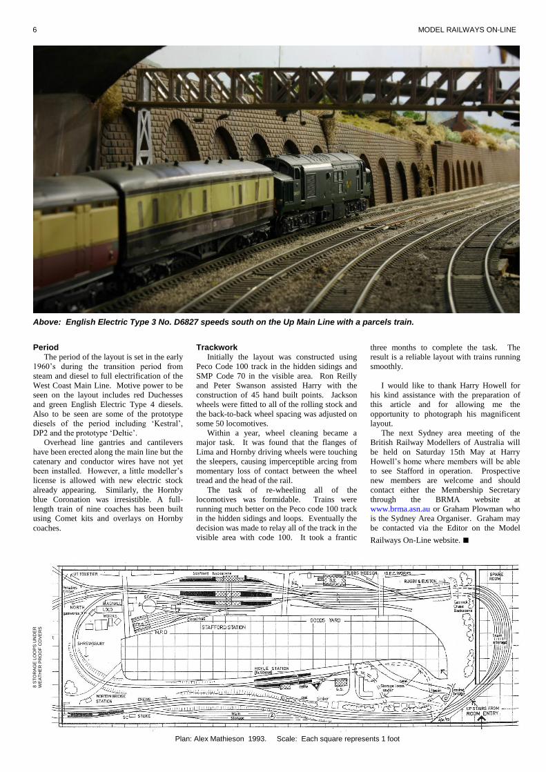
Period The period of the layout is set in the early
1960’s during the transition period from
steam and diesel to full electrification of the
West Coast Main Line. Motive power to be
seen on the layout includes red Duchesses
and green English Electric Type 4 diesels.
Also to be seen are some of the prototype
diesels of the period including ‘Kestral’,
DP2 and the prototype ‘Deltic’.
Overhead line gantries and cantilevers
have been erected along the main line but the
catenary and conductor wires have not yet
been installed. However, a little modeller’s
license is allowed with new electric stock
already appearing. Similarly, the Hornby
blue Coronation was irresistible. A full-
length train of nine coaches has been built
using Comet kits and overlays on Hornby
coaches.
Above: English Electric Type 3 No. D6827 speeds south on the Up Main Line with a parcels train.
three months to complete the task. The
result is a reliable layout with trains running
smoothly.
I would like to thank Harry Howell for
his kind assistance with the preparation of
this article and for allowing me the
opportunity to photograph his magnificent
layout.
The next Sydney area meeting of the
British Railway Modellers of Australia will
be held on Saturday 15th May at Harry
Howell’s home where members will be able
to see Stafford in operation. Prospective
new members are welcome and should
contact either the Membership Secretary
through the BRMA website at
www.brma.asn.au or Graham Plowman who
is the Sydney Area Organiser. Graham may
be contacted via the Editor on the Model
Railways On-Line website. ■
Trackwork Initially the layout was constructed using
Peco Code 100 track in the hidden sidings and
SMP Code 70 in the visible area. Ron Reilly
and Peter Swanson assisted Harry with the
construction of 45 hand built points. Jackson
wheels were fitted to all of the rolling stock and
the back-to-back wheel spacing was adjusted on
some 50 locomotives.
Within a year, wheel cleaning became a
major task. It was found that the flanges of
Lima and Hornby driving wheels were touching
the sleepers, causing imperceptible arcing from
momentary loss of contact between the wheel
tread and the head of the rail.
The task of re-wheeling all of the
locomotives was formidable. Trains were
running much better on the Peco code 100 track
in the hidden sidings and loops. Eventually the
decision was made to relay all of the track in the
visible area with code 100. It took a frantic
__________

MAY 2004 7
Above: Prototype 4000HP Brush/Hawker Siddeley diesel locomotive ‘Kestrel’ heads south with a train of container wagons.
Above: A Sulzer Type 2 passes through Hoyle Station with a short freight train for Shrewsbury.

8 MODEL RAILWAYS ON-LINE
A delightful scene on the Staffordshire and Worcestershire Canal. Fortunately these scenes of a by-gone age have survived and it is still possible to navigate the canals of England. To give added depth, a mirror has been placed under the roving bridge.
‘Lady Godiva’ departs
from Hoyle Station with a
Patriot Class
4-6-0 No.45519
stopping train to Stafford. On
the main line Princess Coronation
Class 4-6-2 no. 46239 ‘City of Chester’
heads north with the Pines Express.

MAY 2004 9
Westerham First in a series of prototype layouts
by Paul Plowman
History The branch line between Dunton Green on the South Eastern and
Chatham Railway main line and the market town of Westerham opened
in 1881. The line was single track throughout and just under five miles
in length. There was an intermediate station at Brasted, which had a
small goods yard and a halt at Chevening. There were no passing
places on the line. It was intended to extend the line to Oxted but in
the event the proposed level crossing across London Road was never
built.
Memories of the line My first acquaintance with the line was about 1954 on a cub scout
outing. The pack travelled from Grove Park to Dunton Green by
electric train. We crossed over to the branch platform where an
H Class 0-4-4T was waiting with a two-coach, former L.B.&.S.C.R.
push-pull set. The set was painted in crimson and I can remember a
second set being stabled in the run round loop in freshly painted green.
The train ran with the loco leading along the branch. From Westerham
Station we had to walk all the way up to Hosey Common where our
campsite for the day was located. Then in the evening we had to walk
all the way back again. As we arrived at Westerham Station the train
was waiting but this time the loco was at the Dunton Green end of the
train. Again it was a former L.B.&.S.C.R. push-pull set in crimson and
I can remember it being quite tatty. While we were waiting for the
connection at Dunton Green the ‘Arrow’ came racing through on its
way to Victoria. Regrettably that was the only trip I had along the
branch.
In the late 1950’s we used to go fishing at Tonbridge. The main
line was only electrified as far as Sevenoaks where one had to change
to steam. After the morning service the Westerham Branch train
worked empty stock to Sevenoaks and then formed a stopping service
to Tonbridge. Oh, the joy of travelling through Sevenoaks Tunnel with
dim lights and smoke swirling in through the windows! Those were
the days! On one occasion the journey home was behind a Q1 0-6-0.
The layout looking westwards on 1st September 1962. In the foreground can be seen the remains of the engine shed. The inspection pit had been filled in but was later dug out by volunteers. Photo: Paul Plowman
Above: Westerham Station viewed from the buffer stops. The date is believed to be about 1928. The engine shed is just visible in the far distance. Photo: Source unknown

10 MODEL RAILWAYS ON-LINE
Westerham Station viewed from the roof of the water tower on 1st
September 1962. The white building on the right of
the picture is the Crown Hotel. Photo: Paul Plowman
Association was formed to fight the closure and leased the station
during 1962 and 1963 but it was all doomed to failure. Unfortunately
the Association comprised two factions. The local group who had
formed the Association were primarily regular passengers interested in
persuading BR to restore the service. Then there was a large wider
membership of enthusiasts who saw it as a chance to create another
Bluebell Railway (The Churchill Line). By the time the steam
enthusiasts and preservationists gained control of the Association it
was too late. Kent County Council wasted no time filling in the cutting
at Chevening for the Sevenoaks By-Pass. The section of line between
Chevening and Brasted is now under the M25 Motorway.
The membership had raised sufficient money to purchase an
H Class 0-4-4 tank engine and this loco can now be seen on the
Bluebell Railway. Two members purchased coaches for use on the line
and these can now be seen at several locations around the country.
The Layout Westerham was a simple terminus with a single platform 290 feet in
length, just long enough for five coaches. The run-round was about
480 feet, long enough to clear eight coaches. However, if the loco was
to shunt into the yard it was possible to run round an 800 foot train.
The station had all the usual features we find in a small terminus; a
small goods shed, an end loading dock, a yard crane, a signal box, a
water tower, and an engine shed.
A model could be built in 4mm scale on two feet wide baseboards.
_______________
My grandparents retired to Polegate near Eastbourne and once a
month during the late 1950’s my brother and I had to endure a trip by
car from South London. The route took us via Westerham and over the
Ashdown Forest. Occasionally we saw a train as we passed Hartfield
Station on the Tunbridge Wells West to East Grinstead line. On the
return journey we would stop at Westerham to use the facilities
provided by the Crown Hotel. The Hotel is just across the road from
the station. I can remember seeing the train waiting there on dark
nights and being able to look right through the booking hall to see the
dimly lit carriages. Looking at the plan accompanying this article, the
doors of the booking hall are not in line with each other but when
viewed from the toilets outside the Crown Hotel there is a sight line
right through the building!
Closure The line eventually closed on 30th October 1961. At the time there
were 200 passengers a day using the line. The Westerham Railway
________
Westerham Signal Box on 10th November 1963. The Association had repainted the structure and replaced the broken windows. Photo: Paul Plowman
The station building on 16th November 1963 seen partly repainted by the Association. It was finally demolished in 1966. Photo: Paul Plowman
If space was available for three feet wide boards this would provide
room to model the coal merchants area and a low relief frontage to the
Crown Hotel. The overall length from the home signal to the buffer
stops would be 16ft 6in without compression. The three turnouts in the
passenger carrying line were all C9’s with straight switch planing and
the turnout by the loco shed was a B8. The crossover in the yard
appears to have been made up from a B7½ to a B6. By using Peco
large radius points, which approximate to an A6½ turnout the length of
the model could be compressed. by about 18 inches. By shortening the
platform to four coaches, reducing the shunt neck and moving the
home signal closer a further two feet could be saved, bringing the over
all length of the model down to 13 feet.
At the time of closure the track on the branch was still exclusively
bullhead.
References ‘The Westerham Valley Railway’ by D Gould. Published by
Oakwood Press, ISBN 0853615152
Branch Line Video ‘Classic Southern Region’ Volume 1
Westerham, Hawkhurst & Allhallows on Sea. ■

MAY 2004 11
This page will be used for the plan of Westerham

12 MODEL RAILWAYS ON-LINE
ASHPRINGTON ROAD – Part 2
A 00 layout based on the Western Region Main Line between Exeter and Plymouth
By Graham Plowman
Time has been passing and it is now 1984 on the South Devon Railway
A paper template of the layout
The next step was to build a paper
‘model’ of the layout. For this I used sheets
of newspaper held together with sticky tape
and cut them to the shapes of the boards.
These were laid out on the floor of the
railway room to give a full-size
representation of the layout. This is also a
good technique for refining the board shapes.
I had worked out the board shapes
mathematically, but it wasn't until I created
the newspaper templates that I found that
one of my calculations was incorrect and
needed revising. This could have been a
costly error if I had been constructing with
timber!
With the newspaper templates on the
floor, I laid track loosely on them to get an
idea of how the layout would appear.
Fortunately, the track fitted on the ‘boards’
without any problems. The paper templates
were also used to determine the position of
____________
Above: An HST bound for Penzance passes Class 50 No.50043 ‘Eagle’ with a train for Bristol. The Exeter Area Resignalling Scheme is under way and the semaphore signals at Ashprington Road will soon be replaced by colour lights.
board bracing to avoid conflict with point
motors. Building the baseboards The baseboards were built using 12mm
plywood because this material stands up to
changes in temperature and humidity much
better than the traditional chipboard and 2-by-1
method. I had also obtained a large amount of
Dexion (the giant Meccano used for shelving
racks) to form the bracing beneath the boards.
With 12 boards to build, construction took a
couple of months. The boards are held together
with bolts and each joint is supported by a pair
_________________
of legs. When all of the boards were
completed and erected, they needed to be
levelled. I used a builder’s spirit level and
found that I needed to make a number of
adjustments to ensure that all of the boards
and particularly the joints, were level.
After levelling, the track layout was
drawn out on the surface of the boards.
Large curves were marked out using a
measuring tape. I positioned my folding
workbench in the middle of the layout and
held a piece of timber in a vice with a nail in
the top. A tape measure was hooked on to
the nail and the arc marked out on the
boards. This was done for curves at both
ends of the layout but proved more difficult
on the ‘London’ end because the board level
is 20icm lower for the viaduct. Years ago,
my father was lucky enough to obtain some
railway drawing curves, which were being
disposed of by a drawing office. These have
been invaluable.

MAY 2004 13
Viaduct Construction I have always felt that having model trains
going over a bridge or viaduct adds an extra
dimension to the appearance of a layout.
Before commencing construction, I
undertook some research examining pictures
of viaducts in Devon and Cornwall. The
purpose of this was to identify the little
details and techniques used in building the
prototype that are so often missed in models:
There is rarely much distance between
the top of the arches and the underside of
the track. From the underside of the
sleepers to the top of the brickwork can
be as little as six inches of ballast!
The locating holes used to position the
timber formwork used during
construction are often missed.
The stonework ‘style’ often changes
between the pillars and the viaduct
arches.
Many viaducts have refuges for track
staff to stand in safety when a train
passes.
Some viaducts have fencing instead of
parapet walls.
Those with fencing have low parapet
walls usually only just high enough to
retain the track ballast from falling off.
Most viaducts (in the UK) have some
form of guardrail device to restrain a
derailed train (see my article on Guard
Rails in the first edition. Ed.).
I chose to base my model on Clinnick
Viaduct, which is a six-arch structure on the
6imile bank between Doublebois and
Bodmin Road in Cornwall. The structure is
straight, so some modeller’s license has been
applied by building the model to suit a curve
on my layout.
Clinnick Viaduct is a very good example
of the standard design of viaduct used in the
Devon and Cornwall area, representing a
tidy, yet interesting structure. Building the
model turned out to be a mammoth task.
The basic structure was constructed using
plywood, nailed and glued together. It is a
complete self-contained unit, which can be
removed from the layout. It has a ‘novelty’
feature in that because there would be a
point motor located between two of the
arches, there is a cable ‘pull string’ that can
be used to pull cables up and down the inside
of the pillar. The structure was covered with
Polyfiller. This was left for two days to dry
before starting the carving of the stonework.
I used a modelling drill with a mini
‘countersink’ and this worked very well.
However, the carving process took an
inordinate amount of time to complete to the
point where I almost lost interest! The moral
here is to build a smaller viaduct! Capping
stones were made of balsa wood. These
were attached first and then rubbed down to
shape. Side fencing, made by Faller has been
purchased but not yet fitted.
Preparing the trackbed I decided from the outset that all of the
main running tracks would be canted (tilted)
on curves. To achieve this requires a
_______________________
different approach to construction from the
conventional method of laying track directly
onto the board surface. I used a layer of 6imm
plywood to form a sub-base for the trackbed.
At the outer edge of the sub-base, on curves, a
1icm wide strip of 3imm thick hardboard was
tucked under the edge to provide a tilt. The
assembly was held in place by screwing to the
main baseboard.
Where curves pass through a transition into a
straight, the construction becomes more
complicated requiring the hardboard to be
progressively increased, or reduced in thickness.
Suffice to say that prototype geometry has been
adopted. This was achieved by using
professional railway alignment design computer
systems and plotting the plans to 1:76.2 scale
for laying directly onto my baseboards.
Because we have to make significant
compromises for the radius of curves on our
________________
model layouts, all of the transitions on my
layout correspond to the minimum length
permissible on the prototype. This scales to
about 26cm long, or about the length of a
coach. The 3mm packing under the trackbed
described above, creates an angle of super
elevation, which is equivalent to 2 inches of
cant on the prototype.
I have chosen to have both tracks canted
in the same plane as this significantly
simplifies construction, and enables
crossovers to be located on curves. There
are several other possible configurations for
canting pairs of tracks. The emerging
standard appears to be for the two inside
(sixfoot rails) to be at the same level and for
the outer (cess) rail of the outer track to be
raised through transitions while the inside
(cess) rail of the inner track is lowered
through transitions.
A London bound HST emerges from the tunnel to the west of Ashprington Road
A set of points and a pair of working ground signals are positioned on the viaduct. The cables to the point motor and the pull rods for the signals pass down through the pier of the viaduct

14 MODEL RAILWAYS ON-LINE
The electrical system Once a trackbed has been prepared, there
is a great temptation to start laying track.
However, this can lead to all sorts of
problems such as the track having to be
pulled up to fit insulating joints or the use of
rotary saws to cut rails to create isolating
gaps. It becomes necessary for wires to be
soldered to the sides of rails, resulting in
unsightly solder globules and melted plastic
sleepers, which destroy any possibility of
realism. Planning beforehand prevents all of
these problems.
I designed the electrics in the form of a
feed diagram. This included all isolating
sections, overrun dead-sections, signal
run-past sections and switching between
controllers. Using this diagram, I would cut
the rails appropriately and fit isolating
fishplates where required.
Although supplied as ‘live frog’ turnouts
which can be connected up and used ‘as is’,
the Peco codei75 turnouts are designed so
that they can be re-wired to meet the
modellers’ requirements. Essentially, the
switch rails can be connected electrically to
the stock rails and isolated from the crossing
vee. This enables the vee to be fed
_____________
separately and not to rely on the contact of the
switch rails. To prevent any possibility of
shorting on the backs of the switches caused by
out of gauge wheels, I have rewired all of the
turnouts to provide separately switched feeds to
the crossing vees. Point motors are mostly Peco
and use the Peco switches. In certain situations,
Seep motors were later used as these proved to
have much more reliable switches.
Signals are GW lower quadrant semaphore,
using mechanical relays. Since the layout is
also required to represent the BR blue period,
the use of semaphore signals dates it to 1984 at
the latest. After this date Exeter Control Centre
came into use and all signalling in the area was
replaced with colour lights.
Track laying Track laying commenced once the electrical
diagram had been completed. Track was glued
down using either Evo-stik or PVA after the
appropriate wires had been soldered to the
undersides of the rails.
Computer control system As previously mentioned, the layout is
computer controlled. The system controls all
movements of points and signals but it
________________
does not drive the trains. Trains are driven
using conventional Gaugemaster WS
handheld controllers.
I have used the ‘Remote Panel Control’
hardware system available from the Model
Electronics Railway Group (MERG). The
core of this system is a control board, which
connects via a cable to the RS232 port of a
PC computer. A number of other boards
connect to the control board to form a stack.
There are boards containing 8 relays, 32
logic level outputs, 32 logic level inputs and
8 track circuits.
The relays are used to control track
section switching between controllers and
switching of isolating sections. The logic
level outputs are used for controlling the
point motor modules and signals. The signals
are mechanically powered from relays
connected to the logic level outputs.
Using this system, there is no need for a
control panel – on this layout it is a computer
screen.
Computer software The software used is the ‘Solid State
Interlocker’ (SSI) software from
GPP Software.
HST’s pass at Ashprington Road Station

MAY 2004 15
The website address is
www.gppsoftware.com/ssi/ssi.asp. This is
the only software available, which represents
British practice. SSI simulates modern IECC
computer control systems used in UK
signalling centres and looks and operates
like the real thing, including graphics and the
mouse operation of Entry/Exit route setting.
The SSI software supports a fully
signalled and interlocked layout and these
capabilities have been fully utilised..
Signalling Signals are constructed from Ratio kits
suitably modified. They are all fully working
including ground signals and are operated
from the mechanical action of relays
controlled by the computer system.
Scenery
Once the signalling was completed, a
start was made on the construction of the
scenery. Wood-fibre insulation board was
used for the formers, which was cut to suit
the profiles of embankments and cuttings.
The gradient of cutting and embankment
slopes is 1 in 1½. This is about the
maximum value for normal soils. Rock can
be steeper and clay is shallower. I made up
a 1 in 1½ triangle from card as a template for
slopes.
The scenery formers were covered with
chicken wire. Layers of newspaper soaked
in plaster have been laid over this to create a
reasonably thick surface with some strength.
When dry, this was all painted in a light
green, which can be seen in the photographs.
This is a base colour for the scenery and will
later be covered with scenic materials.
Buildings ‘Ashprington Road East Signal Box’ is a
Ratio ‘Highley’ kit and the west signal box
is from Hornby. The Hornby model is of
Hagley Signal Box and their GWR
footbridge kit is from the same location. I
will be installing the footbridge at a later
date but temporarily I am using an
Airfix/Dapol kit footbridge.
Other buildings to be constructed will
include a stationmaster’s house, which will
be made from Linka. A goods shed and the
abutments for the bridge over the railway at
the western end of the station will be
constructed using the same techniques as I
have described for the viaduct. The steel
plate girders of the bridge are MDF and will
be detailed with plastic and metal strips. The
tunnel mouths are from Merit.
Rolling Stock My collection of rolling stock falls into
two distinct periods, late BR steam with
early diesels and the blue period of 1984.
Steam locos are a mixture of Bachmann,
Hornby and Mainline with early diesels from
Bachmann, Mainline, Lima and Heljan. All
have been weathered. The 9F and the
Britannia are hand built. The construction of
the Britannia is featured on page 16 of this
edition of the magazine.
Diesel locos in the blue period are
____________
Above: A Class 31 A1A-A1A emerges from the West Tunnel and enters the Up Yard with a freight composed mostly of lwb open wagons.
Above: Class 50 No.50043 ‘Eagle’ coasts over the viaduct as it approaches the station with a train for Plymouth.
from Mainline and Lima.
Coaching stock for the steam era is
predominantly Bachmann MK1’s with a few
Replica and Hornby coaches, while for the later
period they are mostly Hornby and Lima.
Wagons are a mixture of Bachmann,
Replica, Hornby and Dapol.
Operation The computer control software provides for
_______________
timetables and schedules. I am currently in
the process of testing a schedule prior to
entering it into the software.
Summary I would like to thank my wife for all of
her support and for her tolerance of my
hobby. Thanks also to my father for his
professional expertise and assistance in
designing the track layout. ■

16 MODEL RAILWAYS ON-LINE Having successfully completed building a
BR 9F locomotive, I decided that I wanted to
model a Britannia 4-6-2 Pacific as my next
project.
Research I purchased the Ian Allan book ‘BR
Standard Pacifics In Colour’ (ISBN 0-7110-
2264-x). This is one of a series of several
dozen books published by Ian Allan, all of
which contain 100% colour pictures of BR
Steam from the 1950’s through to the
1960’s. These are all excellent books and
invaluable material for the modeller of the
early BR period.
The Britannias were the first of the BR
Standard designs, being built between 1952
and 1954. Their design was the
responsibility of Robin Riddles CBE and his
team who included Roland Bond and
Stewart Cox. Many texts have been written
as to the reasoning behind the building of the
BR Standards, so I will not cover this here,
suffice to say that there was a need for a
class 7P express passenger locomotive.
The first of the new locomotives was
named ‘Britannia’ by the then Minister of
Transport, Alfred Barnes at Marylebone
Station on 30th January 1951. When Robin
Riddles renamed ‘Britannia’ after its original
restoration on the Severn Valley Railway in
May 1978, he revealed the reason for the
name as coming from the coat of arms of the
London and North Western Railway, which
had Britannia included within it. He also
started his career with the LNWR. He
believed that the name would be fitting for
both his first locomotive and for his new
(and last) employers.
Technical details Class 7P Britannia 4-6-2
Built: 1952-54, 55 built
Weight: loco 94 tons
Wheels: 3’0”, 6’2”, 3’31/2”
Boiler Pressure: 250 lb/sq. in
Tender 49.15 tons
Tractive effort: 32160 lbf
Cylinders: 2 (20” x 28”)
Valve Gear: Walshaert
Route Availability: 7
Building a Britannia Class 7P 4-6-2
By Graham Plowman
Graham describes how he built a model of Morning Star
Two of the class, No.70000 ‘Britannia’ and
No.70013 ‘Oliver Cromwell’ are preserved.
No.70000 has been fitted with dual air and
vacuum brakes fitted while in preservation.
The Britannias were allocated to the various
regions as follows: Locos 70000 to 70014 were
allocated to Stratford except 70004 (William
Shakespeare) and 70014 (Iron Duke) which
were seconded to the Southern Region for use
on the ‘Golden Arrow’ service. These were
named after historical characters. The second
batch, 70015 to 70029 were allocated to the
Western Region. These were named after GWR
broad gauge engines. 70030 to 70034 went to
the Midland Region and were named after poets
and writers. 70035 to 70043 were named after
writers and historical figures and went to the
Great Eastern. 70043 and 70044 were allocated
to the Eastern Region but went on loan to the
Midland when new, together with the rest of the
class up to 70049. This batch bore the names of
military gentlemen with the exceptions of 70046
‘Anzac’, 70047 the only Britannia which was
never named and 70048 ‘The Territorial Army
1908-1958’. 70048 had the only name in the
class which ran to two lines on the nameplate.
70049 to 70054 were named after Scottish
waterways, these all being allocated to the
Scottish Region.
Like many new designs, the Britannias
suffered a number of teething problems,
including breakage of cast iron piston heads.
The cause was identified in the dome where the
level of steam intake was only 11¾ inches
above boiler water level. This necessitated the
fitting of a higher dome to prevent excess water
overflowing from the boiler being carried down
into the cylinders. A number of coupling rod
and pin problems occurred in addition to a
tender parting from its loco!
Perhaps the most well known problem with
Britannias was on the Western Region, which
led to changing the design of smoke deflectors
fitted to most of the class. No.70026 ‘Polar
Star’ derailed at Milton between Steventon and
Didcot with the loss of 11 lives and 157 injuries.
Permanent way relaying had necessitated slow
line running but the driver failed to negotiate a
crossover at the required 10mph and did so at
50mph, taking the entire train off the rails.
_________
The subsequent enquiry blamed a
combination of left-hand drive, bad weather,
poor visibility, a fireman unused to the road
and the handrails on the smoke deflectors as
the cause. The enquiry recommended
changes to the smoke deflectors. The
Western Region over reacted, removing the
original handrails and covering the smoke
deflectors in hand holes, whereas the
Midland Region made a much tidier
two-hole modification.
Britannias were paired with a number of
tenders. The first 24 locos of the class and
70039 to 70044 had BR1 tenders, 70025 to
70029 had BR1A tenders and 70045 to
70054 had BR1D tenders.
The first Britannia withdrawn was
No.70007 ‘Coeur de Lion’ in June 1965. The
last was 70013 ‘Oliver Cromwell’ on
12th August 1968.
Planning the project I model the early 1960’s period on the
Western Region and chose to construct a
Britannia allocated to that region. This
determined the tender paired with the model
and also the smoke deflectors. I think the
Western Region spoilt the appearance of the
Britannia smoke deflectors, so I chose to
model the ‘odd one out’, No.70021
‘Morning Star’, which did not have these
modifications. I have a picture of ‘Morning
Star’ taken in September 1967 shortly before
withdrawal and it still had the original smoke
deflectors most likely because it moved to
the Midland Region before it was modified.
Other than this, my model would be a
standard Britannia with all the normal
fittings and nothing out of the ordinary.
The following components were used in
the construction of the locomotive:
Hornby Britannia body. I had an
unpainted body from the factory without
fittings.
Crownline detailing, smoke deflectors,
handrails, sprung buffers, all fittings,
pipework. Etc.
Comet Brass chassis kit.
Gibsons RP25 wheels.
Portescap motor.
Airfix kit 9F tender, to be extensively
modified.
Romford Screw link couplings.
CGW nameplate and smoke box
numberplate for No.70021, ‘Morning
Star’.
DJH Britannia trailing pony truck. Comet
recommend the Hornby version, but it
lacks so much detail when compared with
the DJH version.
Genuine coal for tender.
PC Models transfers and lining.
The model after fitting the Crownline components

MAY 2004 17
Preparation A number of construction issues needed
to be resolved before I started building.
Electrical pickup would be via Gibson’s
plunger pickups on all driving wheels.
Tender pickup would also be provided using
conventional ‘wiper’ strips. The motor
location was chosen in the firebox and it
would drive the axle of the rear driving
wheels. Attachment of the body to the
frames would use the slot in the Hornby
back head and the screw hole under the
smoke box. Chassis frame spacers would be
suitably positioned, taking into account the
location of the plunger pickups.
Construction Work commenced on the locomotive
chassis. The Comet chassis needs to be
soldered together and when complete, it
provides a nice firm frame. I find the Comet
chassis to be very accurately made and they
fit together squarely very easily – well done
Comet!
I decided not to compensate the chassis.
I have mixed feelings about compensation.
On the one hand I feel that if you need
compensation in OO then your track can't be
laid very well and it can cause clearance
problems with coupling rods behind cross
heads. On the other hand, not everyone
builds 100% level track so my model could
potentially be prone to derailing. I later
found no problem at all.
It was important to make sure that all
wheels touched the rails and the whole
assembly was dead square.
Fitting the body to the chassis was quite
straightforward as the Comet chassis is
purposely made for the Hornby body. I
should note at this point that over the years,
Hornby have modified the Britannia body
since its original Tri-ang days. Earlier
versions have a higher buffer beam relative
to the boiler-side running plate and I believe
they were also a different length. The Comet
chassis will only fit the later body style, i.e.
the current version, which appears to be
accurate in basic dimensions.
The only problem I found is that there is
no provision on either the Hornby body or
the Comet chassis for a tender coupling.
_____________
I therefore improvised with an Airfix kit 9F
coupling. The boiler was filled with lead
weighting.
Bodywork The Hornby body requires relatively little
preparation for use when purchased in its
unfitted and unpainted form. I used all of the
Crownline detailing pack components and
fittings, in some places replacing Comet
components, as the Crownline components were
more detailed.
One nice feature is that the Crownline pack
comes with some large chunks of metal, which
fit behind the firebox sides and under the
footplate. Their purpose is to give the firebox
some ‘body’. This really does bring the
character out over the Hornby model. It makes
the firebox look as though it is solid right
through, giving a chunky impression and
making it look very realistic.
Previously on my 9F I had chosen not to use
the Crownline firebox-top pipe work but
______________
on this model I decided that I would use it
even though it is slightly over scale.
Looking at pictures of Britannias, I noticed
that the mass of pipe work all over the
firebox is very prominent and it looks
extremely untidy. I decided that this ‘image’
could be achieved with slightly over scale
Crownline components and proceeded to use
this method with very realistic results. I also
used some copper wire in places where
Crownline omit components.
The chimney and dome were replaced
with brass and white metal components
respectively. I used many other Crownline
parts to detail the body such as handrails,
knobs, smoke deflectors, boiler top feeds,
smoke box door fittings, steps, buffers and
brake pipes, etc..
The pipe work on the side of the firebox
is such that it restricts the movement of the
pony truck. I fitted the pipe work so that the
locomotive would negotiate the tighter 2’-6”
radius of a Peco large radius curved turnout.
To make the loco negotiate anything sharper
would have meant omitting the pipe work
altogether and resulted in a model lacking in
detail!
Fortunately I have no curves on my
Ashprington Road layout, which are sharper
than the 2’-6” radius mentioned.
Valve Gear This is supplied by Comet as a nickel
silver sheet with dozens of parts. I cut out
the required parts and soldered most of them
together. When using Gibson’s wheels, one
has to be careful with the heat from a
soldering iron near the plastic spokes.
Gibson’s wheels are designed for their own
system of crankpins which I also used. I
find these components easy to work with and
they look better than Romford equivalents.
I can’t get on with laminated coupling
rods. I find them incredibly difficult to
_________
The chassis with Portescap motor fitted
Close up of the cab and pipe-work detail

18 MODEL RAILWAYS ON-LINE
solder together. I would prefer solid/ cast
nickel silver components instead.
Fortunately, only the coupling rods were
laminated on this model. The Britannias
were built with fluted coupling and
connecting rods but in later years, many had
their coupling rods replaced with flat non-
fluted rods.
The Tender This required the most work. The
Britannia has a BR1 tender, which is very
similar in appearance to the BR1G used by
the 9F’s, so I chose to use a tender from an
Airfix 9F kit. I have since found that Comet
make a suitable tender kit in brass and white
metal!
I prepared all the parts, cut off handrails,
replacing them with brass handrails and cut
off the plastic ladder on the back. I later
soldered up a ladder from copper wire as a
replacement.
The tender was weighted with two lead
sheets along the insides. Gibson’s wheels
were fitted on Lima axles, running in Peco
bearings. I had previously used this
combination on my 9F but unfortunately it
did not work very well on this model.
______
Lining was achieved using PC Models
press-fix lining. I find this easy to work with
and it gives very fine results. After fixing, I
immediately varnished the loco and tender
body to prevent the transfers coming off. I
hand painted the lining on the sides of the
footplate. Transfers would not have stuck to
this. I am fortunate to have reasonably
steady hands, so the lining came out quite
well. Hornby also hand paint this part of
their models.
Weathering Next came the task I enjoy most,
weathering. I think the Carrs modelling
powders are excellent for this and provide an
easy way to achieve a very realistic finish. I
would always recommend obtaining colour
photographs of the subject before attempting
any weathering. If you make a mistake with
Carrs powders, a damp sponge easily takes
you back to the start. I apply the powders
using an old toothbrush and find that I don't
need to 'fix' them afterwards. However, an
artist’s matt spray varnish can be used if
required.
I decided that my Britannia would only
have a light dusting, giving a finish that
looks as though the loco has been in service
but has been relatively well looked after.
For this purpose, I used a combination of a
few brown coloured powders in extreme
moderation. Colour photos provided
excellent examples for matching of colours.
The principal effect required was to obtain
an ‘ash’ appearance all around the underside
of the firebox and a general ‘ash and brake
dust’ appearance on the chassis.
Running in Having built the locomotive, it needed to
be lubricated and run in. Unfortunately, I
had a few teething problems with the driving
wheel quartering and ‘wheel wobble’, which
required the wheels and coupling mechanism
to be dismantled several times. Once fixed,
the Portescap motor manages to power this
model very smoothly. I became somewhat
disappointed with my Bachmann ‘Mere
Hall’ when it did not match up to the smooth
running of the Britannia! ■
I could not get the wheels to run true on the
axles. I think they probably came from a faulty
batch. I obtained replacements, which ran
better. They are still not perfect and I am not
entirely happy with the tender chassis. It doesn’t
sit totally square on the rails in certain situations
and the wheels still wobble slightly, although
not noticeable to the untrained eye. At some
point in the future I am planning to replace the
tender chassis with the Comet kit, which has
inside bearings.
The tender was filled with coal, which was
fixed using the standard method of watered
down PVA with a drop of washing up liquid to
break the surface tension.
Painting I painted the whole locomotive in BR
Standard Loco Green using Railmatch paint.
This gives a nice finish. Later I added some
Carrs Modelling powders for weathering. I
used Woodhead transfers for the numbers and
coat of arms on the tender - the Britannias had
the same left-facing lion on both sides.
Humbrol Matt Black was used extensively.
Pipe work and coupling rods were painted using
a mixture of Humbrol Scenic Track colour, with
Railmatch ‘oily steal’ and ‘frame dirt’.
The finished model
Hints ‘n Tips: Repairing Heljan Hymek Buffers by Graham Plowman
Unfortunately my Heljan Hymek arrived
with a broken buffer.
Repair was not a case of simply gluing
the broken part back on because it was
missing from the box. Firstly a small
amount of Super Glue was placed on the
broken edge of the buffer. It was then built
up with Humbrol Model Filler, which mixed
with the Super Glue to obtain a solid
attachment. Humbrol Model Filler is a paste
with a consistency rather like toothpaste and
is very hard when set. It is intended for
filling cracks and holes in models. When the
filler is set, a file can be used to shape the
buffer and after painting, the model looks as
good as new. ■

MAY 2004 19
Westerham Station in 1962 shortly after closure viewed from the loading dock. The shed beside the station building is labelled on the plan as a ‘Cycle Shed’. However, the author recollects it being used as a lamp room. The building beside the goods shed is shown as a ‘Cement Store’ but had been disused for a number of years. Photo: Terry Tracey
H Class 0-4-4T No.263, which was purchased for use on the Westerham Branch eventually found a home on the Bluebell Railway in Sussex. It is seen here in full S.E.&.C.R. livery at Horsted Keynes on 9th May 1982. Photo: Paul Plowman

20 MODEL RAILWAYS ON-LINE
The Model On opening the box, the first thing that is
noticeable is the amount of detail on the
model. Removal from the usual polystyrene
tray is straightforward. The only extra part
in the box is a small packet containing
detailing pipe work for the rear buffer beam.
Moulding and painting is very crisp all
over and the model has certainly captures the
overall image of the prototype very well,
including rivets. The cab is fully detailed
including back head and driving controls.
This is possible because the motor is
mounted in the firebox. The buffers are
sprung and are of a consistent height above
rail level at both ends of the locomotive.
Couplings are fitted into NEM pockets,
which are attached to the pony trucks. The
axles on the pony trucks are completely
unrestrained in sideways movement and can
actually slide 3mm, although when running
they appear to centralise themselves.
Coupling tension causes centring although
propelling might cause the axles not to be at
right angles with the rails. The author
suspects that the pony trucks have been
designed this way to afford increased
sideways movement of the coupling on
curves but feels that it is quite unnecessary.
Even on moderate curves it is noticeable that
the guard irons are not always in line with
the wheels and rails. The irons are set at
16.5mm gauge. This movement is far too
much and could be remedied by the fitting of
washers.
The sample under review unfortunately,
suffered from a number of quality control
problems, which could easily be remedied by
most modellers. The model is supplied with
brake rigging already attached but on this
model it was not fitted correctly and was
____________________________________
__________
Bachmann’s latest release comes in the
form of an ex GWR 45xx Class 2-6-2 prairie
tank, a very notable omission from the
Western market space, especially since the
demise of the similar Lima version.
Prototype History The 45xx was a development of the
earlier Churchward 44xx Class 2-6-2T
locomotives. It was almost identical to the
44xx, the only major difference being the
larger 4’-7½” driving wheels and the drop
end curved arrangement of the running plate
profile from No. 4534 onwards. The
increased driving wheel size made the 45xx
a generally more useful loco because of the
possible increase in speed. The 45xx was
widely used on branch lines, both
______________
Review of the Churchward 45xx from Bachmann
By Graham Plowman
for passenger services and for goods trains.
Built originally at Stafford Road Works,
Wolverhampton between 1906 and 1908, the
first batch of 45xx locomotives were
numbered 2161-2180 and later renumbered
4500-4519. The second batch, Nos. 2181-
2190 was constructed at Swindon from 1909.
Renumbering to 4500-4574 took place in
1912.
Five batches of 45xx were built at
Swindon until construction ceased in 1924.
They were superseded by the 4575 Class
three years later. Withdrawals commenced
in 1950, primarily due to the age of some of
the earlier examples. Fortunately, we can
still see the 45xx as Nos. 4555, 4561, 4566
and 4588 have been preserved.

MAY 2004 21
hanging loose. The lamp irons above the
front buffer beam are not straight. Probably
the most noticeable problem is the number
plates on the coal bunker sides, which are
printed (even though the prototypes were
castings) and they are not horizontal. They
lean downwards towards the back of the
locomotive. The careful observer will note
that even allowing for perspective, it is
possible to see this problem in the
photographs published in the Bachmann
2004 catalogue. The slide bars have not
been fitted correctly. On one side, they lift
up towards the cab and on the other they
drop down towards the track. They should be
level. The crosshead and vacuum pump
casting looks a bit crude. Coupling rods are
realistically darkened and the overall finish
of the model is very well done. There are no
mould joins along the top of the boiler.
Instead, they are very fine and cleverly
aligned with the handrails along the side of
the smoke box so as not to be noticeable.
From No. 4520 to 4554 the class was built
with copper capped chimneys and from
No. 4555 onwards they were built with cast
iron chimneys without a copper cap. All of
the 4575 Class had cast iron chimneys. The
model of No. 4560 correctly portrays a cast
iron chimney with no copper capping. A
minor point, but the whistles are too far
forward from the cab by about 2mm
according to scale drawings.
This model is NOT designed for the
fitting of screw couplings. The body
retaining screws are located directly behind
the buffer beam, in exactly the location
where the shank of a hook would pass
through and where the coupling spring
would be located. It is concerning that the
author recently reviewed a new model from
another manufacturer, which was also
designed not to permit the fitting of screw
couplings. There seems to be an incorrect
assumption that the provision of NEM
pockets means that nobody will want to use
other coupling systems! The footplate and
buffer beams are metal.
Performance Straight out of the box, this loco ran
extremely smoothly in both directions.
Electrical pickup is via wipers on the backs
of the driving wheels only. This is contrary
to a review in one of the mainstream
magazines. The author believes that the
reviewer mistook the copper/bronze pony
truck springs as pickups. There were
certainly no pickups on the pony trucks of
the model in this review and there were no
problems with electrical pickup.
After a short period of running it could be
seen that the model had a distinctive ‘limp’
when running in the reverse direction. This
wobble needed close observation to be seen.
Further inspection revealed that the rear
driving wheel on the driver’s side was not
concentric on its axle and it could be seen
that the flange varied in depth as the wheel
revolved. A check of the wheel tread
removed some excess black paint, but this
did not resolve the problem. Closer
inspection of the wheel treads leads the
________________________
author to believe that the tyres on this loco may
be cast and not machine turned as on other Blue
Ribband models. This was evidenced by the
treads on one side having pitted surfaces,
blemishes and a couple of nodules reminiscent
of the early cast wheels, which Bachmann used
to fit. Or possibly the material used was not of
a quality standard.
All wheels have the correct number of
spokes. Drivers are 18.48mm in diameter. The
prototype drivers were 4’-7½”, which equates to
18.49mm – so are spot on. Pony wheels are
12.6mm, equating exactly to the prototype
3’-2”. Back to back wheel measurement is
14.3mm.
The haulage capability is extremely good
due to the weight of the model. It is very easy
to take apart by removing two screws located
behind the buffer beams at each end. The
chassis is very neat and tidy with a centrally
mounted motor driving the centre axle through a
worm and gear train. Of particular note is that
when assembled, it is not possible to see the
mechanism, because it is effectively sealed in
due to the weights located in the side tanks
aligning with the chassis block. This is a very
good idea and keeps dust and dirt out of the
mechanism.
Once dismantled, the obvious omission
inside is a ‘plug and play’ DCC socket. This
____________________
model has a small PCB, which requires
two coils to be removed and wires to be
soldered to fit a decoder. When one
considers that Bachmann has now entered
the DCC market in the UK with its own
system and has been pushing the merits
of DCC for some time, it is really
surprising that this latest addition to their
range doesn’t have a DCC socket
facility, especially when there is ample
room inside for such a fitting.
Verdict Although the model under review had
a number of minor quality control
problems, most of them could be fixed by
the average modeller. The appearance of
the model is excellent. It is very well
finished and accurate in all the major
dimensions and certainly portrays the
image of the prototype in every way.
It is a very useful addition to any
GWR or BR(W) layout as these
locomotives were widespread in their
operation, especially on branch lines.
As with any model purchased these
days, the advice is to ask your dealer to
test run the model for you before buying.
■
22 MODEL RAILWAYS ON-LINE
Those Squares! Had a look at the magazine and I think
it is really good. The only problem I have
is that it has lots of little squares all over
every page. Whether its conversion to
PDF has caused this I don't know. Has
anyone else reported any problems in this
respect?
I like Graham's article on the Heljan
Hymek, which I know his wife bought
him for Xmas. Unfortunately mine didn't
buy me one, but she did buy me some
railway books. So I'll let her off.
The picture at Swanage is very
interesting. Looking at the date, I could
well have been there when that was taken,
although I'd only be 8 at the time. My
father took cine film there before it was
closed.
I've subscribed to the mag and look
forward to further issues.
COLIN TARRY
The problem of squares was
brought to my attention by several readers. Adobe Support advised as follows: “We have checked your website and tried to open the PDF file you have mentioned using our Acrobat Reader 5 and 6 and there seemed to be no problem with the text in the document”.
Notwithstanding their advice I have now embedded the fonts in the PDF file and this appears to have _______________________
solved the problems experienced with Version 6 of Acrobat Reader although it has made the file larger. Ed. Best Wishes
Good luck with the Magazine. Hope it
becomes successful
PETER HEPWORTH
I was able to download the magazine in
less than a minute, using my cable broadband
link, so I don't have any problems if you want
to produce a 60-page bumper special!
Certainly at these prices, I'll sign up for a
lifetime subscription.
MARTYN DE YOUNG
I have received several e-mails from
readers giving the magazine their best wishes. Thank you to everyone who has written. Ed. A Register of Readers
I think it would be a good idea to have a
list that people can add themselves to get an
email when a new issue is produced. With it
being quarterly I may forget to look at it. I
don't however want to sign up to the email
group you have and possibly get loads more
emails.
BTW, I enjoyed reading it, particularly the
general articles (as I am not a OO modeller)
and have publicised it on two other lists, on
one (the Southern Email Group) it got a
couple of emails praising it.
_____________________________________________________________________________________________
Letters to the Editor I hope you can find enough material
to keep it going.
NOEL LEAVER
We have taken up Noel’s
suggestion and readers are invited to add themselves to our mailing list on the website. An e-mail will be sent to all those who register with a link to the next edition when it is published on 1 May. Richard Tuplin made the same suggestion. I certainly hope to find enough material to keep the magazine going but especially to make it interesting. Ed. Not So Deliberate Error
With regard to the BRCW type 3s,
you have at least two photos in the
article which refer to them as being Co-
Cos, they are infact Bo-Bo’s.....
JESS LOMAS
I must have become brain-dead after re-reading the magazine so many times to ‘get it right’ before publication. Jess is quite correct. Simon Harding also spotted the error, which I corrected immediately.
Thanks. Ed.
Puzzle Picture
Beginning with this edition of the
magazine I am introducing a ‘Puzzle
Picture’ feature. Readers are invited to
submit their curious and puzzling
pictures to the Editor. The correct
answer or explanation with revealing
pictures will be published in the next
edition. I would request that those who
might know the answer do not tell
everyone by posting it in an e-group.
Please send your answer to the Editor
via our website at
www.gppsoftware.com/sitenet/mrol
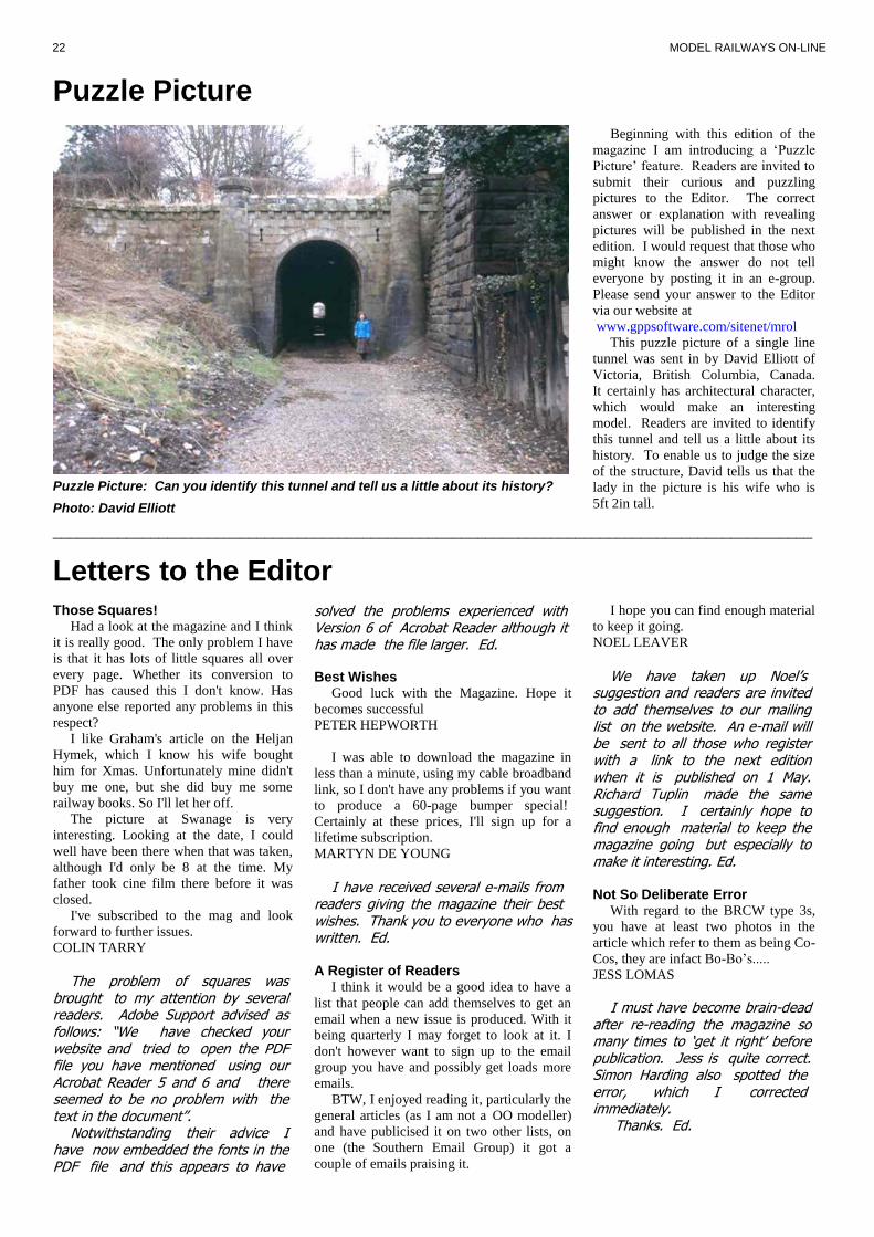
This puzzle picture of a single line
tunnel was sent in by David Elliott of
Victoria, British Columbia, Canada.
It certainly has architectural character,
which would make an interesting
model. Readers are invited to identify
this tunnel and tell us a little about its
history. To enable us to judge the size
of the structure, David tells us that the
lady in the picture is his wife who is
5ft 2in tall.
Puzzle Picture: Can you identify this tunnel and tell us a little about its history?
Photo: David Elliott


