Form RZ 415, Mfg No. 179301, Page 1 APPLIES TO: Installation/Operation/Maintenance INSTALLATION FORM RZ-NA 415 (Version A) Obsoletes Form RZ 415 GENERAL The procedures in this manual should only be performed by a qualified HVAC technician and in compliance with all codes and requirements of authorities having jurisdiction. The instructions in this manual apply to: Model PCCA, rooftop packaged cooling system with DX cooling coil Model PCDA, rooftop packaged cooling system with DX cooling coil and a dehumidifying heat pump Heat Options available on cooling Models PCCA and PCDA: • Heat Coil Module (hot water or steam coil is either factory or field supplied) • Gas-Fired Furnace (equivalent to Reznor ® Model HRP) - either natural or propane gas • Heat Coil Module (hot water or steam coil is either factory or field supplied) and a Gas Fired Furnace This booklet includes installation, startup, operation, and main- tenance information. It also includes all optional component in- Model Series PCCA and PCDA Outdoor Makeup Air Cooling and Dehumidifying Packaged Systems (Heating Optional) GENERAL ................................................... 1 INSTALLATION & OPERATION ....... 2-59 1. Approval and Installation Codes ............... 2 2. Warranty ...................................................... 2 3. Warnings ...................................................... 2 4. Uncrating and Preparation ......................... 3 Shipped-Separate Parts ....................................... 3 Storage ................................................................ 3 5. Technical Data .............................................. 4 6. Dimensions ............................................. 5-11 PCCA 060, 096; PCDA 087, 123 ....................... 5 PCCA 120, 130, 135, 150, 160; PCDA 142, 162, 176, 177, 206 ......................................... 6 PCCA 180, 195, 210, 225; PCDA 226, 241, 256, 271 .......................................................... 7 PCCA 165, 170; PCDA 223, 228 ....................... 8 PCCA 190, 215; PCDA 268, 293 ....................... 9 PCCA 240, 277; PCDA 298, 335 ..................... 10 PCCA 360; PCDA 438 ...................................... 11 7. Clearances .................................................. 12 8. Mounting .............................................. 12-18 Location and Weights ....................................... 12 Curb Cap Base .................................................. 13 Mounting on Field supplied Supports ......... 13-14 Mounting on a Roof Curb ........................... 14-16 Bottom Openings .............................................. 16 Rigging and Lifting ..................................... 17-18 9. Condensate Drains ..................................... 19 Drain Trap ......................................................... 19 10. Screened Inlet Air and Barometric Relief Hood Options ......................... 19-21 Dimensions and Installation - Opt AS2 ....... 19-20 Dimensions and Installation - Opt ASB1 ......... 20 Dimensions and Installation - Opt AS16 ..... 20-21 11. Duct Connections ..................................... 21 12. Electrical Supply and Controls ......... 22-31 Disconnect Switch ............................................ 22 Through-the-Base Access ................................. 22 Voltage Supply .................................................. 22 Supply Wiring Size ...................................... 23-24 Control Locations ............................................. 25 Cooling Controls (Standard) ............................. 26 Sequence of Operation - PCCA & PCDA .. 26-27 Optional Cooling Controls ........................... 27-29 Electrical Data (Amp Loads) ............................ 29 Typical Wiring Diagram - PCCA ..................... 30 Typical Wiring Diagram - PCDA ..................... 31 13. Blower Motor ........................................... 32 14. Condenser Fan Motors ............................ 32 18. Cooling Refrigeration System ........... 33-37 Optional Hot Gas Bypass .................................. 33 Compressors ................................................. 33-36 Dehumidifying - PCDA only ...................... 36-37 16. Blowers, Belts and Drives ...................... 37 Adjusting Blower Speed ................................... 37 Blower Rotation ................................................ 37 17. Airflows and Pressure Drops ........... 38-39 Airflow Range - Cooling only .......................... 38 Airflow Range - Cooling & Heating ................. 38 Pressure Drop Table ..................................... 38-39 OPTIONAL EQUIPMENT AND ACCESSORIES ............................. 40-46 Gas Furnace .............. Use Form 415/416-GF (NOTE: Booklet is in the Owner's Envelope) 18. Optional Cooling Coil Bypass ........... 40-41 19. Dampers ................................................ 4142 Damper Option Identification ....................... 41 Discharge ...................................................... 41 Outside and Return Inlet Air ................... 41-42 20. Hydronic Heat Coil Module .............. 42-43 Hot Water Coil Module .................................... 42 Steam Coil Module ........................................... 43 21. Optional Evaporative Cooling Module - PCCA only ........................ 43-46 22. Energy Recovery Preconditioner ........... 46 CHECK-TEST-STARTUP ................... 47-52 23A. Prior to Startup - should be done 24 hours prior to actual startup ............ 47 23B. Startup (ambient temperature above 68°F/20°C) .................................... 47 23C. After Startup ......................................... 48 23D. Special Startup (ambient temperature below 68°F/20°C) .............. 48 23E. After Special Startup ............................ 49 24. Summary of Control Settings ........... 50-51 MAINTENANCE AND SERVICE ..... 52-64 25. Maintenance Requirements .................... 52 Maintenance Schedule ...................................... 52 26. Filters .................................................. 52-53 27. Drive Components ................................... 53 28. Coil Maintenance ............................... 53-54 29. Check Refrigerant Pressure and Temperatures .......................................... 54 30. Compressor Maintenance and Replacement Instructions ................ 54-60 Handling ........................................................... 54 Replacement P/N's ............................................ 55 Oil Charge ......................................................... 56 Brazing Recommendations ............................... 57 Crankcase Heaters ............................................ 58 Voltage Utilization Range ................................. 58 Compressor Protection ...................................... 60 31. Thermal Expansion Valves ...................... 60 32. Troubleshooting ................................. 61-63 General Refrigeration Circuit ...................... 61-62 Optional Furnace ......................................... 62-63 Optional Evaporative Cooling Module ............ 63 INDEX BY PAGE NO. .............................. 64 RECORD OF JOB .................................... 64 Table of Contents Page Page Page formation except the gas furnace. If the system being installed includes an optional gas furnace, use Form RZ-NA 415/416-GF with this manual. Both manuals are in the owner's envelope. If the system includes installation of a Model ERSA energy recov- ery preconditioner, follow the instructions in Form 480 shipped with the energy recovery unit. If any applicable manual is miss- ing, contact your distributor before beginning installation.
Transcript
Form RZ 415, Mfg No. 179301, Page 1
APPLIES TO: Installation/Operation/Maintenance
INSTALLATION FORM RZ-NA 415 (Version A)Obsoletes Form RZ 415
GENERALThe procedures in this manual should only be performed by aqualified HVAC technician and in compliance with all codesand requirements of authorities having jurisdiction.
The instructions in this manual apply to:
Model PCCA, rooftop packaged cooling system with DXcooling coil
Model PCDA, rooftop packaged cooling system with DXcooling coil and a dehumidifying heat pump
Heat Options available on cooling Models PCCA and PCDA:• Heat Coil Module (hot water or steam coil is either factory
or field supplied)• Gas-Fired Furnace (equivalent to Reznor® Model HRP) -
either natural or propane gas• Heat Coil Module (hot water or steam coil is either factory
or field supplied) and a Gas Fired Furnace
This booklet includes installation, startup, operation, and main-tenance information. It also includes all optional component in-
Model Series PCCA and PCDAOutdoor Makeup Air Cooling and
Dehumidifying Packaged Systems(Heating Optional)
GENERAL ................................................... 1INSTALLATION & OPERATION ....... 2-591. Approval and Installation Codes ............... 22. Warranty ...................................................... 23. Warnings ...................................................... 24. Uncrating and Preparation ......................... 3
Shipped-Separate Parts ....................................... 3Storage ................................................................ 3
5. Technical Data .............................................. 46. Dimensions ............................................. 5-11
Location and Weights ....................................... 12Curb Cap Base .................................................. 13Mounting on Field supplied Supports ......... 13-14Mounting on a Roof Curb ........................... 14-16Bottom Openings .............................................. 16Rigging and Lifting ..................................... 17-18
13. Blower Motor ........................................... 3214. Condenser Fan Motors ............................ 3218. Cooling Refrigeration System........... 33-37
Optional Hot Gas Bypass .................................. 33Compressors ................................................. 33-36Dehumidifying - PCDA only ...................... 36-37
17. Airflows and Pressure Drops ........... 38-39Airflow Range - Cooling only .......................... 38Airflow Range - Cooling & Heating ................. 38Pressure Drop Table ..................................... 38-39
21. Optional Evaporative CoolingModule - PCCA only ........................ 43-46
22. Energy Recovery Preconditioner ........... 46
CHECK-TEST-STARTUP ................... 47-5223A. Prior to Startup - should be done
24 hours prior to actual startup ............ 4723B. Startup (ambient temperature
above 68°F/20°C) .................................... 4723C. After Startup ......................................... 4823D. Special Startup (ambient
temperature below 68°F/20°C) .............. 4823E. After Special Startup ............................ 4924. Summary of Control Settings ........... 50-51
MAINTENANCE AND SERVICE ..... 52-6425. Maintenance Requirements .................... 52
INDEX BY PAGE NO. .............................. 64
RECORD OF JOB .................................... 64
Table of Contents Page Page Page
formation except the gas furnace. If the system being installedincludes an optional gas furnace, use Form RZ-NA 415/416-GFwith this manual. Both manuals are in the owner's envelope. Ifthe system includes installation of a Model ERSA energy recov-ery preconditioner, follow the instructions in Form 480 shippedwith the energy recovery unit. If any applicable manual is miss-ing, contact your distributor before beginning installation.
Label4 = Moving Parts Warning Label6 = Air Direction Label7 = Blower Motor Replacement Label8 = Blower Rotation Label9 = Voltage Identification Label10 = Line Voltage Label*11 = Service Warning Label12 = General Warning Label13 = Wiring Notice Label18 = Electrical Connection Label
GENERAL (cont'd)Before beginning any procedure, carefully review the information, pay-ing particular attention to cautions and warnings.
Procedures requiring the handling of refrigerant should only be per-formed by a qualified HVAC technician in compliance with all codesand requirements of authorities having jurisdiction.
WARNINGAll Model PCCA and Model PCDA systemscontain chlorodifluoromethane (HCFC-22), asubstance that is believed to harm the publichealth and environment by destroying ozone inthe upper atmosphere.Do not release HCFC-22 to the atmosphere. TheU. S. Clean Air Act requires the recovery of anyresidual refrigerant.
(with heat section only)22 = Service Clearance (with heat
section only)23 = Gas Connection (with heat
section only)24 = Green Ground Label* Label on both sides of the unit
1. Approval and Installation CodesModel PCCA and Model PCDA packaged systems are certified by ETLto Heating Cooling Equipment (latest edition), UL 1995 / CAN/CSAC22.2 No. 236. Electrical characteristics are shown on the system rat-
ing plate. All cooling and dehumidifying circuits are factory-chargedwith R-22 refrigerant.If a gas furnace heat option is ordered, the system includes a power-vented gas-fueled duct furnace(s) that is design-certified to ANSI Stan-dard Z83.8a by the Canadian Standards Association. The furnace isapproved for use with either natural or propane gas. The type of gas forwhich the furnace is equipped and the correct firing rate are shown onthe furnace section rating plate (See Figure 1, Item 21).
These packaged systems must be installed in accordance with localbuilding codes. Consult local authorities having jurisdiction before in-stallation to verify local codes and installation procedure requirements.
2. WarrantyRefer to limited warranty information on the warranty form in the"Owner's Envelope" shipped with this system. If an optional extendedwarranty applies, keep the extended warranty card for future referenceand verification of warranty.
3. WarningsThere are warning labels on the unit and throughout this manual. Foryour safety, comply with all warnings during installation, operation,and service of this system. See Warning on the left and Hazard Inten-sity Levels in Figure 1.
Form RZ 415, Mfg No. 179301, Page 3
4. Uncrating and PreparationThis system was test operated and inspected at the factory prior to crating and was in operating condition. If the equipment has incurred any damagein shipment, document the damage with the carrier and immediately contact your Reznor distributor.
Check the entire unit for damage paying particular attention to the structural integrity of the strut, points of attachment of the lifting rings, and thecondenser fan section on the top of the unit.
• Lifting Rings (for location, see illustration in Figure 10, page 18) - Inspect the points of attachment of the lifting rings. If there is any doubtabout the integrity of the lifting rings, document the damage with the carrier and contact the distributor.
• Strut - Inspect all of the strut. If there is any doubt about the structural integrity of the strut, document the damage with the carrier and contactthe distributor.
• Condenser Fan Section (see Figure 1, page 2) - On the top of the system, check the condenser fan guards and fan blades. If there is any damageto the fan guards or if the blades are not at the proper height, document the damage with the carrier and contact the distributor.
Check the rating plate (sample below; location in Figure 1, Item 19) found in the blower section for the specifications and electrical characteristicsto be sure that they are compatible with the electric supply at the installation site. IMPORTANT NOTE: Do not attempt to remove any doorpanels other than the blower section or heater section. After the unit is in place, bolts must be removed to allow clearance for door removal.
If the system includes optional heating, check the rating plate on thefurnace section to be sure that it is compatible with the gas supply atthe installation site. The furnace rating plate is located on the electricalbox in the heater control compartment (See Figure 1, Item 21).
Read this booklet and become familiar with the installation require-ments of your particular model. If you do not have knowledge of localrequirements, check with the local agencies who might have require-ments concerning this installation. Before beginning, make prepara-tions for necessary supplies, tools, and manpower.
Shipped-Separate PartsCheck for shipped-separate parts. Optional dehumidification controls,room relative humidity sensor or outside air temperature override, areshipped separately for field installation. If a remote console and/or dis-connect switch are ordered, they will be shipped separately. If the sys-
tem includes optional heat, some gas control options have parts eithershipped loose with the heater or shipped separately. If there is an op-tional heater section and it is equipped with gas control Option AG15,AG16, AG17, AG18, AG9, AG39, or AG41, check for shipped-sepa-rate controls.
Other shipped-separate options could include a roof curb, a screenedoutside air hood, or a fill and drain kit for an optional evaporativecooling module, or a gas shutoff valve, a thermostat, or a gas supplyregulator for an optional furnace section.
StorageIf the system is going to be stored (either on the ground or on the roofcurb), take precautions to prevent condensate formation inside the elec-trical compartments and motors.
Rating Plate Key:
A = Model
B = Manufacturing Date (Month/Year)
C = Blower Motor HP
D = Volts/Phase/Hertz
E = Full Load Amps of BlowerMotor
F = Minimum Circuit Ampacity
G = Maximum Fuse Size
H = Quantity - Compressor A
I = Rated Load Amps ofCompressor A
J = Locked Rotor Amps ofCompressor A
K = Quantity - Compressor B
L = Rated Load Amps ofCompressor B
M = Locked Rotor Amps ofCompressor B
N = Quantity - Compressor C
O = Rated Load Amps ofCompressor C
P = Locked Rotor Amps ofCompressor C
Q = Quantity - Compressor D
R = Rated Load Amps ofCompressor D
Figure 2 - Sample Rating Plate
PCCA or PCDA MADE IN USAFOR INDUSTRIAL/COMMERCIAL USE ONLYSUITABLE FOR OUTDOOR USEMODEL [ A ] [ B ]SERIAL NO. [ ]
CIRCUITS A B C DREFRIGERANT - R-22 CHARGE - LBS [ V ] [ W ] [ X ] [ Y ]TEST PRESSURES HIGH [ AA ] PSIG LOW [BB ] PSIGEQUIPPED FOR OPERATION AT AN AIR FLOW OF [ CC ] SCFMAGAINST A STATIC PRESSURE OF [ DD ] INCHES WATER COLUMN.DRIVE RPM [ EE ]WIRE DIAGRAM [ FF ]
REFER TO RATING PLATE IN THE FURNACE SECTION(WHEN USED)FOR ADDITIONAL INFORMATION.
*HACR TYPE REQUIRED PER NEC
ELECTRICAL
REZNOR MERCER, PA., U.S.A. 16137 S = Locked Rotor Amps of
Compressor D
T = Quantity Condenser Fan Motors
U = Rated Load Amps of Condenser(s)
V = Refrigerant Charge (lbs) - Circuit A
W = Refrigerant Charge (lbs) - Circuit B
X = Refrigerant Charge (lbs) - Circuit C
Y = Refrigerant Charge (lbs) - Circuit D
Z = Condenser Fan Motor HP
AA = Test Pressure High (psig)
BB = Test Pressure Low (psig)
CC = SCFM Airflow
DD = External Static Pressure (inches w.c.)
EE = Drive (Option AM)
FF = Wiring Diagram No.
Form RZ 415, Mfg No. 179301, Page 4
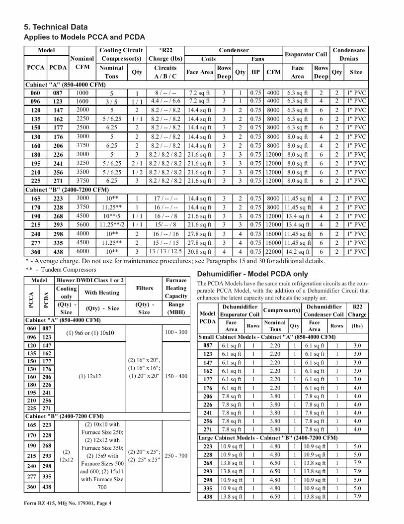
5. Technical DataApplies to Models PCCA and PCDA
Dehumidifier - Model PCDA onlyThe PCDA Models have the same main refrigeration circuits as the com-parable PCCA Model, with the addition of a Dehumidifier Circuit thatenhances the latent capacity and reheats the supply air.
Nominal Tons
QtyCircuits A / B / C
Face AreaRows Deep
Qty HP CFMFace Area
Rows Deep
Qty Size
Cabinet "A" (850-4000 CFM)060 087 1000 5 1 8 / -- / -- 7.2 sq ft 3 1 0.75 4000 6.3 sq ft 2 2 1" PVC
(2) 15x9 with Furnace Sizes 500 and 600; (2) 15x11 with Furnace Size
700
Furnace Heating Capacity
100 - 300
250 - 700
150 - 400
FiltersBlower DWDI Class 1 or 2Model
PC
CA
PC
DA
R22 Charge
Face Area
RowsNominal
TonsQ ty
Face Area
Rows (lbs)
Small Cabinet Models - Cabinet "A" (850-4000 CFM)
087 6.1 sq ft 1 2.20 1 6.1 sq ft 1 3.0
123 6.1 sq ft 1 2.20 1 6.1 sq ft 1 3.0
147 6.1 sq ft 1 2.20 1 6.1 sq ft 1 3.0
162 6.1 sq ft 1 2.20 1 6.1 sq ft 1 3.0
177 6.1 sq ft 1 2.20 1 6.1 sq ft 1 3.0
176 6.1 sq ft 1 2.20 1 6.1 sq ft 1 4.0
206 7.8 sq ft 1 3.80 1 7.8 sq ft 1 4.0
226 7.8 sq ft 1 3.80 1 7.8 sq ft 1 4.0
241 7.8 sq ft 1 3.80 1 7.8 sq ft 1 4.0
256 7.8 sq ft 1 3.80 1 7.8 sq ft 1 4.0
271 7.8 sq ft 1 3.80 1 7.8 sq ft 1 4.0
Large Cabinet Models - Cabinet "B" (2400-7200 CFM)
223 10.9 sq ft 1 4.80 1 10.9 sq ft 1 5.0
228 10.9 sq ft 1 4.80 1 10.9 sq ft 1 5.0
268 13.8 sq ft 1 6.50 1 13.8 sq ft 1 7.9
293 13.8 sq ft 1 6.50 1 13.8 sq ft 1 7.9
298 10.9 sq ft 1 4.80 1 10.9 sq ft 1 5.0
335 10.9 sq ft 1 4.80 1 10.9 sq ft 1 5.0
438 13.8 sq ft 1 6.50 1 13.8 sq ft 1 7.9
Model PCDA
Compressor(s)Dehumidifier
Evaporator CoilDehumidifier
Condenser Coil
Form RZ 415, Mfg No. 179301, Page 5
6. Dimensions
Figure 3B - Models PCCA 060, 096 - with Two Gas Furnace Sections (Size 300) or One Gas Furnace Size 200 or 225 anda Hydronic Heat Coil Module (for factory or field supplied hot water or steam coil)Model PCDA 087, 123 - with Two Gas Furnace Sections (Size 300) or One Gas Furnace Size 200 or 225 anda Hydronic Heat Coil Module (for factory or field supplied hot water or steam coil)
Figure 3A - Models PCCA 060, 096 - Standard Cabinet (no heat); with One Gas Furnace (Size 100, 125, 150, 175, 200,or 225); or with a Hydronic Heat Coil Module (for factory or field supplied hot water or steam coil)Model PCDA 087, 123 - Standard Cabinet (no heat); with One Gas Furnace (Size 100, 125, 150, 175, 200, or225); or with a Hydronic Heat Coil Module (for factory or field supplied hot water or steam coil)
Figure 3C - Models PCCA 120, 135, 150, 130, 160 - Standard Cabinet (no heat); with One Gas Furnace (Size 150, 175,200, or 225); or with a Hydronic Heat Coil Module (for factory or field supplied hot water or steam coil)Models PCDA 147, 162, 177, 176, 206 - Standard Cabinet (no heat); with One Gas Furnace (Size 150, 175,200, or 225); or with a Hydronic Heat Coil Module (for factory or field supplied hot water or steam coil)
Figure 3D - Models PCCA 120, 135, 150, 130, 160 with Two Gas Furnace Sections (Size 300 or 400) or One Gas FurnaceSize 200 or 225 and a Hydronic Heat Coil Module (for factory or field supplied hot water or steam coil)Models PCDA 147, 162, 177, 176, 206 with Two Gas Furnace Sections (Size 300 or 400) or One Gas-FurnaceSize 200 or 225 and a Hydronic Heat Coil Module (for factory or field supplied hot water or steam coil)
Figure 3E - Models PCCA 180, 195, 210, 225 - Standard Cabinet (no heat); One Gas Furnace (Size 150, 175, 200, or225); or a Hydronic Heat Coil Module (for factory or field supplied hot water or steam coil)Models PCDA 226, 241, 256, 271 - Standard Cabinet (no heat) or One Gas Furnace (Size 150, 175, 200, or225); or a Hydronic Heat Coil Module (for factory or field supplied hot water or steam coil)
Figure 3F - Models PCCA 130, 160, 180, 195, 210, 225 with Two Gas Furnace Sections (Size 300 or 400) or One Gas-Furnace Size 200 or 225 and a Hydronic Heat Coil Module (for factory or field supplied hot water or steamcoil)Models PCDA 176, 206, 226, 241, 256, 271 with Two Gas Furnace Sections (Size 300 or 400) or One Gas-Furnace Size 200 or 225 and a Hydronic Heat Coil Module (for factory or field supplied hot water or steamcoil)
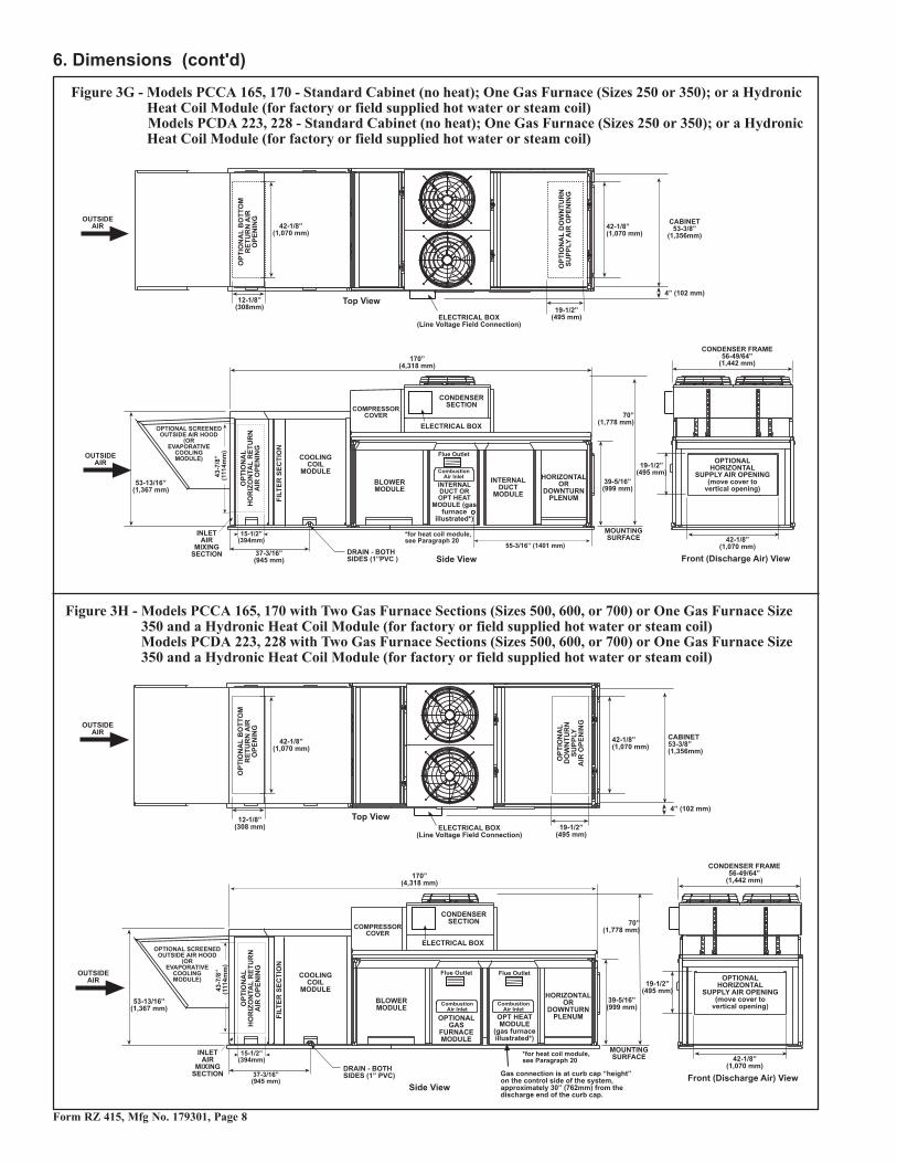
Figure 3G - Models PCCA 165, 170 - Standard Cabinet (no heat); One Gas Furnace (Sizes 250 or 350); or a HydronicHeat Coil Module (for factory or field supplied hot water or steam coil)Models PCDA 223, 228 - Standard Cabinet (no heat); One Gas Furnace (Sizes 250 or 350); or a HydronicHeat Coil Module (for factory or field supplied hot water or steam coil)
Figure 3H - Models PCCA 165, 170 with Two Gas Furnace Sections (Sizes 500, 600, or 700) or One Gas Furnace Size350 and a Hydronic Heat Coil Module (for factory or field supplied hot water or steam coil)Models PCDA 223, 228 with Two Gas Furnace Sections (Sizes 500, 600, or 700) or One Gas Furnace Size350 and a Hydronic Heat Coil Module (for factory or field supplied hot water or steam coil)
Figure 3J - Models PCCA 190, 215 - Standard Cabinet (no heat); One Gas Furnace (Size 250 or 350); or a HydronicHeat Coil Module (for factory or field supplied hot water or steam coil)Models PCDA 268, 293 - Standard Cabinet (no heat); One Gas Furnace Section (Size 250 or 350); or aHydronic Heat Coil Module (for factory or field supplied hot water or steam coil)
Figure 3K - Models PCCA 190, 215 with Two Gas Furnace Sections (Sizes 500, 600, 700); or One Gas Furnace Size350 and a Hydronic Heat Coil Module (for factory or field supplied hot water or steam coil)Models PCDA 268, 293 with Two Gas Furnace Sections (Sizes 500, 600, 700); or One Gas Furnace Size350 and a Hydronic Heat Coil Module (for factory or field supplied hot water or steam coil)
Figure 3M - Models PCCA 240, 277 with Two Gas Furnace Sections (Size 500, 600, or 700); or One Gas Furnace Size350 and a Hydronic Heat Coil Section (for factory or field supplied hot water or steam coil)Models PCDA 298, 335 with Two Gas Furnace Sections (Size 500, 600, or 700); or One Gas Furnace Size350 and a Hydronic Heat Coil Module (for factory or field supplied hot water or steam coil)
Figure 3L - Models PCCA 240, 277 - Standard Cabinet (no heat); One Gas Furnace (Size 250 or 350); or a HydronicHeat Coil Module (for factory or field supplied hot water or steam coil)Models PCDA 298, 335 - Standard Cabinet (no heat); One Gas Furnace (Size 250 or 350); or a HydronicHeat Coil Module (for factory or field supplied hot water or steam coil)
Figure 3P - Models PCCA 360 with Two Gas Furnace Sections (Size 500, 600, or 700); or One Gas Furnace Size 350and a Hydronic Heat Coil Module (for factory or field supplied hot water or steam coil)Models PCDA 438 with Two Gas Furnace Sections (Size 500, 600, or 700); or One Gas Furnace Size 350and a Hydronic Heat Coil Module (for factory or field suplied hot water or steam coil)
Figure 3N - Models PCCA 360 - Standard Cabinet (no heat); One Gas Furnace (Size 250 or 350); or a Hydronic HeatCoil Module (for factory or field supplied hot water or steam coil)Models PCDA 438 - Standard Cabinet (no heat); One Gas Furnace (Size 250 or 350); or a HydronicHeat Coil Module (for factory or field supplied hot water or steam coil)
7. ClearancesProvide minimum clearances as shown in Figure 4. Minimum clearances are required to ensure proper operation and access for service. If optionalheating is included, clearances to combustibles are required. Clearance to combustibles is defined as the minimum distance from the heater to asurface or object that is necessary to ensure that a surface temperature of 90°F above the surrounding ambient temperature is not exceeded.Because of the condenser sections, above the unit must always be open.
Figure 4 - Clearances
8. MountingLocation and WeightsApproximate Net Weight of Cooling Only System (lbs and kg)
IMPORTANT CLEARANCE NOTES:• Condenser coils and fans are mounted on top of the system. Provide unrestricted clearance over the condenser fans for discharge and
around the condenser section for air inlet.• Assure diffusion of exhaust air from any sources before air enters the outside air inlet. Check local codes for requirement on distance
Curb Cap BaseThe system is equipped with a load bearing curb cap which formsan integral part of the unit. This curb cap has bolted seams andhas a "skirt" which fits over a roof curb or support rails. The curbcap is not designed to be placed directly on the roof surface.The system may be mounted on an optional roof curb purchasedwith the unit, a field supplied roof curb, or field supplied supportrails. On a roof, a roof curb is recommended to provide a weath-erproof installation as well as additional clearances for ductwork.
Model PCCA and PCDA systems may be mounted on roofs withrails or roof curbs or on cement slabs with rails. When the unit isbeing placed on a roof, location depends on the roof structure. Ifinstalling more than one system, it is recommended to minimizestructural span deflection to discourage sound transmission.Position the unit so that the air inlet will not be facing into theprevailing wind. Always comply with the clearances in Paragraph7. For condensate drainage and proper operation, it is importantthat the installation be level.
Approximate Net Weight of Cooling System with Gas Furnace and Hydronic Heat Coil Modules (lbs and kg)
Mounting on Field Supplied Supports (without a roofcurb) - Figures 6 and 7Prior to installation, be sure that the method of support is in agreement withall local building codes and is suited to the climate. If considering this typeof installation in snow areas, it is recommended that the 4x4 wooden railsunder the system be on a cross supported structure (see Figure 7) at least12" (305mm) higher than the roof surface. IMPORTANT NOTE: If set-ting rails or cross support on roof surface and not decking, be sure to havesufficient tread material under the rails or supports to adequately spread theload and prevent "sinking" into the roofing material.
Whether the supports are being mounted directly on the roof or being placed"up" on an additional structure, the horizontal length of the system shouldbe supported by two 4x4 treated wooden rails. Cut the rails to the appropri-ate length (Dimension "A") in Figure 6.
Space the 4x4 wooden rails (See "B" Dimension, Figure 6) so that the curbcap "skirt" (See Figure 5) will fit over the edge of the boards with the railssetting inside the horizontal length of the curb cap.
If the rails are being laid directly on the roof, position them as shown inFigure 6. Set the system on the rails, leaving the "ends" underneath open forventilation.
If the treated wooden rails are not being placed directly on the roof surface,cross supports should be placed under the rails at the ends of the unit and atall cabinet "joints". See Figure 7, page 14.
The field supplied, weather resistant cross support structure must be ad-equate for the weight of the system (Refer to weights on page 12.) and allcross-supports should extend beyond the width of the system supportingthe 4x4 wooden rails at the recommended locations.
Detailed Views of Curb Cap onWooden Rails and Cross Supports
Mounting on a Roof Curb - Figure 8AThe optional curb is a 16" fully enclosed curb as illustrated in Figure8A. If the application is sound sensitive, consider installing a fieldsupplied vibration isolation curb or specialty sound attenuation curb.
Whether using the optional roof curb available with the system or afield supplied curb, the curb must be secure, square, and level.
The top surface of the roof curb must be caulked with 1/4" x 1-1/4"sealant tape or two 1/4" beads of suitable sealant. The unit must besealed to the curb to minimize sound transmission, prevent air leakage,
and to prevent water leakage into the curb area due to wind blown rainand capillary action.
Except for dimensional details specific to each model, the informationand requirements in these instructions apply to all curbs.
For curb assembly and installation, see Figures 8A and 8B and followthe instructions.
IMPORTANT: If the system has a furnacesection, the area enclosed by the roof curb mustcomply with clearance to combustible materials. Ifroof is constructed of combustible materials, thearea within the curb must be either ventilated, leftopen, or covered with non-combustible materialwhich has an "R" value of at least 5.0. If the areawithin the curb is left open, higher radiated soundlevels may result.
IMPORTANT:To minimize
sound transferand prevent air
and waterleakage, the topsurface of curb
MUST besealed.
88�����<
��
��
Roof Curb Assembly and Installation Instructions (Refer to Figures 8A and 8B)Curbs are shipped unassembled. Field assembly and mounting on the roof are the responsibility of the installer. All hardware necessary to assemblethe curb is supplied. Any additional hardware must be field supplied.
Before installing roof curb, verify that the size is correct for the system being installed.1. Position curb cross rails and curb side rails as illustrated in Figure
8A. Each side rail is made up of two pieces. Fasten the side pieceswith splice plates and hardware as illustrated in the splicing detaildrawing in Figure 8B. Join the corners as illustrated in the cornerdetail (Figure 8B).
2. Check the assembly for squareness. Adjust the roof curb so that thediagonal measurements are equal within a tolerance of + or - 1/8".
3. Level the roof curb. To ensure proper condensate drainage and aweathertight seal between the curb cap and the roof curb, the roof
curb must be leveled in both directions with no twist end to end.Shim level as required and secure curb to roof deck before pro-ceeding with flashing.
4. Install field supplied flashing.5. Before placing the unit into position, apply furnished 1/4" x
1-1/4" foam sealant tape to top surface of curb, making good buttjoint at corners. The unit must be sealed to the curb to preventwater leakage into the curb area due to blown rain and capillaryaction.
Bottom OpeningsThe system has an optional return air opening and a choice of avertical or horizontal supply air opening. If optional return airdampers are not ordered, the unit is shipped with a cover on thereturn air opening. During shipment, a cover is always on thehorizontal discharge (supply air) opening.
If return air is being used in the installation, remove the returnair opening cover. This can be done right away or anytime priorto startup procedure. Or, if needed to further balance outsideand return air, the cover can be modified to decrease the size ofthe return air opening. When restricting return air, always blockthe side closest to the filter leaving the full width toward theoutside air entrance open.
If the installation requires horizontal discharge (supply air), re-move the cover from the horizontal opening. Inside the down-turn plenum, position the cover over the bottom discharge open-ing; attach it using the same screws. NOTE: If the cover is leftin the horizontal position, seal around the cover plate to avoidany air or water leaks.
Both the return air and supply air bottom openings have ductflanges for connection to ductwork using a flexible ductworkconnector. Duct opening sizes are shown in Figure 8C, page 16.Curb spacing shown in Figure 8C is for currently manufacturedcurbs that are available from the system manufacturer.
After Unit is Mounted Before Proceeding with Installation
Rigging and Lifting (Refer to Figure 10, page 18)
DANGER: If there is any visible damage or any question about the integrity of the strut or the liftingrings, do not lift the system. Consult the factory. See Hazard Intensity Levels, page 2.
See approximate net weights on page 12. If required, approximate cor-ner weights are available from the manufacturer.
If the unit is being mounted on a roof curb, apply gasketing to the roofcurb prior to lifting the unit to the roof and setting it on the curb. SeeFigure 8A and detailed drawing in Figure 8B.
Lifting rings are provided for rigging. Refer to the illustration in Figure10, page 18, and locate the lifting rings. Inspect the rings and theirattachment points. If there is any doubt about the integrity of the liftingrings or their attachment points, contact the factory.
On PCCA Sizes 165, 170, 190, 215, 240, 277 and 360 and PCDA Sizes223, 228, 268, 293, 298, 335, and 438, if the compressor cover wasinstalled at the factory, it will be necessary to remove it to access thelifting rings toward the inlet end of the system (See Figure 10, page 18).Remove the four screws on each side (save screws for re-attaching thecover). Lift the cover up and off; lifting rings are now accessible. Liftcover separately from the system; re-install after unit is in place. NOTE:The more common procedure on these large units is for the compressorcover to be shipped unattached. The cover must then be attached afterthe unit is lifted.
To minimize the possibility of tubing damage during lifting, removethe compressor shipping supports before lifting. Always maintain clear-ances between the rigging and copper tubing and/or electrical con-duit. To prevent chains or cables from damaging the condenser coilcasing, the use of spreader bars is recommended. If the circumstancesrequire a rigging height that is less than 12 feet (3.7M), spreader barsare required.
Test lift the unit to be sure that it is secure. Lift the unit slowly, follow-ing safe lifting procedures.
Failure to lift by the manufacturer's instructions could cause damageto the equipment and/or personal injury or death. The equipment manu-facturer is not responsible for unsafe rigging or lifting procedures.
DANGER: To prevent injury, death, orequipment damage caused by inadequate orimproper rigging, test-lift the unit beforeattempting to install it on the roof. See HazardIntensity Levels, page 2.
IMPORTANT: After unit is mounted but before door panels (coilsection, inlet air section, filter section, or discharge plenum) are re-moved, remove bolts from the bottom of the vertical strut supports asillustrated in Figure 9.
WARNING: After system is in place, remove onlybolts indicated. Do not remove any other bolts.
Figure 9 - AFTER SYSTEM IS IN PLACE, at bottom ofeach vertical strut support, remove the bolt that runsparallel with the cabinet
Sizes PCCA 165, 170, 190, 215, 240, 277 and 360 and PCDA Sizes223, 228, 268, 293, 298, 335, and 438) - Attach the compressor coverafter the unit is in place.
If the system includes an outside air hood and/or a barometric damperhood, attach it after the unit is in place. Follow the directions in Para-graph 10. (This may be done now or later but not before the unit islifted.)
Remove bolt on strutsupport betweencabinet sections
DANGER: To prevent injury,death, or equipment damagecaused by inadequate or improperrigging, test lift the unit beforeattempting to install it on the roof.
8. Mounting (cont'd)Rigging and Lifting (cont'd)Figure 10 - Rigging and Lifting
1) Locate lifting rings. Attach rigging.NOTE: Model PCCA 165, 170, 190, 215, 240, 277 and 360 or PCDA 223,228, 268, 293, 298, 335, and 438 - If the compressor cover was installed atthe factory, remove it to access the two lifting rings toward the inlet end ofthe system. Replace cover after unit is lifted.
DANGER: If there is any visible damage orany question about the integrity of the liftingrings or the strut, do not continue. Consultthe factory.
Lifting Ring
2) Comply with rigging requirements shown in the illustration below plus• Remove compressor shipping supports.
• During lifting,be sure thatclearances willbe maintainedbetween therigging and thecopper tubingand the riggingand the electricalconduit.
3) Test lift the unit. Determine that the unit is se-cure. Lift the unit slowly, following safe lifting pro-cedures.Failure to lift by the manufacturer's instructions couldcause damage to the equipment and/or personal injury ordeath. The equipment manufacturer is not responsible forunsafe rigging or lifting procedures.
Form RZ 415, Mfg No. 179301, Page 19
Option AS2 Installation Instructions (Figure 13B)All screw ends except those across the bottom should be inside the airhood.
9. Condensate DrainsA 1" PVC drain connection is located on both sides of the cabinetsection that houses the evaporator coil. The coil cabinet condensatepan is fabricated for drainage using both drain outlets. Using onlyone condensate drain outlet can cause ponding in the condensate pan.Ensure the system is level and install a trap in each drain (see Figure11). Pitch each drain line at least 1/2" (13mm) for every 10 feet (3M)of horizontal run. Drain lines must not interfere with access panel re-moval.
If the installation or local code requires, run all drains into a wastewater system.
Drain TrapsThe design of the drain traps is important. Since the condensate drainpan is on the blower side, there is a negative pressure at the drain rela-tive to the ambient. The trap height must account for this static pres-sure difference. Maximum negative static can be determined by read-ing the negative pressure at the blower inlet and adding .2” w.c. toallow for dirty filters.
If dimension "B" is not tall enough, the water seal will not hold and airwill be drawn through the drain pipe into the system. If the outlet leg ofthe trap is too tall, water will back up into the drain pan. As condensateforms during normal operation, the water level in the trap rises untilthere is a constant outflow. Figure 11 illustrates the appropriate dimen-sions for trapping a negative pressure system.
Condensate Drain UseImproper trap design accounts for some condensate drainage systemfailures, but incorrect use and maintenance of condensate drain trapscan also cause problems. The combination of airborne particles andmoisture in the air handler can result in algae formation in the drainpan and traps. The traps must be cleaned regularly to avoid blockagethat can slow or stop water flow, resulting in backup into the system.
If the drains have a cleanoutopening (Figure 12), be sure toclose the opening after clean-ing.
If the condensate drains are di-rectly connected to a sewer, ad-ditional protection against sew-age gas entering the air handlermay be required. Consult withlocal building or health depart-ment codes.
Seasonal Usage - At the begin-ning of the cooling season, in-spect and clean the entire cool-ing coil cabinet including the condensate drain pan. Thoroughly cleandirt, algae, grease, and other contaminates. Inspect condensate drainpans, traps, and piping; fill traps with water to ensure proper operation.During a winter time shutdown of the cooling system it may be desir-
Figure 11 - Condensate Drain Trap Dimensions (Installdrains on both sides; install trap in both drains.)
able to disconnect and remove all water from the traps and drains toprevent freeze damage. If local building codes permit, traps may befilled with an antifreeze solution. Or, piping may be designed withfreeze plugs or other freeze protection methods (such as a heat tape).
Year Round Usage - Climates or applications with cooling require-ments year round require more frequent inspections of the cooling coilcabinet and condensate drains. Depending on climate, freeze protec-tion of traps may be required during non-cooling hours.
10. Optional Screened Inlet Air andBarometric Relief Hoods
Outside Air Hoods - The outside air hood (either Option AS2 or AS16)is a weatherized, screened hood designed to be field assembled andinstalled around the horizontal inlet air opening of the cabinet. OptionAS2 includes moisture eliminating louvers; Option AS16 includes per-manent aluminum filters.Follow the instructions that apply to the type of hood being installed.Illustrated instructions are also included in the option package.
CAUTION: It is recommended that the inlet to theoutside air hood NOT be facing into the prevailingwind. Allow 14" minimum clearance from thebottom of the air hood to the mounting surface.
Figure 13B - AssemblyDrawing of OptionAS2 OutsideAir Hood
NOTE: Width of theoutside air hood is thesame as the cabinet width.
Form RZ 415, Mfg No. 179301, Page 20
Option AS2 Installation Instructions (cont'd)
10. Optional Screened Inlet Air andBarometric Relief Hoods (cont'd)
To avoid possible damage, it is recommended that the outside air hoodbe installed after the system has been placed on the roof. The air hoodshould be installed before the blower is operated. Do not install thehood while the system is in operation.
1. Install Top Panel - On the air inlet of the cabinet, remove therow of factory-installed screws attaching the system top. Slide thehood top panel under the edge of the cabinet top. The edge of thehood top panel must be between the cabinet top and the endpanel. Reinsert all of the sheetmetal screws.
2. Install Side Panels - Slide the hood right side panel into the slotbetween the cabinet end panel and the corner leg. Be sure that theside panel is under and to the inside of the hood top panel. Attachto the cabinet and the hood top using the required number ofsheetmetal screws. Repeat with the left side panel.
3. Install Bottom Panel - Position the hood bottom panel so that itis to the inside of the two side panels and above the factory-installed support angle. Attach to both side panels.
If the bottom panel does not rest tightly against the supportangle, follow these instructions to adjust the position of thesupport angle:
a) Slightly loosen (do not remove the screws).
b) Slide the support angle up so that it is against the bottompanel.
c) Tighten the screws.
Attach the support angle to the hood bottom panel. The bottompanel of the hood and the support angle should be tight together;do not draw with the sheetmetal screws.
4. Install Louver Assembly - With the intake screen toward theinside of the hood, position the vertical louver assembly in theinlet opening of the hood. Using the remaining sheetmetalscrews, attach the louver assembly to the hood side panels at theholes provided.
10B. Option ASB1, Barometric Relief HoodTo balance building pressure, the optional barometric relief hood isdesigned to automatically open to relieve positive indoor pressure.
To avoid possible damage, it is recommended that the hood be installedafter the system has been placed on the roof. Install the barometricrelief hood before installing the outside air hood or inlet air ductwork.The barometric relief hood may be used with outside air hood OptionAS16; do not install with outside air hood Option AS2. Install thehood before the blower is operated. Do not install the hood while thesystem is in operation.
Refer to Figure 15 for installation location. Use sheetmetal screws toattach the hood over the opening.
Figure 14 -Option ASB1,BarometricRelief Hood
10C. Option AS16, Screened Outside Air Hoodwith Filters (Figures 15 and 16A or 16B)
This hood has 1" permanent filters to catch moisture. It has a lowerpressure drop than the hood with moisture-eliminating louvers (Op-tion AS2). See position and dimensions of hood in Figure 15.
Option AS16 Installation InstructionsNOTE: If installing a barometric relief damper, install it before in-stalling the screened outside air hood.To avoid possible damage, it is recommended that the outside air hoodbe installed after the system has been placed on the roof. The air hoodshould be installed before the blower is operated. Do not install thehood while the system is in operation.Option AS16 outside air hood is shipped for field assembly and instal-lation. All screw ends should be inside the air hood. Refer to the illus-trations in Figures 16A or 16B and follow the instructions below.
1. Install Top Panel - On the air inlet of the cabinet, remove thefactory-installed screws attaching the system top. Slide the hoodtop panel underneath the edge of the cabinet top. The edge of thehood top panel must be between the cabinet top and the endpanel. Reinsert all of the sheetmetal screws.
2. Install Top Panel Slope Section (applies to hood with two-piecetop only) - Position the slope section under the edge of the toppanel. Attach with sheetmetal screws.
3. Install Side Panels - Slide the hood right side panel into the slotbetween the cabinet end panel and the corner leg. Be sure that thehood side panel is under and to the inside of the hood top panelincluding the slope section. Attach to the cabinet and the hoodtop using the required number of 1/2" sheetmetal screws. Repeatwith the left side panel.
4. Install Bottom Panel - Position the hood bottom panel so that itis to the inside of the two side panels. Attach to both side panels.
5. Install the Filter Assembly - Install filter frame with filters inplace. Position the filter frame assembly in the inlet opening ofthe hood. Attach with sheetmetal screws, using four 1/2" screwsat the front and back holes and two 3/4" screws at the center holeon each side.
�
�
�
�
��������-@����������������
�����-4�"��#�������������
���������-����#����)���� �����
Figure 15 - Dimensions of both Option AS16, OutsideAir Hood with Permanent Filters, and Option ASB1,Barometric Relief Hood
Size A B C Dinches mm inches mm inches mm inches mm
11. Duct ConnectionsRequirements and Suggestions for Connecting andInstalling Ducts
• Type of Ductwork - The type of duct installation to be used dependsin part on the type of construction of the roof (whether wood joist,steelbar joist, steel truss, pre-cast concrete) and the ceiling (whetherhung, flush, etc.).
• Ductwork Material - Rectangular duct should be constructed of notlighter than No. 26 U.S. gauge galvanized iron or No. 24 B & Sgauge aluminum.
• Ductwork Structure - All duct sections 24 inches or wider, and over48 inches in length, should be cross broken on top and bottom andshould have standing seams or angle-iron braces. Joints should be Sand drive strip, or locked.
• Through Masonry Walls - No supply air duct should come in con-tact with masonry walls. Insulate around all air ducts through ma-sonry walls with not less than 1/2" (1" is recommended) of insula-tion.
• Through Uncooled/Unheated Space - Insulate all exposed supplyair ducts passing through an uncooled or unheated space with at least1/2" (1" is recommended) of insulation.
• Duct Supports - Suspend all ducts securely from adjacent buildingsmembers. Do not support ducts solely by the unit duct connections.
• Duct Sizing - Proper sizing of the supply air ductwork is necessary toensure a satisfactory installation. The recognized authority for suchinformation is the Air Conditioning Contractors Association, 122817th Street N.W., Washington, D.C. 20036. A manual covering ductsizing in detail may be purchased directly from them.
CAUTION: An external duct system staticpressure not within the limits shown on the ratingplate, or improper motor pulley or beltadjustment, may overload the motor. See HazardLevels, page 2.
• Bottom Duct Connections - To minimize sound and vibrationtransmission, always use flexible duct connections at the unit forall duct connections. Insert ducts from below roof deck throughroof opening into the unit. Gain access to the unit by removingside panels from the cabinet sections. Ducts must be attached andsealed to provide airtight connections.
Installation NOTE: If bottom discharge duct connection is used,seal around the horizontal connection cover plate to avoid any airor water leaks.
• Supply Air Duct Optional Horizontal Connection - If using thehorizontal duct connection, the seal between the unit and the ductshould be mechanical. Make duct connection with "U" type flangeson the top and bottom of the connecting duct. Slide the duct overthe flanges giving an airtight fit. Provide "U" type channels forthe side flanges to ensure tight joints. Use sheetmetal screws tofasten ducts and "U" channels to the flanges.
Installation NOTE: If a horizontal discharge is being used, it isnecessary to remove the cover from the opening. The cover mustthen be positioned over the vertical discharge opening. Use thesame screws to attach the cover over the opening in the bottom ofthe discharge section.
• Return Air Duct/Grill Size - Make certain that return air ductingor grills have a free area equal to the return duct size connection.
If the application requires bottom return air, be sure to remove thereturn air cover. Or, if needed to further balance outside and re-turn air, the cover can be modified to decrease the size of thereturn air opening. When restricting return air, always block theside closest to the filter leaving the full width toward the outsideair entrance open.
If the application requires horizontal return air, the seal betweenthe unit and the duct must be mechanical. Make duct connectionwith U" type flanges on the top and bottom of the connectingduct. Slide the duct over the flanges giving an airtight fit. Provide"U" type channels on the side flanges to ensure tight joints. Usesheetmetal screws to fasten ducts and "U" channels to the flanges.
Figure 16 - Installationof Outside Air Hood,Option AS16
NOTE: If filter tray is mistakenlyinstalled without filters in place,see Maintenance Section, page 53,Figure 51, for instructions oninstalling filters.
Figure 17 - Electrical Connections and Recommended Disconnect Locations
12. Electrical Supply and ControlsAll electrical wiring and connections, including electrical grounding MUST be made in accordance with the National Electric Code ANSI/NFPANo. 70 (latest edition). In addition, the installer should be aware of any local ordinances or electric company requirements that might apply.
Supply WiringCheck the tables on pages 23 and 24 and the rating plate for the supplyvoltage and current requirements. Run a separate line voltage supply withfused disconnect switch directly from the main electrical panel, makingconnection to leads in the junction box.If the system is equipped with a through-the-base electrical supply, refer tothe illustration in Figure 17.All external wiring must be within approved conduit and have a minimumtemperature rise rating of 60°C. Conduit to and from the disconnect switchmust be run so as not to interfere with the service panels.
VoltageThe electric supply to the unit must meet stringent requirements for thesystem to operate properly. Voltage supply and voltage imbalance betweenphases should be within the tolerances listed below. If the power is notwithin these voltage tolerances, contact the power company prior to operat-ing the system.
Voltage Supply - See voltage use range on the rating plate. Measure (andrecord) each supply leg voltage at all line disconnect switches. Readingsmust fall within the allowable range on the rating plate.
Voltage Imbalance - In a 3-phase system, excessive voltage imbalance be-tween phases will cause motors to overheat and eventually fail. Maximumallowable imbalance is 2%. To determine voltage imbalance, use recordedvoltage measurements in this formula.
Key: V1, V2, V3 = line voltages as measured
VA (average) = (V1 + V2 + V3) / 3
VD = Line voltage (V1, V2, or V3) that deviates farthest fromaverage (VA)
Formula: % Voltage Imbalance = [100 x (VA-VD)] / VA
If the system was ordered with a voltage safety switch (Option BF14) thatmonitors for phase loss or low voltage, the circuit to the compressors willbe opened in the event of phase loss or low voltage. In six minutes, theswitch will recheck the voltage. If the problem is eliminated, the circuit isre-activated.
Disconnect SwitchA disconnect switch is a required part of this installation. Refer tothe supply wiring tables on pages 23 and 24 for electrical require-ments by Model and size. Disconnect switches are available, asoptions or parts, or may be purchased locally. When ordered as anoptional component, the disconnect switch is shipped separately.See Figure 17 for the recommended mounting locations. Use fieldsupplied braces and hardware to attach the disconnect switch tothe strut; do not attach the disconnect switch directly to thesheetmetal housing. When running electrical conduit, be carefulthat it is clear of all access panels and the flue outlet on an op-tional furnace section. If installing the disconnect switch elsewhere,it is recommended that there is at least four feet (1.2M) of serviceroom between the switch and removable panels.When providing or replacing fuses in the fusible disconnect, usedual element time delay fuses and size according to the ratingplate.
WARNING: To prevent injury or death dueto electrocution or contact with moving parts,lock field supplied disconnect switch open.See Hazard Levels, page 2.
WARNING: If an optional gas furnace isincluded, if you turn off the power supply,turn off the gas. See Hazard Levels, page 2.
CAUTION: If any of the original wire assupplied with the appliance must be replaced,it must be replaced with wiring materialhaving a temperature rating of at least 105°C.See Hazard Levels, page 2.
If equipped with OptionAVC1, there is anentrance for line voltageup through the "floor"of the blower section.
A removable coveris provided for easyaccess when pullingwires.
Form RZ 415, Mfg No. 179301, Page 23
Supply Wiring Requirements by Model and Size - Model PCCA
Maximum Maximum MaximumFuse Amps Fuse Amps Fuse Amps
NOTE: Supply wiring requirements do not change with the addition of a heatsection. The tables below list requirements for the motor type with the largestFLA rating.
Form RZ 415, Mfg No. 179301, Page 24
12. Electrical Supply and Controls (cont'd)Supply Wiring Requirements by Model and Size - Model PCDA
Maximum Maximum MaximumFuse Amps Fuse Amps Fuse Amps
NOTE: Supply wiring requirements do not change with the addition of aheat section. The tables below list requirements for the motor type with thelargest FLA rating.
Form RZ 415, Mfg No. 179301, Page 25
'6 % $
5)-3
4
'2''
'%
'$'5
')
'-'3
5562
6'
666%
656)6-
63 64
%2
%'%6
%%
%$
%5%)
%-
%3%4$2
$'
$6
$%
$$ $5 $)$)
$-
$-
$3$4
52
5'
5%5'
$4
6$
56
5$
'4
$!
�8,:����8�
��8,:����8�
�
�8,:����8�
��8,:����8�
�
'6
5)
5-
DESCRIPTION1 Venter Assembly2 Optional Auto Reset Freezestat3 Optional Discharge Air Firestat4 Optional Maxitrol Discharge Air
Sensor (Opt AG8 or AG9)4*Optional Maxitrol Amplifier
(Opt AG7, AG8, AG9 or AG39with two heat sections)
5 Optional Two-Stage Control(Opt AG3) or Maxitrol Amplifier(Opt AG7, AG8, AG9 or AG39with one heat section)
6 Optional Pilot High Gas PressureSwitch
7 Optional Main Low Gas pressureSwitch
8 Optional Main High GasPressure Switch
9 Combustion Air Pressure Switch10 Ignition Control11 Time Delay Relay (optional)12Limit Control (disc type)13Limit Control (capillary type)
Figure 18 - Locations ofStandard and OptionalControlsNOTE: A Model PCCA 240with four compressors isillustrated. Locations ofcomponents for all sizes aresimilar to those illustrated.
Top View of Blower Section of ModelPCCA 240 Showing Compressors(Compressor Cover Removed)
Switch17Line Voltage Terminal Block18Low Voltage Terminal Block19Control Transformer20Optional Return Air Firestat21Line Voltage Terminal Strip22Optional Convenience Outlet23Blower Motor Contactor or
Standard Cooling Control SequenceThe following overview of the control sequence should only be used as asupplement to the system wiring diagram. Wiring diagrams should alwaysbe fully reviewed and control logic fully established prior to starting and/orservicing the unit.
WARNING: The procedures in this manual shouldonly be performed by a qualified HVAC technicianand in compliance with all codes and requirementsof authorities having jurisdiction.
Models PCCA and PCDA are available with or without heat options. Spe-cifics on the gas furnace control sequence can be found in Form 415/416-GF.
Since these systems are designed for high temperature outside air applica-tions, the control parameters (including refrigeration controls) are signifi-cantly different than systems designed for return air. The major differencesare (1) standard discharge air controls (as opposed to a room thermostat),(2) an outside air cooling disabling or heating changeover thermostat (ifequipped with optional heating, cooling and heating are both enabled ordisabled based on outside air temperature) and (3) the optional timing se-quences. Always refer to the unit wiring diagram for specific details.
Standard Sequence of Operation - Model PCCA (forlocations of controls, refer to Figure 18)1. When electric power is applied to the unit, both the compressor crank-
case heaters and the 24-volt circuit are enabled. (NOTE: Compressorcrankcase heaters should be energized for at least 24 hours before start-ing the system.)
Standard Cooling ControlsAll systems have a unit-mounted, factory-wired, 24-volt cooling discharge air control (see setpoints below) that senses discharge air temperatureand a changeover control (see Figure 19) which disables the cooling circuit based on ambient temperature.The discharge air control has one analog input (discharge temperature) and multiple outputs (up to six stages of cooling). See factory settings below.
If an application requires a change to the cooling discharge setting, consult the control manufacturer's literature that is included in the owner'senvelope. If the unit is equipped with J/C MS4 control, refer to Reznor Service Form RZ-NA CP-48 which is also in the owner's envelope. Forlocation of the discharge air control, see Figure 18, Item 33.
Optional air conditioning controls are listed on pages 27-28. Specific wiring diagrams that include standard and optional controls are included witheach system. Typical wiring diagrams are on pages 30 and 31.
12. Electrical Supply and Controls (cont'd)
Standard Cooling Discharge Air Control SetpointsFactory setpoints of each stage for Model PCCA with twostages of cooling; OFF Discharge Air Setpoint is 52°F:Stage ON OFF Offset** Differential1st 58°F 52°F 0° 6°2nd 62°F 56°F 10° 6°
Factory setpoints of each stage for Model PCDA* with twostages of cooling; OFF Discharge Air Setpoint is 67°F:Stage ON OFF Offset** Differential1st DH DH N/A N/A2nd 73°F 67°F 0° 6°3rd 76°F 70°F 9° 6°
Factory setpoints of each stage for Model PCCA with threestages of cooling; OFF Discharge Air Setpoint is 51°F:Stage ON OFF Offset** Differential1st 56°F 51°F 0° 5°2nd 59°F 54°F 8° 5°3rd 61°F 56°F 10° 5°
Factory setpoints of each stage for Model PCDA* with threestages of cooling; OFF Discharge Air Setpoint is 66°F:Stage ON OFF Offset** Differential1st DH DH N/A N/A2nd 71°F 66°F 0° 5°3rd 74°F 69°F 8° 5°4th 76°F 71°F 10° 5°
Models PCCA 240, 277, and 360 and PCDA 298, 335, and438 use proportional integrating controls with the followingcontrol band settings.
Models PCCA 240 and 277 with four stages of cooling:
Discharge Air 55°F
Control Band 6°
Model PCCA 360 with six stages of cooling:
Discharge Air 55°F
Control Band 4°
Models PCDA 298 and 335 with four stages of cooling:
Discharge Air 70°F
Control Band 6°
Model PCDA 438 with six stages of cooling:
Discharge Air 70°F
Control Band 4°
* Note Model PCDA dehumidifier (DH) is enabled above anominal 55°F dewpoint outside air temperature.**For specific programming instructions, refer to the con-troller IOM in the owner's envelope. Controllers equippedwith anti-short cycling settings shall be programmed no lessthan 9 minutes. Controllers equipped with interstage timedelay shall be programmed no less than 90 seconds.
Figure 19 - Changeover Control and Outdoor CoolingChangeover Guidelines
��� 88���88�����9����8=����,:�������
����
�/�
�/�
��A5/�A�
��A5/�A�
����
�A5/��A�
�A5/��A�
�A5/��A�
�A5/��A�
Changeover controlto disable cooling,P/N 126170 (Item 44,Figure 18) - is factoryset at 68°F/20°C butmay be adjusted tosuit the climate.
Condenser fan motor overloads may prevent condenser fan opera-tion.
Standard Sequence of Operation - Model PCDA (forlocations of controls, refer to Figure 18)In general the PCDA control sequence is combined with the PCCAcontrol strategy to include the operation of a dedicated dehumidifica-tion mode. Read the PCCA control sequence above prior to readingthis section. Always refer to the unit wiring diagram for details of thecontrol sequence.
Although the PCCA and PCDA control hardware is very similar, thePCDA includes a dedicated dehumidification compressor and condenserreheat coil. The PCDA standard control sequence is designed to pro-vide neutral air (68-72°F and 40-60% Rh) to a building. The dischargeair control setpoints are programmed to maintain discharge reheat tem-peratures (This is accomplished by cycling cooling compressor capac-ity). The PCDA condenser reheat coil provides a nominal 13-18° riserange above the cooling coil discharge temperature.
The following describes the general unit operation:
1. See PCCA sequence of operations (Sequence 1, 2 , 3 and 4).
2. If the outdoor temperature is above the cooling changeover setpoint,mechanical cooling and dehumidification are allowed. However,the standard PCDA control includes an outside air enthalpy control(See Figure 18) which overrides the cooling changeover control toenable or disable mechanical cooling based on outside air humidityor temperature. The factory default controller setting is position“A” (75°F - 40% relative humidity). Other possible control set-tings ("B", “ C” and “D”) are not recommended.
3. If outdoor conditions are above the enthalpy control setpoint, thedehumidification compressor is enabled. Devices such as low re-frigerant charge cutouts, evaporator coil frost thermostats, internalcompressor overloads and control options (high temperature limitoption and room relative humidity option) may override the dehu-midification mode. The discharge air sensor being located down-stream of the condenser reheat coil enables compressors to holdreheat setpoint (factory default is a nominal 68°F).
Factory setpoints for each PCDA stage are shown on page 26.Setpoints for systems with field-installed optional control are shownin Optional Control Installation Instructions on page 28.
NOTE: Stages represent primary cooling compressors. Dehumidi-fication compressor is enabled above outside air changeover tem-perature or enthalpy control setpoint.
Review the equipment wiring diagram and any field interface dia-grams for optional devices, such as smoke detectors, firestat(s), re-turn or supply air temperature limits, time clocks, unit phase pro-tection or transformer fuses which could override this sequence ofoperations. Low gas pressure or low temperature heating safety de-vices may also override unit operation (including cooling opera-tion).
2. If equipped with an outside air damper, the blower will becomeenabled when the outside air damper is fully open. NOTE: Supplymotor overload protection (such as external fuses) may overridethis sequence of operation.
3. Enabling the blower will close the airflow proving switch (Figure18, Item 36) providing power through the cooling/heatingchangeover control (Figure 18, Item 44). This thermostat will en-able cooling or optional heating (but not both, simultaneously) basedon outdoor dry bulb temperature (Factory default settings: CoolingDisabled at 68°F/20°C, Heating Enabled at 65°F/18°C, Cooling/heating differential is 3°F or 2°C).
4. If the outdoor temperature is above the cooling/heating changeoversetpoint, the dedicated cooling discharge air controller will be en-abled based on the setpoints of the stages of the cooling dischargeair controller.
NOTE: Check the unit wiring diagram to see if the system has anoptional enthalpy control, Option DT4. Depending on the relativehumidity, the enthalpy control could override the cooling enabledsetpoint, providing blower only operation.
If the outdoor temperature is below the changeover setpoint andthe system is equipped with an optional heating section, the dedi-cated heating controls will be enabled.
5. Cooling Operation - If the discharge temperature is above thesetpoint of the discharge air controller, the first stage compressorand subsequent compressor stages will be enabled based on a typi-cal 4 minute delay (to reduce compressor short cycling). Compres-sor relay overrides include the evaporator coil frost thermostat (Fig-ure 18, Item 54), low refrigerant pressure cutout switch (Figure 18,Item 46), external high pressure cutout (Figure 18, Item 47, PCCA
Optional Cooling ControlsControl options ordered with the system are identified on the unit wiring diagram by their option code. Refer to the wiring diagram shipped with thesystem to identify the controls that apply to the installation. The table below identifies the control by its option code and application. If an optionalcontrol requires field installation, consult the manufacturer's instructions in the option package and the unit wiring diagram. The paragraphs belowthe table will further explain the functions of certain optional controls.
O ption C ode
D e s c r iption Mode l C ontr ol A ppl ic ationS e ns or
Loc ation
S e tpoin t C ontr ol
Loc ationsP C D A C on t ro ls coo ling bas ed on z on e s et p o in t b y en ab ling d is ch arge air
co n t ro l m ode. If s p ace t h erm os t at is s at is fied , dehu m id ifier is enab led t o co n t inuo us ly d ehu m id ify and reheat s p ace. D ehu m id ifier s eq uen ce is d is ab led fo r en t ering air co nd it ion s below a no m in al 5 5°F m ixed air dew p o in t . Sp ace h eat ing is b as ed o n z o ne s et p o in t by enab ling op t ional heat in g d is charge air co n t ro l. W hen in s t alling t h is op t ion , t he d is ch arge air con t ro l s et p o in t s m u s t b e m od ified ; s ee p aragrap hs fo llow ing t he t ab le.
D es ign ed fo r F ield
Ins t allat ion in Sp ace
Sp ace an d B low er Sect io n
P C C A C on t ro ls coo ling bas ed on z on e s et p o in t b y en ab ling co o lin g d is charge air con t ro l. (C oo ling s p ace con t ro l w ill b e lim it ed t o t he o u t s ide air co o lin g chan ge over t em p erat u re.) Sp ace h eat ing is con t ro lled b as ed o n z o ne s et p o in t by enab lin g o p t io nal h eat ing d is ch arge air con t ro l.
D es ign ed fo r F ield
Ins t allat ion in Sp ace
Sp ace an d B low er Sect io n
2-St age R oom C oo ling/H eat in g
T herm o s t at C L50
Form RZ 415, Mfg No. 179301, Page 28
12. Electrical Supply and Controls (cont'd)Optional Cooling Controls (cont'd)
• Room Controls, Option CL50, CL47, and CL51 and OutsideAir Control, CL48 - When these space control options are or-dered on a Model PCDA, the setpoints of the discharge control inthe unit must be modified. For periods of useful cooling, reset thecooling discharge air setpoint (typically 55°F). For dehumidifica-tion mode, reset the discharge air controller setpoint to preventovercooling of the space (typically 70°F). Programmable control-lers should have setback controls configured for a nominal 13-18°Ffor the reheat mode.
• Enthalpy Control, Option DT4 (See Figure 20) - Model PCCAoptional factory-installed controls could include an enthalpy con-trol (standard on Model PCDA units). The enthalpy control moni-tors the outside air temperature and humidity to override the cool-ing circuit with blower only operation. The enthalpy control is fac-tory-set at 75°F - 40% relative humidity (position "A"). (Settings atpositions "B", "C" and "D" are not recommended.) For control lo-cation, see Figure 18, Item 43.
A selection of remote con-soles is available with certainappropriate combinations ofcontrols factory mounted. Allconsoles include indicatorlights for blower and coolingoperation. An on/off control,burner indicator light, and dirty filter light are available.
If ordered with Damper Con-trol Option AR18, the potentiometerwill be mounted on the console if Option RC30 or RC31 is ordered.Or, if an optional heat section is ordered with gas control optionsthat include a Maxitrol temperature selector, the temperature selec-tor may be mounted on the console (Option RCM).
Remote Console Dimensions (wall mounted)
NOTE: For recessed console without mounting ring, subtract 7/8"(22mm) from length and height.
Dirty Filter Switch - If there is a dirty filter indicator light (Op-tions RC 26, 28, 29, 30, and 31) on the console, there is a dirtyfilter switch in the heat section. For location, see Figure 18, Item16. (NOTE: If there is no heat section, the dirty filter switch is inthis same approximate location in the ductwork cabinet.) After theunit is started, before continuous operation, the dirty filter switchmust be set.
PCDA Uses standard PCDA discharge air controls except zone relative humidity input to enable or disable dehumidification/reheat sequence. Dehumidification and cooling are disabled when entering mixed air dewpoint is below a nominal 55°F. When installing this option, the discharge air control setpoints must be modified; see paragraphs following the table.
Field Installed in Space
Field Installed in Space
CL51
2-Stage Room Cooling/Heating Thermostat and
Room Humidistat
PCDA Same as CL50 except CL47 option (humidistat) is combined with cooling 2 stage thermostat. 1st stage enables cooling and dehumidifier (only if humidity is above setpoint). If 2nd stage cooling is enabled, dehumidifier and reheat sequence is disabled to provide useful cooling. When installing this optional control, the discharge air control setpoints must be modified; see paragraphs following the table.
Designed for Field
Installation in Space
Space and Blower Section
CL48Outside Air Temperature
Override
PCDA Disables standard dehumidifier operation at high ambient conditions to allow useful cooling. When installing this option, the discharge air control setpoints must be modified; see paragraph below.
Field Installed in M ixed Air
Inlet
Mixed Air Inlet
DT4Outside Air Enthalpy Control
PCCA (standard
on PCDA)
Disables mechanical cooling based on low enthalpy and dewpoint. (For further information, see paragraphs following the table.)
Factory Installed in
Mixed Air Inlet
Mixed Air Inlet
CN1Heat/Vent/Cool
SwitchPCCA and
PCDAProvides manual selection of operating modes (wall mount). N/A Field Installed in
Space
RC Remote Control
and Indicator Console
PCCA and PCDA
Wall mounted 16 gauge console (stainless steel or plastic cover) which provides unit status (indicator lights), on/off control and remote damper adjustments.
N/A Field Installed in Space
Figure 21B - Dirty Filter Switch
Set screw (on front ofswitch) must be manuallyadjusted after the systemis in operation.
Negative pressure connectionis toward the"back orbottom" of the switch (sensesblower side of filters)
Positive pressureconnection is towardthe"front or top" ofthe switch (senses airinlet side of filters)
Instructions for Setting Dirty Filter SwitchWith clean filters in place; inlet air, filter, and blowersection doors closed; and the blower operating, increasethe pressure setting by adjusting the set screw on theswitch clockwise until the filter light is energized or thescrew is bottomed out. At that point, adjust the set screwthree full turns counterclockwise or until the screw istop-ended. At that setpoint, the filter light will be acti-vated at approximately 50% filter blockage.
• Miscellaneous Optional Unit Controls (see dampers,heat, and evaporative cooling sections for additionalcontrols)
Other control options could include a discharge airfreezestat, an inlet or discharge firestat, or a 115V con-venience outlet. See Figures 22, 23, and 24 to identifyeach control and its option code. Consult the systemwiring diagram for option identification.
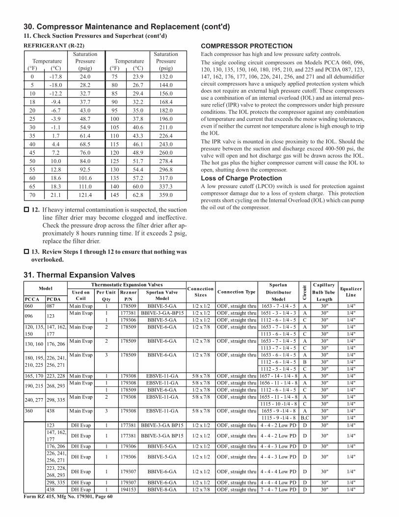
18. Cooling Refrigeration SystemThe refrigerant circuits are fully charged with R22 refrigerant before leav-ing the factory. During the check-test-start procedures in Paragraph 23,page 47, the subcooling and superheat temperature and pressure checkswill verify that the unit is ready for operation.
13. Blower MotorCheck the unit rating plate or motor name plate (See Figure 18, page 25,Item 34 or 35) to verify voltage, HP and type. Use an amp meter to checkmotor amps. Blower motor amps are shown in the Electrical Data Tableon page 29.Amps may be adjusted downward by reducing blower RPM or increasingduct system static pressure.Blower motors over 3HP include a starter. 1/2-3HP motors have internaloverload protection but may be equipped with an optional starter (OptionAN10); check the wiring diagram.
14. Condenser Fan Motors and FansAll PCCA and PCDA systems have 3/4 HP condenser fan motors (Seequantities and amps in the Electrical Data Table above). Condenser fanmotors are open dripproof motors with external sling protection againstwater penetration. The condenser coils, fans, and motors are located ontop of the system; refer to Figure 27.Maintain minimum clearances around the fans as illustrated in Figure 4on page 12. Above the fans should always be unrestricted, open area.
Condenser Fan Arrangements and CyclingSequenceFan arrangements are shown in Figure 28.
Condenser fan cycling control is not required for standard units (lowambient standard is 65°F/18°C).
Figure 27 - Top viewshowing condenser fans
However, a Model PCCA 240, 277, or 360 or a Model PCDA 298,335, or 438 equipped with a hot gas bypass option does include firststage condenser fan cycling control; condenser fan # 2 is disabledbelow 75°F/23°C.
Refer to the graphs in Figures 33A-33E for operating pressures.Graphs in Figures 33A, 33B, and 33C are for one compressor only;graphs in Figures 33D and 33E are for one set of two tandem com-pressors. Calculate the appropriate pressure for a system from thequantity and type of compressors per size as listed in Figure 32.
Form RZ 415, Mfg No. 179301, Page 33
Models PCCA 060 and PCDA 087 have one cooling refrigerant cir-cuit. Models PCCA 096, 120, 130, 135, 150, and 160 and PCDA 123,147, 162, 176, 177, and 206 have two cooling refrigerant circuits. Mod-els PCCA 180, 195, 210, and 225 and PCDA 226, 241, 256, and 271have three cooling refrigerant circuits. Models PCCA 165 and 170 andPCDA 223 and 228 have one cooling refrigerant circuit with tandemcompressors. Models PCCA 190 and 215 and PCDA 268 and 293 havetwo cooling refrigerant circuits, one with a single compressor and onewith tandem compressors. Models PCCA 240 and 277 and PCDA 298and 335 have two cooling refrigerant circuits, each with tandem com-pressors. Models PCCA 360 and PCDA 438 has three cooling refriger-ant circuits, each with tandem compressors.
In addition to the compressors and coils, all refrigeration circuits in-clude thermal expansion valves, filter driers, an auto reset external lowpressure cutout, and service ports. Refrigerant circuits with single com-pressors (PCCA 060, 096, 130, 160, 120, 135, 170, 180, 195, 210, 225and PCDA 087, 123, 176, 206, 147, 162, 177, 226, 241, 256, 271)have automatic internal high pressure relief. Refrigerant circuits withtandem compressors (PCCA 165, 170, 244, 277, 360 and PCDA 223,228, 298, 335, 438) have external, manual reset high pressure cutouts(cutout activates at 400 psi ±10; will allow manual reset at 250 psi±18). Models PCCA 190 and 215 and PCDA 268 and 293 have anexternal manual reset relief in both the single compressor circuit andthe tandem compressor circuit. For location of controls, see Figure18, page 25, Item 47.
Optional Hot Gas BypassSee hot gas bypass circuit in Figure 29. The hot gas bypass optionprovides expanded compressor modulation at low outside air tempera-tures. It is factory set; however, the factory adjustment should be checkedat startup. To check the valve operation and/or make field adjustments,it is necessary to simulate a light load condition.Check Bypass Valve SettingConnect a pressure gauge to the suction line and block the entering airto the evaporator coil. Suction pressure will drop and the hot gas by-pass valve should begin to open at approximately 75 psig. The valvehas a range of 6 psig and will be fully open at 69 psig. When the valvebegins to open, it will be warm to the touch. To adjust the pressure,remove the cap and turn the adjusting stem clockwise to increase the
Figure 29 - Sampleof one RefrigerantCircuit (with anOptional Hot GasBypass Circuit)
Figure 30 -OptionalHot GasBypassValve
Hot Gas Bypass Valve FactorySetting (psi) Change per Turn
Factory PSIAdjustment Setting per
Range PSI Turn
0/80 75 7.5
setting pressure and counterclockwise to decrease the setting pressure.Make adjustments in small increments. Allow five minutes betweenadjustments for the system to stabilize. When finished, replace the capon the adjustment stem and remove the pressure gauge.
CompressorsAll of the compressors are high effi-ciency hermetic reciprocating type.The primary cooling compressors aremounted to supports on the top of thesystem cabinet. The reheat compres-sor in the dehumidifying circuit of aModel PCDA is located inside the coilsection cabinet.The primary cooling compressors areequipped with crankcase heaters thatmust be energized for at least 24 hoursbefore starting the unit or after a poweroutage of more than 8 hours.Refer to the Electrical Data Table on page 29 for compressor amp loadsand Figures 33A-33E for compressor operating pressures. Dehumidi-fying compressor performance is in Figure 34B. Use the table in Fig-ure 32 to determine the combination of compressors; graphs in Figures33A-E are identified by the capacity of each compressor.
Figure 31 - Compressor
Compressor StagingEach PCCA and PCDA system will leave the factory with the follow-ing compressor staging sequence. NOTE: Not all sizes have all com-pressors; refer to the table in Figure 32 to determine which compres-sors apply to which size models.
COMPRESSOR STAGING
Model PCCA 060 and Model PCDA 087Stage PCCA Compressor PCDA Compressors
1st Stage B D2nd Stage N/A B
Model PCCA 096 and Model PCDA 123Stage PCCA Compressors PCDA Compressors
1st Stage A D2nd Stage C (A is off) A3rd Stage A & C C (A is off)4th Stage N/A A & C
Figure 33A -OperatingHead Pressureof One 3-TonCompressor
180
200
220
240
260
280
300
320
340
360
380
400
50 55 60 65 70 75 80 85 90
Compressor Suction (PSIG)
Liq
uid
Lin
e (
PS
IG)
115oF Ambient (Dry Bulb)
105oF Ambient (Dry Bulb)
95oF Ambient (Dry Bulb)
85oF Ambient (Dry Bulb)
75oF Ambient (Dry Bulb)
�� �� �� �� � � � � ����
���
���
���
���
��
���
���
���
���
��
���
��G�� ��������.��,
�8,:����8��.����8����.��"
���A5��29
('%*���$?��#
)9,
���A5��29
('%*���$?��#
)9,
��A5��29('
%*���$?��#)9
,
�A5��29('%
*���$?��#)9,
�A5��29('%
*���$?��#)9,
Figure 33B - Operating Head Pressure of One 5-TonCompressor
Applies to (Refer to Figure 32)
Applies to (Refer to Figure 32)PCCA Qty Location096 1 APCDA Qty Location123 1 A
PCCA Qty Location060 1 B120 2 A, C130 2 A, C135 1 A180 3 A, B, C190 1 C195 2 A, B210 1 A215 1 C
PCDA Qty Location087 1 B147 2 A, C162 1 A176 2 A, C226 3 A, B, C241 2 A, B256 1 A268 1 C293 1 C
�� �� �� �� � � � � ����
���
���
���
���
��
���
���
���
���
��
���
��G�� ��������.��,
�8,:����8��.����8����.��"
���A5��29(
'%*���$?��#)
9,
���A5��29
('%*���$?��
#)9,
��A5��29('
%*���$?��#)9
,
�A5��29('%
*���$?��#)9,
�A5��29('%
*���$?��#)9,
Figure 33C - Operating Head Pressure of One 6.25-tonCompressorApplies to (Refer to Figure 32)PCCA Qty Location135 1 C
150 2 A, C
160 2 A, C
195 1 C
210 2 B, C
225 3 A, B, C
PCDA Qty Location162 1 C
177 2 A, C
206 2 A, C
241 1 C
256 2 B, C
271 3 A, B, C
�� �� �� �� � � � � ����
���
���
���
���
��
���
���
���
���
��
���
��G�� ��������.��,
�8,:����8��.����8����.��"
���A5��29(
'%*���$?��#)
9,
���A5��29
('%*���$?��#
)9,
��A5��29('
%*���$?��#)9
,
�A5��29(
'%*���$?��#
)9,
�A5��29('
%*���$?��#)9
,
Figure 33D - Operating Head Pressure of One Set of TwoTandem 5-ton Compressors (10-ton)Applies to (Refer to Figure 32)
PCDA Qty Location223 1 C
268 1 A
298 2 A, C
438 3 A, B, C
PCCA Qty Location165 1 C
190 1 A
240 2 A, C
360 3 A, B, C
Form RZ 415, Mfg No. 179301, Page 36
2������ ���������,�#��������
@/F����;:<F��A�
�����������,�#��������
=.F����;@9F��A�
2������)���������������,�#��������
=:F��������6����
����#��� �����#�������
����#��� �����������������
����#��� ��� ��������������
18. Cooling Refrigeration System (cont'd)
Figure 33E - Operating Head Pressure of One Set ofTwo Tandem 5.6 ton Compressors (11.2-ton)
Applies to (Refer to Figure 32)
PCDA Qty Location
228 1 C293 1 A
335 2 A, C
PCCA Qty Location
170 1 C215 1 A
277 2 A, C
Dehumidifying Refrigerant System - Model PCDA onlyThe dehumidifying refrigerant circuit is a closed system that includes the same components as the larger cooling circuits. The system is fullycharged with R22 refrigerant before it leaves the factory. For charging table, see Figure 32, page 34.
Both the condenser coil and the compressor are located inside the coil cabinet downstream of the cooling evaporator coil. In this location, they actto raise the temperature of the airstream (reheat) after it has passed through the dehumidifier evaporator coil.
Model PCDA Dehumidifier Performance - The PCDA dehumidifier refrigeration system can be checked in a stand-alone mode or in conjunctionwith the primary refrigeration system. In general, suction line superheat should be in the 8 to 12°F range, and liquid line subcooling should be in the18 to 25°F range. When compared to conventional refrigeration performance, the dehumidifier suction pressures will tend to be higher anddischarge pressures lower.
The first table (on the left) below shows typical PCDA dehumidifier performance in a stand-alone mode (without primary cooling compressors).The second table (on the right) shows PCDA dehumidifier performance with a nominal 55°F/12°C supply air temperature entering the dehumidifierreheat condenser (primary cooling compressors enabled).
Both tables are developed for nominal airflow rates. Field measurements of pressures should be within 10-12% of listed values.
�� �� �� �� � � � � ����
���
���
���
���
��
���
���
���
���
��
���
��G�� ��������.��,
�8,:����8��.����8����.��"
���A5��29
('%*���$?��#)9,
���A5��29
('%*���$?��#
)9,
��A5��29('
%*���$?��#)9
,
�A5��29(
'%*���$?��#
)9,
�A5��29(
'%*���$?��#
)9,
Typical Stand-Alone Dehumidifier Performance(subtract 18 psig for liquid line pressure)
Applies to all sizes ofModel PCDA - Thedehumidifyingcompressor is locatedin the coil cabinet
16. Blowers, Belts, and DrivesCheck belt tension. Proper belt tension and alignment is important tothe long life of the belt and blower motor. A loose belt will cause wearand slippage. Too much tension will cause excessive motor and blowerbearing wear. Adjust the belt tension by turning the adjusting screw onthe motor base until the belt can be depressed 3/4" (19mm). See Figure35. After correct tension is achieved, re-tighten the locknut on the ad-justment screw. Be sure that the belt is aligned in the pulleys.
Adjusting Blower SpeedThe blower speed may be adjusted to achieve the desired outlet tem-perature. If the system includes a furnace, any adjustment must be withinthe temperature rise and the static pressure limits shown on the furnacerating plate. Motors are factory set between maximum and minimumblower speeds.
If the duct resistance is low, the blower may deliver too high an airvolume. If the resistance is very low, the blower may deliver excess airto overload the motor, causing the overload protector to cycle the mo-tor. Reducing the blower speed will correct these conditions. If duct-work is added to an installation, it may be necessary to increase theblower speed. Decreasing blower speed will increase outlet tempera-ture (heating) or decrease outlet temperature (cooling); increasingblower speed will decrease outlet temperature (heating) or increaseoutlet temperature (cooling).
At final adjustment, amperes should not exceed motor nameplateamp rating. If heating is included, the temperature rise must bewithin the range specified on the furnace rating plate.
The belt drive on these units is equipped with an adjustable pulleywhich permits adjustment of the blower speed. Follow these instruc-tions to adjust the blower speed.
1. Turn off the gas (if equipped with a furnace) and the electric power.
2. Loosen belt tension and remove the belt.
3. Loosen the set screw on the side of the pulley away from the motor.
/;14��-0##!Figure 35 - CheckBelt Tension
4. To increase the blower speed, turn the adjustable half of the pulleyinward. To decrease the blower speed, turn the adjustable half ofthe pulley outward. One turn of the pulley will change the speed 8-10%.
5. Tighten the set screw on the flat portion of the pulley shaft.
6. Replace the belt and adjust the belt tension. Adjust tension by turn-ing the adjusting screw on the motor base until the belt can be de-pressed 3/4". (See Figure 35.) Re-tighten the lock nut on the adjust-ing screw. Be sure that the belts are aligned in the pulley groovesproperly and are not angled from pulley to pulley.
7. Turn on the gas (if equipped with a furnace) and the electric.
8. Check the motor amps with an amp meter. The maximum motoramp rating on the motor nameplate must not be exceeded.
When service is complete, check for proper operation.
Blower RotationEach blower housing is marked for proper rotation. When viewed fromthe drive side, that rotation is clockwise. If actual rotation is not cor-rect, interchange the two wires on the 3-phase supply connections atthe terminal block. Do not change load side wiring.
* Refer to the airflow chart on the top of page 38 for CFM limits by model. Consult the factory for non-catalogued airflow rates.
** Option AU20 is the evaporator coil recommended for use in Model PCCA 120, 135, 150, 180, 195, 210, and 225. But, Option AU21 isavailable; check the order and/or the Parts Replacement Tag to verify the type of coil on the unit.
Option AU21 is the evaporator coil recommended for use in Model PCDA 147, 162, 177, 226, 241, 256, and 271. But, Option AU20 isavailable; check the order and/or the Parts Replacement Tag to verify the type of coil on the unit.
*** Airflow range requires bypass air, Option AQB2.
Form RZ 415, Mfg No. 179301, Page 40
OPTIONAL EQUIPMENTThe list below indicates where to find installation information for optional equipment. Some options are located in this Optional EquipmentSection. Others are located throughout the system manual. A separate manual is provide for optional gas-fired furnace installation.
18. Optional Cooling Coil Bypass (Applies only to Models PCCA 120, 135, 150, 240, and 277)Description/ApplicationIf the application requires a higher airflow rate at a given cooling capacity (i.e. a higher Cfm/ton) and the system was ordered with Option AQB2,the unit is equipped with an adjustable air bypass plate. The plate is located above the cooling coil and is adjusted at the factory to a fixed openposition. The cooling coil bypass air prevents water blowoff from the cooling coil and reduces coil pressure drop while providing full airflow for thespace and for the unit furnaces (if equipped with a heat section).
A typical application for the bypass duct is in dry, relatively mild climates and/or applications where humidity control is not of great concern.
Figure 36 - Inside of Coil Cabinet with OptionalCooling Coil Bypass, Option AQB2The opening is factory set to specifications supplied withthe order. If pressure testing indicates that field adjustmentis required, move the upper plate to increase or decreasethe size of the opening.
SmallCoilBypassOpening
LargerCoilBypassOpening
UpperPlate
LowerPlate
LowerPlate
UpperPlate
Option (alphabetically listed) ........................................................................................................ Where to LookBarometric Relief Hood, Option ASB1 ................................................................................ Paragraph 10, page 20Controls, Cooling and Cooling/Dehumidifying ............................................................ Paragraph 12, pages 26-29Dampers (Inlet or Discharge), Options AQ & AR ........................................................ Paragraph 19, pages 41-42Evaporative Cooling Module, Option AS 3, 4, 5, or 8 (PCCB only) ............................ Paragraph 21, pages 43-46Gas Furnace, Models __-000 (includes all gas furnace options) ................................................ Form 415/416-GFHot Water Heat Coil, Models __-001, Option LW ............................................................... Paragraph 20, page 42Roof Curb, Opt CJ ........................................................................................................... Paragraph 8, pages 14-16Screened Inlet Air Hood, Opt AS2 ................................................................................ Paragraph 10, pages 19-20Screened Inlet Air Hood, Opt AS16 .............................................................................. Paragraph 10, pagse 20-21Steam Heat Coil, Models __-001, Option LS ...................................................................... Paragraph 20, page 43Through-the-Base Electrical Supply Entrance, Opt AVC1 .................................................. Paragraph 12, page 22
-<4�1:=##!
<4�9./##!
����
���
�����
����
�
-<4�1:=##!
<4�9./##!
��������
����� ��������������
�����
Figure 37 - Where to DrillPressure Tap Holes
During equipment startup, it is important to check the discharge airsetpoint to ensure it meets specifications (typically the discharge airsetpoint of a system with an optional bypass will be adjusted higherthan a non-bypass application). If standard factory discharge controlsettings are not adjusted, actual cooling coil temperatures may be lowerthan nominal to deliver the required supply air temperature.
Check bypass plate adjustment during test and balance to ensure properair flow quantities.
Airflow and Size of Bypass OpeningFor best results, it is recommended that the system airflow rate and coilair pressure drop be determined with the cooling coil in a “wet” condi-tion and compressors activated with supply air temperatures of a nomi-nal 55°F/12°C.
Two static pressure taps must be field installed to measure the coilpressure drop. Measure pressure drop with the filters removed. Com-pare pressure drop with the table on page 41. If pressure drop is belowthe minimum, the upper bypass plate can be adjusted to provide lessopening and increase coil pressure drop. If pressure drop is above themaximum, the upper plate can be adjusted to provide a larger openingand decrease coil pressure drop.
Instructions for measuring pressure drop:
1) Drill two small holes for measuring pressure. See Figure 37.
Airflow
2) Remove Filters - Remove the filter section door. On each level(upper and lower), the filters fit into a sliding frame. To remove theupper set of filters, slide the upper frame out. Remove filters; slideframe back. To remove the lower set of filters, slide the lower frameout. Remove filters; slide frame back. Close the filter section door.
Form RZ 415, Mfg No. 179301, Page 41
4) If pressure drop is below the minimum, adjust bypass plates to in-crease the pressure drop. If pressure drop is above the maximum,adjust bypass plates to decrease the pressure drop.
If adjustment is necessary, use the table below to estimate the plateposition. Re-measure to verify pressure drop. NOTE: The measure-ments below are based on minimum wet coil pressure drop with astandard coil. If measuring pressure through a dry coil or if an op-tional high capacity coil (Option AU21) is installed, adjust plategradually until appropriate pressure drop is reached.
Bypass Air Quantities versus Opening SizeBypass Bypass Opening Height - Model PCCA
Air Qty 120, 135, 150 240, 277
(CFM) inches mm inches mm
1700 N/A N/A 5 127
1400 N/A N/A 4 102
1100 3.3 84 3.5 89
900 2.7 69 2.9 74
700 2.1 53 2.2 56
500 1.5 38 1.7 43
300 1 25 1.2 30
200 0.7 18 0.8 20
5) When bypass is adjusted within correct pressure, remove pressuregauge. Replace filters.
3) Insert pressure sensing tubes. Operate system. Measure pressuredrop through coil. Compare pressure drop range to table below.
NOTE: The pressure drops in the table are based on an applicationwith 55°F/12°C leaving coil air temperature at 0-2000 ft (0-610 M)elevation. If elevation is above 2000 ft (610 M), apply altitude cor-rection factor.
Acceptable Coil Pressure Drop Range (inches w.c.)Model PCCA 120, 135, 150 240, 277
19. Optional Dampers and ControlsThe system may be equipped with an outside air damper, outside and return air dampers, a discharge damper, or both inlet and discharge dampers.Check the wiring diagram shipped with the unit to verify electric damper control; dampers with electric controls will be designated as an AQ or ARoption.
Discharge Air Damper (Option AQ8)A discharge air damper applies only to vertical discharge systems. The two-position discharge damper motor is located inside the downturn plenumsection and is directly connected to the damper. The discharge damper closes when the unit is not operating.
Outside Air Damper and Return Air Damper OptionsOption Code
Description ApplicationSensor
LocationControl
Locations
AR27
Zone Pressurization Control, Fully M odulating Motorized Outside and Return Air Dampers with Minimum Outside Air Damper Position and
Pressure Null Switch (Outside air is horizontal opening; return air is bottom opening)
AR57 Same as AR27 but both outside air and return air openings are horizontal.
AR23Zone Pressurization Control, Fully M odulating Motorized Outside and Return Air Dampers and Pressure Null Switch (Outside air is horizontal
opening; return air is bottom opening)
AR56 Same as AR23 but both outside air and return air openings are horizontal.
AR18100% Outside Air and 100% Return Air Dampers with Modulating
Motor (0-100% Outside Air with Remote Position Adjustment) (Outside air is horizontal opening; return air is bottom opening)
AR55 Same as AR18 but both outside air and return air openings are horizontal.
AR17100% Outside Air and 100% Return Air with Dampers with 2- Position Motor (Outside air is horizontal opening; return air is bottom opening)
AR54 Same as AR17 but both outside air and return air openings are horizontal.
AR8 100% Motorized Outside Air Damper - 2 Position MotorMotorized outside air damper is opened 100% during unit operation. If unit is disabled, outside air damper is closed by spring return.
N/AMixed Air
Inlet
AR11100% Outside and Bottom Return Air Opening, both with Dampers (Manual Adjustment) Outside air is horizontal opening; return air is
bottom opening)
AR53 Same as AR11 but both outside air and return air openings are horizontal.
Field Installed in Space
Modulates return and outside air damper positions to maintain zone pressure by regulating return and outside air quantities (constant volume air flow). On shutdown, the outside air damper closes.
SpaceField
Installed in Space
Modulates return and outside air damper positions to maintain zone pressure (modulates from minimum outside air damper position to 100%) by regulating return and outside air quantities (constant volume air flow). On shutdown, the outside air damper closes.
Space
Field Installed in Space or Mixed Air Inlet
Provides manual adjustment of return and outside air dampers
Mixed Air Inlet
N/AMixed Air
Inlet
Motorized outside air dampers are driven 100% open and return air dampers are driven 100% closed when unit is enabled. If unit is disabled, outside air damper is closed (return air damper opened) by spring return. Field installed time clocks may provide for occupied and unoccupied control sequences.
N/A
Modulating damper motor provides for mixture of return and outside air as controlled by a manually set potentiometer. On shutdown, the outside air damper closes.
N/A
Form RZ 415, Mfg No. 179301, Page 42
20. Optional Heat Coil ModuleThe heat coil module is available
• with a factory-installed hot water coil (Option LH),
• with a factory-installed steam coil (Option LS),
• or designed for installation of a field supplied hot water orsteam coil.
Boiler, accessories, controls and lines are field supplied.
Hot Water Coil, Option LHIf factory equipped with a hot water coil, run the return andsupply connections through the base (See Figure 39). Supplyand return connections are 2" MPT. Return connection is at thetop of the coil; supply connection is at the bottom. Coil has1/2" FPT vent and drain with plugs.
Use swing joints or flexible fittings in piping connections lo-cated adjacent to the heating coil.
A hot water coil may be used for a coil run-around loop recov-ery system.
,���C���
7��6���� ��
2�������0 ����
� ��� �&0��3���8���#��������7���,�����%�7� ���
��)�2�A
������������%����# �������9&-;94������'
������������������'
Figure 39 - Hot Water Heat Coil Connections
��������+
�����G������
���������"����
"��������,���
2��
���
�
"���������G�������
���������
���������2�����������������#
2����##������
������G���#���
����� ������������
����������������������������������������
Damper LinkageDamper linkage provides limited air balance of return and outside airquantities. Return duct and outside air hood pressure drop differentialsmay require field-installed balancing dampers.
Pressure Null Switch in Damper Options AR23 andAR27The pressure null switch used in Option AR23 and AR27 is a Dwyer#1640-0 with a range of .01-.20" w.c. It is shipped separately for fieldinstallation. Refer to the following paragraphs and the manufacturer'sinstallation instructions included with the switch.
Description and Application - The pressure null switch is a diaphragmoperated differential pressure switch used in makeup air applicationsto control building pressure. It maintains a selected positive or nega-tive pressure setpoint by changing the amount of outside air being in-troduced to the building through the modulating outside air dampers.As more pressure is required in the building, the pressure null switchactivates the damper motor driving the outside air damper towards thefull open position and the recirculated air damper towardsthe closed position. Conversely, as less pressure is required,the switch drives the dampers in the opposite direction.
Installation Instructions for Pressure Null Switch1. Select an indoor location free from excessive vibration
where oil or water will not drip onto the switch and whereambient temperature will be within a range of -30°F (dryair) to 110°F.
2. Mount the switch with the diaphragm in a verticalplane. The switch is position sensitive and is calibratedto operate properly when the diaphragm is vertical. Mountswitch securely.
3. Connect the pressure taps on the top of the switch tosources of air pressure differential. Metal tubing with 1/4" O.D. is recommended, but any tubing system whichwill not unduly restrict the air flow may be used. To main-tain a positive building pressure, vent the low pressuretap to the outdoors and allow the high pressure tap tomonitor building pressure. To maintain a negative build-ing pressure, reverse the functions of the high and lowpressure taps. In either case, be sure that the outdoor ventis protected from the wind and screened from insects.
Figure 38 - Pressure Null Switch(shipped separately for use with
Options AR23 and AR27)
4. Adjustment of the Switch - The "HIGH" actuation point of thenull switch is indicated on a calibrated scale secured to the trans-parent range screw enclosure. Building pressure is set by turningthe adjustment screw. The "Low" actuation point is set by adjustingthe span of the null by turning the span adjustment screw. The spanrange is .01 to .03" w.c.
IMPORTANT: To eliminate shipping damage to the switch contacts,the manufacturer reduced the span adjustment to zero before shipping.The span should be adjusted prior to using the switch. (If the switchhas been installed, disconnect the vent tube so that the null switch is ina neutral position.) Remove the electrical box cover and while observ-ing the contacts, turn the span adjustment screw slowly in a clockwisedirection. Continue turning the adjustment screw until you are able tosee gaps between the common and both the low and high contacts. Aminimum gap provides the greatest sensitivity. The wider the gap thelower the sensitivity.
5. See the wiring diagram included with the furnace to make electricalconnections.
19. Optional Dampers and Controls (cont'd)Outside Air Damper and Return Air Damper Options (cont'd)
Form RZ 415, Mfg No. 179301, Page 43
Steam Coil, Option LSIf factory equipped with a steam coil, the re-turn and supply connections are through thecabinet side (See Figure 40). Coil connectionsare 2" MPT. Service access to the coil is fromthe side opposite the connections.
��)�2�A
((&����� �'�����
�1&����� ��*����+&�(���
��1'���
��������� ��94��",�����6
����)���������������
Figure 40 -Steam CoilConnections
21. Optional Evaporative Cooling Module - Model PCCA only
Figure 41 - OptionalEvaporative CoolingModule is factory-installedon the system cabinet
To provide comfort coolingunder dry ambient conditions,the optional evaporative cool-ing module will operate atlower cost than the cooling coilcircuit. Direct evaporative coolingworks solely by exchanging latentfor sensible energy in an airstream.This evaporative cooling moduleuses wetted rigid cellulose or rigidglass fiber media to retain water inorder to allow time for evapora-tion.The optional evaporative cool-ing module is equipped withhigh efficiency pad media of ei-ther 6" or 12" rigid cellulose
(Option AS3 or AS4) or 6" or 12" rigid glass fiber (Option AS5 orAS8). Six-inch media provides 68% efficiency; 12" media provides90% efficiency. Efficiency values are stated at maximum allowable CFMwithout the addition of a moisture elimination pad with an inlet drybulb temperature of 95°F and inlet wet bulb temperature of 65°F. Theevaporative cooling efficiency is a function of the difference betweeninlet dry and wet bulb temperatures and face velocity. The stated cool-ing efficiency will rise with decrease of CFM and increase of the dif-ference between inlet dry bulb and wet bulb air temperatures. Moistureelimination pads (Option ASA1) may be used on all units but are re-quired for airflows above 600 FPM.
The standard water controls for the evaporative cooling module in-clude the float valve, the float switch, and pump assembly illustrated inthe following paragraphs. If the cooling module has an optionalAquaSaver® metering water system, it will not have these controls butwill have a solenoid valve with a timer assembly for controlling waterflow.
CAUTION: Water reservoir must be drained andpump motor turned off when outsidetemperature falls below 32°F/0°C. Pump mustnever be operated without water in the reservoir.See Hazard Levels, page 2.
Installation Instructions - Evaporative CoolingModuleThe evaporative cooling module is completely factory assembled, in-stalled and wired. No additional roof mounting is necessary. Followthese instructions to field connect the water supply and make neces-sary checks and adjustments before operating the cooling module.
SimulatesSide Panel
Use 1/4"Tubing forFresh WaterSupply
Compression Nutand Tubing Ferrule(Inside
Cabinet)
FloatValveRod
Figure 42 -ConnectFresh WaterSupply toInlet of FloatValve
Supply and Drain Water ConnectionsFloat Valve (Figure 42) - In a module with pump and float controls, afloat valve maintains the appropriate water level in the reservoir.
Use field supplied 1/4" diameter tubing with a compression nut andtubing ferrule to connect the fresh water supply to the inlet of the floatvalve. Place nut and ferrule over tubing and insert tubing into the floatvalve stem. Tighten nut securely.
AquaSaver® Timed Metering Control System - If the cooling mod-ule is equipped with an optional timed metering system, connect a 1/2"water line to the fitting on the side of the cooling module.Due to various water pressures and installation conditions, the watersupply line may bang abruptly when the solenoid valve in the AquaSaversystem closes. This banging can be minimized by installing an op-tional water hammer arrestor in the supply line. When installing anarrestor, select an indoor (above 32°F/0°C) location, either horizontalor vertical, in line with and as close to the solenoid valve as possible.Follow the manufacturer's instructions to install and maintain the wa-ter hammer arrestor.
All Cooling Modules - A manual water shutoff valve should be in-stalled upstream of the cooling module inlet, at a convenient non-freez-ing location, to allow the water supply to be turned on and off. If nec-essary, install a bleed line between the manual valve and the coolingmodule to allow drainage of the line between the shutoff valve and thecooling module.
All cooling modules are equipped with overflow and drain fittings.The fittings are in the cabinet bottom and come complete with a locknuts and sealing gaskets. Check these fittings for tightness before in-stalling the overflow and drain piping. The drain and overflow fittingswill accommodate a 3/4" garden hose thread and are tapped with a 1/2"female pipe thread for iron pipe.An optional automatic fill and drain kit (Option CT) is available thatwill automatically release supply water to the cooling module when acall for cooling is made and drain all water from the reservoir when the
Form RZ 415, Mfg No. 179301, Page 44
Instructions for Installing Optional Fill & DrainKitNOTE: Follow instructions included in the valve packagesfor attaching valves to the water line only. The remainder ofthe installation instructions with the valves does not apply tothis type of application.Water Line Connections (See Figure 44):Supply (3-Way Valve) Connections - Connect the water sup-ply line to "B" (normally closed). Connect the water drainline to "A" (normally open). Connect the middle outlet tosupply the water to the cooling module reservoir.Drain (2-Way Valve) Connections - Connect the drain pipefrom the reservoir to the valve inlet. Connect the outlet sideinto the drain lines from the cooling reservoir and the supplyvalve.Electrical Connections (requires black and white 14-gaugewire) - Refer to Wiring Diagram provided with the fur-nace:
WARNING: Disconnect the power. Riskof electrical shock.
1. Refer to the wiring diagram for terminal con-nections. (NOTE: If kit is not ordered withthe system, connections will not be shownon the diagram. Terminal connections arespecific to each system. Contact the factoryfor terminal connections. Be prepared to pro-vide all model information.)
2. Run field supplied black wire from the elec-trical compartment (terminal on the wiringdiagram) of the evaporative cooling moduleand connect to the black wire on both the 3-way and the 2-way valve.
3. Run field supplied white wire from the elec-trical compartment (terminal on the wiringdiagram) of the evaporative cooling moduleand connect to the white wire on both the 3-way and the 2-way valve.
Figure 44 - Water Connections including Optional Drain and FillKit
cooling switch is deactivated or a cooling thermostat is satisfied.See Figure 44. If installing an optional fill and drain kit, follow theinstructions with Figure 44. Consult wiring diagram for electricalconnections. (NOTE: The Option CT5 kit for an evaporative cool-ing module with an AquaSaver® timed water control system is forfreeze protection. It includes one valve, a temperature controller,and required relays.)
Bleed Line Connection (Does not apply to module with optionaltimed metering system.)- Shipped in the evapo-rative cooling modulebottom pan, find a 1/4"I.D. x 1/2" N.P.T. nylonbleed line fitting (hosebarb). Thread the fittinginto the female adapterlocated opposite thepump/inlet side of thewater distribution line.The hose barb will pro-trude from the side ofthe cabinet (See Figure
43). Attach a 1/4" I.D. hose to the barb and run the hose to thenearest drain.Discharging a quantity of water by "bleed off" will limit the con-centration of undesirable minerals in the water being circulatedthrough the cooling module. Minerals buildup because evapora-tion only releases "pure water vapor" causing the concentrationof contaminants in the water to increase as the evaporation pro-cess continues to occur. The minerals accumulate on the media,in the water lines, on the pump, and in the reservoir. Adequatebleed off is important to maintaining an efficiently operatingevaporative cooling system.
Installthe hosebarbandattachbleedline.
21. Optional Evaporative Cooling Module - Model PCCA only (cont'd)
Supply and Drain Water Connections (cont'd)
Figure 43 - Bleed LineConnection
Filling & Adjusting Reservoir Water LevelFloat and Pump Control System - Turn on the water supply. Check forgood flow.When the float valve (Figure 42) shuts off the water supply, measure thewater depth. The depth of the water should be approximately 3". It may benecessary to adjust the float valve to obtain the proper water level or tofree the float valve from obstructions. To adjust the float valve, simplybend the rod upward to raise the water level or downward to decrease thewater level.
Adjusting Water Flow Over PadsProper water flow over the evaporative cooling media is critical to extendthe life and maintain the efficiency of the pads. Follow the instructions toadjust water flow.
CAUTION: Do not flood the media pads with extremequantities of water for long periods as this will causepremature breakdown of the media. An even flow fromtop to bottom of the media with the least amount ofwater is all that is required to assure maximumefficiency and media life span. More water does notprovide more evaporation or more cooling.
WARNING: Adjust ball valve only when the poweris disconnected from the system. Failure to do socan cause electrical shock, personal injury or death.
Float and Pump Control System - Using the ball valve, located in themiddle of the length of hose running from the pump to the distribution lineinlet (Figure 45), adjust the valve handle to allow the flow to completelydampen the media pads from top to bottom.Operate the unit watching the water flow. After 18 minutes with the blowerin operation, the water should have completely dampened the pads butshould not be flowing off the entering side of the media. If water is flow-
Form RZ 415, Mfg No. 179301, Page 45
�
Figure 46A - Adjust Water Flow with the Ball Valve inFigure 45 Pad A = Water rise from
Height PVC Sprinkler Pipe24" 1/8" to 1/2"48" 1/4" to 1/2"
the media becomes too clogged with mineral deposits and dirt that itcannot be cleaned, the pads should be replaced. The average pad lifeexpectancy is approximately three cooling seasons.
Select the correct replacement part numbers and order replacement me-dia pads from your distributor. Follow the instructions that follow andremove and replace pads as shown in Figures 47A and 47B.
Figure 45 - Disconnect thepower and use the ballvalve to adjust water flow
BallValve
ing off the entering side of the me-dia, turn the system off, disconnectthe power, and reduce the enteringwater flow.
AquaSaver® Timed MeteringControl System - NOTE: Waterflow and pad wetting time shouldbe adjusted at maximum air flowand wet bulb depression to assurecomplete wetting of the media at the
extreme operating conditions.In addition to adjusting water flow, the timing of the water on/off cyclecan be adjusted. Adjustments are correct when l) the water rises fromthe holes in the sprinkler pipe (See Figure 46A) consistently along theentire pipe length, 2) the media pads wet evenly after a few "ON" cycles(no dry spots or dry streaks), and 3) a slight amount of excess watercollects at the drain at the completion of the "ON" cycle.1) AquaSaver® Water Flow Adjustment - Using the ball valve illus-trated in Figure 45, adjust the water flow depending on the pad height.See Figure 46A.
2) AquaSaver® Timer Adjustment - At any given temperature, themedia pads should completely wet from top to bottom during the ONcycle. If the ON time is less than 45 seconds or greater than 90 secondsat 80°F, adjust the timer. Remove the junction box cover to access thetimer adjustment screw (See Figure 46B).
Through the use of a bimetallic strip, the timer is temperature sensitiveand automatically increases the ON time approximately one second foreach 1°F rise above the 80°F factory setting. The ON time will equalthe setting for 80°F plus a second for each degree above 80°F.Let the unit cycle a few times to verify that the water flow is correct andthe soaker hose is operating properly to wet the media pads completelyfrom top to bottom during the ON cycle.
All Modules - Check the reservoir for any water leaks. The reservoirwas water tested, but if any small leaks are present, drain the reservoirand apply a waterproof silicone sealer around corners and welds.
Evaporative Cooling Module MaintenanceReference: Troubleshooting Guide for Evaporative Cooling Moduleis part of Paragraph 32.
WARNING: Disconnect all power to the unitbefore doing any maintenance. Failure to do so cancause electrical shock, personal injury or death.
Media - Over time, excessive amounts of mineral deposits may beginto build up on the media. Annually, scale and dirt should be washed offthe entering surface of the media. Remove the pad retainers and screen(See Steps 1-3 and 6-8 of Media Replacement Instructions). Clean themedia using a garden hose, mild soap, and a soft bristled brush. When
Figure 46B - Junction Box with AquaSaver® Controls
TimerAdjustmentScrew
— To increase the ON time, turn theadjustment screw clockwise; onecomplete turn will increase ONcycle by 12 to 14 seconds.
— To decrease the ON time, turn theadjustment screw counterclock-wise; one complete turn willdecrease ON cycle by 12 to 14seconds.
"��
����
"��)�������
���
Figure 47A - Removaland Replacement ofEvaporative CoolingModule Media
Instructions for Replacing Evaporative Cooling Media1. Remove the three sheetmetal screws that hold the top pad retainer.
Release the top pad retainer from the cooling module.2. Remove the three screws that hold the bottom pad retainer. Release
the bottom pad retainer from the cooling module.3. Disengage the inlet screen from media pads and remove.4. Slide all media pads horizontally away from the cooling module
until clear of bottom reservoir pan. Dispose of properly.5. Slide media pads over both support rails until back stop is encoun-
tered. Media must be placed as shown in Figure 47B.6. Center screen on the incoming air side of the media.7. Replace the bottom pad retainer by securing the retainer between
the pad and the reservoir pan. Fasten with the three sheetmetal screwsremoved in Step 2.
1:F
��� ���������
���������� ���
Figure 47B - Media mustbe installed with 45°
angle sloping downwardtoward the incoming
outside air.
IMPORTANT: The media is made up of two different sheets ofcooling material. Each sheet has its own unique angle. When re-placing the cooling media, BE CERTAIN that the 45° angle slopesdownward toward the incoming outside air. If the media is not in-stalled properly, water blowoff from the media pads will occur.
Media Pad Replacement Part No. (each)
Sizes Qty Cellulose Fiber Glass Fiber
(inches) 6" 12" 6" 12"
24 x 12 3 105985 106021 106037 106029
24 x 1-3/8 1 105988 106024 106040 106032
24 x 12 4 105985 106021 106037 106029
24 x 2-7/8 1 105990 106026 106042 106034
PCCA
060, 096, 120, 135, 150, 130, 160, 180,
195, 210, 225
165, 170, 190, 215, 240, 277, 360
Form RZ 415, Mfg No. 179301, Page 46
Figure 48 - Remove Junction Box, Pump and FloatSwitch as an Assembly
3. Upstream of the ball valve, disconnect the water feed line hose.4. Unscrew the four screws holding the junction box to the cooling
module. Remove the junction box-pump-float switch assembly.5. Dislodge the inlet basket screen from the pump and clean any
buildup of debris and dirt. Carefully remove the base cover platefrom the bottom of the pump. Using a mild soap solution, wash alldeposits from the inside of the pump and remove all debris fromthe impeller.
6. Reassemble the pump. Replace the parts in exact reverse order,being careful that everything is returned to its proper position.
Pump
Junction Box (Note: Only208V unit will have atransformer in the junction box.)
Float Switch
PumpMotor
Carefully remove basket and snap-on cover plate to clean pump
22. Energy Recovery Preconditioner for Makeup Air, Model ERSA
21. Optional Evaporative Cooling Module - Model PCCA only (cont'd)Instructions for Replacing Media (cont'd)8. Replace the top pad retainer by securing the retainer between the
pad and top of the cooling module. Fasten with the three sheetmetalscrews removed in Step 1.
Water Feed and Distribution Line - Annually, the water supply lineand the water distribution line should be flushed of debris and con-taminants.1. Remove the media pads. (Follow media replacement instructions
above.)2. Remove the water feed line from the downstream side of the ball
valve. Unscrew the water bleed line barbed hose fitting.3. Force a fresh water supply through the water inlet hose and thor-
oughly flush the distribution line.4. Reassemble being careful to install media with air flow direction as
shown in Figure 47B.Water Pump and Inlet Basket Screen (Does not apply to modulewith optional timed metering system.) - Annually, the pump and inletbasket screen should be removed, disassembled, and cleaned. Followthe instructions.
WARNING: Do not expose pump motor or any partof the electrical box to water. Evaporative coolingpump is NOT submersible.Pump Removal and Cleaning Instructions1. Disconnect the power supply to the unit.2. Remove the service panel and the junction box door. Inside the
junction box, disconnect the two line voltage power supply wires.
Figure 49 - Dimensions (inches and mm) andConfiguration of a Model PCCA or PCDA with a
Model ERSA Preconditioner Energy RecoveryWheel for Makeup Air
If a Reznor® Model ERSA Preconditioner Heat Recovery Wheel is being installed with a Model PCCA or PCDA, follow the instructions inInstallation Form 480 (shipped with Model ERSA). Refer to Figure 49 for connection and overall dimension information. Top of field supplied ductconnection must be symmetrical with both openings. Recommended ductwork length is 50" (1270mm). Ductwork connection must be sloped andtapered as illustrated.
Form RZ 415, Mfg No. 179301, Page 47
CHECK-TEST-STARTUP
23A. Prior to Startup - should be done 24hours prior to actual startup
Assumptions: All connections are made; actual startup is immi-nent. Site is clean; all excess supplies, scraps, and debris havebeen removed. Weatherhood (or factory-installed evaporativecooling module) is installed. Clean filters are in place. Doorsare removed for checks.
WARNING: To prevent injury or death due toelectrocution or contact with moving parts, lockdisconnect switch open when doing checks priorto startup. See Hazard Levels, page 2.
All Systems:Check clearances. All clearances must be as illustrated in Paragraph7.
Be certain the electrical supply matches voltage rating of theunit. (Refer to the rating plate.)
Check the wiring for loose connections or damaged wire.Tighten connections. Replace damaged wiring. (See Para-graph 12 for replacement wiring requirements.)
Check all field wiring against the wiring diagram. Be sure allfield-installed controls are in place. Be sure that wire gaugesare as required for the electrical load.
Be certain that the electrical entrances are sealed against theweather.
Check that fuses or circuit breakers are in place and sizedcorrectly.
Be certain optional manual reset controls (firestat and highgas pressure switch) are reset.
If any changes are required to factory settings, be sure theyhave been made. See pages 50-51 for list of factory settings.
Check blower pulley and motor pulley to be sure they aresecure to the shafts. Check blower and pulleys for free move-ment. Check belt tension and alignment. See Paragraph 16.
Check free rotation of condenser fans. See Paragraph 14.
Remove compressor tiedowns and all other shipping supportsand restraints.
Be sure that condensate drains are properly trapped and open.See Paragraph 9.
If there is a gas furnace (Refer to Form RZ-NA 415/416-GF):
Check gas piping for leaks and proper gas line pressure. SeeForm RZ-NA 415/416-GF, Paragraph 7. Bleed gas lines oftrapped air.a) Turn manual shutoff valve to off position.b) Turn gas supply on.c) Observe gas meter for movement, ord) Attach pressure gauge readable to 0.1" w.c. and after turn-
ing gas on for ten seconds, turn gas supply off. No changein pressure should occur over a three-minute period.
e) If either c) or d) above indicate a leak, locate leak bybrushing a soapy solution on all fittings. Bubbles willappear at the leak. Repair and repeat tests.
Check to make sure that the combustion air inlet and fluedischarge openings are free of obstructions.
If equipped with gas control Option AG41 or AG42, set theheat stage controllers. See Form RZ-NA 415/416-GF, Para-graph 13C(c).
All Systems:When all checks are completed satisfactorily, close and se-cure all doors.
If actual startup is scheduled in 24 hours, unlock the discon-nect switch and turn on the electric. Allow the compressorsto warm up for at least 24 hours prior to startup.
23B. Startup (ambient temperature above68°F/20°C; if below 68°F/20°C, seeParagraph 23D)
Assumptions: All prior to startup checks have been completedsatisfactorily. Compressors have been allowed to warm up for atleast 24 hours.
If there is a furnace section, turn on the gas.
Sequence of Cooling Operation:1. Set control switch at ON position (closed).
A) Energizing the blower motor.B) Air proving switch closes, energizing changeover
controller.1) On temperature rise above setting of changeover
controller,a) Energizing the dehumidifier circuit after
minimum time delay (PCDA only)b) Cooling rate controlled by discharge air
controllerc) On call for cooling, the corresponding compres-
sors and condenser motors are energizedd) On low humidity or abnormal temperature, the
dehumidifier is de-energized (PCDA only)e) On abnormal temperature, the corresponding
cooling circuit is de-energized2) On temperature drop below setting of the change-
over controller, the cooling circuit is de-energized.2. Set control switch at OFF position (open) for shutdown.
Verify that the blower and all condenser fans are rotating inthe proper direction.
Important NOTE: All refrigeration checks mustbe made by a qualified refrigeration technician.
Check the superheat (temperature of the gaseous refrigerantin the suction line leaving the evaporator coil). Refer to Charg-ing Chart in Maintenance Section, page 59. Check all cir-cuits.
Check the refrigerant subcooling (temperature of the line onthe leaving side of the condenser coil). Acceptable subcoolingreadings range from 14° to 22°F. Refer to Maintenance Sec-tion, Paragraph 29. Check all circuits.
Check the compressor suction and discharge pressures andcompare them to the values in the Figure 33A-D graphs (pages35-36).
Form RZ 415, Mfg No. 179301, Page 48
PCDA only - Check the dehumidifying circuit refrigerantsubcooling (temperature of the line on the leaving side of thecondenser coil). Acceptable subcooling readings range from18° to 25°F. Check the dehumidifying circuit superheat (tem-perature of the gaseous refrigerant in the suction line leavingthe dehumidifying coil). Superheat should be in the 8° to 12°Frange. Refer to Paragraph 18 and Maintenance Section, Para-graph 30. Check all circuits.
If the system is equipped with an optional hot gas bypass,check the valve. Follow the instructions in Paragraph 18.
If the system is equipped with an optional dirty filter switch,set the switch. Follow the instructions in Paragraph 12.
If there is a gas furnace (Refer to Form RZ-NA 415/416-GF):
A t the changeover controller so that a call for heat exists.Observe for changeover and complete sequencing.
Sequence of Heat Operation:1. Set the discharge temperature heating control at its lowest setting.
a) Firing rate is controlled by the discharge duct sensor.b) Blower motor operation is continuous.
2. On a call for heata) The venter motor is energized after 18-second (approxi-
mate) time delay.b) Venter flow switches from N.C. to N.O. contacts,
energizing the pilot gas valve and spark gap to producea pilot flame on each operating cycle. The sensingprobe proves the presence of the pilot flame andenergizes the safety switch portion of the control. Theswitch action de-energizes the spark gap and energizesthe main valve. The main gas ignites and the unit fires.
3. If the flame is extinguished during main burner operation,the safety switch closes the main valve and recycles the sparkgap. On a furnace equipped with a G770NGC-4 controllerwhich includes lockout control, if the pilot is not establishedwithin 120 seconds (approximately), the unit locks out andmust be reset by interrupting the power to the control cir-cuit (See Lighting Instructions on the furnace).
With the unit in operation, measure manifold gas pressure.Manifold pressure for natural gas should be 3.5" w.c. and10" w.c. for propane gas. See Form RZ-NA 415/416, Para-graph 7. (NOTE: If equipped with Gas Control Option AG39,AG40, AG41, or AG42, manifold gas pressure requirementsare different; see Form 415/416-GF, Paragraph 13C(c).)
Turn the unit off and on, pausing two minutes between eachcycle. Observe for smooth ignition.If ductstat controlled, manipulate ductstat temperature adjust-ment slowly up and down to see if control is sequencing ormodulating properly. Raising temperature setting drivesburner on or to full fire.If outside air controlled, manipulate controller slowly up anddown to see if control is sequencing or modulating properly.Lowering outside air temperature setting drives burner on orto full fire.
NOTE: Be sure that all controls are returned to proper set-tings.
Observe burner flame at full fire. Natural gas flame should beabout 1-1/2" in height with blue coloring. Propane gas flameshould be approximately the same length with blue coloring.Yellow tipping may appear on propane gas. If yellow extendsbeyond 1/2 to 3/4", adjust air shutters. See Form 415/416-GF, Paragraph 16.
Close all panels tightly. With the heater on, check limit con-trol by completely blocking off distribution air. The limit con-trol should open within a few minutes, shutting off the gassupply to the main burners.
23C. After startup:Assumptions: All checks have been successfully performed andsystem is operating properly. All covers are secure. The area hasbeen cleared of any excess supplies, scraps, and debris.
Place "Owner's Envelope" containing Limited Warranty Card,this booklet, and any information on optional controls in anaccessible location near the heater. Comply with the instruc-tions on the envelope.
23D. Special Startup (ambient temperaturebelow 68°F/20°C)
Assumptions: All checks in Section 23A have been completedsatisfactorily. Compressors have been allowed to warm up for atleast 24 hours.
If there is a furnace section, turn on the gas.
Adjust the changeover control so that a call for cooling ex-ists. Observe for complete sequencing.
Sequence of Cooling Operation:1. Set control switch at ON position (closed).
A) Energizing the blower motor.B) Air proving switch closes, energizing changeover
controller.1) On temperature rise above setting of changeover
controller,a) Energizing the dehumidifier circuit after
minimum time delay (PCDA only)b) Cooling rate controlled by discharge air
controllerc) On call for cooling, the corresponding compres-
sors and condenser motors are energizedd) On low humidity or abnormal temperature, the
dehumidifier is de-energized (PCDA only)e) On abnormal temperature, the corresponding
cooling circuit is de-energized2) On temperature drop below setting of the
changeover controller, the cooling circuit is de-energized.
2. Set control switch at OFF position (open) for shutdown.
Verify that the blower and all condenser fans are rotating inthe proper direction.
Important NOTE: All refrigeration checks mustbe made by a qualified refrigeration technician.
Check the cooling circuit superheat (temperature of the gas-eous refrigerant in the suction line leaving the evaporator coil).
23B. Startup (ambient temperature above68°F/20°C; if below 68°F/20°C, seeParagraph 23D) (cont'd)
Form RZ 415, Mfg No. 179301, Page 49
With the unit in operation, measure manifold gas pressure.Manifold pressure for natural gas should be 3.5" w.c. and10" w.c. for propane gas. See Form RZ-NA 415/416-GF,Paragraph 7. (NOTE: If equipped with Gas Control OptionAG39, AG40, AG41, or AG42, manifold gas pressure require-ments are different; see Form 415/416-GF, Paragraph 13C(c).)
Turn the unit off and on, pausing two minutes between eachcycle. Observe for smooth ignition.If ductstat controlled, manipulate ductstat temperature adjust-ment slowly up and down to see if control is sequencing ormodulating properly. Raising temperature setting drivesburner on or to full fire.If outside air controlled, manipulate controller slowly up anddown to see if control is sequencing or modulating properly.Lowering temperature setting drives burner on or to full fire.NOTE: Be sure that all controls are returned to proper set-tings.
Observe burner flame at full fire. Natural gas flame should beabout 1-1/2" in height with blue coloring. Propane gas flameshould be approximately the same length with blue coloring.Yellow tipping may appear on propane gas. If yellow extendsbeyond 1/2 to 3/4", adjust air shutters. See Form 415/416-GF, Paragraph 16.
If the system is equipped with an optional dirty filter switch,set the switch. Follow the instructions in Paragraph 12.
Close all panels tightly. With the heater on, check limit con-trol by completely blocking off distribution air. The limit con-trol should open within a few minutes, shutting off the gassupply to the main burners.
23E. After Special Startup:Assumptions: All checks have been successfully performed andsystem is operating properly. All covers are secure. The area hasbeen cleared of any excess supplies, scraps, and debris.
Place "Owner's Envelope" containing the system wiring dia-gram, this booklet, a Limited Warranty Form, and any op-tional information in an accessible location near the heater. Ifan optional extended warranty applies, be sure to keep theextended warranty form for future reference and verificationof warranty. Comply with the instructions on the owner's en-velope.
If the system includes an optional heat section, it may be oper-ated at temperatures below 68°F/20°C to provide heated makeupair to the building. When cooling season begins, redo the cool-ing startup procedures to verify proper cooling operation.
If the system does not include an optional heat section, redo thecooling startup procedures when the cooling season begins.
Refer to Charging Chart, Maintenance Section, page 59.Check all circuits.
Check the cooling circuit refrigerant subcooling (tempera-ture of the line on the leaving side of the condenser coil).Acceptable subcooling readings range from 14° - 22°F. Re-fer to Maintenance Section, Paragraph 29. Check all circuits.
Check the compressor suction and discharge pressures andcompare them to the values in the Figure 33A-D graphs (pages35-36).
PCDA only - Check the dehumidifying circuit refrigerantsubcooling (temperature of the line on the leaving side of thecondenser coil). Acceptable subcooling readings range from18° to 25°F. Check the dehumidifying circuit superheat (tem-perature of the gaseous refrigerant in the suction line leavingthe dehumidifying coil). Superheat should be in the 8° to 12°Frange. Refer to Paragraph 18 and Maintenance Section, Para-graph 30. Check all circuits.
If the system is equipped with an optional hot gas bypass,check the valve. Follow the instructions in Paragraph 18.
If there is a gas furnace (Refer to Form RZ-NA 415/416-GF):
Adjust the changeover controller so that a call for heat exists.Observe for changeover and complete sequencing.
Sequence of Heat Operation:1. Set the discharge temperature heating control at its lowest
setting.a) Firing rate is controlled by the discharge duct sensor .b) Blower motor operation is continuous.
2. On a call for heata) The venter motor is energized after 18-second (approxi-
mate) time delay.b) Venter flow switches from N.C. to N.O. contacts,
energizing the pilot gas valve and spark gap to producea pilot flame on each operating cycle. The sensingprobe proves the presence of the pilot flame andenergizes the safety switch portion of the control. Theswitch action de-energizes the spark gap and energizesthe main valve. The main gas ignites and the unit fires.
3. If the flame is extinguished during main burner operation,the safety switch closes the main valve and recycles thespark gap. On a furnace equipped with a G770NGC-4 con-troller which includes lockout control, if the pilot is notestablished within 120 seconds (approximately), the unitlocks out and must be reset by interrupting the power to thecontrol circuit (See Lighting Instructions on the furnace).
Form RZ 415, Mfg No. 179301, Page 50
24. Summary of Factory Settings
Cooling & System Controls Std or Opt Settings Adjustable
Discharge Air Controller Std Factory setpoints of each stage for Model Yes - See control manufacturer'sPCCA with two stages of cooling; "OFF" literature in the owner's envelope.Discharge Air Setpoint is 52°F: NOTES:Stage On Off Offset* Differential * For specific programming instr-1st 58°F 52°F 0° 6° uctions, refer to the controller IOM2nd 62°F 56°F 10° 6° found in the Owner's Envelope.
Factory setpoints of each stage for Model Controllers equipped with anti-shortPCCA with three stages of cooling; "OFF" cycling settings shall be programmedDischarge Air Setpoint is 51°F: no less than 9 minutes. ControllersStage On Off Offset* Differential equipped with interstage time delay1st 56°F 51°F 0° 5° shall be programmed no less than2nd 59°F 54°F 8° 5° 90 seconds.3rd 61°F 56°F 10° 5° **Model PCDA dehumidifier (DH)
**Factory setpoints of each stage for Model is enabled above a nominal 55°FPCDA with two stages of cooling; "OFF" dewpoint outside air temperature.Discharge Air Setpoint is 67°F: If Model PCDA is equipped with aStage On Off Offset* Differential field-installed optional control, the1st DH DH N/A N/A setpoints of the discharge air control-2nd 73°F 67°F 0° 6° ler must be modified. For periods of3rd 76°F 70°F 9° 6° useful cooling, reset the cooling dis-
**Factory setpoints of each stage for Model air setpoint (typically 55°F). For de-PCDA with three stages of cooling; "OFF" humidification mode, reset the cont-Discharge Air Setpoint is 66°F: roller setpoint to prevent overcoolingStage On Off Offset* Differential of the space (typically 70°F). Pro-1st DH DH N/A N/A grammable controllers should have2nd 71°F 66°F 0° 5° setback controls configured 13-18°F3rd 74°F 69°F 8° 5° for reheat mode. Special control sequ-4th 76°F 71°F 10° 5° ences may require sensor relocation.
Models PCCA 240, 277, and 360 and PCDA 298, 335, and 438 use proportional integratingcontrols with the following control band settings.
Models PCCA 240 and 277 with four stages of cooling:
Discharge Air 55°F
Control Band 6°
Model PCCA 360 with six stages of cooling:
Discharge Air 55°F
Control Band 4°
Models PCDA 298 and 335 with four stages of cooling:Discharge Air 70°F
Control Band 6°
Model PCDA 438 with six stages of cooling:
Discharge Air 70°F
Control Band 4°
Cooling & System Controls Std or Opt Settings Adjustable
Changeover Control, P/N 126170 Std Disables cooling (and enables Yes - Minimum cooling disable setpointoptional heating) at 68°F/20°C for PCDA is 65°F/18°C and for PCCA
is 68°F/20°C.
Enthalpy Control, P/N 177230 Opt - PCCA Position "A" - 75°F/23°C - Positions "B" , "C", and "D" are notStd - PCDA 40% Relative Humidity recommended
Outside Air Temperature Opt CL48 105°F/40°C Yes, Range 25 to 225°F / -3 to 107°COverride, P/N 126170
Freezestat, P/N 126170 Opt BE2 40°F / 4°C Yes, Range 25 to 225°F / -3 to 107°C
Refrigeration Controls Std or Opt Settings TypeLow Pressure Cutoff, P/N 177234 Std Opens at 8 psig ±4; Resets at 25 ±7 External Auto Reset
High Pressure Cutoff Std Opens on 350-400 psig between high Internal Pressure Relief (IPR) - Applies to(Type is different by and low side single cooling circuit compressors on PCCASize; see Type column) 060, 096, 120, 130, 135, 150, 160, 180, 195,
210, and 225 and PCDA 087, 123, 147, 162,176, 177, 206, 226, 241, 256, and 271; and allPCDA dehumidifier circuit compressors
Std Cutout opens at 400 psi ±10; External Manual Reset, P/N 177235 - Applieswill allow manual reset at 250 psi ±18 to tandem compressors on Models PCCA 165,
170, 240, 277, & 360 and PCDA 223, 228,335, & 438; single and tandem compressors onPCCA 190 & 215 and PCDA 268 & 293
Hot Gas Bypass Valve, Opt AUC1 Open 75 psig; full open 69 psigP/N 178480
Compressor Controls Std or Opt Settings Type
Internal Line Break (IOL) Std Opens on rise in winding temperature; Internal Auto Reset(NOTE: Applies to same compressors as Resets in 30-120 minutesInternal High Pressure Relief (IPR) above)
High Temperature Limit Switches StdAuto Reset with Linear Sensor, P/N 148588 Opens 270°F/132°C No - one installed in all furnace sectionsAuto Reset Disc Type Sensor, P/N 50417 Opens 125°F/51°C No - in furnace section of units with one furnaceAuto Reset Disc Type Sensor, P/N 50418 Opens 145°F/62°C No - in first furnace section of units with two furnacesAuto Reset Disc Type Sensor, P/N 57953 Opens 170°F/76°C No - in second furnace section of units with two furnaces
Low Gas Pressure Switch, Opt Natural - 4.0 Automatic Reset, Adjustable 1-6" w.c.Heat Stage Controls with AG41 and AG42 Opt Custom field setting Yes
required; see Form415/416-GF.
Form RZ 415, Mfg No. 179301, Page 52
26. FiltersInlet Air FiltersThe system is equipped with either 2" permanent filters or 2" pleateddisposable filters. See filter arrangements in Figure 55. If filtersare replaced, use only these types of filters. Do not use flat dispos-able filters.
If equipped with permanent aluminum filters, remove the filters,wash, rinse, allow to dry, and put them back in the cabinet.
If equipped with disposable filters, replace dirty filters. Exposureto humid makeup air can accelerate filter degradation; therefore,systems with pleated disposable filters require more frequent filterinspection and replacement.
MAINTENANCE AND SERVICE
IMPORTANT: Do not release refrigerant to the atmosphere! If required service procedures include theadding or removing of refrigerant, the service technician must comply with all federal, state and locallaws. The procedures discussed in this manual should only be performed by a qualified HVAC technician.
WARNING: Turn off the power before performing all maintenance procedures (except to checkrefrigerant pressure and temperature). Lock disconnect switch in OFF position. If the system has afurnace section, when you turn off the power supply, turn off the gas. See Hazard Levels, page 2.
25. Maintenance RequirementsThis unit will operate with a minimum of maintenance. To ensure long life and satisfactory performance, a system that is operating under normalconditions should be inspected according to the following schedule. If in an area where an unusual amount of dust or soot or other impurities arepresent in the air, more frequent inspection is recommended.
Maintenance Schedule (See Paragraph or Form indicated for specific instructions).
MonthlyInspect filters; clean or replace as needed. See Paragraph 26.
Inspect and clean the condensate drains. See Paragraph 9.
Semi-AnnuallyIf equipped with a Class 2 blower, lubricate the bearings. See Paragraph 27.
Inspect the blower belt for tension, wear, and alignment.
AnnuallyBeginning of the cooling season or more frequently in year-round cooling climate:
Inspect the wiring for any damaged wire. Replace damaged wiring.
Inspect the condensate drain pan and drains. Clean the coil cabinet and fill the traps. See Paragraph 9.
Inspect/clean all coils. See Paragraph 28.
Check compressor operation. See Paragraph 30.
Check refrigerant pressure and temperatures (superheat and subcool). These checks are done when the system isin operation. See Paragraph 29.
If equipped with an evaporative cooling module, clean the media, the distribution lines, and the pump. SeeEvaporative Cooling Module Maintenance in Paragraph 21.
If there is a gas furnace section, refer to Form 415/416-GF (beginning of the heatingseason):
Clean all dirt and grease from the primary and secondary combustion air openings.
Check the pilot burner, main burners, and heat exchanger for scale, dust, or lint accumulation. Clean as needed.
If there is a hot water or steam coil (beginning of the heating season):Clean the coil. See Paragraph 28.
28. Coil MaintenanceInspect all cooling coils at the beginning of the cooling season or moreoften if needed. If equipped with optional stem or hot water coil, in-spect it at the beginning of the heating season or more often if needed.
Main Cooling Coil AccessModels PCCA and PCDA - Both sides of the cooling evaporativecoils can be accessed by removing the coil cabinet doors and the fil-ters. The condenser coils are visible on the top of the system. Inspectthe entering air side on the bottom and the leaving air side at the con-denser fans.Model PCDA Only - To inspect the dehumidification coil, remove thecoil cabinet doors and the coil inspection plate. The inspection plate islocated on the non-control side of the coil cabinet between the dehu-midifier and the evaporative coils.
Heat Coil AccessAn optional hot water coil can be accessed by removing both of theheat module cabinet doors. An optional steam coil can be accessed byremoving the door on the side opposite the connections.
Coil MaintenanceInspect coils for debris, dirt, grease, lint, pollen, mold, or any elementwhich would obstruct heat transfer or airflow. Inspect coils and tubingfor physical damage. Inspect feeders, piping connections, coil headers,and return bends for signs of fatigue, rubbing, and physical damage.
Clean the coils annually, or more often if needed. Use the proper toolsand follow the instructions carefully to avoid damaging the coil. Useof a non-acid based coil cleaner is recommended. Due to possible dam-age to the coil, high pressure spray is not recommended.
Coils in the Cabinet (Cooling Evaporator Coils,Dehumidifying Coil, and Heat Coils)1. Verify that the power has been turned off and the disconnect switch
locked.
������������"��������������������!
��� ���
Outside Air Hood Filter (Option AS16)If equipped with outside air hood Option AS16, there is a 1" perma-nent, aluminum filter at the entrance of the hood. The filter acts as amoisture eliminator. When inspecting the inlet air filters, inspect the
Figure 50 - Filter Sizes, Arrangements, and RemovalInstructions
Filter Arrangements(w x h)
Model PCCA 060,096, 120, 135, 150,130, 160, 180, 195,210, 225
Model PCDA 087,123, 147, 162, 177,176, 206, 226, 241,256, 271
Filter Arrangements(w x h)
Model PCCA 165, 170,190, 215, 240, 277, 360
Model PCDA 223, 228,268, 293, 298, 335, 438
Removal InstructionsTo remove filters, removethe small filter access panel.
On each level (upper and lower), the filters fit into a slidingframe. To remove the upper set of filters, slide the upper frameout. To remove the lower set of filters, slide the lower frame out.
outside air hood filter. If cleaning is needed, remove the filter, clean,rinse, dry and re-install. Refer to Figure 51 for removal and installationinstructions.
27. Drive ComponentsBlower BearingsSystems with a Class 1 blower have permanently lubricated cartridgeball bearings.Systems with a Class 2 blower have pillow block bearings that requirecleaning and lubricating. Clean the fitting and add type NLG-2 or -2standard grade grease. Add grease with a handgun until a slight beadforms at the seal. Be careful not to unseat the seal by over lubricating.If the system operates at an RPM less than 1000, lubricate the bearingsevery six months. If the system operates above 1000 RPM, lubricatethe bearings every four to five months.
NOTE: If unusual environmental conditions exist (temperatures below32°F/0°C or above 200°F/93°C, moisture, or contaminants), more fre-quent lubrication is required.
CAUTION: If the blower is unused for more thanthree months, pillow block bearings should be purgedwith new grease prior to startup.
BeltCheck belt for proper tension and wear. Adjust belt tension as needed.Replace worn belts.
Proper belt tension and alignment is important to the long life of thebelt and motor. A loose belt will cause wear and slippage. Too muchtension will cause excessive motor and bearing wear. Proper tensionshould allow the belt to be depressed 1/2-3/4" (13-19mm). If adjust-ment is required, the adjustment screw is on the motor base. Whenadjustment is correct, tighten the lock nut on the adjusting screw.
Be sure the belt is aligned in the pulleys.
���B�,��#��������������������������'
)�#�����������������������'
)�#������������'
Figure 51 - Filters in OutsideAir Hood Option AS16
Remove and Re-install Filters1. Remove four screws as
illustrated. Lower the tray.2. Pull out filters. Clean with
soap and water. Rinse andallow filters to dry.
9.�+�9.-@�+9.
9.�+�-@-@�+-@
3. Slide clean dry filters intotray.
4. Re-position tray andreplace screws.
Form RZ 415, Mfg No. 179301, Page 54
28. Coil Maintenance (cont'd) DANGER: The PCCA and PCDA refrigerationcircuits are high pressure systems. Hazards existthat could result in personal injury or death. Itis therefore required that the removal andinstallation of a hermetic compressor beperformed by qualified personnel only.
DANGER: Never use oxygen to pressurize arefrigeration system. Oxygen can explode oncontact with oil and could result in personalinjury or death. When using high pressure gassuch as nitrogen for this purpose, ALWAYS USEA PRESSURE REGULATOR that can controlthe pressure down to 1 or 2 psig. Failure to use aregulator will result in extremely high pressurewhich could exceed the burst pressure of thecompressor or other system components andresult in personal injury or death.
WARNINGS: For your safety, wear eyeprotection and gloves when handling refrigerantand when brazing.Have a fire extinguisher nearby when sweatingtubing.
The following instructions include major points of consideration thatwill ensure proper installation and protect you from potential personalinjury. Please use the following 13 steps as a checklist, taking eachitem in order before proceeding to the next. If more information isrequired, call the Reznor Service Department.
WARNING: To avoid electrical shock, power tothe compressor(s) must remain off duringperformance of Steps 1 through 9 below. LOCKDISCONNECT SWITCH OPEN.
1. Verify Proper ApplicationVerify that the replacement compressor is identical to the modelbeing replaced. All system components are matched to the com-pressor. Replacing a compressor with a model other than the Reznorsupplied replacement will void the product warranty. See Figure52.
2. Determine Cause of Initial Failure and Remove theCompressorIn order to prevent a second failure, the cause of the original failuremust be determined. Identify the cause and make the necessaryrepairs.
CAUTION: When lifting dual compressors, uselifting eyes only. DO NOT LIFT compressors bycopper tubing; damage will occur.
WARNING: Wear eye protection and gloveswhen handling refrigerant and when brazing.
a) BEFORE REMOVING THE FAULTY COMPRESSOR, re-move refrigerant charge using proper recovery procedures. Call1-800-441-9450 for the name of the nearest Dupont authorizeddistributor or 1-800-ASK-KLEA (IGI) for information on theirrefrigerant reclaim programs.
2. Remove the cabinet access panels and any blockoff plates or accesspanels that need to be removed to reach the coils.
3. Use a soft brush to remove any dirt and debris from both sides ofthe coil.
4. Spray with cold or warm (not hot) water and a cleaning solution(non-acid based coil cleaner is recommended). Due to possible dam-age to the coil, high pressure spray is not recommended. First spraythe leaving airflow side, then the inlet airflow side.As much as possible, spray the solution perpendicular to the face ofthe coil.Follow the instructions on the cleaning solution. When cleaningprocess is complete, rinse both sides with cool, clean water.
5. Replace the panels.
Coils on Top of the Cabinet (Cooling Condenser Coils)The entering airflow side of the condenser coils can be reached forcleaning without removing any components.1. Verify that the power has been turned off and the disconnect switch
locked.2. Use a long-handled, soft brush to remove any dirt and debris from
the coil.4. Spray with cold or warm (not hot) water and a cleaning solution
(non-acid based coil cleaner is recommended). Due to possible dam-age to the coil, high pressure spray is not recommended.Spray up through the coil. Follow the instructions on the cleaningsolution. When clean, rinse with cool, clean water.
29. Check Refrigerant Pressure andTemperatures
IMPORTANT: Do not release refrigerant to theatmosphere! If required service proceduresinclude the adding or removing of refrigerant,the qualified HVAC service technician mustcomply with all federal, state and local laws.
Check Refrigerant PressureRefer to Paragraph 18 to determine the correct operating pressures.Connect the pressure gauge and check the pressures.
Check TemperaturesCheck the cooling circuit superheat (temperature of the gaseous refrig-erant in the suction line leaving the evaporator coil). Refer to chargingStep 9 in Paragraph 30.
Check the cooling circuit refrigerant subcooling (temperature of theline on the leaving side of the condenser coil). Attach the sensor to thetubing. Acceptable subcooling readings range from 14°F to 22°F(-10°C to -5°C).
30. Compressor Maintenance andReplacement
HandlingTwo types of compressors are used on the PCCA and PCDA models.Most of the compressors are equipped with a hex nut on the top of theupper shell. A 3/8" eye bolt can be used to facilitate handling of thecompressor. Using lifting eyes only; do not lift by copper tubing. Toprevent internal damage, compressors must ALWAYS be held upright.
CAUTION: When lifting single or tandemcompressors, use lifting eyes only. DO NOT LIFTcompressors by copper tubing. CompressorsMUST remain upright.
Form RZ 415, Mfg No. 179301, Page 55
��
��
��
��&�"�������6��#�����������������
���������%����!��� ���
Figure 52 - ReplacementCompressors
** Applies to PCDA Models Only- Compressor D is inside the coilcabinet.
Oil ChargeEach compressor ships with a full oil charge. The only approvedreplacement oil for each compressor is shown below. The oils arehighly refined with special additives for high and low temperaturestability and high pressure stability.
b) Mark the terminals and remove the electrical leads from thecompressor.
c) Open access ports so that pressure does not build up in thesystem. Before unsweating stubs from the compressor, cutsuction and discharge tubing with a tubing cutter.
WARNING: Have a fire extinguisher near. Thecompressor contains oil. There is a risk of firewhen unsweating stubs.
Use a high temperature torch to sweat the suction line and thedischarge line loose from the compressor.
Important CAUTION: Cooling circuits withtandem compressors (See Figure 53) contain checkvalves and require special attention when brazingthe discharge line to the discharge tee. Thetemperature of each check valve body MUST NOTEXCEED a maximum of 450°F/232°C.Exceeding 450°F/232°C can damage the internalcomponents of the check valve.Keeping the temperature below 450°F/232°C canbe accomplished by either using a wet rag, a waterjacket, or venturi-type cooling device around thecheck valve body while brazing the discharge lineto the discharge tee.
d) To assure excess oil does not remain in the system, measurethe oil in the failed compressor, see the table below. NOTE:If oil level is found to be significantly lower than notedbelow, the excess oil should be flushed from the systemprior to installing the new compressor.
CAUTIONS: The compressor may contain harmfulacids - be sure to handle with extreme care using properprotective equipment. After checking the oil chargelevel, return the oil to the compressor being replaced.Braze the discharge and suction copper closed. On mostcompressors the connections are made with rotalockthreaded fittings, these fittings should be properlycapped. Brazing closed or capping off the compressorconnections is desirable in order to prevent furthercontamination of the compressor and to prevent spillagefrom the compressor.Use an approved disposal method to dispose of thecompressor and any excess oil.
3. Mount the Replacement CompressorDo not remove the dust cover or rubber shipping plugs until all othersystem connections are complete (i.e. new liquid line filter drier(s)installed and all tubing changes made - see Steps 4 and 5). The com-pressor should not be open to the atmosphere for more than 18 min-utes. Be sure to use the new mounting grommets that were shippedwith the compressor.
Main Cooling Circuit Compressors (A, B, and C)
P/N's Location Type (cc) (oz)
193994 / 193995 A Single 2000 68 Trane Oil #0027 3 tons
194157 / 194158 A Single 2000 68 Trane Oil #0027 5 tons
177201 / 177202 A, B, C Single 2000 68 Trane Oil #0027 5 tons
193950 / 193951 B Single 920 31Sunisco 365-150 or Alkyl Benzene-150
5 tons
193952 / 193953 C Single 920 31Sunisco 365-150 or Alkyl Benzene-150
6 tons
177200 / 177199 A, B, C Single 2000 68 Trane Oil #0027 6.25 tons
177220 / 177221 A, B, C Tandem 1940 66Sunisco 365-150 or Alkyl Benzene-150
10 tons
177238 / 177239 A, C Tandem 1940 66Sunisco 365-150 or Alkyl Benzene-150
11.2 tons
Dehumidifier / Reheat Circuit Compressor (D)
P/N's Location Type (cc) (oz)
177218 D Single 1060 36 Trane Oil #0027 2.2 tons
195476 D Single 1000 34 Trane Oil #0027 2.2 tons
177219 D Single 1625 55Sunisco 365-150 or Alkyl Benzene-150
2.2 tons
177207 / 177208 D Single 2000 68 Trane Oil #0027 3.8 tons
177205 / 177206 D Single 2000 68 Trane Oil #0027 4.8 tons
177203 / 177204 D Single 2000 68 Trane Oil #0027 6.5 tons
Compressor (P/N and Location below; for Model No. and location
illustration, refer to page 61)
Compressor Oil Charge
Nominal Circuit
Capacity
Nominal Circuit
Capacity
Oil Charge (each
compressor)Oil Type
Oil Type
Form RZ 415, Mfg No. 179301, Page 57
6. Check System for LeaksAfter installation is complete, pressurize the system to approximately75 psig using nitrogen and a few ounces of R22 refrigerant. Checkfor leaks using a halide torch, soap bubbles, or an electronic halo-gen leak detector. When all connections test satisfactorily, releasepressure using proper recovery procedures, then proceed to the nextstep.
CAUTION: Do not use the replacementcompressor as an evacuation assist and neverapply voltage to a compressor while it is in avacuum.
7. Evacuate the SystemUse a vacuum pump rated for a minimum capacity of 6 cfm. Vacuummust be pulled on both the discharge (high) and suction (low) sidesof the system. Evacuate to 500 microns or lower.
Moisture and air are harmful to the system because they increasethe condensing temperature, raise the discharge gas temperature,cause formation of acids, and cause oil breakdown.
Acids are corrosive to the components in the refrigeration system.This includes the piping, refrigerant specialties, and the compressor’smechanical and electrical components. The elevated temperaturescan cause copper plating resulting in premature mechanical failureof the compressor.
To establish that the unit is leak-free and moisture-free, a standingvacuum test is recommended. The maximum allowable rise over a18-minute period is 200 microns. If the rise exceeds this, eitherthere is a leak or moisture still exists in the system. See the chart inFigure 56.
5A. Braze on Suction and Discharge Lines - Applies tocompressors (illustrated in Figure 53) on Models PCCA165, 170, 190, 215, 240, 277, and 360 and PCDA 223,228, 268, 293, 298, 335, and 438Flow an inert gas, such as nitrogen (N2), through the system atapproximately 2 psig. This will reduce the possibility of oxidationinside the tubing. Braze on the suction and discharge lines andbraze the process tube shut following the recommendations listedbelow. NOTE: If the process tube is to be used for charging thesystem, it should be brazed shut after the system has been charged.
Brazing Recommendations and Procedures
WARNING: Wearing eye protection isrecommended.
COPPER TUBING: If additional copper tubing is required, use onlyclean, dehydrated refrigeration grade tubing with sealed ends.
BRAZING ALLOYS: CAUTION: Do not use 95/5, 50/50 or 40/60soft solder for brazing. Use Sil-Fos or Phos Copper, or similar braz-ing alloys with high tensile strength on copper welds only. Weld steelto copper only with silver brazing alloys.
BRAZING PROCEDURE: To ensure properly brazed joints, Reznor
recommends the following steps:
a) Exercise extreme care when cutting and forming tubes to keep dirt,filings, and other contaminants out of the system.
b) Do not use excessive amounts of brazing alloy as some of the ex-cess may penetrate the joint and enter the system.
c) If flux must be used, take necessary precautions to ensure that theflux does not enter the system.
d) Use damp cloths or other heat absorbent material to ensure that thefactory brazed joints on the compressor do not become damaged.If damp cloths are used, take care not to allow moisture to enter thesystem.
e) Do not overheat brazed joints as excess heat will cause formationof copper oxide on the inside wall of the tubing. To aid in avoidingthe formation of copper oxide, flow an inert gas through the sys-tem, as explained above.
5B. Rotalock Fittings (illustrated in Figure 55) onSuction and Discharge Lines - Applies to single circuitcooling compressors on Models 060, 096, 120, 130,135, 150, 160, 180, 195, 210, and 225 and PCDA 087,123, 147, 162, 176, 177, 206, 226, 241, 256, and 271;and all PCDA dehumidifier circuit compressors
The single compressors used on these models employ rotalock threadedfittings. The Rotalock nuts ship on the compressor and should be usedto mount the sleeves. See illustration in Figure 55.
When opening and closing the Rotalock fittings, use care to avoid dam-age to seals and surfaces. After tightening the fittings, inspect joints forleaks - See Step 6.
Rotalock Fittings atboth Suction andDischarge LineConnections - Usecare not to damageseals and surfaces
If the mounting sleeves shipped with the compressor are used, themounting bolts will bottom out when tight. Use care not to over-compress the mounting grommets when the mounting sleeves can-not be used. The mounting diagram shown in Figure 54 illustrates atypical isolator installation.
4. Install New Filter DriersWhen a compressor is replaced, Reznor recommends the replace-ment of the liquid line filter drier (single compressor circuit, Re-placement P/N 177378; tandem compressor circuit, ReplacementP/N 177380) and the temporary addition of a field supplied suc-tion line filter drier.
If the new compressor is replacing a compressor with a burned motor,installation of a high acid neutralizing filter drier is recommended.Use an acid test kit to determine contamination level.
Size the suction line drier 20% greater than nominal circuit capac-ity. When cleanup procedures are complete, remove the temporarysuction filter drier. If the suction filter drier is not removed, liquidaccumulation may occur in the suction filter drier and cause dam-age to the compressor.
NOTE: Always remove the old liquid line filter drier.
If system holds a vacumm at or below 700 microns, the system is sufficiently dry and has no leaks.
If system holds a steady vacumm in this region, there are no leaks. But the system is not sufficiently dry. Re-evacuate to remove excess moisture.
If system pressure continues to rise the system has leaks. The leaks must be found and sealed prior to re-evacuating.
8. Check the Electrical SystemWhile the system is being evacuated, connectthe electrical leads to the compressor terminals.Verify that the electrical connections at the com-pressor terminals are consistent with the PCCA/ PCDA wiring diagrams on pages 30 or 31 (orthe diagram on the unit). It is a normal practiceto replace all starting components any time acompressor is changed. Check all connectionsand terminals to be sure they are tight. Con-nect the crankcase heater. The crankcase heateris energized continuously and is extremely im-portant to proper compressor operation andlong life.
Crankcase Heaters (Figure 57)The compressors use two different types of crank-case heaters, an insertion or a belly band type. Theinsertion type heaters mount in the crankcase wellprovided on the lower shell of the compressor. Thebelly band type is an external heater attached tothe lower portion of the welded shell. The exter-nal band heaters require a ground wire to the unit.
Figure 57 - Compressor Crankcase Heater Types and Location
Applies to single cooling circuitcompressors on Models PCCA 060, 096,120, 130, 135, 150, 160, 180, 195, 210,and 225 and PCDA 087, 123, 147, 162,176, 177, 206, 226, 241, 256, and 271; andall dehumidifier circuit compressors
Applies to compressors on ModelsPCCA 165, 170, 190, 215, 240, 277,and 360 and PCDA 223, 228, 268, 293,298, 335 and 438
Crankcase Heater
"Bellyband"Crankcase Heater
WARNING: Voltage should not be appliedto the compressor with the terminal cover andretainer removed as personal injury couldresult. It is recommended that tin plated orsilver plated phosbronze connectors be used.Brass connectors are NOT acceptable. Onlycopper wire should be used for the powerwiring to the compressor terminals.
Voltage Utilization RangeThe voltage utilization range for all compressors is plus or minus 10 percentof the nominal compressor voltage. For dual voltage compressors (208/230) the voltage utilization range is (-10%) from the low voltage and (+10%)from the high voltage.
Example: 208/230 Voltage Utilization Range is 187-253 volts.
IMPORTANT NOTE : 208/230V Dehumidifier Circuit Compres-sor P/N 177218 (Mfg No. BP173-x) used on Models PCDA 087,123, 147, 162, and 177 manufactured prior to 9/01 are Single Phase.On these models it is important to properly wire the run capaci-tor to prevent damage to the start winding by a shorted or
30. Compressor Maintenance and Replacement (cont'd)
Time variesby moisture
level.
Form RZ 415, Mfg No. 179301, Page 59
grounded run capacitor. The terminal connected to the outerfoil is the one most likely to short to the casing and can begrounded in the event of a capacitor breakdown. THE IDEN-TIFIED TERMINAL SHOULD ALWAYS BE WIRED TO THESUPPLY LINE OR “R” TERMINAL, NEVER TO THE “S”TERMINAL. See the illustration in Figure 58.
Figure 58 - ElectricalConnections onDehumidifier CircuitCompressors on ModelsPCDA 087, 123, 147,162, and 177 withsingle-phasecompressors
9. Charge the SystemWhen a vacuum of at least 500 microns is reached, close gauge valve,remove vacuum pump, and break the vacuum using system refrigerantVAPOR. LIQUID can be used to break the vacuum if it is connected tothe liquid line ONLY.
Charge the system according to the weights given in the table below. Besure to compensate the charge for the addition of the suction line filterdrier. The preferred superheat should be 18-20°F at the compressor, butmay vary based on ambient conditions; see chart below.
Terminal C (2)
TerminalR (3)
TerminalS (1)
(See IMPORTANTNOTE above.)
NOTE : A clamp-on amp meter MUST be in place before poweris applied to monitor start winding current on startup. Assure thenormal start winding currents on startup.
Maximum Currents (20 amps, dropping to 2 - 8after start)
WARNING: If above current is exceeded formore than 5 seconds, disconnect power andcorrect the fault before attempting to restart.
Voltage Imbalance - Voltage imbalance is becoming a more com-mon problem. In a 3-phase system, excessive voltage imbalancebetween phases will cause motors to overheat and compressors tofail. Maximum allowable imbalance is 2%. To determine voltageimbalance, measure and record the voltage of all three phases. Takethe measurements at the compressor terminals with the compres-sor operating.
Voltage Imbalance Formula:
Key: V1, V2, V3 = line voltages as measured at thecompressor terminals
VA (average) = (V1 + V2 + V3) / 3VD = Line voltage (V1, V2, or V3) that deviates
farthest from average (VA)
Formula: % Voltage Imbalance = [100 x (VA-VD)] / VA
If the imbalance is within the 2% tolerance, voltage imbalance isnot a problem and the system may be operated. If the imbalanceexceeds the 2% tolerance, follow the procedures below.
Solutions to Voltage Imbalance:The cause for a voltage imbalance problem can originate at thepower company or can be caused inside the building. Try the fol-lowing on-site solution to determine if the problem can be easilyresolved.
Roll the connections at the compressor terminals one forward. Con-nect the wire now on Terminal 1 to Terminal 2, 2 to 3, and 3 to 1.Re-measure and re-calculate the voltage imbalance. If the imbal-ance is within 2%, the system may be operated.
If the imbalance is not within tolerance, roll the connections onemore forward. Re-measure and re-calculate the voltage imbalance.If the imbalance is within 2%, the system may be operated.
If the voltage imbalance still exceeds 2%, do not start the system.Contact the building owner or person responsible to have an elec-trician analyze the buildings's power supply and load distribution.
11. Check Suction Pressures and Superheat (SeeParagraph 18)
Suction pressures and superheat are measured at the compres-sor inlet; see Paragraph 18.
Example:
Step 1. Measurements - Temperature = 55°F;Pressure = 76 psig
Step 2. From Table below (page 60), convertPressure to Saturation Temperature
76 psig = 45°F
Step 3. Subtract Saturation Temperature fromMeasured Value
Compressor Location* Tandem Compressors ** Applies to PCDA Models Only
D**CBA
Model PCCA
Model PCDA
A B C D**Capacity (tons ) and R22 Charge (lbs)
N/AN/A
N/AN/A
N/AN/A
N/AN/AN/AN/A
N/AN/A
N/AN/AN/AN/A
NOTE : Weighing in the system charge to the specifications will helppoint out system faults that may still exist.
10. System StartupAssure voltage to compressor does not drop below minimum allowablevoltage (eg. 187 volts for 230/208-3-60, 415 volts for 460-3-60) duringthe period the compressor is trying to start. If a low voltage or voltageimbalance condition exists, the electrical problem must be deter-mined and corrected prior to operating the unit.
For Single Phase Dehumidifier circuit on Models PCDA 087, 123, 147,162, and 177 manufactured prior to 9/01 (Compressor P/N 177218, MfgBP173-x) complete the following additional electrical checks on startup.
Form RZ 415, Mfg No. 179301, Page 60
12. If heavy internal contamination is suspected, the suctionline filter drier may become clogged and ineffective.Check the pressure drop across the filter drier after ap-proximately 8 hours running time. If it exceeds 2 psig,replace the filter drier.
13. Review Steps 1 through 12 to ensure that nothing wasoverlooked.
31. Thermal Expansion Valves
REFRIGERANT (R-22)
Saturation SaturationTemperature Pressure Temperature Pressure
(°F) (°C) (psig) (°F) (°C) (psig)
0 -17.8 24.0 75 23.9 132.0
5 -18.0 28.2 80 26.7 144.0
10 -12.2 32.7 85 29.4 156.0
18 -9.4 37.7 90 32.2 168.4
20 -6.7 43.0 95 35.0 182.0
25 -3.9 48.7 100 37.8 196.0
30 -1.1 54.9 105 40.6 211.0
35 1.7 61.4 110 43.3 226.4
40 4.4 68.5 115 46.1 243.0
45 7.2 76.0 120 48.9 260.0
50 10.0 84.0 125 51.7 278.4
55 12.8 92.5 130 54.4 296.8
60 18.6 101.6 135 57.2 317.0
65 18.3 111.0 140 60.0 337.3
70 21.1 121.4 145 62.8 359.0
COMPRESSOR PROTECTIONEach compressor has high and low pressure safety controls.
The single cooling circuit compressors on Models PCCA 060, 096,120, 130, 135, 150, 160, 180, 195, 210, and 225 and PCDA 087, 123,147, 162, 176, 177, 106, 226, 241, 256, and 271 and all dehumidifiercircuit compressors have a uniquely applied protection system whichdoes not require an external high pressure cutoff. These compressorsuse a combination of an internal overload (IOL) and an internal pres-sure relief (IPR) valve to protect the compressors under high pressureconditions. The IOL protects the compressor against any combinationof temperature and current that exceeds the motor winding tolerances,even if neither the current nor temperature alone is high enough to tripthe IOL
The IPR valve is mounted in close proximity to the IOL. Should thepressure between the suction and discharge exceed 400-500 psi, thevalve will open and hot discharge gas will be drawn across the IOL.The hot gas plus the higher compressor current will cause the IOL toopen, shutting down the compressor.
Loss of Charge ProtectionA low pressure cutoff (LPCO) switch is used for protection againstcompressor damage due to a loss of system charge. This protectionprevents short cycling on the Internal Overload (IOL) which can pumpthe oil out of the compressor.
30. Compressor Maintenance and Replacement (cont'd)11. Check Suction Pressures and Superheat (cont'd)
Sporlan Capil lary
Per Unit Reznor Distributor Bulb Tube
PCCA PCDA Q ty P/N Model Length
060 087 Main Evap 1 178509 BBIVE-5-GA 1/2 x 1/2 ODF, straight thru 1653 - 7 -1/4 - 5 A 30" 1/4"Main Evap 1 177381 BBIVE-3-GA-BP15 1/2 x 1/2 ODF, straight thru 1651 - 3 - 1/4 - 3 A 30" 1/4"
1 179306 BBIVE-5-GA 1/2 x 1/2 ODF, straight thru 1112 - 6 - 1/4 - 5 C 30" 1/4"Main Evap 2 178509 BBIVE-6-GA 1/2 x 7/8 ODF, straight thru 1653 - 7 - 1/4 - 5 A 30" 1/4"
1113 - 6 - 1/4 - 5 C 30" 1/4"Main Evap 2 178509 BBIVE-6-GA 1/2 x 7/8 ODF, straight thru 1653 - 7 - 1/4 - 5 A 30" 1/4"
1113 - 7 - 1/4 - 5 C 30" 1/4"Main Evap 3 178509 BBIVE-6-GA 1/2 x 7/8 ODF, straight thru 1653 - 6 - 1/4 - 5 A 30" 1/4"
1112 - 6 - 1/4 - 5 B 30" 1/4"1112 - 5 - 1/4 - 5 C 30" 1/4"
165, 170 223, 228 Main Evap 1 179308 EBSVE-11-GA 5/8 x 7/8 ODF, straight thru 1657 - 14 - 1/4 - 8 A 30" 1/4"Main Evap 1 179308 EBSVE-11-GA 5/8 x 7/8 ODF, straight thru 1656 - 11 - 1/4 - 8 A 30" 1/4"
1 178509 BBIVE-6-GA 1/2 x 7/8 ODF, straight thru 1112 - 6 - 1/4 - 5 C 30" 1/4"Main Evap 2 179308 EBSVE-11-GA 5/8 x 7/8 ODF, straight thru 1655 - 11 - 1/4 - 8 A 30" 1/4"
1115 - 10 -1/4 - 8 C 30" 1/4"360 438 Main Evap 3 179308 EBSVE-11-GA 5/8 x 7/8 ODF, straight thru 1655 - 9 -1/4 - 8 A 30" 1/4"
General Refrigeration CircuitSYMPTOM POSSIBLE CAUSE REMEDY
A. Compressor 1. Power off, loose electrical connections or 1. Check disconnect switch, fuses and wiring. Replace parts orwill not start. fuse open. repair as necessary.
2. Compressor contactor not closing. 2. Check voltage to contactor coil, transformer, slave relay, system.Replace parts as necessary.
3. Internal compressor thermal overload open. 3. If compressor is hot, allow 2 hours to cool. See D. below.4. Compressor defective. 4. Check compressor for electrical failure. Compressor may be
seized; check refrigerant. If necessary, replace compressor.5. High or low pressure switch open or 5. If manual reset (high pressure), reset switch. (Switch opens at
defective. 400 psi and will not reset above 250 psi.) If auto reset (lowpressure) does not reset and everything else is OK, replace switch.
B. Compressor 1. Low refrigerant charge. 1. Check refrigerant pressures.starts but cuts 2. Airflow restricted. 2. Check for dirty evaporator coil, dirty filters, dampers closed, icedout on low. evaporator coil, improper belt, check motor amps, check duct design.(Low pressure 3. Restriction in refrigerant line. 3. Check refrigerant pressure, check and adjust thermal expansion valve. Ifswitch activates not functioning properly, check for pressure drop across the filter drier.at 8 psig.) 4. Defective low pressure switch. 4. Check calibration of switch.
C. Compressor 1. Refrigerant overcharge. 1. Check pressures, charge by sub cooling.starts but 2. Condenser fan motor defective 2. Check fan motor.cuts out 3. Condenser coil inlet obstructed or dirty. 3. Check coil and inlet clearances and for possible air recirculation.on high 4. Air or non-condensables in system. 4 Check high side equalized pressure reading with equivalentpressure outdoor temperature.switch. 5. Defective high pressure switch. 5 Check calibration of switch.
6. Restriction in discharge or liquid line. 6. Check refrigerant line pressures, check thermal expansion valves.D. Compressor 1. Low voltage. 1. Check voltage.
cuts out 2. Sustained high discharge pressure. 2. Check running amperage and conditions described in I.on thermal 3. High suction and discharge pressures. 3. Check thermal expansion valve setting, check for air in system.overload. 4. Defective compressor overload. 4. If compressor is hot, allow compressor to cool for two hours.
Recheck for open circuit.5. Defective run capacitor. 5. Check run capacitor for compressor and fan motor.6. Improper refrigerant charge. 6. Check subcooling.7. Bearings or pistons too tight. 7. Check for low oil level.8. Allow time for compressor to cool. 8. Check dome temperature of the compressor.
F. Noisy 1. Refrigerant overcharge. 1. Check pressures and subcooling.compressor. 2. Liquid floodback. 2. Check thermal expansion valve setting. Check for refrigerant overcharge.
3. Tubing rattle. 3. Dampen tubing vibration by taping or clamping. Carefully bendtubing away from contact where possible.
4. Compressor defective. 4. Check internal parts; replace.G. Noisy unit 1. Blower rotational noise. 1. Check blower, motor and drive for faulty adjustment or noisy bearings,
operation. loose parts, and/or blower out of balance.2. Air noise. 2. Check ductwork. Air velocity too high.3. Chattering contactor. 3. Check for adequate control voltage, check for shorts or breaks, check
thermostat, check contact points.4. Tubing rattle. 4. Dampen by taping or clamping, carefully bend tubing away from
contact when possible.H. High suction 1. Excessive load on evaporator coil. 1. Check for high entering wet bulb temperature. Check for excessive air.
pressure 2. Compressor is unloaded. 2. Check head pressure, check thermal expansion valve if notfunctioning properly, check pressure drop across filter drier.
3. Expansion valve not secured to suction line 3. Check the thermal expansion valve, ensure bulb is insulated.or valve defective.
I. High 1. Thermal expansion valve setting. 1. Check thermal expansion setting and calibrate superheat.discharge 2. Air inlet to condenser dirty or obstructed. 2. Check for proper clearances and possible air recirculating.pressure. 3. Condenser fan motor defective. 3. Check condenser fan motor and capacitor.
J. Suction pressure 1. Refrigerant undercharge. 1. Check pressures and subcooling.is too low. 2. Blower running backward. 2. Interchange any two wires from 3 phase disconnect.
3.Loose blower, pulley or belts. 3. Check drive pulley alignment, belt tension.4. Defective or improperly adjusted expansion 4. Check superheat and adjust thermal expansion valve.
valve.
IMPORTANT: Do not release refrigerant to the atmosphere! If required service procedures include the addingor removing of refrigerant, the service technician must comply with all federal, state and local laws. Theprocedures discussed in this manual should only be performed by a qualified HVAC technician.
Form RZ 415, Mfg No. 179301, Page 62
SYMPTOM POSSIBLE CAUSE REMEDY J. (cont'd) 5. Dirty filter. 5. Check filter and evaporator coil.
6. Too little air flow or low entering air temperature. 6. Check airflow and entering air wet bulb conditions.7. Restriction in suction or liquid line. 7. Check refrigerant circuit for restriction.
K. Head pressure 1. Insufficient refrigerant charge. 1. Check subcooling, check for leak.too low. 2. Defective or improperly adjusted expansion valve. 2. Check superheating and adjust thermal expansion valve.
3. Low suction pressure. 3. See “suction pressure too low” above.4. Defective compressor. 4. See “high suction pressure” above.
3. Defective high or low pressure control. 3. Check high or low pressure switch.4. Liquid floodback. 4. Possible tight bearings, see above.5. Defective expansion valve. 5. Check thermal expansion valve and superheat.6. Poor air distribution. 6. Check ductwork for recirculating.7. High discharge pressure. 7. See “high discharge pressure” above.8. Leaking discharge valves in compressor. 8. See “high suction pressure” above.
M.Running cycle 1. Refrigeration undercharged. 1. Check subcooling.is too long or 2. Dirty filter or evaporator coil. 2. Check filter, coil and airflow.unit operates 3. Dirty or clogged condenser coil. 3. Check coil and airflow.continuously. 4. Air or other non-condensables in system. 4. Check equalized high side pressure with equivalent outdoor
temperature.5. Defective compressor. 5. See “high suction pressure” above.6. Restriction in suction and liquid line. 6. Check for restrictions in refrigerant circuit.7. Control contacts stuck. 7. Check wiring.
N. Supply air 1. Refrigerant undercharge or leak in system. 1. Check subcooling and check for leaks.temperature 2. Evaporator plugged with dirt or ice. 2. Check evaporator, airflow and filter.is too high. 3. Improperly adjusted or defective expansion valve. 3. Check superheat & adjust thermal expansion valve, check bulb.
4. Defective compressor. 4. Check compressor for proper operation.5. High discharge pressure. 5. See “high discharge pressure” above.6. Airflow is too high. 6. Check external static pressure.
O. Supply air 1. Airflow is too low. 1. Check evaporator coil; check filters, check for closed damperstemperature or grills, check drive for loose parts, belts, or misalignment;is too low. check external static pressure.
2. Return air temperature too low. 2. Check entering air wet bulb conditions.
P. Liquid line is 1. Refrigerant undercharge. 1. Adjust the charge by subcooling.too hot. 2. High discharge pressure. 2. See I. above.
Q. Liquid line is 1. Restriction in liquid line. 1. Restriction upstream of point of frosting.frosted or wet.
R. Suction line is 1. Insufficient evaporator air flow. 1. Check airflow; check filters; check drive for loose parts or beltsfrosting. 2. Restriction in suction or liquid line. 2. Restriction upstream of point of frosting.
3. Malfunctioning or defective expansion valve. 3. Check bulb of thermal expansion valve.
S. Blower motor 1. Improper wiring. 1. Check wiring diagrams.is not running. 2. Defective motor. 2. Check motor and controller.
3. Defective thermostat or control circuit. 3. Check control circuit.4. Motor off on overload protector. 4. Allow motor to cool, check amperage.
Troubleshooting Optional Furnace (Refer to Form 415/416-GF)SYMPTOM POSSIBLE CAUSE REMEDYA. Venter 1. Manual valve not open 1. Turn on power. Check supply fuses or circuit breaker.
motor 2. No 24 volt power to venter relay 2. Turn up thermostat, check control transformer output. Check wire connections.will not 3. Venter relay defective 3. Replace.start. 4. Defective motor or capacitor 4. Replace defective part.
B. Pilot 1. Manual valve not open 1. Open manual valve.will not 2. Air in gas line. 2. Bleed gas line.light. 3. Dirt in pilot orifice 3. Remove and clean with compressed air or solvent (do not ream).
4. Gas pressure too high or too low 4. Adjust supply pressure5. Kinked pilot tubing 5. Replace tubing.6. Pilot valve does not open. 6. If 24 volt available at valve, replace valve.7. No spark. 7.
a) Loose wire connections. a) Be certain all wires connections are solid.b) Transformer failure. b) Be certain 24 volts are available.c) Incorrect spark gap. c) Maintain spark gap at 7/64”.
32. Troubleshooting - General Refrigeration Circuit (cont'd)
Form RZ 415, Mfg No. 179301, Page 63
WARNING: Disconnect the power before servicing the cooling module. Failure to do so can causeelectrical shock, personal injury or death.
Troubleshooting the Optional Evaporative Cooling Module (Refer to Paragraph 21)
Problem Probable Cause RemedyPump does not run. Unit is calling 1. Electrical connections. 1. Verify all electrical connections. See Wiring Diagram.for operation of evaporative cooling 2. Electric float switch on pump. 2. Check position of the actuators on the electric float switch.module and reservoir level is full. 3. Dirty pump. 3. Clean pump.(pump and float system) 4. Defective pump. 4. Replace pump.Required water level (3") not 1. Float valve. 1. Adjust float valve. See Filling and Adjusting Water Level.maintained. (pump and float 2. Optional drain and fill valves 2. Check valve for proper operation.control system) 3. Incorrect overflow pipe nipple 3. Replace pipe nipple.
- should be 3-1/2".4. Drain leaking. 4. Tighten drain plug.
Water running off of media 1. Excessive water flow. 1. See adjust water flow instructions.pads. 2. Media needs cleaned or replaced. 2. Clean or replace media pads.Water not distributing evenly. 1. Distribution line clogged. 1. Flush distribution line. See Cooling Module Maintenance.
2. Holes in distribution line turned. 2. Check position of distribution line. Holes should bespraying upward. If not positioned with holes up, adjustposition of line.
3. Incorrect voltage to pump. 3. Check voltage at pump terminal in cooling modulejunction box.
Media pads becoming clogged 1. Bleed off line clogged or inadequate 1. Clean bleed line. A uniform build-up of minerals on thequickly (scale/salt bleed off. (pump and float control entering air face of the media indicates insufficient bleeddeposits) and/or rapid deterior- system) off. Increase the rate until the mineral deposits dissipate.ation of the float switch. 2. Excessive water flow. 2. See Adjusting Water Flow.Water blowoff from media pads. 1. Media pads installed incorrectly. 1. Install media correctly. See Cooling Module Maintenance.
3. Water level not 3 inches. (pump 3. See second problem listed above (Required water level).and float control system)
SYMPTOM POSSIBLE CAUSE REMEDYB. (cont'd) d )Spark cable shorted to ground. d) Replace worn or grounded spark cable.
e) Spark electrode shorted to ground. e) Replace pilot if ceramic spark electrode is cracked or grounded.f) Drafts affecting pilot. f) Make sure all panels are in place and tightly secured to prevent drafts at pilot.g) Ignition control not grounded. g) Make certain ignition control is grounded to furnace chassis.h) Faulty ignition controller. h) If 24 volt is available to controller and all other causes have been eliminated,
replace ignition control.8. Optional lockout device interrupting 8. Reset lockout by interrupting control power.
control circuit by above causes.9. Faulty combustion air proving switch. 9. Replace combustion air proving switch.
C. Pilot 1. Manual valve not open 1. Open manual valve.lights; 2. Main valve not opening. 2.main a) Defective valve. a) If 24 volt is measured at connections and valve remains closed, replace valve.valve b) Loose wire connections. b) Check and tighten all wiring connections.will not 3. Ignition control does not power main 3.open. valve.
a) Loose wire connections a) Check and tighten all wiring connections.b) Flame sensor grounded. (Pilot b) Be certain flame sensor lead is not grounded or insulation or ceramic is notlights - spark continues.) cracked. Replace as required.c) Gas pressure incorrect. c) Set supply pressure at 5” w.c. to 8” w.c. for natural gas.
d) Cracked ceramic at sensor. d) Replace sensor.e) Faulty ignition controller. e) If all checks indicate no other cause, replace ignition controller. DO NOT
attempt to repair the ignition controller; it has no field replaceable parts.f) Poor microamp signal. f) Adjust pilot regulator.
D. No heat. 1. Dirty filters in blower system. 1. Clean or replace filters.(furnace 2. Incorrect manifold pressure. 2. Check manifold pressure.operating) 3. Cycling on limit control. 3. Check air flow through heat exchanger.
4. Improper discharge air sensor location. 4. See Maxitrol instructions.5. Belt slipping on blower. 5. Adjust belt tension.
E. Cold air 1. Fan control improperly wired. 1. Connect per wiring diagram.on startup 2. Defective fan control. 2. Replace fan control.or during 3. Incorrect manifold pressure. 3. Check manifold line pressure.operation. 4. Blower set for too low temperature. 4. Slow down blower or increase static pressure.
SECOND: Contact the nearest distributor (See telephone Yellow Pages.) If no listing,contact Authorized Factory Representative, 1-800-695-1901 (Press 1)
THIRD: Contact: REZNOR®/ Thomas & Betts Corporation150 McKinley AvenueMercer, PA 16137Phone: (724) 662-4400
Model No. __________________________________________
Unit Serial No. ______________________________________
Date of Installation __________________________________