Page 1
MODEL TRANSFORMATION BY DEMONSTRATION:
A USER-CENTRIC APPROACH TO SUPPORT MODEL EVOLUTION
by
YU SUN
PURUSHOTHAM BANGALORE, COMMITTEE CHAIR
BARRETT BRYANT
JEFF GRAY
MARJAN MERNIK
JULES WHITE
CHENGCUI ZHANG
ROBERT FRANCE, EXTERNAL REVIEWER
ANIRUDDHA GOKHALE, EXTERNAL REVIEWER
A DISSERTATION
Submitted to the graduate faculty of The University of Alabama at Birmingham,
in partial fulfillment of the requirements for the degree of
Doctor of Philosophy
BIRMINGHAM, ALABAMA
2011
Page 2
Copyright by
Yu Sun
2011
Page 3
iii
MODEL TRANSFORMATION BY DEMONSTRATION:
A USER-CENTRIC APPROACH TO SUPPORT MODEL EVOLUTION
YU SUN
COMPUTER AND INFORMATION SCIENCES
ABSTRACT
Domain-Specific Modeling (DSM) is an innovative software development
methodology that raises the specification of software to graphical models at a high-level
of abstraction using domain concepts available in a language that is defined by a
metamodel. Using DSM, models become first-class entities in the construction of
software systems, and therefore model evolution becomes as important as code evolution
in traditional software development.
Model transformation is a core technology of DSM that converts a source model
to a target model, which plays a significant role in supporting model evolution activities.
A common approach toward model transformation is to write transformation rules in a
specialized model transformation language. Although such languages provide powerful
capabilities to automate model transformations, their usage may present challenges to
those who are unfamiliar with a specific model transformation language or a particular
metamodel definition. In addition, in the collaborative modeling situations when model
evolution knowledge needs to be exchanged and reused, most model transformation
languages do not support sharing of existing model transformation rules across different
editors among different users, so reusing the existing rules to support model evolution
activities becomes difficult. Finally, most transformation languages do not have an
associated debugger for users to track errors, or the debugger is not at the appropriate
level of abstraction for end-users.
Page 4
iv
This dissertation focuses on three aspects related to supporting model evolution
activities: 1) simplify the creation of model transformations in a demonstration-based
approach by recording and analyzing the operational behavior exhibited by an end-user as
they perform a transformation task manually; 2) improve model evolution knowledge
sharing, exchange and reuse through tool support; and 3) enable an end-user centric
approach to debug the execution of a model transformation. The overall goal of the
research in this dissertation is to enable end-users to create their desired model evolution
tasks without any knowledge of model transformation languages or metamodel
definitions, share and reuse existing model evolution tasks, and check and trace errors in
a user-friendly manner when performing model evolution tasks. Each of these objectives
will be explained in detail in this dissertation, combined with case studies from different
domains to illustrate how a user-centric approach can support common model evolution
activities in practice.
Page 5
v
DEDICATION
To Mom and Dad,
for their love and sacrifice.
Page 6
vi
ACKNOWLEDGEMENTS
My sincerest gratitude goes to my advisor, Dr. Jeff Gray for his consistent
support, encouragement, and care for me over the past years. Through his NSF CAREER
grant, I was able to concentrate fully on my research work from the second semester of
my graduate study. During the whole period of my graduate study, Dr. Gray has offered
me numerous opportunities and kept encouraging me to build connections with
researchers and professors, publish and present my works, attend professional activities,
participate in various competitions, and collaborate with industry. In each step toward the
completion of my Ph.D. degree, Dr. Gray has offered a great deal of effort to help me
form ideas, give research direction and advice, revise the publications and presentations,
refine and improve the quality of my research results. For every accomplishment that I
achieved as a student, Dr. Gray always expressed his joy and pride for each milestone
that I achieved. In addition, his support and care also came to my life outside of school
and research, such that I always felt a strong sense of encouragement, inspiration and
warmness, when facing difficulties in my life. I have learned so much from his attitudes
toward work, students, colleagues and family. I like Steve Jobs’ quote “You cannot
connect the dots looking forward; you can only connect them looking backward.” Today,
when looking back over my own connected dots in the past years, I can see Dr. Gray’s
support in every one of them.
Page 7
vii
I also want to thank Dr. Barrett Bryant and Dr. Purushotham Bangalore, for their
more involved role as committee chairs during recent faculty transitions. I really
appreciate their advice and direction on each of the key stages in my graduate study, from
taking courses, preparing the qualification exam, forming a research proposal, to doing
internships, completing the dissertation defense, and finding jobs. None of these can be
accomplished without their support.
I would like to show my gratitude to Dr. Jules White. Without Dr. White’s help
on understanding and extending the research work he has done on GEMS, my Ph.D. idea
could not have been implemented and realized. I have also benefited so much from his
research ideas and his help to connect me with Siemens, where I enriched my experience
by combining research and real practice. Moreover, Dr. White has always been a great
model for me on creating new research ideas, conducting high-quality research, and
producing exceptional research papers and presentations.
To Dr. Marjan Mernik, thank you for your effort and help to bring me into the
research area with the necessary knowledge and skills in the early stage of my Ph.D.
study. I also want to thank you for always giving me valuable feedback and suggestions
for my research work.
To Dr. Chengcui Zhang, I greatly appreciate your precious time and effort in
serving as my committee member and sharing your experience of graduate study with
me.
To Dr. Robert France and Dr. Aniruddha Gokhale, thank you for reviewing my
work and providing valuable feedback. Your expertise in the modeling area improved the
quality and direction of this work.
Page 8
viii
I am also indebted to the help and guidance I gained from a number of great
groups in the industry. Special thanks are due to Dr. Michael Golm, Mr. Christoph
Wienands, Mr. Sean Eade, and Dr. Sam Zheng from Siemens Corporate Research, who
offered me the wonderful opportunity to apply my research and skills in practical projects
and enrich myself. I would also like to thank Mr. Benjamin Redman, Dr. Imran Patel, and
Dr. Yu Gu from Amazon, who guided me with great patience and trained me with mature
and professional software engineering knowledge and skills. To Mr. Karlheinz Bulheller
and Mr. Nicolaus von Baillou, thank you for providing me the chance and resources to
collaborate with you on such a meaningful project – I learned so much from you.
I also will never forget the support and help from current and previous
SoftComers. To Qichao Liu, thank you for everything you gave to me, and I cherish
every moment we had together in the past years. To Dr. Robert Tairas, Hyun Cho, Ferosh
Jacob, Zekai Demirezen, Jia Ma, Haisong Li, I really appreciate our friendship and all the
wonderful and fun time together as a collaborative team.
To Dr. Shelby Sanford, Lisa Sanford, Dr. Hang Li, Michael Stueve, and Qingsong
Yue, thank you for introducing me to God in this special period of time in my life, so that
I can finally know God, believe in God and start to receive great gifts and mercy from
God. Thank you, God. Without you, none of these amazing things can happen.
Finally, I am grateful to the financial support from the UAB Department of
Computer and Information Sciences, and the National Science Foundation CAREER
Grant (No. 1052616).
Page 9
ix
TABLE OF CONTENTS
Page
ABSTRACT ....................................................................................................................... iii
DEDICATION .................................................................................................................... v
ACKNOWLEDGEMENTS ............................................................................................... vi
LIST OF FIGURES ......................................................................................................... xiii
LIST OF LISTINGS ........................................................................................................ xvi
LIST OF TABLES .......................................................................................................... xvii
LIST OF ABBREVIATIONS ........................................................................................ xviii
1 INTRODUCTION ................................................................................................... 1
1.1 Domain-Specific Modeling (DSM) ...................................................................... 3
1.2 Model Evolution in DSM ..................................................................................... 7
1.3 Model Transformation and Model Transformation Languages (MTLs) ............. 9
1.4 Key Challenges in Supporting Model Evolution ............................................... 11
1.4.1 The Difficulty of Learning and Using MTLs for End-Users ...................... 12
1.4.2 Limited Tool Support to Exchange and Reuse Model Evolution
Knowledge .................................................................................................. 15
1.4.3 The Lack of an End-User Debugging Facility for MTLs ........................... 17
1.5 Research Goals and Overview ........................................................................... 18
1.5.1 Model Transformation By Demonstration (MTBD) to Simplify Model
Transformation ........................................................................................... 19
1.5.2 Live-MTBD to Improve Model Evolution Knowledge Exchange and
Reuse .......................................................................................................... 19
1.5.3 MTBD Debugger to Enable End-User Model Transformation Debugging 20
1.5.4 Applications of the Research to Support Model Evolution in Practice ...... 21
1.6 The Structure of the Thesis ................................................................................ 21
Page 10
x
2 BACKGROUND ................................................................................................... 23
2.1 Model-Driven Engineering (MDE) .................................................................... 23
2.1.1 Model-Driven Architecture (MDA) ............................................................ 25
2.1.2 Domain-Specific Modeling Development Process ..................................... 27
2.1.3 Model Evolution in DSM............................................................................ 28
2.2 Metamodeling and Tools .................................................................................... 29
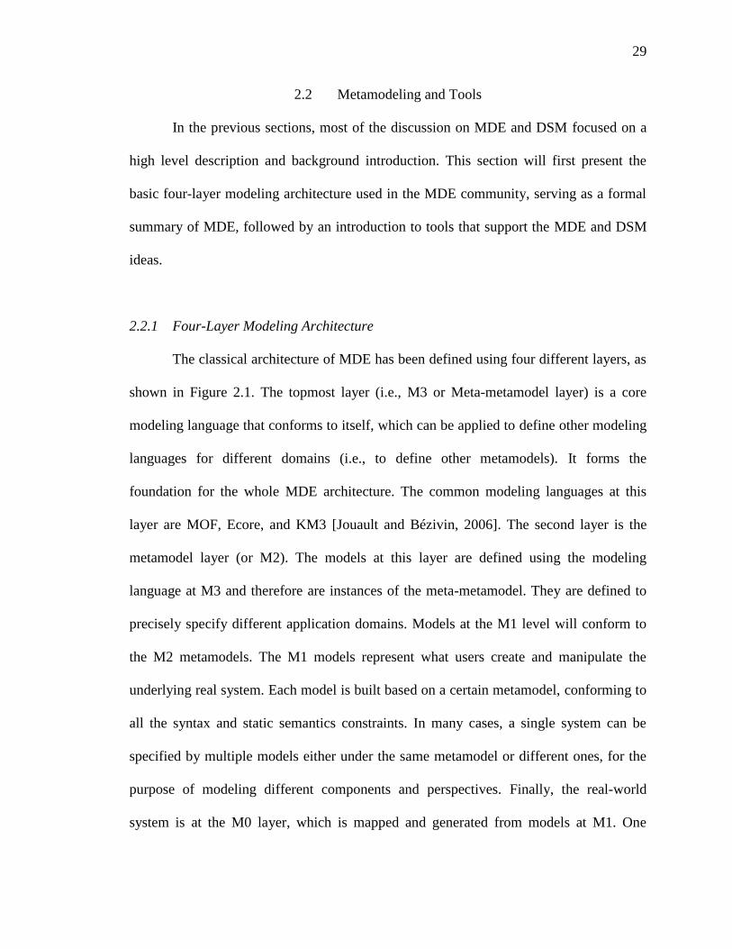
2.2.1 Four-Layer Modeling Architecture ............................................................. 29
2.2.2 Metamodeling Tools ................................................................................... 31
2.3 Model Transformation and Model Transformation Languages ......................... 33
2.3.1 Categories of Model Transformation Languages ....................................... 34
2.3.2 Examples of MTLs ..................................................................................... 36
2.4 End-User Programming (EUP) .......................................................................... 41
2.4.1 Examples of EUP ........................................................................................ 43
3 MODEL TRANSFORMATION BY DEMONSTRATION:
AN END-USER CENTRIC MODEL TRANSFORMATION APPROACH ........ 45
3.1 Overview of Model Transformation By Demonstration (MTBD) ..................... 45
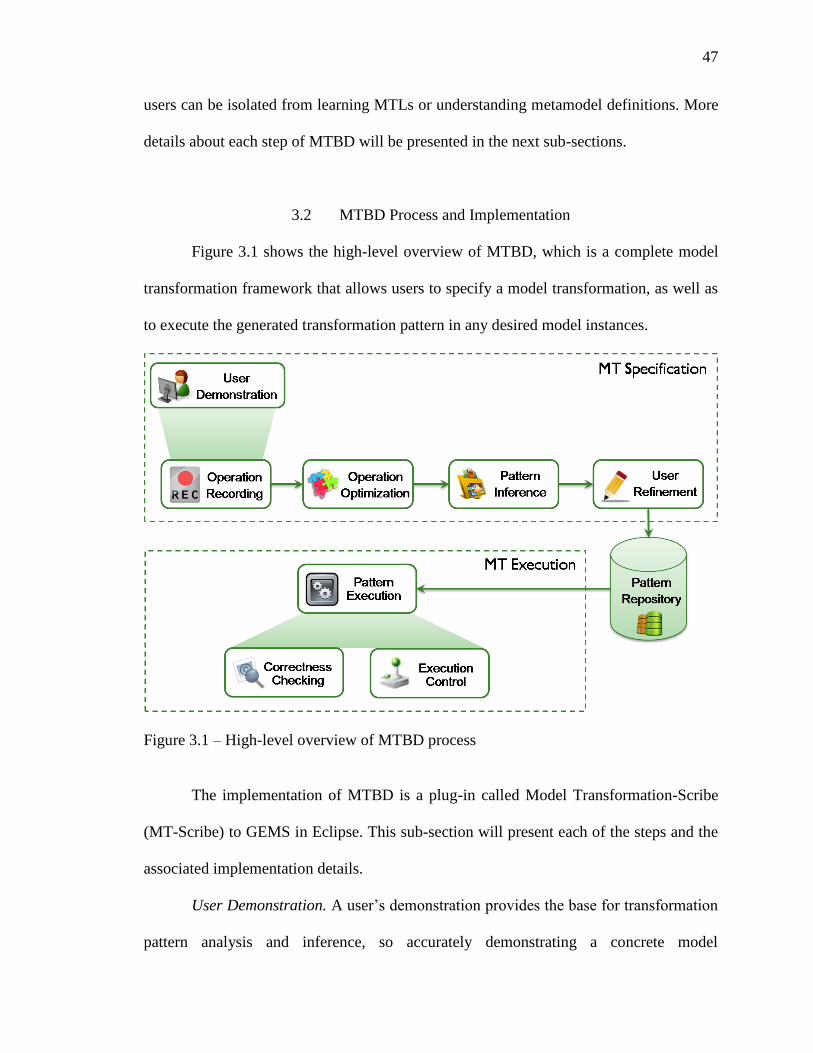
3.2 MTBD Process and Implementation .................................................................. 47
3.3 Formal Specification of MTBD ......................................................................... 60
3.3.1 Operation Demonstration and Recording ................................................... 62
3.3.2 Operation Optimization .............................................................................. 62
3.3.3 Pattern Inference ......................................................................................... 63
3.3.4 User Refinement ......................................................................................... 68
3.3.5 Pattern Execution ........................................................................................ 69
3.4 Related Work...................................................................................................... 69
3.5 Summary ............................................................................................................ 74
4 MTBD IN ACTION: USING MTBD TO SUPPORT MODEL EVOLUTION.... 75
4.1 Model Refactoring.............................................................................................. 75
4.1.1 Case Study – Background ........................................................................... 77
4.1.2 Case Study – Solution ................................................................................. 78
4.2 Model Scalability ............................................................................................... 80
4.2.1 Case Study – Background ........................................................................... 82
4.2.2 Case Study – Solution ................................................................................. 84
4.3 Aspect-Oriented Modeling ................................................................................. 88
4.3.1 Case Study – Background ........................................................................... 90
4.3.2 Case Study – Solution ................................................................................. 94
Page 11
xi
4.4 Model Management............................................................................................ 98
4.4.1 Case Study – Background ........................................................................... 99
4.4.2 Cast Study – Solution................................................................................ 101
4.5 Model Layout ................................................................................................... 103
4.5.1 Case Study – Background ......................................................................... 111
4.5.2 Case Study – Solution ............................................................................... 113
4.6 Experimental Validation .................................................................................. 116
4.6.1 Generality .................................................................................................. 116
4.6.2 Separation from MTLs and Metamodel Definitions ................................. 117
4.6.3 Productivity ............................................................................................... 118
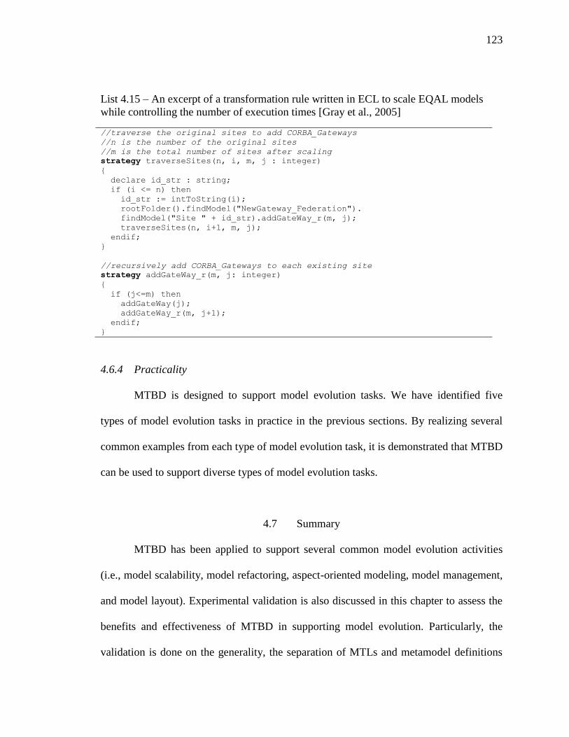
4.6.4 Practicality ................................................................................................ 123
4.7 Summary .......................................................................................................... 123
5 LIVE MODEL TRANSFORMATION BY DEMONSTRATION:
TOOL SUPPORT TO IMPROVE MODEL TRANSFORMATION REUSE .... 125
5.1 Live Model Transformation By Demonstration (Live-MTBD) ....................... 125
5.1.1 Live Demonstration .................................................................................. 127
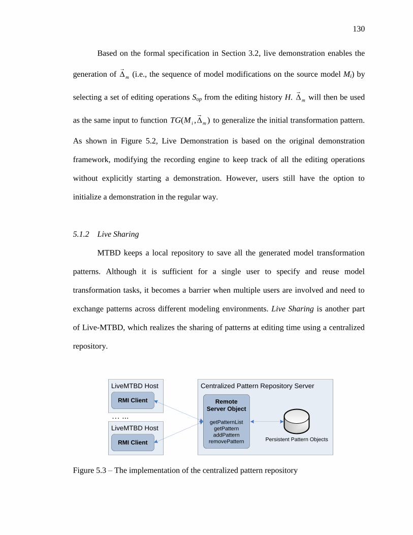
5.1.2 Live Sharing .............................................................................................. 130
5.1.3 Live Matching ........................................................................................... 132
5.2 Case Study ........................................................................................................ 134
5.2.1 Background ............................................................................................... 134
5.2.2 LiveMTBD in Action ................................................................................ 137
5.3 Related Work.................................................................................................... 141
5.4 Conclusion ........................................................................................................ 143
6 MODEL TRANSFORMATION BY DEMONSTRATION DEBUGGER:
AN END-USER FACILITY TO DEBUG MODEL TRANSFORMATION
EXECUTION ....................................................................................................... 145
6.1 Model Transformation By Demonstration Debugger ...................................... 146
6.1.1 Pattern Execution View ............................................................................ 148
6.1.2 Pattern Matching View ............................................................................. 149
6.1.3 Common Bugs and Tracking Solution ...................................................... 149
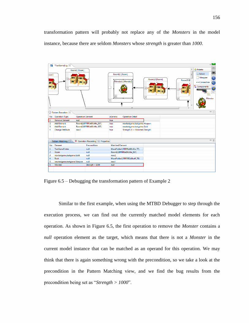
6.2 Case Study ........................................................................................................ 151
6.2.1 Background ............................................................................................... 151
6.2.2 Debugging in Action ................................................................................. 153
6.3 Related Work.................................................................................................... 162
6.4 Conclusion ....................................................................................................... 164
Page 12
xii
7 FUTURE WORK ................................................................................................. 165
7.1 Enhance MTBD Capacity ................................................................................ 165
7.1.1 Supporting Additonal Types of Specification in Demonstration .............. 166
7.1.2 Enable Model Transformation Inference based on Multiple
Demonstrations ......................................................................................... 168
7.2 Improve Live-MTBD Tool Support ................................................................. 169
7.2.1 Enhance the Correctness and User Experience of Live Demonstration ... 169
7.2.2 Add Management Features for Live Sharing ............................................ 170
7.2.3 Improve the Performance of Live Matching ............................................. 171
7.3 MTBD Debugger.............................................................................................. 171
7.4 Apply MTBD to Exogenous Model Transformation ....................................... 172
8 CONCLUSION .................................................................................................... 174
8.1 The MTBD Model Transformation Approach ................................................. 175
8.2 The Live-MTBD Toolkit .................................................................................. 176
8.3 The MTBD Debugger ...................................................................................... 177
LIST OF REFERENCES ................................................................................................ 179
Page 13
xiii
LIST OF FIGURES
Figure Page
1.1 Flexibility versus level of abstraction of programming technologies ...................... 3
1.2 Excerpts of models specified using TTSML ........................................................... 5
1.3 Overview of DSM methodology .............................................................................. 6
1.4 Model evolution in DSM ......................................................................................... 9
1.5 Two types of model transformation – exogenous and endogenous ....................... 10
1.6 Research overview ................................................................................................. 18
2.1 Four layers modeling architecture and tool support .............................................. 30
2.2 An excerpt of an ATL transformation rule ............................................................ 37
2.3 An excerpt of an ECL transformation rule ............................................................ 38
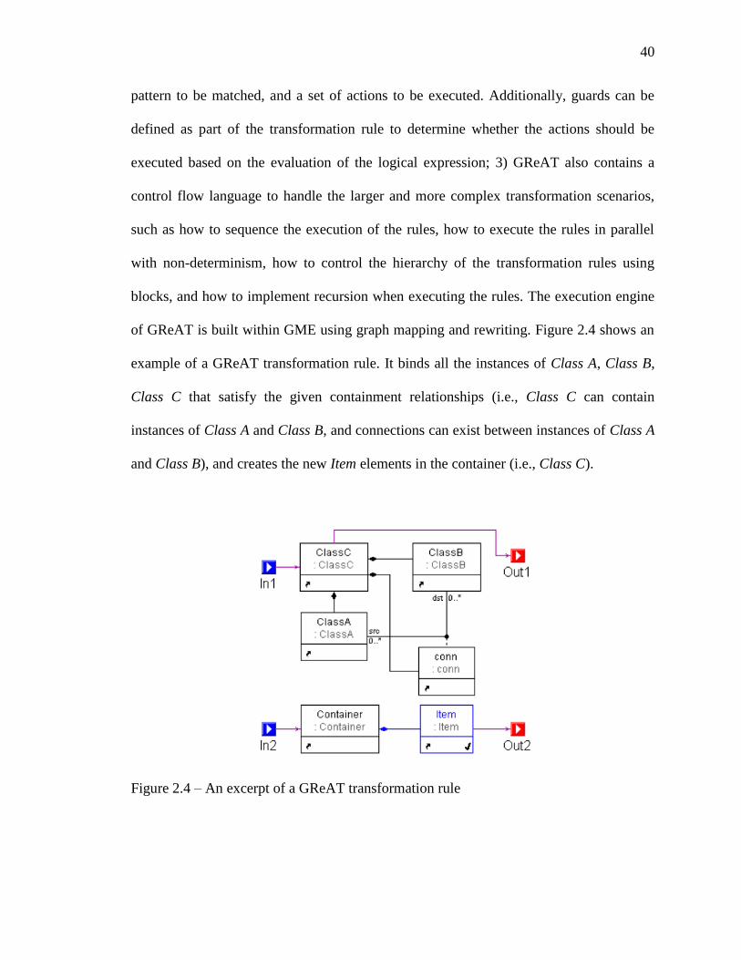
2.4 An excerpt of a GReAT transformation rule ......................................................... 40
3.1 High-level overview of MTBD process ................................................................. 47
3.2 An ongoing demonstration and the Operation Recording view............................. 49
3.3 The attribute refactoring editor .............................................................................. 50
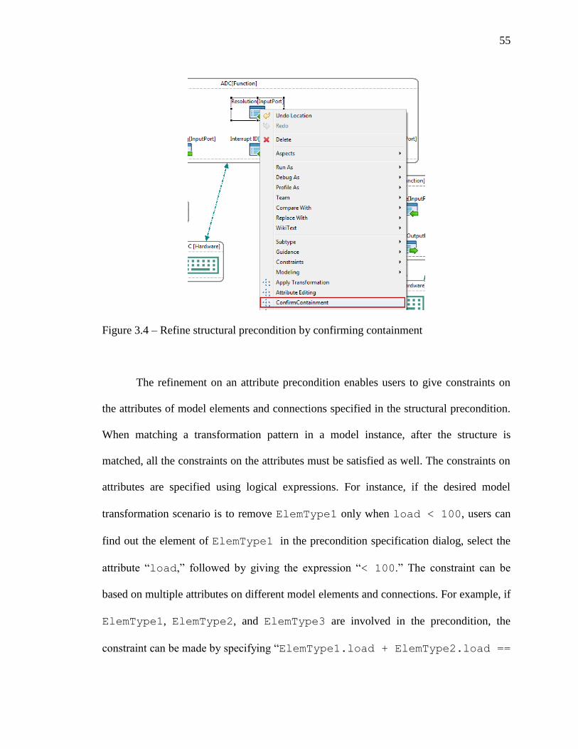
3.4 Refine structural precondition by confirming containment ................................... 55
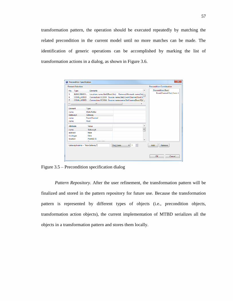
3.5 Precondition specification dialog ........................................................................... 57
3.6 Generic operations identification dialog ................................................................ 58
3.7 Execution controller dialog .................................................................................... 59
4.1 Model refactoring for state diagram ...................................................................... 76
4.2 UML refactoring - Extract Superclass ................................................................... 78
4.3 An SRN model before and after scaling ................................................................ 84
Page 14
xiv
4.4 The process of scaling a SRN model from two events to three events .................. 86
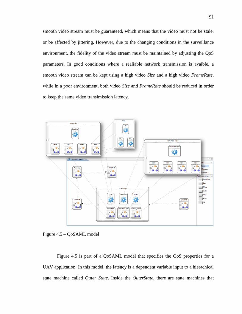
4.5 QoSAML model..................................................................................................... 93
4.6 Two state transition protocols to adapt to environment ......................................... 93
4.7 A QoSAML model after applying the Priority Exhaustive protocol ..................... 94
4.8 Demonstration of adding a transition and setting up the attributes for the new
transition ................................................................................................................ 95
4.9 The initial generalized transformation pattern ....................................................... 97
4.10 The final generated transformation pattern after user refinement ......................... 97
4.11 Two options to control application instances......................................................... 99
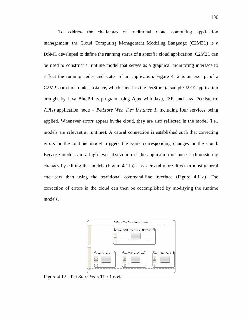
4.12 Pet Store Web Tier 1 node ................................................................................... 100
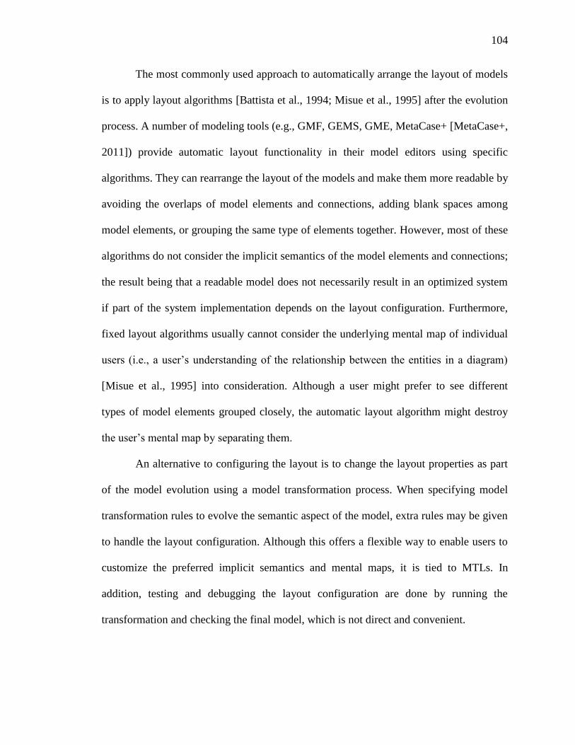
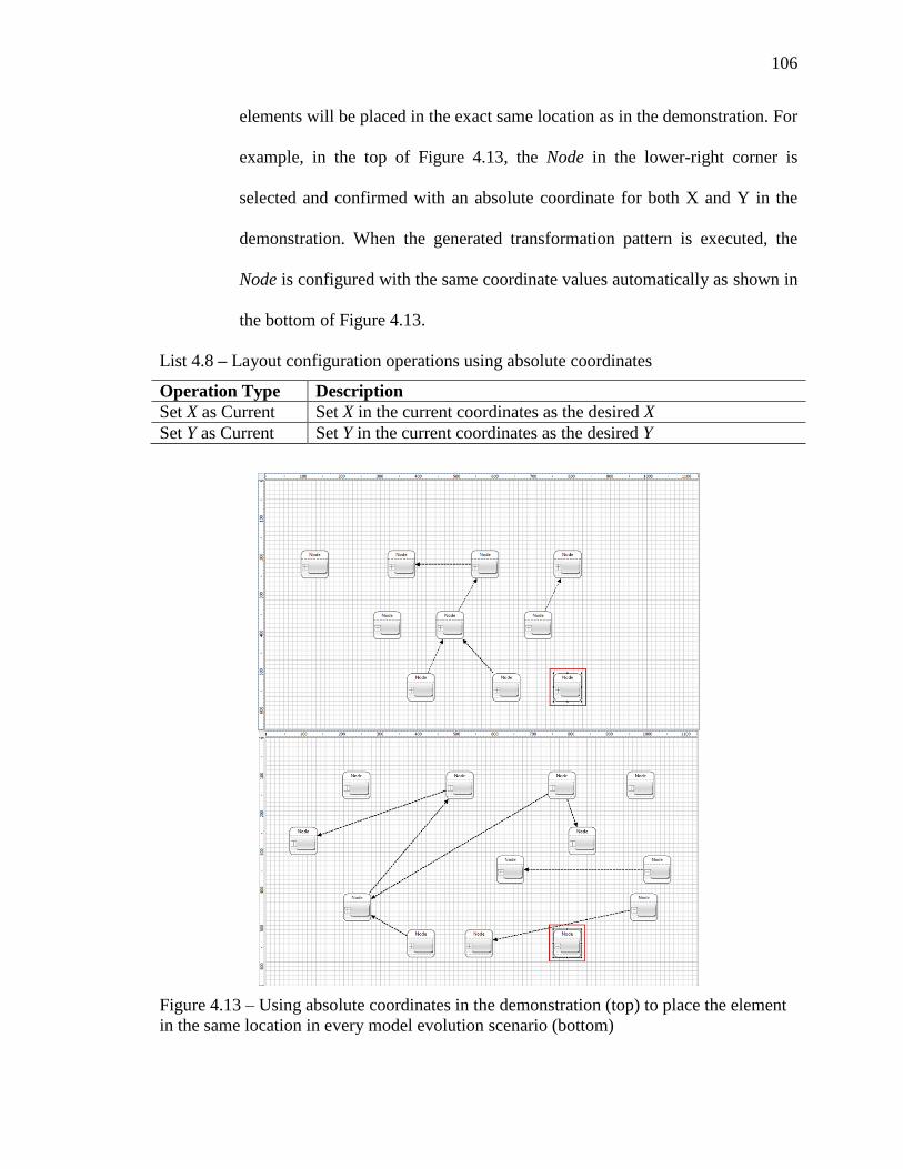
4.13 Using absolute coordinates in the demonstration to place the element in the
same location in every model evolution scenario ................................................ 106
4.14 Using coordinates relative to the boundary of the existing model in the
demonstration to place the element in the location relative to the existing
model in every model evolution scenario ............................................................ 108
4.15 Using coordinate relative to the other model elements in the demonstration to
place the element in the location relative to the same model elements in every
model evolution scenario ..................................................................................... 110
4.16 Different layout configurations of SRN models .................................................. 112
4.17 The layout demonstration in action for the first motivating example .................. 114
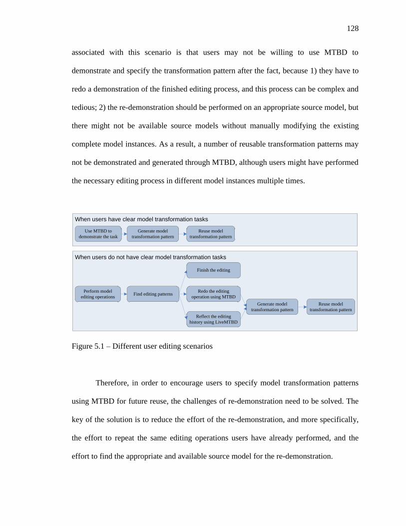
5.1 Different user editing scenarios ........................................................................... 128
5.2 The overview of Live-MTBD toolkit .................................................................. 129
5.3 The implementation of the centralized pattern repository ................................... 130
5.4 EmFuncML models before (top) and after (bottom) applying Buffering
function ................................................................................................................ 135
5.5 Live demonstration enables demonstration by checking the editing history ....... 138
5.6 Final transformation pattern for CreateADC ....................................................... 139
5.7 Pattern execution controller to show all the patterns from a centralized
repository ............................................................................................................. 140
5.8 Live matching suggests applicable transformations in the current selection ....... 141
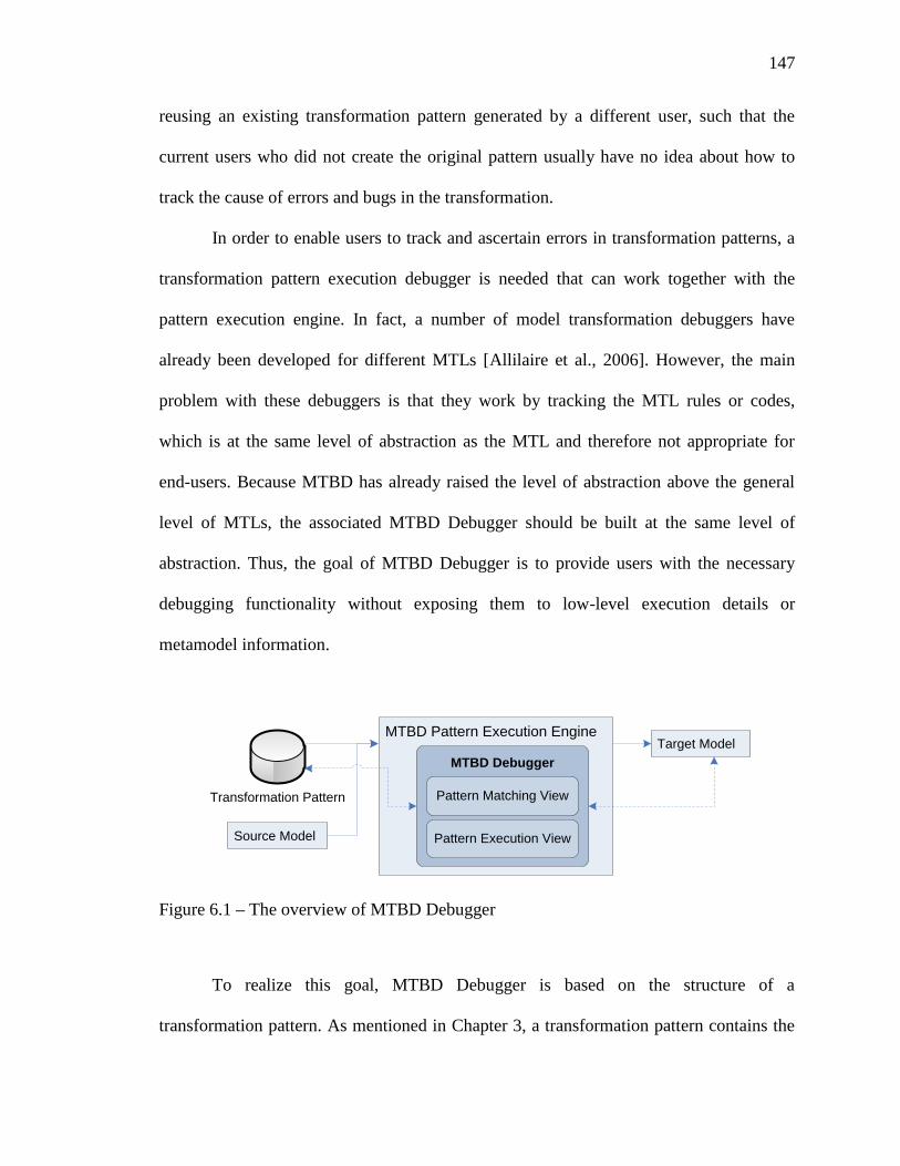
6.1 The overview of MTBD Debugger ...................................................................... 147
Page 15
xv
6.3 The excerpt of a MazeGame model before and after replacing the monster ....... 153
6.4 Debugging the transformation pattern of Example 1 ........................................... 155
6.5 Debugging the transformation pattern of Example 2 ........................................... 156
6.6 The excerpt of a MazeGame model before and after removing all Gold ............ 157
6.7 Debugging the transformation pattern of Example 3 ........................................... 158
6.8 Debugging the transformation pattern of Example 4 ........................................... 159
6.9 The excerpt of a MazeGame model before and after doubling the new weapon 160
6.10 Debugging the transformation pattern of Example 5 ........................................... 161
Page 16
xvi
LIST OF LISTINGS
Listing Page
4.1 Operations for demonstrating Extract Superclass .................................................. 80
4.2 Operations for demonstrating Sub-task t1 of model scalability example .............. 85
4.3 Operations for demonstrating Sub-task t2 of model scalability example .............. 87
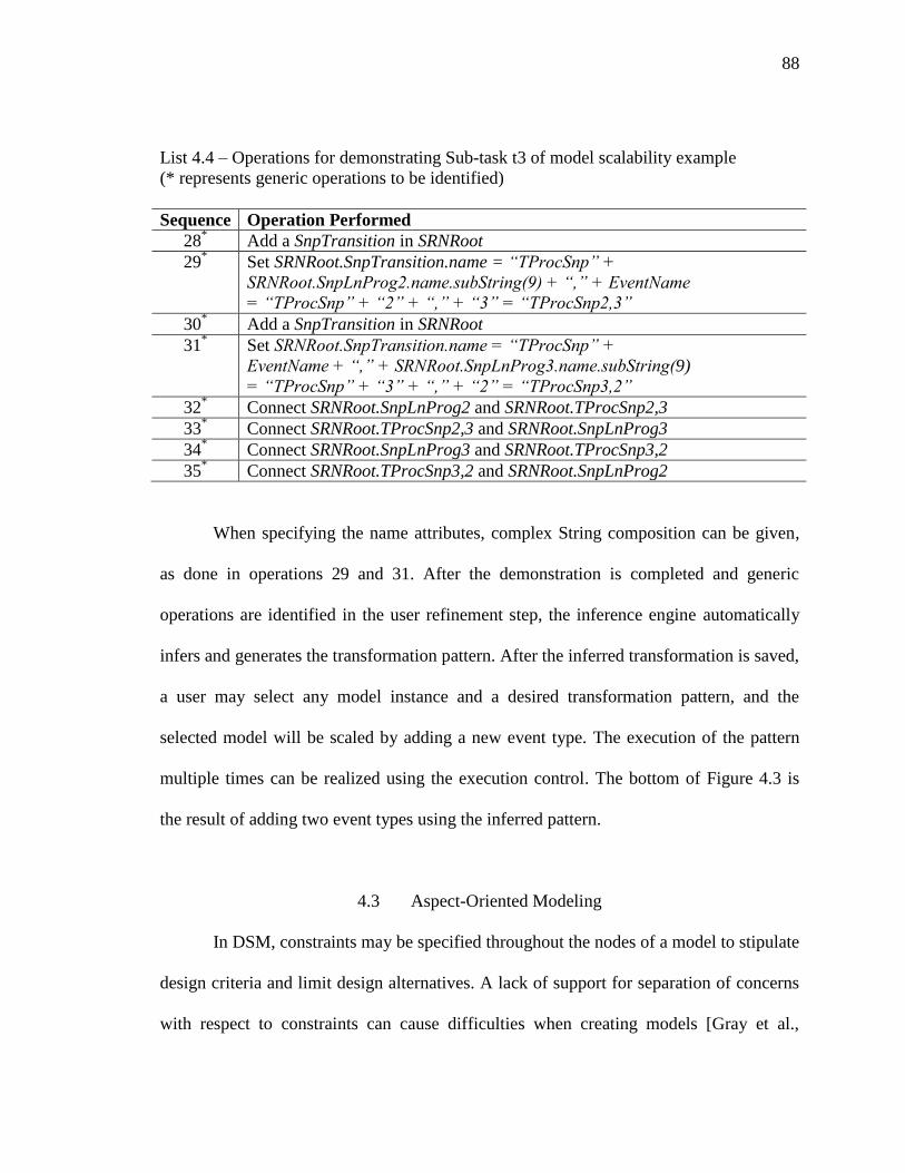
4.4 Operations for demonstrating Sub-task t3 of model scalability example .............. 88
4.5 Operations for demonstrating weaving protocol aspects ....................................... 95
4.6 Refinement operations performed in the demonstration of weaving aspects ........ 96
4.7 Operations for demonstrating model management example ............................... 102
4.8 Layout configuration operations using absolute coordinates............................... 106
4.9 Layout configuration operations using relative coordinates to model boundary . 107
4.10 Layout configuration operations using relative coordinates to model
element(s) ............................................................................................................. 109
4.11 Operations to configure layout demonstration for part one of the motivating
example ................................................................................................................ 115
4.12 Operations to configure layout demonstration for part two of the motivating
example ................................................................................................................ 115
4.13 Operations to configure layout demonstration for part three of the motivating
example ................................................................................................................ 116
4.14 Excerpt of the ECL code to weave aspects to QoSAML models ........................ 122
4.15 An excerpt of a transformation rule written in ECL to scale EQAL models
while controlling the number of execution times ................................................ 123
6.1 Operations for demonstrating replacing a Monster ............................................. 154
6.2 Operations for demonstrating removing all pieces of Gold ................................. 157
6.3 Operations for demonstrating replacing a Monster and doubling the strength .... 161
Page 17
xvii
LIST OF TABLES
Table Page
3.1 The types of operations and the related context information recorded .................. 52
4.1 Attributes of PetStore Web Tier Instance 1 (Overloaded Node) ......................... 101
4.2 Comparison of accomplishing model transformation tasks using three
approaches............................................................................................................ 119
Page 18
xviii
LIST OF ABBREVIATIONS
ADC Analog-to-Digital Converter
AOM Aspect-Oriented Modeling
AOP Aspect-Oriented Programming
API Application Programming Interface
ATL Atlas Transformation Language
C2M2L Cloud Computing Management Modeling Language
CASE Computer-Aided Software Engineering
CDL Contract Description Language
COM Component Object Model
CORBA Common Object Request Broker Architecture
CRUD Create/Read/Update/Delete
C-SAW Constraint-Specification Weaver
CWM Common Warehouse Metamodel
DRE Distributed Real-time and Embedded
DSM Domain-Specific Modeling
DSL Domain-Specific Language
DSML Domain-Specific Modeling Language
ECU Electronic Control Unit
ECL Embedded Constraint Language
Page 19
xix
EMF Eclipse Modeling Framework
EmFuncML Embedded Function Modeling Language
EMP Eclipse Modeling Project
EQAL Event Quality of Service Aspect Language
ESML Embedded Systems Modeling Language
EUP End-User Programming
FSM Finite State Machine
GEMS Generic Eclipse Modeling System
GEF Graphical Editing Framework
GME Generic Modeling Environment
GMF Graphical Modeling Framework
GPL General-purpose Programming Language
GREAT Graph Rewrite And Transformation
GUI Graphical User Interface
HTML Hypertext Markup Language
J2EE Java Platform Enterprise Edition
JSF Java Server Faces
KM3 Kernel Meta-Meta Model
LHS Left-Hand Side
Live-MTBD Live-Model Transformation By Demonstration
M2T Model-to-Text
MDA Model-Driven Architecture
MDE Model-Driven Engineering
Page 20
xx
MOF Meta-Object Facility
MTBD Model Transformation By Demonstration
MTBE Model Transformation By Example
MTL Model Transformation Language
MT-Scribe Model Transformation-Scribe
NAC Negative Application Condition
OCL Object Constraint Language
OMG Object Management Group
OSM Operation Specification Model
PBE Programming By Example
PIM Platform-Independent Model
QoS Quality of Service
QoSAML QoS Adpation Modeling Language
QVT Query View Transformations
RHS Right-Hand Side
RMI Remote Method Invocation
SLOC Source Lines Of Code
SRN Stochastic Reward Net
SRNML Stochastic Reward Net Modeling Language
TGG Triple Graphical Grammar
TN Transformation Net
TTSML Time-Triggered System Modeling Language
UAV Unmanned Aerial Vehicle
Page 21
xxi
UML Unified Modeling Language
VE Visual Editor
VPL Visual Programming Language
WCET Worst Case Execution Time
WYSIWYG What You See Is What You Get
XML Extensible Markup Language
XMI XML Metadata Interchange
XSLT Extensible Stylesheet Language
Page 22
1
CHAPTER 1
INTRODUCTION
Software development is an inherently challenging process, resulting from both
essential and accidental complexities [Brooks, 1987]. The essential complexities of
software are reflected in the difficulty of understanding the problem, designing and
testing the conceptual construct, as well as the characteristics of software, such as
invisibility, changeability and conformity. The accidental complexities represent the
challenges on the concrete software implementation and testing processes. In the past
several decades, much effort has been made to help software developers and engineers
address these complexities, in order to increase the productivity, simplicity and reliability
of software development.
Among all the effort, one of the most frequently applied and effective approaches
is to raise the level of programming language abstraction by capturing only the details
relevant to the current computing perspective, but hiding the underlying implementation
information [Lenz and Wienands, 2006]. As shown in Figure 1.1, from machine code to
assembly language, high-level and object-oriented programming languages, although
programmers generally lose fine-grained control of the underlying machine as abstraction
increases (e.g., direct memory address control is not feasible using Java while it can be
implemented using C effectively), they are enabled to better focus on the specific
Page 23
2
problems they want to solve, while being isolated from irrelevant low-level
implementation details [Greenfield and Short, 2004].
With the complexity and scale of software systems increasing dramatically [Lenz
and Wienands, 2006], a new and higher level of abstraction is needed to continue
alleviating the difficulties encountered in the complex software development process. A
notable and promising approach is Model-Driven Engineering (MDE) [Schmidt, 2006],
which decouples the description of the essential characteristics of a problem from the
details of a specific solution space (e.g., middleware, programming languages).
MDE promotes the general idea of using models at different levels of abstraction
to define systems, and automate the transformation process between different levels of
models and the final implementation code. As a concrete and mainstream MDE
methodology, Domain-Specific Modeling (DSM) [Gray et al., 2007] uses a Domain-
Specific Modeling Language (DSML) [Lédeczi et al., 2001] to declaratively define a
software system using specific domain concepts, and automatically generate the desired
software artifacts (e.g., programming code, simulation script, XML deployment
description) by model transformation engines and code generators. Using DSM, software
developers and engineers, or even end-users (e.g., domain experts), are enabled to
program in terms of their unique intentions and understanding of a specific problem
domain, rather than focusing on solutions that are intertwined with the underlying
computing environment [Schmidt, 2006].
Page 24
3
Java, C
#
Assem
bly
Lan
guag
e
C
Mach
ine C
ode
Abstraction
Model-D
riven
Engin
eering
Flex
ibility
Figure 1.1 – Flexibility versus level of abstraction of programming technologies
1.1 Domain-Specific Modeling (DSM)
DSM reaches a new level of abstraction by focusing on the specific problem
domains using DSMLs so that the design space is narrowed down and the associated
complexities are reduced. A problem domain can be any of the areas that require software
solutions, such as automobile, telecommunication, health care, industry, robotics, energy
or finance. It can also vertically include the different aspects of system development,
such as user interface, functional properties, non-functional properties, user work flow, or
data persistency. Additionally, any of these domains can be divided into smaller problems
or tasks, which can be considered as a separate sub-domain.
A DSML is designed for a single problem domain, which only contains the
concepts related with the specific problems to solve, rather than the underlying
implementation details. The metamodel [Atkinson and Kuhne, 2003] is used to specify
the entities, associations and constraints for the DSML, having a similar role as a
Page 25
4
grammar to specify the syntax for a programming language. The metamodel can be used
to generate a modeling environment, in which users are enabled to build concrete models
to represent the system for the application domain. The models built by users must
conform to the definition of the metamodel. Figure 1.2 shows a DSML called TTSML
(Time-Triggered System Modeling Language) [Sun et al., 2011-c] used to specify the
data communication system used inside electric automobiles. It provides the basic
modeling elements such as ECU (Electronic Control Unit), Channel, Controller,
Functional Unit, Timing Requirement. Users of TTSML can specify the desired system
by constructing the model using these concepts directly. For example, as shown in Figure
1.2, three ECUs (i.e., SimulatorPC, DrvierAssistance, DriverInferfaceAndSensor) are
connected to both Channel A and Channel B; different function units (e.g.,
BrakeAssistant, ReadGasPedalPosition) are running on these ECUs and communicate
with each other based on different timing requirements (e.g., Safety Critical,
LowSpeedSensor). The low-level implementation details about how to configure the
ECUs with the APIs provided by the manufacturer, how to implement the correct data
transmission protocol, or how to make the correct function calls to ensure the timing
requirements are hidden to users. In other words, users only need to think about the
concrete problem space – what system functionalities are needed, what system
performance properties are desired, rather than the solution space (i.e., how to implement
the actual system).
Page 26
5
Figure 1.2 – Excerpts of models specified using TTSML
The solution space is handled by code generators associated with the DSML. A
code generator [Kelly and Tolvanen, 2008] takes models built by users as input, and
produces low-level implementation artifacts as output. Multiple code generators or model
interpreters might exist for a single DSML, which can be used to generate the code for
Page 27
6
different platforms or software artifacts. Taking TTSML as an example, two code
generators are available to generate the implementation code for two hardware platforms:
Freescale S12 Microcontroller [Freescale, 2011] and Eberspächer FlexRayCard
[Eberspächer, 2011]; another generator is used to generate the XML configuration for the
protocol implementation. In some other DSM applications, code generators have also
been applied to produce HTML files, property files, graphical charts and tables, or even
software documents [Kelly and Tolvanen, 2008], as shown in Figure 1.3.
Figure 1.3 – Overview of DSM methodology
The main benefit of DSM comes from its ability to describe the properties of a
system at a high-level of abstraction and in a platform-independent notation, and protect
key intellectual assets from technology obsolescence, resulting in less effort and fewer
low-level details to specify a given system. Compared with the traditional usage of
software models and code generation techniques, DSM distinguishes itself by pursuing
Page 28
7
automated code generation without further modifications, so that users are completely
isolated from the low-level implementation details. Otherwise, DSM will not raise the
level of abstraction for domain experts. UML [UML, 2011] models, for instance, are
often used either as a design blueprint for software developers to write code, or as a basis
to generate the initial code framework (e.g., class definitions and method signatures) with
the inner implementation part to be filled manually.
Furthermore, by raising the level of abstraction, DSM helps to improve end-user
programming [Burnett et al., 2004], and therefore reduces the chance of software failures
due to miscommunications between software engineers and end-users. In the traditional
software development process, a knowledge and expertise gap between software
developers and different domain experts exists, the negative consequence being that
developers who are skilled at programming may not fully and correctly understand the
user’s requirements, while the users who know their problem domain very well may have
no idea about how to build the desired software system. However, in DSM, because the
system can be represented by high-level and domain-specific models rather than general-
purpose programming languages, end-users who have no knowledge or experience in
programming are enabled to participate in the software system development process,
making more accurate and valuable decisions in software design, implementation, and
maintenance [Kelly and Tolvanen, 2008].
1.2 Model Evolution in DSM
Software evolution is an inevitable and essential activity in software development.
As noted by Lehman, “Software that is being used must be continually adapted or it
Page 29
8
becomes progressively less satisfactory” [Lehman, 1978]. In the context of DSM, models
replace source code as the first-class entities in the software development process and
represent the initial point for the generation of low-level artifacts. Therefore, if a system
needs to evolve and adapt to new requirements, instead of changing source code directly,
the models representing the system should be evolved first according to the need, which
then leads to a re-generation of the low-level code or other artifacts [Lin et al., 2007].
Figure 1.4 shows a model evolution scenario. A metamodel has been defined for a
problem domain, and Model0 is the initial model that conforms to the metamodel, which
generates the first version of the source code (Code0) for the system. As the new
requirements come from the problem domain, Model0 has to be changed and evolved to
new versions (Model1, Model2, … Modeln,) to adapt the new requirements, so that the
corresponding changes can be reflected in Code1, Code2, … Coden by triggering the
code generation process from each new model. This dissertation research focuses on
addressing the problems and challenges associated with implementing the model
evolution process, while involving end-user participation.
A number of scenarios can trigger the evolution of models, such as adding /
removing / updating a certain functionality for an existing system [Greenfield and Short,
2004], weaving a new aspect (e.g., logging, constraint checking) into the base system
[Elrad et al., 2002; Gray et al., 2006], scaling the system from a base state to a complex
state [Lin et al., 2008], and optimizing the internal structure (e.g., refactoring) [France et
al., 2003]. Clearly, model evolution is as essential as traditional code evolution in a
software development process. In fact, some other model evolution issues also exist in
the context of DSM; for instance, evolving a model to a different domain [Jouault and
Page 30
9
Kurtev, 2005], metamodel evolution [Sprinkle, 2003; Narayanan et al., 2009], model
interpreter evolution [Zhang et al., 2004], and model evolution by changing the
corresponding code (i.e., reverse engineering) [Rugaber and Stirewalt, 2004]. However,
the research described in this dissertation particularly focuses on model evolution from
one state to another and from one version to another version within the same metamodel.
The typical evolution activities in this category are model refactoring [Zhang et al.,
2005], model scalability [Lin et al., 2008], aspect-oriented modeling [Zhang et al., 2007],
model management [Deridder et al., 2008], and model layout configuration [Sun et al.,
2011-b].
MetaModel
Model0 Model1 Modeln
Conform To
Code0 Code1 Coden
Generate Generate Generate
∆M1 ∆M2 ∆Mn
∆C1 ∆C2 ∆Cn
… …
… …
Figure 1.4 – Model evolution in DSM
1.3 Model Transformation and Model Transformation Languages (MTLs)
Model transformation [Sendall and Kozaczynski, 2003] is a core technology in
DSM. It receives a source model that conforms to a given source metamodel as input, and
produces as output another model conforming to a given target metamodel. When the
Page 31
10
source and target metamodels are different (i.e., between two different domains), the
transformation is called exogenous, as shown in Figure 1.5a (e.g., a UML class diagram
model is transformed to a relational data model [Shah and Slaughter, 2003]). If the source
and target metamodels are identical, the transformation is called endogenous, as shown in
Figure 1.5b (e.g., a UML class diagram model is transformed from one state to another
state through a “Pull Up Method” refactoring process [Fowler, 1999]).
Because the essence of model transformation is to transform and change a model,
there is a direct connection between model transformation and model evolution. Actually,
model evolution tasks as discussed in this dissertation can be regarded as a model
transformation process, or more precisely, an endogenous model transformation process,
because both the source model (e.g., Model0 in Figure 1.4) and the target model (e.g.,
Model1 in Figure 1.4) in a model evolution conform to the same metamodel.
MetaModel 1 MetaModel 2
Model Instance 2Model Instance 1
Conforms To Conforms To
Transform To
Transform To
MetaModel 1
Model Instance 1 Model Instance 2
Conforms To Conforms To
Transform To
a. Exogenous Model Transformation b. Endogenous Model Transformation
Figure 1.5 – Two types of model transformation – exogenous and endogenous
The benefit of connecting model evolution with model transformation is that a
number of model transformation tools and technologies can be utilized to support model
evolution tasks. The traditional approach to realize a model transformation is to use an
executable model transformation language. A Model Transformation Language (MTL)
Page 32
11
[Sendall and Kozaczynski, 2003] is usually a Domain-Specific Language (DSL) [Mernik
et al., 2005; Sun et al., 2008] particularly used for model transformation tasks. A set of
transformation rules can be defined in a MTL to specify how a source model should be
transformed into a target model. More specifically, the rules define how the source model
should be mapped to the target model, and the scope where the rules can be applied.
These rules are often defined at the metamodel level rather than to a specific model
instance, so that they are capable of carrying out the desired transformation process
automatically on any model that conforms to the same metamodel.
MTLs can be either graphical or textual, and most of them are at a higher level of
abstraction than General-purpose Programming Languages (GPLs), such as Java or C++.
MTLs support either an imperative, declarative, or hybrid approach to specify a
transformation task. Some popular MTLs in this category are QVT [QVT, 2010], ATL
[Jouault et al., 2008], and ECL [Gray, 2002]. Using MTLs, automated model evolution
processes can be implemented by specifying and executing the model transformation
rules on how to evolve a model from one state to another state, or from one configuration
to another.
1.4 Key Challenges in Supporting Model Evolution
As discussed in the previous sections, model evolution is an essential and
inevitable activity in DSM. However, the tools to support model evolution have not been
well developed. In current DSM practice, model evolution tasks are mainly implemented
and automated using MTLs. Although MTLs are powerful and expressive to handle
various kinds of model evolution tasks, it is not always the perfect solution due to some
Page 33
12
challenges related to end-user friendliness, the mechanism of exchanging and reusing
model evolution knowledge, and debugging support. The following subsections outline
the challenges that this dissertation focuses on with respect to current model evolution
practice.
1.4.1 The Difficulty of Learning and Using MTLs for End-Users
Although a number of powerful MTLs have been developed to support various
types of model evolution tasks in different modeling tools and platforms, learning and
using these languages is by no means an easy task, particularly for general end-users
including domain experts and non-programmers who are not familiar with MTLs or
GPLs. The emphasis on enabling this group of users to implement model evolution tasks
results from the fact that end-users can participate in the software development process
using DSM, and in many cases, they know the exact model evolution tasks in need.
However, this group of users might be prevented from contributing to these tasks from
which they have much domain experience due to the difficulty of learning and using
MTLs as described throughout this subsection.
The steep learning curve for MTL adoption. Most MTLs are high-level languages
and specific to model transformation tasks, but a steep learning curve is still inevitable
due to the complexity of learning the syntax, semantics, special features or concepts,
associated libraries, and the editing or execution environment of a MTL. This challenge
is particularly true for those who have never had MTL or programming language training.
Moreover, in many cases, in order to correctly use a MTL, users are required to
learn not only its basic usage of how to transform models, but also some additional
Page 34
13
knowledge that is not directly related with model transformations. For example, ECL
integrates some general programming concepts, such as variable declarations (e.g.,
declare node : object;), and branch statements (e.g., if (idx<=max)
then); ATL applies Object Constraint Language (OCL) [OCL, 2010] expressions to
give specific constraints on the precondition of model transformations. Learning these
may not be very challenging to a computer scientist, a software developer or a model
engineer, but it is definitely a hindering barrier to general end-users like domain experts
and non-programmers.
In addition, the diversity of MTLs introduces a number of different model
transformation design approaches, bringing about a challenge toward achieving a uniform
MTL learning process. For instance, with declarative MTLs (e.g., ATL), users can focus
on the mapping relationships between the source and target models, ignoring the details
underlying those mappings; but many powerful MTLs (e.g., ECL) also support
imperative mechanisms, which means that users need to think about how a model should
be changed and transformed to the target desired state; some other MTLs (e.g., EMF
Tiger [Biermann et al., 2006; EMF Tiger, 2010], GReAT [Agrawal, 03]) are based on
graph theory, such as graph matching and graph rewriting, and users are expected to think
of model transformation processes in terms of graphs. Thus, even being familiar with a
certain MTL cannot guarantee a gradual adoption curve for learning a second MTL.
The difficulty of understanding metamodels. A metamodel, as explained in
Section 1.1, serves as the abstract syntax of a DSML, and precisely specifies how the
models should be constructed in a particular domain. Using most MTLs, the model
transformation rules are often defined at the metamodel level rather than the concrete
Page 35
14
model instance level. However, developing a deep and clear understanding of a
metamodel is challenging, especially for large and complex domains.
The need to define transformation rules at the metamodel level results from the
gap existing between the way a user recognizes models and the way a computer does
[Wimmer et al., 2007]. Typically, users reason on models that represent real-world
examples shown by concrete syntax and mappings between semantically corresponding
model elements according to the specific transformation scenarios. However, this way of
thinking is not appropriate for precisely defining model transformations with currently
available MTLs, because instead of writing transformation rules working for one specific
model example, users expect the rules to be generic so that they can be reused on other
models for the same transformation purpose. Currently, the most effective way to realize
this goal is to define the generic rules in terms of metamodel definitions for the models to
be transformed.
Understanding metamodels becomes even more challenging when some concepts
in a particular domain are hidden in the metamodel definition and difficult to unveil
[Kappel, 2006]. This is because not all concepts in a domain can be represented as first-
class constructs in the metamodel. Some domain concepts may be hidden in attributes or
association ends in the metamodels. The consequence is that users are required to
correctly uncover these hidden concepts and use them in the transformation rules that
they write.
Thus, if model transformations can be specified and implemented without
explicitly understanding the full details of a metamodel, users could avoid the extra
burden of understanding the complex and abstract metamodel definitions.
Page 36
15
1.4.2 Limited Tool Support to Exchange and Reuse Model Evolution Knowledge
Similar to traditional software development, specifying a complex system using
DSM usually requires collaboration [Redmiles et al., 2004]. A DSML may be used to
describe different aspects of a system (e.g., a DSML designed to model embedded
systems [Sun et al., 2011-a] enables users to specify the system from the perspectives of
both the hardware configuration and the software functional logic), and users might come
from different areas with different expertise. Even for the same perspective and the same
area, users may have different levels of experience and knowledge (e.g., a senior engineer
is more likely to produce higher quality models or provide better modeling solutions in
most cases than a junior engineer). When it comes to model evolution tasks in a diverse
and collaborative modeling environment, it is essential to enable different users to share,
exchange their knowledge and experience, as well as enable the reuse of the knowledge
(e.g., a software engineer may need to reuse the hardware engineer’s knowledge about
evolving a part of the hardware configuration; a junior engineer may need the senior
engineer’s experience to validate models and fix errors). Unfortunately, tool support in
this area is very limited in the current practice.
When using MTLs to implement model evolution tasks, each set of the executable
model transformation rules can be regarded as the persistent knowledge for a certain
evolution task. Executing the rules on different models actually realizes knowledge reuse.
However, for most MTL tools, there is no mechanism to load and execute the
transformation rules specified by different users at editing time. For instance, ATL
provides an online collection of the commonly used model transformation scenarios
Page 37
16
(ATL transformation zoo [ATL Transformation Zoo, 2011]), where users can download
the rules and execute them in their own environments. Obviously, this is by no means the
desired approach to exchange and reuse knowledge, because a large number of model
evolution tasks can be created during the editing time, which at the same time, are needed
to be shared and reused by different users. Using a static online collection cannot satisfy
the need to acquire the correct evolution knowledge promptly.
Moreover, the presence of reusable model evolution knowledge does not
guarantee that it can be reused correctly by users who need them. On one hand, users
might not know that certain model evolution tasks they need to accomplish have already
been created and shared, so that they might end up manually implementing the task again.
On the other hand, even if users know the presence of certain model evolution knowledge
that can be potentially reused, how to determine whether it is the right knowledge to
reuse or whether it is applicable to their own scenarios is another challenging problem. In
the current practice, users may decide to reuse an available model evolution task either by
reading and understanding the textual description about the evolution rules, or by directly
executing and comparing the results. The negative consequence is that users are very
likely to reuse the wrong knowledge due to the misunderstanding of an inaccurate textual
description, destroy the current model or import accidental errors by executing the wrong
evolution rules. Thus, enabling users to identify the correct and available knowledge to
reuse in a timely manner plays an important role in supporting model evolution
knowledge exchange and reuse.
Page 38
17
1.4.3 The Lack of an End-User Debugging Facility for MTLs
Because model transformation specifications are written by humans and
susceptible to errors, the need for testing and debugging mechanisms for MTLs are as
important as the similar need with general-purpose programming languages. Although
testing offers some confidence about whether the model is in the desired state after being
transformed, debugging helps users to examine the transformation process and track
potential errors.
Recently, some algorithms and tools have been developed to support model
transformation testing by model comparison, which have demonstrated initial results in
automating the testing process [Lin et al., 2005; Lin et al., 2007]. However, model
transformation debugging is still a weak area with limited results. Most modeling tools or
platforms only provide an editing and execution environment for a supported MTL
without enabling users to track and monitor the execution of transformation rules and the
result. When errors occur, the most common way to fix the error is to check the model
after a transformation and locate the erroneous model elements, attributes or connections,
and then go back to the corresponding transformation rules to check the potential errors.
This process will iterate until the model is transformed to the desired state. Because most
MTLs do not support common constructs available in GPLs, the debugging process
becomes more challenging if a debugger is not present in the modeling tool or execution
engine.
Without the assistance of a debugger, error recovery becomes tedious and error-
prone, particularly when the model being transformed is large and a lot of complex
transformation rules are involved in the model evolution task. Although some MTL tools
Page 39
18
already have associated debuggers [Jouault et al., 2008; Balasubramanian et al., 2006-a],
the debuggers work by tracking the MTL rules or codes, which are at the same level of
abstraction as the MTL and therefore not appropriate for some categories of end-users.
1.5 Research Goals and Overview
To address the difficulty of supporting model evolution using the traditional
model transformation approaches that rely on MTLs, and enable a wider range of end-
users to participate in model evolution activities through implementing model evolution
tasks, exchanging and reusing model evolution knowledge, and debugging model
evolution execution process, the research in this dissertation provides a user-centric
model transformation approach to implement model evolution tasks with tools to share
and reuse evolution knowledge. Furthermore, this research considers the transformation
debugging issue to assist in determining the correctness and tracking of model
transformation errors. Figure 1.6 shows an integrated view of this research. The overview
of the research is described in the following sections.
Model Transformation By Demonstration (MTBD) (Chapter 3)
End-user Model Transformation Framework
Live-MTBD (Chapter 5)
Evolution Knowledge Exchange and Reuse Tool Support
MTBD Debugger (Chapter 6)
End-User MTBD Debugger
Apply MTBD to Model Evolution (Chapter 4)
Model
Refactoring
Model
Scalability
Aspect-Oriented
Modeling
Model
ManagementModel Layout
Figure 1.6 – Research overview
Page 40
19
1.5.1 Model Transformation By Demonstration (MTBD) to Simplify Model
Transformation
To address the challenges of learning and using MTLs to support model evolution,
a new endogenous model transformation framework has been designed and implemented,
called Model Transformation By Demonstration (MTBD) [Sun et al., 2009-a], which
enables end-users to specify a model transformation by directly performing editing
operations on concrete examples (i.e., to give a demonstration), combined with user
refinement and automatic inference processes. After a user demonstration, a model
transformation pattern is generated as the persistent specification of a model
transformation task. MTBD also includes its own transformation pattern execution engine,
which executes the inferred transformation by pattern matching and automated operation
execution. This framework is different from the traditional MTLs in that no language is
involved in the process and the specification of the rules is realized at the model instance
level rather than the metamodel level, so that users can be isolated from the language
learning curve and the complex metamodel definitions. In other words, the level of
abstraction to implement model transformations is raised, so that the end-users (e.g.,
domain experts and non-programmers) are able to implement the desired model evolution
tasks through demonstration without being exposed to the low-level implementation
details.
1.5.2 Live-MTBD to Improve Model Evolution Knowledge Exchange and Reuse
The second contribution of this research includes “Live” feature extensions to
MTBD (Live-MTBD), which improves the user experience when demonstrating a
Page 41
20
transformation, and more importantly, supports model evolution knowledge sharing,
exchange and reuse. The toolset Live-MTBD contains three components: 1) Live
Demonstration, provides a more general demonstration environment that allows users to
specify editing activities based on their editing history, with the purpose being to
encourage users to create more transformation patterns; 2) in order to improve the sharing
of editing activity knowledge among different users, Live Sharing – a centralized model
transformation pattern repository has been built so that transformation patterns can be
reused across different editors; 3) a live model transformation matching engine – Live
Matching has been developed to automatically match the saved transformation patterns at
modeling time, and provides editing suggestions and guidance to users during the editing
process. Live-MTBD features cooperate seamlessly with MTBD to offer an end-user
friendly, collaborative, and intelligent model evolution environment.
1.5.3 MTBD Debugger to Enable End-User Model Transformation Debugging
To support error tracking and execution monitoring, an MTBD debugger
associated with the MTBD execution engine has been developed. The debugging tool can
offer support for isolating the cause of a transformation error, by enabling users to trace
all the matched locations in the model in an execution of a transformation pattern, and
step through individual actions of the transformation to display the model data intuitively
within the host modeling environment. Users can determine the correctness of the
precondition of the inferred pattern from the matching locations, and the correctness of
the actions of the inferred pattern by watching each of the execution steps. In addition, to
improve end-user friendliness, the MTBD debugger hides the low-level execution
Page 42
21
information or metamodel definitions and focuses only on information at the model
instance level.
1.5.4 Applications of the Research to Support Model Evolution in Practice
The primary purpose of this research is to support various model evolution tasks
using a new model transformation approach. Therefore, the power and functionality of
the approach should be decided and evaluated by focusing on how it can fulfill the
diverse needs of model evolution in practice. The MTBD approach should be applicable
to the core types of model evolution tasks, such as model refactoring, model scalability,
aspect-oriented modeling, model management, and model layout configuration. Thus, the
identification of the special requirements in each type of task and the investigation on
how to apply MTBD to these practical applications is another key contribution in this
research, and demonstrated by various case studies throughout this dissertation.
1.6 The Structure of the Thesis
This chapter has summarized a subset of the research on model evolution in the
context of DSM and the current challenges that exist to support model evolution
activities. Research goals that address these problems have been outlined. Chapter 2
describes background information related to the research of this dissertation.
Chapter 3 presents the MTBD model transformation approach, including the
description about the main steps and implementation details of the approach and the
formal specification of the MTBD functionality. Related work is discussed to highlight
the unique features and contributions of MTBD.
Page 43
22
Case studies are presented in Chapter 4 to show how MTBD supports various
model evolution tasks. In addition, to demonstrate the benefits of this approach,
experimental evaluation is discussed, including modeling artifacts, evaluation metrics and
experimental results.
Chapter 5 details the live feature extensions of MTBD. The motivation of these
features is explained, followed by illustrating its usage through a practical case study.
Chapter 6 describes the debugger for MTBD. This chapter presents the basic
debugging features designed for MTBD, as well as how to apply these features to track
potential errors. Case studies are also shown to further illustrate the idea.
Chapter 7 outlines future work of the research described in the previous chapters.
Chapter 8 concludes the work of this dissertation and summarizes its contributions.
Page 44
23
CHAPTER 2
BACKGROUND
This chapter provides background information relevant to the research of this
dissertation. First, Model-Driven Engineering (MDE), representing the broad scope of
this research, will be introduced, with a further discussion on Domain-Specific Modeling
and model evolution. This chapter will also outline the key concepts, techniques and tools
in MDE that have been applied in practice. Background information on model
transformation and Model Transformation Languages (MTLs) will be given in the third
section, which includes the categories of MTLs and a subset of popular languages being
used. Finally, because the main contribution of this research focuses on providing an
approach centered on end-user model evolution, relevant information about end-user
programming will be discussed briefly.
2.1 Model-Driven Engineering (MDE)
The emergence of MDE was triggered by a consistent effort toward raising the
level of abstraction in software development. Back in the 1980s when programming
languages (e.g., C, Fortran) lacked many of the now common modularity concepts (e.g.,
objects) to develop increasingly complex software systems, computer-aided software
engineering (CASE) [Fuggetta, 1993] was promoted as an approach to assist users in
expressing their design decisions above the underlying solution space. CASE applied
Page 45
24
general-purpose graphical or textual representations to form programs that aimed at
reducing the errors incurred using traditional programming languages (e.g., memory
leaks and corruption when using C) as well as the development effort. However, CASE
finally failed to exert a significant influence on software development, because on one
hand, the general-purpose graphical representation used in CASE did not support many
application domains effectively; on the other hand, CASE was not generally successful at
handling the needs of complex systems development (e.g., concurrent computing is not
supported by CASE). In addition, due to a lack of common middleware platforms,
generating desired implementation code and integrating it with different platforms is
challenging, which undermined the capability of CASE to support multiple platforms.
Since the 1990s, object-oriented programming languages (e.g., Java, C++) have
provided more expressive language constructs, and have assisted developers in
maintaining and reusing various software systems [Booch, 1997]. Despite a number of
advantages, these languages have reached a complexity ceiling due to the fast growth of
dependent platforms and middleware complexity, and the inability of expressing domain
concepts effectively [Schmidt, 2006].
MDE has emerged as a promising approach to address platform complexity and
the need to express domain concepts. Using DSMLs that are designed specifically for
application domains, developers can work at a higher-level of abstraction than object-
oriented programming languages. In DSM, transformation engines and generators handle
the mapping of high-level models to the underlying implementation details, so that
developers are fully isolated from the accidental complexities of the solution space. In the
past several years, MDE has attracted considerable attention from both academia and
Page 46
25
industry. A number of concepts (e.g., metamodel [Atkinson and Kuhne, 2003], model
transformation [Sendall and Kozaczynski, 2003]), standards (e.g., MDA [MDA, 2011],
QVT [QVT, 2011]), tools (e.g., MetaCase+ [MetaCase+, 2011], GMF [GMF, 2011]), and
related technologies (e.g., model version control [Lin et al., 2004]) have been created,
which have enabled many successful case studies and applications in various areas, such
as telephony, information management, bug tracking, stream data processing [Kurtev et
al., 2006].
2.1.1 Model-Driven Architecture (MDA)
To better support MDE, the Object Management Group (OMG) launched Model-
Driven Architecture (MDA) [MDA, 2011], providing a set of guidelines and
specifications to encourage the use of models in software system design and
implementation.
The MDA approach specifies a software system using a Platform-Independent
Model (PIM), which can then be mapped and transformed to Platform-Specific Models
(PSMs). The PIM is based on domain-specific languages for the application domain, but
the PSMs can be specified using either a domain-specific or general-purpose language.
The OMG provides only the standards and specifications for the basic approach instead
of detailed implementations. Some of the standards related with MDA models are listed
in the following paragraphs:
Unified Modeling Language (UML). UML is used to describe various types of
models in MDA. Although UML was not originally designed for MDA, being the most
widely used modeling language, it has become a standard general-purpose modeling
Page 47
26
language. UML contains a number of diagrams, constructs and views that can be used to
represent various perspectives of a system. Thus, UML serves as a standard formalism in
MDA for a wide range of application domains.
Meta-Object Facility (MOF). MOF [MOF, 2011] is a meta-metamodel that can be
applied to define different metamodels. The definition of UML is based on MOF.
Therefore, MOF makes it possible to extend UML or create any other potential languages
needed in the future.
XML Metadata Interchange (XMI). XMI [XMI, 2011] defines a standard metadata
interchange format for XML documents. This enables models to be shared and
exchanged among different tools and platforms. XMI has already been applied as the
interchange format for UML models, as well as a number of models built in other tools
such as GME [Lédeczi et al., 2001] and EMF [Budinsky et al., 2004].
Common Warehouse Metamodel (CWM). CWM [CWM, 2011] provides
interfaces that can be used to enable interchange of warehouse and business intelligence
metadata between warehouse tools, warehouse platforms and warehouse metadata
repositories. Mappings between two types of metamodels can be defined using CWM,
making it possible to build the model transformations in the context of MOF.
In summary, UML, MOF, XMI, CWM and some other standards aim at handling
different aspects of the MDA – the creation of models, the extension and definition of
models, model interchange, and model transformations.
Page 48
27
2.1.2 Domain-Specific Modeling Development Process
While MDA provides a set of standard guidelines to support the vision of MDE,
DSM is a concrete MDE methodology that has been applied in a number of domains
(e.g., automotive, robotics, mobile computing) successfully. From the example given in
Section 1.1, it can be seen that DSM is often based on a graphical DSML designed for a
specific problem domain, combined with code generators to produce implementation
software artifacts.
In practice, a complete DSM development process follows an iterative process.
Model engineers and domain experts need to work together to target the problem domain
and understand the necessary domain concepts that will be included in the future DSML.
Then, model engineers need to define the DSML precisely by defining the metamodel as
well as the needed constraints for the domain. With the complete metamodel, the DSML
environment can be generated automatically. In addition, code generators are built by
model engineers and software engineers together to map the metamodel concepts to low-
level implementation code. With the complete DSML environment and code generators,
users can work in the editors to build various model instances when needed and trigger
the code generation any time.
The time required to implement a DSM solution varies according to the
complexity of each domain. It can take from a few weeks to months [Kelly and Tolvanen,
2008]. No matter what the development period is, the benefits of using DSM can often be
seen immediately after users are enabled to create models and generate code [Kelly and
Tolvanen, 2008].
Page 49
28
2.1.3 Model Evolution in DSM
Model evolution issues in DSM are mainly triggered by two scenarios. First, the
metamodel for a certain domain is not unchangeable, because the actual domain in
practice evolves and users tend to request new concepts and elements to enhance the
expressiveness and power of the DSML. In fact, even model engineers themselves
occasionally create new ideas to refine or extend the DSML, when their understanding of
a domain improves or when they receive feedback from users. Therefore, evolution of
metamodels is inevitable.
When it comes to the model instance level, evolution occurs more frequently. Just
like programmers need to change their programs in any phase of software development
for different purposes, models are often evolved by users as well. Actually, one of the
main advantages of using DSM is reflected in this evolution scenario. Because
traditionally, programmers need to understand the source code and make necessary
changes according to a new requirement. In the context of DSM, the same change can be
realized by modifying models at a high level of abstraction with less effort and then re-
generating the code into a new version automatically.
The metamodel evolution problem has been investigated widely [Sprinkle, 2003],
but the importance of evolution at the model instance level should not be ignored,
because it directly relates to the main benefit of using DSM, and it is targeted for end-
users and their usage experience. This dissertation focuses on supporting the evolution
problems at the model instance level.
Page 50
29
2.2 Metamodeling and Tools
In the previous sections, most of the discussion on MDE and DSM focused on a
high level description and background introduction. This section will first present the
basic four-layer modeling architecture used in the MDE community, serving as a formal
summary of MDE, followed by an introduction to tools that support the MDE and DSM
ideas.
2.2.1 Four-Layer Modeling Architecture
The classical architecture of MDE has been defined using four different layers, as
shown in Figure 2.1. The topmost layer (i.e., M3 or Meta-metamodel layer) is a core
modeling language that conforms to itself, which can be applied to define other modeling
languages for different domains (i.e., to define other metamodels). It forms the
foundation for the whole MDE architecture. The common modeling languages at this
layer are MOF, Ecore, and KM3 [Jouault and Bézivin, 2006]. The second layer is the
metamodel layer (or M2). The models at this layer are defined using the modeling
language at M3 and therefore are instances of the meta-metamodel. They are defined to
precisely specify different application domains. Models at the M1 level will conform to
the M2 metamodels. The M1 models represent what users create and manipulate the
underlying real system. Each model is built based on a certain metamodel, conforming to
all the syntax and static semantics constraints. In many cases, a single system can be
specified by multiple models either under the same metamodel or different ones, for the
purpose of modeling different components and perspectives. Finally, the real-world
system is at the M0 layer, which is mapped and generated from models at M1. One
Page 51
30
important criterion to evaluate the mappings between M1 and M0 is that for questions
about the real-world system at M0, it must be possible to retrieve the answers from
models at M1. This is called the substitution principle [Kurtev et al., 2006].
System
Metamodel
Model
Meta-metamodel
Metamodeling
Tool
Code
Generator
Modeling
Environment
M3
M2
M1
M0 Conforms to
Relationship between model layers and tools
Figure 2.1 – Four layers modeling architecture and tool support
The creation of the final real-world system follows a top-down approach, starting
from defining the models at higher layers, to deriving and generating artifacts in the
lower layer. To ease the whole workflow, metamodeling tools have been implemented to
support the specification of each layer and the transitions as shown in Figure 2.1.
Generally speaking, a metamodeling tool has its own M3 modeling language embedded,
and provides a metamodeling environment to enable users to create metamodels at the
M2 layer. The modeling environment (i.e., end-user modeling editors) at M1 can often be
automatically generated from the metamodel. The transition to the final M0 layer is
carried out by code generators for each metamodel or model translators embedded in the
modeling environment.
Page 52
31
2.2.2 Metamodeling Tools
There are several key characteristics that most DSM tools possess, such as
generative capabilities (i.e., to automatically generate the model editor or generator from
the metamodel), change management (i.e., a runtime facility to support change
notifications in models), model serialization (i.e., used to make models persistent), and
plug-in capabilities (i.e., to provide an extension mechanism to enrich the functionality of
the tool). Examples of metamodeling tools are described in the remainder of this
subsection.
Generic Modeling Environment. The Generic Modeling Environment (GME)
[Lédeczi et al., 2001] is a metamodeling tool to define DSMLs for different domains. The
metamodeling language is based on the UML class diagram notation and OCL
constraints. The metamodels specifying the domain concepts are used to automatically
generate the target domain-specific environment. The generated domain-specific
environment is then used to build domain models that are stored in a model database or in
XML format.
GME has an extensible architecture that uses the Component Object Model
(COM) [COM, 2011] for integration. External components can be written in any
language that supports COM (e.g., C++, Visual Basic, C#). GME has many advanced
features. A built-in constraint manager enforces all domain constraints during model
building. GME supports multiple viewpoint modeling. It provides metamodel
composition for reusing and combining existing modeling languages and language
concepts [Karsai et al., 2004]. It also supports model libraries for reuse at the model
Page 53
32
level. All GME modeling languages provide type inheritance. Model visualization is
customizable through decorator interfaces.
Graphical Modeling Framework. The Graphical Modeling Framework (GMF)
[Moore et al., 2004; GMF, 2011] is a metamodeling tool based on Eclipse [Eclipse,
2011], which is a part of the Eclipse Modeling Project (EMP) [EMP, 2011]. It includes
three key components to define a DSML: the domain model (i.e., the abstract syntax for
the domain defined by Ecore [Budinsky et al., 2004]), the graphical definition model (i.e.,
the concrete syntax for the domain, such as the figures, nodes, and links used to display
the models on the diagram), and the tooling definition model (i.e., to specify the palette,
creation tools, and actions for the graphical elements in the editor). These three models
can be integrated together and used to automatically generate a graphical modeling
environment for a particular domain.
Because GMF is part of the EMP, most of the other existing technologies based
on EMP can be applied to the models built in GMF. For instance, the M2M project
(model to model transformation) [M2M, 2011] and M2T project (model to text
transformation) [M2T, 2011] can assist the general model transformation or code
generation tasks.
Generic Eclipse Modeling System. The Generic Eclipse Modeling System
(GEMS) [GEMS, 2011; White et al., 2007-a] is an open source metamodeling tool in
Eclipse. The goal of GEMS is to bridge the gap between the communities experienced
with visual metamodeling tools, such as GME, and those built around the Eclipse
modeling technologies, such as the Eclipse Modeling Framework (EMF) [Budinsky et al.,
04] and GMF. Thus, domain experts that use GEMS can create an Eclipse-based
Page 54
33
graphical modeling tool without knowing the core components of EMP such as EMF,
Graphical Editor Framework (GEF) [GEF, 2011] and GMF. In addition to automatically
generating the modeling tool, GEMS also integrates a constraint checking mechanism to
enable users to better reason about the models. The layout and appearance of models and
the modeling tool can be controlled and customized through stylesheets. Moreover,
GEMS provides a facility to capture the events occurring in the model editing process,
which is very useful for the work in this dissertation. Extensions can be made to GEMS
through the traditional Eclipse plug-in mechanism. The research in this dissertation will
be implemented and evaluated in GEMS.
2.3 Model Transformation and Model Transformation Languages
Model transformation has been a core technology since the emergence of MDE
and DSM [Sendall and Kozaczynski, 2003]. Examples of model transformation include
code generation from models, model synchronization and mapping, model evolution, and
reverse engineering. Although the use of a model transformation language has been
introduced in Section 1.3 as the main approach to support model transformation
processes, other alternatives are also available to implement the same tasks.
The first approach is to manipulate and access the internal structure of a model
instance directly using an API provided by a host modeling tool, and encode the
transformation procedures in a GPL. This approach is not feasible for end-users who do
not have programming experience, because
Page 55
34
GPLs lack the high-level abstractions that are needed by end-users to specify
transformations. In addition, the power of a transformation is often restricted by the
supported API within the modeling tool.
Many modeling tools support importing and exporting model instances in the
form of XMI. It is also possible to use existing XML tools (e.g., XSLT [XSLT, 2011]) to
perform model transformations outside of a modeling tool using XMI as an intermediate
representation. Although XSLT can be used to transform models, it is tightly coupled to
XML, requiring experience to define the transformations using concepts at a lower level
of abstraction. In addition, transformations performed outside of a modeling tool exert a
potential risk that the models being transformed cannot be imported or exported correctly
with future versions of the tool.
By comparison, MTLs raise the level of abstraction by providing a set of language
constructs specific to the model transformation tasks, playing an increasingly significant
role in various model transformation activities.
2.3.1 Categories of Model Transformation Languages
Many MTLs have been invented with different features and characteristics [Mens
and Gorp, 2005; Czarnecki and Helsen, 2006]. They can be classified into different
categories. Understanding the categories is important for users to choose the most
appropriate MTLs for different scenarios. Some main categories will be discussed in the
following.
Exogenous versus endogenous. As introduced in Section 1.3, MTLs can be
classified into exogenous MTLs and endogenous MTLs based on the difference between
Page 56
35
the source and target metamodels. Exogenous MTLs can be applied to handle tasks such
as model migration (i.e., changing models conforming to the source version of a
metamodel into models conforming to an evolved version of the metamodel) and model
mapping (i.e., relating and transforming models between two different domains).
Endogenous MTLs fit the problems of model refactoring (i.e., optimizing the internal
structure of a model) and scalability (i.e., enlarging or reducing the model from a base
state) very well. The key characteristic of exogenous MTLs is that the expressive
language constructs to define the mappings between two metamodels are always
available (e.g., from … to …), so that users can specify the relationships and associations
between two domains. For endogenous MTLs, the most important part of the language is
the ability to create/read/update/delete models (CRUD). Because endogenous model
transformation tasks focus on changing the source model from one state to another state,
or from one configuration to another, it is thus very essential to support various language
constructs to perform the transformation with complex computation and rich constraints.
Textual versus graphical. Textual MTLs have their own grammar and keywords,
and users can write the desired transformation rules in blocks or functions. A typical
graphical MTL usually defines a transformation rule as a LHS (left-hand side) graph
representing the source model and a RHS (right-hand side) graph representing the target
model. Then, the engine automatically matches the LHS graph in a model and changes it
into the desired RHS graph. Compared with textual MTLs, it is easier to define specific
model patterns using graphs, leading to a simplification of the transformation rules in
many cases.
Page 57
36
Imperative versus declarative. The imperative style uses highly reusable granular
language constructs that are capable of outlining the details of each model transformation
step. For example, Aspect-Oriented Modeling (AOM) [Balasubramanian et al., 2006-b;
Gray et al., 2001] is an important model transformation scenario, which enhances the
modularity at the model level by allowing the separation of concerns (i.e., aspects) from
the models representing the base system. To weave an aspect to a base model, a typical
imperative MTL enables users to specify precisely where to locate the correct part of the
base model that needs the aspect, and how exactly the aspect should be woven step-by-
step. Using declarative MTLs, users focus on what to do instead of how. In other words,
declarative MTLs express the logic of a transformation without describing its control
flow. The typical example of using a declarative MTL is to specify what kind of elements
in a source domain should be mapped to a target domain, without caring about how the
mappings and translations are implemented. Although declarative MTLs have many
advantages, they are not the best choice for all scenarios (e.g., transforming an attribute
based on certain computations is hard to represent declaratively). However, the
imperative style should not be discounted entirely. In fact, both styles are not mutually
exclusive, and a number of MTLs include both mechanisms to specify transformation
rules, offering the appropriate level of granularity as the situation demands.
2.3.2 Examples of MTLs
Three concrete examples of MTLs will be shown in this section, which cover the
main categories mentioned in the previous section.
Page 58
37
Atlas Transformation Language (ATL). ATL [Jouault et al., 2008] is a textual
MTL, designed and implemented under the Eclipse Model-to-Model transformation
(M2M) project [M2M, 2011], conforming to the proposed standard by OMG - the
Query/View/Transformation (QVT) [QVT, 2011]. Both declarative and imperative
language constructs are available in ATL, which makes it a hybrid MTL that can be
applied to both endogenous and exogenous model transformation tasks. However, ATL is
more appropriate to handle exogenous model transformation scenarios because its
execution engine is based on model rewriting rather than in-place changing. Figure 2.2
shows an excerpt of model transformation rules written in ATL. The main blocks in an
ATL program are the rules, specifying how to transform a model element from one
metamodel to another (e.g., Member2Male). Inside a rule, constraints on the rules (e.g.,
not s.isFemale()) and the specific transformation process (e.g., fullName <-
s.firstName + “ “ + s.familyName) are defined. Helpers serve as function
calls in an ATL transformation, which can contain the basic logic and control statements.
helper context Families!Member def: isFemale() : Boolean =
if not self.familyMother.oclIsUndefined() then
true
else
if not self.familyDaughter.oclIsUndefined() then
true
else
false
endif
endif;
rule Member2Male {
from
s : Families!Member (not s.isFemale())
to
t : Persons!Male (
fullName <- s.firstName + ' ' + s.familyName
)
}
Figure 2.2 – An excerpt of an ATL transformation rule
Page 59
38
ATL has been implemented in Eclipse with a development toolkit plugin. A
library of existing transformations is available to reuse from [ATL Transformation Zoo,
2011], which contains successful transformation scenarios in many domains.
Embedded Constraint Language (ECL). ECL [Gray et al., 2006] was designed
and implemented to solve endogenous model transformation problems, supporting the in-
place modifications on source models. ECL applies and extends OCL, and supports three
types of operations: 1) Model collection can be used to navigate the source model and
group the model elements sharing the common features or satisfying the common criteria
together. Model collection provides an expressive way to filter desired model elements
from a large-scale source model; 2) Model selection operates on the collected model
elements and further locates the target model elements to be transformed. The selection
process can be based on either the evaluation of a logical expression or the matching of a
specified pattern; 3) Model transformation carries out the final transformation task on the
selected model elements. The transformation can be applied to both nodes and
connections, being capable of adding, removing, and changing the structure and
attributes. Figure 2.3 is an excerpt of an ECL example. An aspect in ECL is used to
specify a crosscutting concern across a model hierarchy. The FindData1 aspect collects
all the atoms in the model, selects those Data atoms with the name being “data1” and
executes the AddCond strategy. A strategy in ECL is a set of transformation operations,
which in this example, creates a new Condition atom, a new connection, as well as setting
up the attributes of each Condition atom.
ECL is fully implemented with a transformation engine called the Constraint-
Specification Weaver (C-SAW) in GME. Although ECL was originally designed to
Page 60
39
handle aspect-oriented modeling problems, it has been extended and applied to other
general model evolution tasks such as model scalability [Lin et al., 2008] and model
refactoring [Zhang et al., 2005]. Because ECL focuses on the same set of model
evolution problems as this dissertation research, the comparison between ECL and the
result from this research will be made in a future chapter.
aspect FindData1(atomName, condName, condExpr : string)
{
atoms()->select(a | a.kind() == "Data" and
a.name() == "data1")->AddCond("Data1Cond", "value<200");
}
strategy AddCond(condName, condExpr : string)
{
declare p : model;
declare data, pre : atom;
data := self;
p := parent();
pre := p.addAtom("Condition", condName);
pre.setAttribute("Kind", "PreCondition");
pre.setAttribute("Expression", condExpr);
p.addConnection("AddCondition", pre, data);
}
Figure 2.3 – An excerpt of an ECL transformation rule
Graph Rewriting and Transformation (GReAT). GReAT [Balasubramanian et al.,
2006-a] is a graphical language to specify model transformations. GReAT is a set of three
sub-languages: 1) The pattern specification language defines the pattern to be matched in
the source model. A pattern consists of nodes and edges that must be present in the
model, as well as the associations and containment relationships. Users can also specify
negative application conditions that restrict the presence of certain patterns; 2) The
transformation rule in GReAT is the basic transformation entity, which contains the
Page 61
40
pattern to be matched, and a set of actions to be executed. Additionally, guards can be
defined as part of the transformation rule to determine whether the actions should be
executed based on the evaluation of the logical expression; 3) GReAT also contains a
control flow language to handle the larger and more complex transformation scenarios,
such as how to sequence the execution of the rules, how to execute the rules in parallel
with non-determinism, how to control the hierarchy of the transformation rules using
blocks, and how to implement recursion when executing the rules. The execution engine
of GReAT is built within GME using graph mapping and rewriting. Figure 2.4 shows an
example of a GReAT transformation rule. It binds all the instances of Class A, Class B,
Class C that satisfy the given containment relationships (i.e., Class C can contain
instances of Class A and Class B, and connections can exist between instances of Class A
and Class B), and creates the new Item elements in the container (i.e., Class C).
Figure 2.4 – An excerpt of a GReAT transformation rule
Page 62
41
2.4 End-User Programming (EUP)
The concept of End-User Programming (EUP) can be traced back to the 1960s
[Martin, 1967]. James Martin presented his vision on this topic as, “We must develop
languages that the scientist, the architect, the teacher, and the layman can use without
being computer experts. The language for each user must be as natural as possible to him.
The statistician must talk to his terminal in the language of statistics. The civil engineer
must use the language of civil engineering. When a man learns his profession he must
learn the problem-oriented languages to go with that profession.” [Martin, 1967]
End-Users are defined as the final users of application programs and software,
who have not necessarily been taught or trained how to write code and programs in
traditional programming languages. EUP aims at enabling this group of users to use the
software in their daily life and work, and also participate in the creation, modification,
and maintenance of software applications. The most representative example of EUP is a
spreadsheet application [Rothermel et al., 2001]. Users who are not professional
developers can process tables of complex data, and create automated calculation behavior
without significant knowledge of a programming language.
Supporting EUP exerts a significant influence on the whole software community.
According to the research done by the U.S. Bureau of Census and Bureau of Labor
[Scaffidi et al., 2005], there are 3 million professional software developers and
programmers in the U.S., while over 12 million people say that they do programming at
work, and over 50 million spreadsheet and database users exist. Therefore, the total
number of end-user programmers in the U.S. alone is several times the number of
professional programmers. These end-users’ involvement in programming can contribute
Page 63
42
substantially to the application domains, because 1) end-users know their domains and
problems best, so they can create the specific solutions to solve their own problems
without talking or explaining to a programmer, avoiding the potential communication
gaps; 2) after end-users receive their own programs and applications, they can also be
responsible for the maintenance, rather than simply complaining about the software and
seeking help from professional developers, leading to a more general “customer support”;
3) the software systems designed with end-user programming capability can be simpler
and less complex, due to the fact that professional programmers only need to focus on
implementing the general functions, while the end-users take care of using these general
functions to realize their specific needs [Lieberman et al., 2006].
However, the benefits of EUP do not come for free. Problems and cost can also be
caused by applying EUP. The first and foremost problem associated with EUP is the
quality of the applications built by end-users. Without professional training, end-users are
likely to produce errors and bugs, which can have significant impact (e.g., a numerical
error in a spreadsheet can lead to fatal failures in many areas). In addition, security
cannot be guaranteed in the applications developed by end-users, because they may lack
the necessary knowledge on how to test and secure their applications, or in some other
cases, the security control is not even exposed to end-users. In some cases, the cost of
quality and security issues can weigh much more than the benefits gained from EUP
[Harrison, 2004].
In summary, while it is significant and beneficial to support EUP and enable users
to participate in software development process, ensuring the quality and security of
software applications built by end-users is indispensible.
Page 64
43
2.4.1 Examples of EUP
The approach to support model evolution used in this dissertation shares some
features of EUP. In this section, we choose some typical and successful examples to
further illustrate the idea of EUP.
Programming By Example (PBE). PBE [Cypher, 1993] is a technique for teaching
computers new behaviors by demonstrating actions on concrete examples. A program can
be generalized from the recorded actions during the demonstration, which is applicable to
accomplish the same task to other examples. The goal of PBE is to make programming
easier than learning and using traditional programming languages. A popular PBE
application domain was robotics [Narayanan et al., 2010]. By moving and operating the
robots through a series of teaching, guiding, and play-back steps, the configurations and
desired sequential actions for the robot can be completed.
What You See Is What You Get (WYSIWYG). WYSIWYG [Rothermel et al., 2001]
represents a technique that enables users to edit certain content (e.g., text, graphs,
models) in a form that is exactly the same as it will appear in the final finished version or
product. WYSIWYG intends to directly control and manipulate the properties (in most
cases the layout) of the final product without learning and using the low-level
implementation details. For instance, users can adopt Microsoft Word to configure the
layout of a document by checking the final document appearance directly, while the
special layout control code has to be inserted into the document using LaTeX [LaTeX,
2011]. Another good example is that a number of Jave GUI editors are available (e.g.,
NetBeans [NetBeans, 2011], Eclipse Visual Editor [Eclipse VE, 2011]) to handle the Java
GUI interface design by dragging and dropping the various GUI control elements on the
Page 65
44
canvas directly. The underlying executable implementation in Java code is generated
automatically. WYSIWYG can also go beyond the layout configuration. Google App
Inventor [Google App Inventor, 2011] allows users to create Andriod applications in the
same drag-and-drop manner, so that even young people who have no programming
experiences can develop mobile applications for their own needs.
Visual Programming Languages (VPL) and DSM. VPLs [Myers, 1986] let users
create programs by using graphical elements and constructs rather than textual
expressions. Based on the idea that, “A picture is worth a thousand words.” VPLs can
make the specification of certain applications more direct and end-user friendly. For
instance, the Microsoft Visual Programming Language [MS VPL, 2011] is a graphical
development environment designed to create dataflow-based programming models;
KTechlab [KTechlab, 2011] uses flowcharts to program microcontrollers graphically;
OpenMusic [Agon, 1998] is a visual programming language for music composition
applications. DSM, by comparison, shares similar features as VPLs that both rely on the
graphical representations. However, although a DSML can be considered a type of VPL,
the main difference between a VPL and a DSML is that a DSML raises the level of
abstraction by generating the low-level software artifacts, while VPLs are usually
independent languages or development environments. When it comes to supporting EUP,
both are effective approaches.
Page 66
45
CHAPTER 3
MODEL TRANSFORMATION BY DEMONSTRATION:
AN END-USER CENTRIC MODEL TRANSFORMATION APPROACH
This chapter presents the main contribution of this dissertation – Model
Transformation By Demonstration (MTBD), which is an end-user centric approach to
implement model transformation. The basic goals and high-level description of the idea
are discussed first, before a detailed explanation of each step and implementation
component. A formal description of the approach is also given, which defines the
functionality of the approach precisely. In order to highlight the unique features and
contribution of MTBD, related work will be discussed and compared, followed by
concluding remarks that are presented at the end of the chapter.
3.1 Overview of MTBD
The main difficulty of learning and using MTLs to support model evolution, as
discussed in Chapter 1, results from the steep learning curve of MTLs and the challenge
of understanding the metamodels correctly. Therefore, the goal of the new model
transformation approach presented in this dissertation is to isolate users from learning any
MTLs or knowing any metamodels, to make the activity of performing model
transformations more end-user centric.
Page 67
46
The idea of MTBD derives from PBE. Although PBE focuses on enabling users to
teach a computer new behaviors by demonstrating actions on concrete examples, MTBD
concentrates on a more specific programming scenario to allow users to implement model
transformation tasks by demonstrating how to transform and evolve models on concrete
model instances.
The basic idea of MTBD is that instead of manually writing transformation rules
in a specific model transformation language, users demonstrate how a model
transformation should be done by directly editing (e.g., add, delete, connect, update) a
concrete model instance to simulate the desired model transformation process. A
recording and inference engine has been developed to capture all user operations
performed during the demonstration. After the recording process has completed, the
inference engine optimizes the recorded operations and infers a transformation pattern
that specifies the precondition of the transformation and the sequence of actions needed
to realize the transformation. In order to make the inferred transformation pattern more
accurate, users are allowed to make refinements on the pattern through dialogs and
wizard interfaces. The finalized pattern is stored in the repository, and can be executed by
the execution engine by matching the precondition in a given model instance and then
replaying the actions to execute the transformation actions. During the execution of a
transformation pattern, constraint checking ensures that the execution does not violate the
metamodel definition of the domain.
The design and implementation of MTBD is independent from any MTLs, and
metamodel information is not exposed to users during the whole MTBD process, so that
Page 68
47
users can be isolated from learning MTLs or understanding metamodel definitions. More
details about each step of MTBD will be presented in the next sub-sections.
3.2 MTBD Process and Implementation
Figure 3.1 shows the high-level overview of MTBD, which is a complete model
transformation framework that allows users to specify a model transformation, as well as
to execute the generated transformation pattern in any desired model instances.
Figure 3.1 – High-level overview of MTBD process
The implementation of MTBD is a plug-in called Model Transformation-Scribe
(MT-Scribe) to GEMS in Eclipse. This sub-section will present each of the steps and the
associated implementation details.
User Demonstration. A user’s demonstration provides the base for transformation
pattern analysis and inference, so accurately demonstrating a concrete model
Page 69
48
transformation process is the first and foremost step. The demonstration is given by
directly editing a model instance in the model editor to simulate a transformation task.
Six different types of operations can be performed and demonstrated: 1) add a model
element (i.e., node), 2) remove a model element, 3) change the attribute of a model
element, 4) add a new connection, 5) remove a connection, and 6) change the attribute of
a connection. Users can change any model from the source state to the target state using
these operations.
The implementation of the demonstration is enabled in the GEMS model editor.
Figure 3.2 shows an ongoing demonstration in the modeling language EmFucnML [Sun
et al., 2011-a].
The key of the demonstration is that it should be sufficient to reflect the
transformation purpose accurately. For example, if a model transformation scenario
requires replacing all model elements of ElemType1 and ElemType2 with other types
of elements, the demonstration must cover replacing both types of elements, rather than
only replacing one of them. On the other hand, over-demonstration should also be
avoided. In other words, the demonstration should be as short and concise as possible,
which means that it is not necessary to cover multiple instances of the same type of
changes needed in the entire model instance. For example, to replace all the elements of
ElemType1 contained in the root of the model, instead of manually deleting every
ElemType1 and adding a new type of element, demonstrating only one replacement is
enough, because one replacement already contains the necessary information about how
the transformation should be performed in other locations.
Page 70
49
Figure 3.2 – An ongoing demonstration and the Operation Recording view
During the demonstration, users are expected to perform operations not only on
model elements and connections, but also on their attributes, so that the attribute
transformation can be realized. In most model evolution activities, attribute
transformation is an essential task, because the attributes in the target model are often
based on the computation using one or more attributes in the source model. To support
this type of scenario, an attribute refactoring editor has been developed. As illustrated in
Figure 3.3, the attribute refactoring editor enables users to access all the attributes in the
current model editor and specify the desired transformation expressions (e.g., string and
arithmetic computation). During the demonstration, a user specifies the attribute
computation with the concrete values and obtains the concrete results, but the generic and
Page 71
50
metamodel level transformation rules can be inferred from it later. The computation can
either be based on single attribute value assignment, or the combination of multiple
attribute values from different model elements and connections. The attribute refactoring
editor also provides a mechanism to let users create a temporary data pair, with a given
name and a value. The creation of the temporary data pair is actually used to simulate the
user input process, and the data can be used in any attribute configuration and
computation process through the entire demonstration. The creation of the temporary data
will be generalized as a user input action and will display an input box when the final
pattern is executed.
Figure 3.3 – The attribute refactoring editor
Because the demonstration is based on the concrete model instances, users are
fully isolated from metamodel definitions and MTL concepts, which allow them to think
Page 72
51
about the transformation or evolution problem using the concepts they are most familiar
with.
Operation Recording. User demonstration reflects the intention of the
transformation. To infer this intention accurately, the detailed information about each
operation performed during the demonstration should be recorded accordingly. The
information to be recorded includes the elements and connections being involved directly
during the demonstration, but also the context information. Therefore, an event listener
has been developed to monitor all the operations occurring in the model editor and collect
the information for each operation in sequence. In GEMS, an extension point is available
to capture all the events occurring in the editor. The event listener extends this extension
point and stores all the needed information, and displays it in the Operation Recording
view (the bottom part of Figure 3.2), where users can track all the operations being
recorded during the demonstration. Table 3.1 shows the six types of operations that a user
may perform and the related information that needs to be recorded. Each recorded
operation is encapsulated into an object, similar to the Command pattern [Gamma et al.,
1995]. The final list of these objects represents the sequence of operations the user
performed during the demonstration.
Operation Optimization. The list of recorded operations indicates how a
transformation should be performed. However, not all operations in the list are
meaningful. Users may perform useless or inefficient operations during the
demonstration. For instance, without a careful design, it is possible that a user first adds a
new element and modifies its attributes, and then deletes it in another operation later,
with the result being that all the operations regarding this element actually did not take
Page 73
52
effect in the transformation process and therefore are meaningless. The presence of
meaningless operations not only has the potential to make the inferred transformation
preconditions inaccurate, but also exerts a negative influence on the performance of a
transformation, especially when it executes on a large model instance. Thus, an
optimization that eliminates all meaningless operations is automatically done after the
recording. An optimization algorithm has been designed and implemented to detect the
meaningless operations and eliminate them, which will be presented in Section 3.3.
Table 3.1
The types of operations and the related context information recorded
Operation Type Information Recorded
Add an Element Location of the parent element and its meta type
The newly added element and its meta type
Remove an Element Location of the element being removed and its meta type
Modify an Element Location of the element being modified and its meta type
The attribute name, the old value and the new value
Add a Connection Location of the parent source and target elements and their meta
types
The newly added connection and its meta type
Remove a Connection Location of the connection being modified and its meta type
Modify a Connection Location of the connection being modified and its meta type
The attribute name, the old value and the new value
Pattern Inference. With an optimized list of recorded operations, the initial
transformation can be inferred. Because the MTBD approach does not rely on any MTLs,
it is not necessary to generate specific transformation rules, although that is possible.
Instead, a general transformation pattern is inferred, which is invisible to end-users so
that they are fully isolated from knowing MTLs or any implementation details. The
transformation pattern describes the precondition of a transformation (i.e., where the
Page 74
53
transformation should be performed) and the actions of a transformation (i.e., how the
transformation should be realized). The precondition is defined by specifying the required
model elements and connections, with the constraints on them (e.g., the type of the
element must be ElemType1). The actions specify the sequence of operations to be
executed on the elements and connections identified in the precondition. By analyzing the
recorded operations, the related meta-information of model elements and connections is
extracted to construct the precondition, and the actions are generated by generalizing the
recorded operation sequence.
The pattern inferred in this step is an initial version, which means that the
precondition is the weakest precondition for the transformation and the set of actions is
specific to the operations performed during the demonstration. For instance, if a user
performed an operation to remove an element of ElemType1 from the root of the model
instance, and another operation to add a new element of ElemType2 in the root, the
inferred precondition is that the model instance should contain at least an element of
ElemType1 in the root so that the delete operation could be executed on it. In other
words, satisfying the weakest precondition means that a model instance contains the
minimally sufficient elements for each operation to be executed correctly. Obviously,
such kind of precondition is not restrictive enough in practice. In many cases, more
specific constraints are needed for the precondition from the aspects of both structure and
attribute, which cannot be inferred directly from the demonstration. For instance, the
element of ElemType1 should be removed only when a certain attribute value (e.g.,
load) is less than 100, or only when it is connected to another element of ElemType1.
Similarly, the initially inferred transformation actions are just the same as the operations
Page 75
54
in the recorded operation set. However, sometimes this kind of repetition is not generic
enough to reflect the user’s real intention. Thus, a user refinement step comes after the
inference of the initial transformation pattern to let users make the pattern more accurate.
User refinement. The initial pattern inferred is specific to the demonstration and is
usually not practical and accurate enough, due to the limitation on the expressiveness of
the user demonstration. Thus, MTBD allows users to refine the inferred transformation
by providing more feedback for the desired transformation scenario. Three types of
refinement can be performed: 1) refinement on the structural precondition, 2) refinement
on the attribute precondition, and 3) refinement on the transformation actions. In order to
keep users at the appropriate level of abstraction without knowing MTLs or metamodel
definition, all the refinements can be done through interfaces that only expose
information from the demonstration on the concrete model instances.
The refinement on the structural precondition aims to restrict the required model
elements and connections to be included when matching a model transformation pattern.
From the example mentioned in the previous sub-section, after a user demonstrates
removal of an element of ElemType1, the structural precondition inferred only contains
one ElemType1. If the desired transformation scenario is to remove this element only
when it is connected to another ElemType1 trough a connection, users can refine the
inferred transformation pattern by including the additional required elements or
connections. The refinement can be done directly in the model editor, by selecting the
concrete elements or connections and confirming their containment using a one-click
pop-up menu in the editor, as shown in Figure 3.4.
Page 76
55
Figure 3.4 – Refine structural precondition by confirming containment
The refinement on an attribute precondition enables users to give constraints on
the attributes of model elements and connections specified in the structural precondition.
When matching a transformation pattern in a model instance, after the structure is
matched, all the constraints on the attributes must be satisfied as well. The constraints on
attributes are specified using logical expressions. For instance, if the desired model
transformation scenario is to remove ElemType1 only when load < 100, users can
find out the element of ElemType1 in the precondition specification dialog, select the
attribute “load,” followed by giving the expression “< 100.” The constraint can be
based on multiple attributes on different model elements and connections. For example, if
ElemType1, ElemType2, and ElemType3 are involved in the precondition, the
constraint can be made by specifying “ElemType1.load + ElemType2.load ==
Page 77
56
ElemType3.load.” The refinement is done in a dialog as shown in Figure 3.5. The
upper-left lists all the recorded operations in the demonstration. By clicking on a specific
operation, all the model elements involved will be listed, so that a user can locate the
elements for which they want to provide more constraints. Similarly, by clicking on a
certain element, all its attributes and associated values are listed. Users can select certain
attributes and type the necessary restrictions. Also, constraints can be given on the
attributes that are not defined in the metamodel, such as the number of outgoing or
incoming connections. Through this interface, users continue to work at the model
instance level to give specific preconditions on the elements they considered in the
demonstration. The meta-information and generic computation will be inferred and stored
in the transformation pattern automatically, with the information on the low-level
implementation and metamodel definition being hidden.
The inferred sequence of transformation actions also can be refined by users. The
most typical scenario is to identify the generic operations that should be repeated
according to the available model elements and connections. An illustrative example of
this refinement is when a user wants to remove all the elements of ElemType1 in the
root of the model instance. Instead of demonstrating the removal of all the elements, the
demonstration is done by only removing one of them. In the initially inferred
transformation actions, only a single operation (i.e., remove Elem1) is included. Without
refinement, the execution of the transformation pattern will only trigger the removal of a
single ElemType1, rather than deleting all of those contained in the root of the model as
expected. Therefore, users can refine the transformation actions, by marking the
operation generic. A generic operation means that during an execution of a
Page 78
57
transformation pattern, the operation should be executed repeatedly by matching the
related precondition in the current model until no more matches can be made. The
identification of generic operations can be accomplished by marking the list of
transformation actions in a dialog, as shown in Figure 3.6.
Figure 3.5 – Precondition specification dialog
Pattern Repository. After the user refinement, the transformation pattern will be
finalized and stored in the pattern repository for future use. Because the transformation
pattern is represented by different types of objects (i.e., precondition objects,
transformation action objects), the current implementation of MTBD serializes all the
objects in a transformation pattern and stores them locally.
Page 79
58
Figure 3.6 – Generic operations identification dialog
Pattern Execution. The final generated patterns in the repository can be executed
on any model instances. Because a pattern consists of the precondition and the
transformation actions, the execution starts with matching the precondition in the new
model instance and then carries out the transformation actions on the matched locations
of the model. The precondition matching is done by traversing the model instance to
search all locations that satisfy both the structural and attribute preconditions. Because
both the precondition and the model instance can be regarded as graphs, the precondition
matching problem could be solved by using graph matching theories [Varró et al., 2005].
A backtracking algorithm has been developed to match a precondition in a given model
instance, as presented in Section 3.3. A notification is given if no matching locations are
found. In MTBD, a matching location is defined as a part or substructure of a model that
contains all the model elements and connections required in the precondition that satisfies
all the constraints given in the user’s refinement.
Page 80
59
After a matching location is found, the transformation actions can be executed
with the matched model elements and connections. If operations are identified as generic,
the execution engine will rematch the related part of the precondition, and execute these
operations as long as additional matching can be made.
Figure 3.7 – Execution controller dialog
Execution Control. Users can select the pattern in the execution controller dialog
shown in Figure 3.7 to execute an inferred transformation pattern from the repository.
Users can select multiple patterns to execute in sequence, which is particularly useful
when a model transformation task is divided by sub-tasks and specified by different
demonstrations. In addition, the total times for executing the selected pattern(s) can be
specified, because in some use cases (e.g., model scalability), a transformation pattern(s)
needs to be executed multiple times to transform the model to a specific state and
configuration. Moreover, users can customize part of the model instance to execute the
pattern. By default, a transformation pattern will be executed in the root of the current
Page 81
60
model instance and matched in the whole model. Users are also allowed to select a partial
model as an input base to match a transformation pattern.
Correctness Checking. The location matching the precondition guarantees that all
transformation actions can be executed with necessary operands with satisfied
constraints. However, it does not ensure that executing them will not violate the
metamodel definition or external constraints, because the implementation of executing
the actions is based on the low-level model manipulation APIs provided by GEMS that
could be applied without the monitoring of the GEMS checking mechanism. Therefore,
the execution of each transformation action will be logged and the model instance
correctness checking is performed after every execution. If a certain action violates the
metamodel definition, all executed actions are undone and the whole transformation is
cancelled, with the model instance being rolled back to the initial state. Because the
transformation actions have been encapsulated as objects in the Command pattern, the
undo process is implemented directly.
3.3 Formal Specification of MTBD
As a new model transformation approach that is at a higher level of abstraction
than MTLs, MTBD provides an end-user centric solution to handle model transformation
problems. Different from MTLs that have well-defined language syntax and semantics to
precisely reflect the power and functionality, the usage and power of MTBD cannot be
expressed directly in a similar way. Therefore, a formal specification of MTBD is
presented in this section, for the purpose of accurately describing the process of MTBD
and defining its power and full functionality.
Page 82
61
Using the description of MTBD provided in Section 3.2, a formal model of the
MTBD has been built as a 5-tuple:
),,(),,(),,(),,(, TPMTPMMTGMTBD jmimim
(1)
where:
Mi is a model conformant to the metamodel Metai
Mj is a model also conformant to the metamodel Metai
m
is a sequence of model modifications recorded during a user
demonstration of a transformation on the model, Mi.
),( miMTG
is a generalization function that produces an initial set of model
transformation actions, T
, that can be applied to any model conformant to
Metai. The transformation is produced by generalizing the series of
modifications, m
, that were applied to Mi.
),( miM
is an inference function that extracts a set of preconditions, P
,
needed in order to generalize and apply the modifications, m
, to another
model.
),( TP
is an optional manual transformation and precondition refinement
function that allows the domain expert to modify the transformation and
preconditions inferred by TG and ϖ. This function produces a refined
transformation, T , and set of preconditions P
.
),,( TPM j
is a transformation function that applies the refined generalized
transformation, T , to a model, Mj, if the preconditions P
are met by Mj.
Page 83
62
3.3.1 Operation Demonstration and Recording
The goal of MTBD is to allow users to express domain knowledge regarding a
function, K(Mi). That is, the user is describing a domain-specific function that can be
applied to a model in order to achieve a domain-specific goal. A critical component of
MTBD is that the domain function (transformation) is expressed in terms of the notations
in the modeling language and not the notations used to describe the metamodel, Metai.
MTBD captures domain functions as transformations that can be applied to
models that adhere to the metamodel, Metai, of the target domain. The first step in
MTBD is for a user to apply the domain function, K(Mi) to a model, so that the MTBD
engine can capture the set of model modifications, m
. The process begins by the user or
an external signal initiating a recording process. During the recording process, the user
applies the domain function, K(Mi), to the model, Mi:
K(Mi) ⇒ Mj (2)
K : Metai→ Metai (3)
The domain function takes an initial model, Mi, as input, and produces a new
model, Mj, as output. Although it is possible that Mi and Mj are not conformant to the
same metamodel, Metai, this dissertation explicitly focuses and enforces this assumption.
Equation 3 shows that the domain function must represent an endogenous model
transformation that maps a model in one metamodel to a model in the same metamodel.
3.3.2 Operation Optimization
The set of modifications m
potentially can contain meaningless operations due
to a users’ careless design of a demonstration. An algorithm has been developed to
Page 84
63
remove these meaningless operations and optimize m
, as shown in Algorithm 1. The
algorithm traverses the whole recorded operation list, and seeks the meaningless
operation pairs on the same model element or connection, such as removing after adding,
or multiple modifications without making changes between source and target states.
for each op in the input operation list switch (op.type) case ADD_ELEM: for each op_temp after the current op in the list if op_temp.type == REMOVE_ELEM and op_temp removes what op added
and the element was not referred in between then remove both op and op_temp from the list end for case MODIFY_ELEM: traverse the final model instance and search the element being modified if not found then remove op from the list if found then compare the attribute value with the value stored in op if different then remove op from the list case ADD_CONN: for each op_temp after the current op in the list if op_temp.type == REMOVE_CONN and op_temp removes what op added and the element was not referred in between then remove both op and op_temp from the list end for case MODIFY_CONN: traverse the final model instance and search the connection being modified if not found then remove op from opList if found then compare its attribute value with the value stored in op if different then remove op from opList end for
Algorithm 1 – Optimize Operation List
3.3.3 Pattern Inference
After the recording process, the MTBD engine possesses a series of optimized
model modifications m
, that express the application of the domain function K(Mi), to a
specific model. The next step of MTBD is to use pattern inference to generalize and
describe the domain function as a model transformation. A critical aspect of this process
Page 85
64
is that the transformation must be expressed in terms of the general metamodel notations
captured in Metai, rather than a specific model’s elements, Mi. The inference step
produces a model transformation, which we describe as a tuple:
TPtionTransforma
, (4)
where P
is a set of preconditions that must be met in order to apply the transformation
produced by function , and T
is the set of generalized model modifications that
transform the source model to the desired target model, produced by function TG . In
terms of the domain function, P
describes the domain knowledge regarding the
circumstances in which K(Mi) can be applied, and T
defines what to do when these
circumstances are met. For example, in the previous example from Section 3.2, P
is the
precondition that the element must be connected to another element and the load attribute
is above a set threshold, where T
represents the modifications needed in order to remove
or replace the element.
As mentioned in the previous sub-section, the preconditions can be subdivided
into two types:
Structural preconditions that govern the types of elements, the containment
relationships, and connection relationships that must exist within the model. The
structural preconditions take the form of assertions on the hierarchy or connection
relationships that must be present in the model. A hierarchical precondition, Pei, is
described as a vector:
Pei= T0, T1,..., Tn (5)
where T0 is the type of an element that is directly modified by one or more operations in
Page 86
65
m
, T1 is the type of the parent of T0, T2 is the type of the parent of T1, and so forth to the
root element. In order for this precondition to hold in an arbitrary model, Mj, an instance
of the type T0, contained within an element of type T1, must exist. More formally, given
an element, ei, in a model Mj that conforms to the metamodel Metai, a hierarchical
precondition, Pei, is satisfied by ei if:
V (ei, Ti) = (type(ei) == Ti) ∧(V(ei+1, Ti+1)) (6)
falseotherwise
truetrueTeVePe
i
ii,
),),(()(
0 (7)
A connection precondition is another form of a structural precondition.
Connection preconditions dictate the associations that must be present in the model. A
connection precondition, Pci, is defined as a 3-tuple:
Pci = <Pej, Pek, Tl> (8)
where Pej specifies a structural precondition that must be met for an element to be
considered the source element of a connection to be modified; Pek is a precondition that
must be met for an element to be considered the target element of the connection; and Tl
is the type of connection that must exist between the elements that satisfy the source and
target structural preconditions. In order for a connection, ci, between two elements, ei and
ej, to satisfy Pci:
falseotherwise
trueTctypeePeePe
trueTctypeePeePe
Pc liikjj
lijkij
i
,
),)(()()(
),)(()()(
(9)
The inference ),( miM
function evaluates each change in m that occurred.
From these changes, structural preconditions are extracted as follows:
Added Elements. For each model element ej that is added to the model as a
Page 87
66
child of ei, a precondition Pei is created. The type vector for Pei captures the
types of elements that are visited from traversing from ei to the root of the
model. T0 is set to the type of ei.
Removed Elements. If an element ei is removed from the model, a
precondition Pek is created. The type vector for Pek captures the types of
elements that are visited from traversing from ei to the root of the model. T0 is
set to the type of ei.
Added Connections. Each new connection, cj, that is added from model
element ei to ej produces a new precondition Pci. The type vector for the
source element Pej captures the types of elements that are visited from
traversing the source element to the root of the model. The type vector for the
target element Pek captures the types of elements that are visited from
traversing the target element to the root of the model. Tl is set to 0 to indicate
that no existing connection is required between the elements that satisfy Pej
and Pek.
Removed Connections. Each deleted connection, cj, that previously started
from model element ei and ended at model element ej produces a new precon-
dition, Pci. The type vector for the source element Pej captures the types of
elements that are visited from traversing the source element to the root of the
model. The type vector for the target element, Pek, captures the types of
elements that are visited from traversing from the target element to the root of
the model. Tl is set to the type of cj.
Page 88
67
Changed Element Attributes. If an element ei, has an attribute value changed,
a pre-condition Pek, is created. The type vector for Pek captures the types of
elements that are visited from traversing from ei to the root of the model. T0 is
set to the type of ei.
Changed Connection Attributes. If a connection, ci, has an attribute value
changed, a precondition Pck is created. The type vector for the source element
Pej captures the types of elements that are visited from traversing the source
element to the root of the model. The type vector for the target element Pek
captures the types of elements that are visited from traversing the target
element to the root of the model. Tl is set to the type of cj.
Attribute preconditions specify the required values of attributes on the model
elements that a transformation will apply. The attribute preconditions, Ac, are specified as
tuples:
Aci = <Pei, Expr> (10)
where Pei is a structural precondition specifying the source model element to which the
attribute precondition must be checked. The Expr component specifies a mathematical
expression over the attributes of an element that satisfy Pei. Currently, the attribute must
be a primitive value and any logical and arithmetic expressions are supported.
Complete structural and attribute preconditions are difficult to infer automatically.
Simple algorithms can extract preconditions that specify the minimum number of
required model elements and connections, and an exact value of one or more element
attributes. However, these algorithms are often too exclusive and generate preconditions
that require exact matching of the structure and all attribute values. Ideally, attribute
Page 89
68
preconditions are specified as expressions from domain knowledge covering the affected
elements. Manual inference refinement is used to capture this type of precondition.
With the inferred precondition, the transformation action T
can be constructed by
listing all the recorded operations op in the demonstration, associating with the elements
and connections in the precondition P
.
3.3.4 User Refinement
The goal of MTBD is to generate a transformation, T
, that faithfully represents
the domain function K(Mi). However, in many circumstances, the model that the function
is demonstrated on, Mi, may lack sufficient information to infer preconditions accurately.
In this type of situation, the domain expert must be able to refine the inferred
preconditions in order to ensure that T
accurately captures K(Mi). The optional user
refinement function, ),( TP
, allows the user to view and modify the inferred
transformation and preconditions produced by TG and ϖ. The following three types of
refinement are supported:
Refinement on structural precondition is a function )(Ps
to include
additional element Pei = T0, T1,...,Tn or connection Pci = <Pej, Pek, Tl> to the
initial precondition P
, and produces an updated precondition P .
Refinement on attribute precondition is a function )(Pa
to include an
additional attribute constraint Aci = <Pei, Expr> to the initial precondition P
,
and produces an updated precondition P .
Refinement on transformation actions is a function )(Tt
to update a set of op
in T
to be op’ as generic, and produces an updated transformation actionT .
Page 90
69
3.3.5 Pattern Execution
The pattern execution function ),,( TPM j
takes an input model jM , and
matches the precondition P . Transformation actions T
are executed on all the matched
locations. The matching algorithm is based on a backtracking algorithm as shown in
Algorithm 2. The algorithm works by first constructing the candidate object list used for
matching the preconditions. Then, all combinations of the candidate objects in the list are
tried to match all preconditions. Failing to satisfy any of the preconditions will lead to the
next combination in a backtracking manner. Once the precondition P can be matched,
transformation actions T can be guaranteed to be executed with the sufficient operands.
Initialize a candidate object list L containing all the elements and connections in jM
for each entry p in the precondition P
for each obj in the candidate object list L
if obj matches p then assign obj to p and break
if obj does not match p then continue
end for
if p is assigned and is the last entry in the list L then matching succeeds
if p has not been assign then backtrack to the previous p and continue
if no further backtracking is allowed then matching fails and break
end for
Algorithm 2 – Precondition matching using a backtracking algorithm
3.4 Related Work
The general area of related work concerns new model transformation approaches
that aim at simplifying the implementation of model transformation tasks. Some
innovative model transformation approaches have been proposed and developed as
alternatives to MTLs. These new approaches share a similar goal of making the
specification of model transformation easier and more user friendly, requiring less
Page 91
70
knowledge of MTLs and metamodels. These innovations provide strong potential to
simplify the automation of model scalability tasks.
Model Transformation By Example (MTBE) [Varró, 2006] is an innovative
approach to address the challenges inherent from using model transformation languages.
Instead of writing transformation rules manually, MTBE enables users to define a
prototypical set of interrelated mappings between the source and target model instances,
and then the metamodel-level transformation rules can be inferred and generated semi-
automatically. In this context, users work directly at the model instance level and
configure the mappings without knowing any details about the metamodel definition or
the hidden concepts. With the semi-automatically generated rules, the simplicity of
specifying model transformations is greatly improved. As first introduced by Varró
[Varró, 2006], the prototypical transformation rules of MTBE can be generated partially
from the user-defined mappings by conducting source and target model context analysis.
Varró later proposed a way to realize MTBE by using inductive logic programming
[Balogh and Varró, 2009]. Similarly, Strommer and Wimmer implemented an Eclipse
prototype to enable generation of ATL rules from the semantic mappings between
domain models [Strommer et al., 2007; Strommer and Wimmer, 2008]. Instead of using
logic programming engines, the inference and reasoning process is based on pattern
matching.
However, the current state of MTBE research still has some limitations in terms
of automating model scalability tasks. The semi-automatic generation often leads to an
iterative manual refinement of the generated rules; therefore, the model evolution
designers are not isolated completely from knowing the transformation languages and the
Page 92
71
metamodel definitions. In addition, the inference of transformation rules depends on the
given sets of mapping examples. In order to obtain a complete and precise inference
result, one or more representative examples must be available for users to setup the
prototypical mappings, but seeding the process with the proper scalability examples is not
always an easy task. Furthermore, current MTBE approaches focus on mapping the
corresponding domain concepts between two different metamodels without handling
complex attribute transformations. Therefore, it is challenging to automate the
configuration of attributes in the scaling process, which is commonly required in practice.
Finally, most MTBE approaches fit the exogenous model transformation concept very
well to map the concepts one-to-one between two different domains, but they are not very
practical when it comes to endogenous model transformations where one-to-multiple or
multiple-to-multiple mappings between the source and target models are involved, which
presents limitations in supporting model scalability evolution activities.
Brosch et al. introduced a method for specifying composite operations within the
user’s modeling language and environment of choice [Brosch et al., 2009-a; Brosch et al.,
2009-b]. The user models the composite operation by-example, changing a source model
into the desired target model. By comparing the source and target states, the specific
changes can be summarized by a model difference algorithm. After giving additional
specification of the pre-condition and post-condition, an Operation Specification Model
(OSM) can be generated that represents the composite operation scenario and can be used
to generate other transformation artifacts. Similar to MTBE, users can work on the
concrete model instance level without knowing about the metamodel to define composite
operations through examples. Although user refinement (e.g., specification of pre- and
Page 93
72
post- conditions) is also needed to make the generated transformation complete and
accurate, the refinement is done at the example level through the given interfaces, rather
than at the generated transformation rule when using MTBE. In addition, the composite
operation focuses on endogenous model transformation, which potentially could be used
to support automating model scalability tasks. However, the major limitations with this
approach are: 1) Even though the refinement process is not on the level of generated
model transformation rules, some programming concepts are involved (e.g.,
includesAll(), isEmpty(), and some iteration control), making this process
dependent on technical skills that some domain experts may not possess; 2) Attribute
transformation has not been considered and implemented, which shares the same problem
as MTBE; 3) In the generation of artifacts for a certain scenario, a manual binding
process is required to map the elements in the OSM to the new concrete model. Although
a user friendly interface has been developed to simplify the procedure, the manual
binding process would become challenging when a large number of model elements and
connections are present in a scaling scenario.
EMF Refactor [Arendt et al., 2009; EMF Refactor, 2011] is a new open source
component under the Eclipse EMFT project [Eclipse EMFT, 2011] to provide tool
support for generating and applying refactorings for models based on EMF Ecore models.
EMF Refactor is based on EMF Tiger, an Eclipse plug-in that performs in-place EMF
model transformations using a graphical MTL. The model transformation concepts of
EMF Tiger are based on algebraic graph transformation concepts. Model refactorings are
designed by ordered sets of rules. Each rule describes a conditional statement on model
changes. If the pattern specified in the LHS exists, it is transformed into another pattern
Page 94
73
defined in the RHS. Additionally, several negative application conditions (NACs) can be
specified which represent patterns that prevent the rule from being applied. A complete
set of artifacts can be generated from the rules as a refactoring operation applicable to
EMF models.
EMF Refactor enables an automatic generation of refactoring operations,
simplifying the process of adding new refactoring functions to support model evolution
activities in model editors. However, the initial definition of the refactoring rules is based
on EMF Tiger. As pointed out in Section 1.3, a graphical MTL also presents challenges
to end-users. In fact, defining LHS, RHS, and NAC graphs may be as difficult as writing
textual rules for those users who have no model transformation or programming
experience. Moreover, EMF Refactor is restricted to support model refactoring without
the capability of enabling other types of model evolution activities such as model
scalability, aspect-oriented modeling.
Although our contribution focuses on model transformations, a similar work has
been done to carry out program transformations by demonstration [Robbes and Lanza,
2008]. To perform a program transformation, users first manually change a concrete
program example, and all the changes will be recorded by the monitoring plug-in. Then,
the recorded changes will be generalized in a transformation. After editing and specifying
the generated transformation, it can be applied to other source code locations. Although it
also supports the specification of how variable values are computed, it is in a separate
step with much manual editing involved. MTBD automates this step in the demonstration
process and is focused on demonstrating changes on model instances, not source code.
Page 95
74
3.5 Summary
The goal of the research described in this chapter is to provide an end-user centric
model transformation approach to support model evolution. The new approach presented
in this chapter is MTBD that extends the idea of PBE to allow users to specify a model
transformation by demonstrating the process on concrete examples. The detailed MTBD
process and components are presented, with its formal specification being defined.
MTBD has been implemented as a plug-in to GEMS in Eclipse, which can support these
model evolution activities on any DSML defined in GEMS.
Chapter 4 will provide case studies of using MTBD on the typical model
evolution tasks, such as model scalability, model refactoring, aspect-oriented modeling,
model management, and model layout.
Page 96
75
CHAPTER 4
MTBD IN ACTION:
USING MTBD TO SUPPORT MODEL EVOLUTION
The final goal of MTBD is to support model evolution activities in practice. Five
types of model evolution tasks will be described in this chapter to demonstrate a wide
range of evolution tasks that are possible with MTBD. For each type of model evolution,
background information will be given followed by the key techniques needed. Then, a
case study will be presented to illustrate how to use MTBD to address the problem in
each type of evolution. Furthermore, to demonstrate the benefits of this approach,
experimental evaluation is provided at the end of the chapter.
4.1 Model Refactoring
Refactoring refers to the process of changing the internal structure of a software
system without modifying its external functional behavior or existing functionality
[Fowler, 1999]. Traditionally, refactoring focused on the implementation stage to
optimize the structure of program code [Mens and Tourwé, 2004]. In MDE and DSM,
applying refactoring to models is as important as to code [Zhang et al., 2005], because
models have become first-class entities to construct a software system. Also, optimizing
model structures at the design stage may result in a potential reduction of the cost during
future maintenance [Zhang et al., 2005].
Page 97
76
A model refactoring process is a typical example of an endogenous model
transformation, where a source model in a non-optimized state is transformed to the
target model with the structure being optimized. For example, Figure 4.1 shows a
refactoring example on a UML state diagram for a simple telephone object. The initial
model is in a messy state (i.e., because one can hang up at any time during
communication, transitions have been drawn to the Idle state from every other state in the
diagram), but can be transformed to a model with an optimized structure (i.e., all the
other states have been moved into a new parent state called Active, and only one set of
incoming and outgoing transitions from Idle is needed). Both models are in the same
domain and conform to the same metamodel, and the refactoring did not change the
functions of the model.
Active
DialTone
Dialing
Invalid
Connecting
Busy
Talking Ringing
Idle
DialTone Dialing
Invalid
Connecting
Busy
Talking Ringing
Idle
Figure 4.1 – Model refactoring for state diagram (adapted from [Sunyé et al., 2001])
To use model transformation to implement model refactoring tasks in a practical
way, the following features are frequently required:
Page 98
77
The final model transformation must be generic, not specific to a model
instance (e.g., the transformation should be capable of moving not only seven
states to the Active state, but also any number of states to the Active state).
A precise precondition specification must be enabled to restrict the subpart of
the model that is to be refactored.
When executing a model transformation, users should be able to select the
subparts of the model manually to perform a refactoring, or automatically
match the precondition in the whole model.
User input must be enabled to specify the attributes for different scenarios. In
the example of Figure 4.1, the newly created surrounding state is called
Active. However, in other scenarios, the name could be something else.
Therefore, users should be able to specify the name according to their needs.
MTBD supports the requirements above by enabling the precondition and generic
operation refinement. The execution controller enables users to flexibly choose where to
execute the transformation pattern. The user input can be realized by using the artificial
attribute pair, which will be presented in the case study.
4.1.1 Case Study – Background
UML class diagrams have been used widely to design and visualize software
architecture. Similar to software source code refactoring, a number of refactoring rules
can be applied to UML class diagrams at the modeling level. Because UML class
diagrams are more intuitive as a graphical notation than the source code, it provides a
Page 99
78
way to enable software developers to discover the refactoring hot spots earlier in the
lifecycle, as well as evaluating the impact after the refactoring.
+getName()
+getHeadCount()
+getTotalAnualCost()
Department
+getId()
+getName()
+getAddress()
Employee+getName()
Party
+getHeadCount()
+getTotalAnualCost()
Department
+getId()
+getAddress()
Employee
Figure 4.2 – UML refactoring - Extract Superclass
One classical UML class diagram refactoring is Extract Superclass, which is
defined as “when you have two classes with similar features, create a superclass and
move the common features to the superclass.” [France et al., 2003] The main purpose of
this refactoring is to remove the duplicate common behaviors from different classes. For
instance, as shown in Figure 4.2, both Department and Employee share the same method
getName(), so a new parent class Party is created containing the common method
getName(), followed by making Department and Employee extensions of the super class
and removing the original getName(). Of course, extract superclass can be applied to
more than two classes based on the same principle.
4.1.2 Case Study – Solution
Using MTBD to specify model refactoring starts from demonstrating the
refactoring process on the concrete example followed by refining and generating the
generic transformation pattern. We take the example in Figure 4.2 as our base model for
Page 100
79
the demonstration. List 4.1 shows the operations performed during the demonstration.
The demonstration starts by creating the new parent class. Because in different scenarios,
the name of the new parent class varies, so an artificial name is created and then used to
set the name of the new class. The artificial name will become a user input box when the
final transformation pattern is executed, so that users can have a chance to input their
desired attribute values. In the newly created parent class, a method is added, which
represents the common behavior to extract. The name of the method should be the same
as the one to be removed in the subclasses. The attribute refactoring editor can be used to
access the method getName() in Department and set the name of the new method to be
the same. After the method is created in the parent classes, we can then remove the
original method in the subclass, and finally make a generalization connection. After this
point, the extract process in one of the subclasses has been done. We continue to
demonstrate extraction of the behavior in Employee class. Because the parent class has
been created already, we simply remove the method getName() in Employee and make
the generalization connection.
The correct transformation pattern cannot be generated without user refinement in
this case. On one hand, the precondition has to be defined to restrict the extract process
only to the method with the same name, as shown in Operation 10 in List 4.1. On the
other hand, the number of subclasses varies, so we must make sure that the same process
can be applied to all those classes that having the same behavior, by identifying
Operations 8 and 9 as generic.
Page 101
80
List 4.1 – Operations for demonstrating Extract Superclass
(* represents generic operations to be identified)
Sequence Operation Performed
1 Add a Class in UMLRoot
2 Create an artificial name with the value: ClassName = “Party”
3 Set UMLRoot.Class.name = ClassName = “Party”
4 Add a Method in UMLRoot.Party
5 Set UMLRoot.Party.Method.name = UMLRoot.Department.getName =
“getName”
6 Remove getName in UMLRoot.Department
7 Connect UMLRoot.Department and UMLRoot.Party with generalization
8* Remove getName in UMLRoot.Employee
9* Connect UMLRoot.Employee and UMLRoot.Party with generalization
10 Add precondition UMLRoot.Department.getName.name ==
UMLRoot.Employee.getName.name
With the finalized transformation pattern, users can apply it to any UML class
diagram model either by automatically matching the pattern, or manually selecting part of
the model to receive the refactoring.
4.2 Model Scalability
Model scalability is defined in [Gray et al., 2005] as the ability to build a complex
model from a base model by adding or replicating its model elements, connections or
substructures. In the context of MDE and DSM, analyzing and testing the scalability of
models becomes essential in every phase of software development. For instance, feature
models [Kang et al., 1990] are used as design models in software product lines to
configure the components of a software system, such that adding new product
functionality often consists of adding new feature elements to a model. Domain-specific
models can be built to specify software systems and generate implementation code,
which means that expanding the implementation of a software system is based on scaling
Page 102
81
the corresponding domain-specific models. Moreover, when a software system is about to
be deployed, deployment models can be used to specify how to allocate software to the
underlying hardware infrastructure [White et al., 2007-b] and to monitor and control the
infrastructure at runtime [Sun et al., 2009-b]. In order to allocate additional infrastructure
to handle larger workloads, the underlying deployment models must be scaled.
To support model scalability, the following four features are important when
using model transformation approaches:
The finalized model transformation must be capable of scaling up a model
independently of the number of base degrees. In other words, it must be very
generic (e.g., the transformation should work for the tasks to scale up the
model from 4 to 5, 9 to 10, 99 to 100, or even back down from a larger model
to a smaller one).
Because it is very common to compose an attribute (e.g., name) in the
complex model using the attribute in the based model, a rich set of attribute
transformations should be supported (e.g., string concatenation, substring
matching).
Manually scaling a model by executing a model transformation one-by-one is
tedious. When executing a transformation, users should be able to specify the
number of times the selected transformation will be executed.
Sometimes, a single scaling process can be done by several separated tasks
with several model transformation processes, so users should also be allowed
to select multiple model transformations in a certain sequence to execute.
Page 103
82
MTBD is designed and implemented to support the features listed above. To
make the generated transformation pattern generic for different model instances, users
could first identify the process of scaling the model by one degree. Then, by
demonstrating this smaller scaling transformation on a concrete model, the generic
pattern can be inferred by identifying the generic operations in the user refinement step.
Executing the pattern multiple times (users can customize the execution times in the
execution controller) may result in scaling the model for multiple degrees, without being
dependent on the existing number of model elements and connections. For those complex
model scalability scenarios, a single task can be divided and accomplished by multiple
demonstrations. The execution control also enables users to select multiple
transformation patterns in a specific execution sequence. Finally, complex attribute
transformation is supported in the attribute refactoring editor.
4.2.1 Case Study – Background
Stochastic Reward Nets (SRNs) [Muppala et al., 1994] can be used for evaluating
the reliability of complex distributed systems. The Stochastic Reward Net Modeling
Language (SRNML) [Kogekar et al., 2006] was developed to describe SRN models of
large distributed systems [Lin et al., 2008], in order to design and model performance-
based system properties such as schedulability, performance, and time profiles. For
example, the SRN model defined by SRNML in Figure 4.3 depicts mechanisms to handle
synchronous event demultiplexing and dispatching when applying the Reactor pattern
[Schmidt et al., 2000] in middleware for network services.
Page 104
83
The reactor pattern handles service requests to a service handler from one or
multiple input events concurrently. Whenever an event comes in, the service handler
demultiplexes the incoming event to its associated event handler. Thus, an SRN model
consists of two parts: the event types handled by a reactor and the associated execution
snapshot. The execution snapshot depicts the underlying mechanism for handling the
event types included in the top part, so any change made to the event types will require
corresponding changes to the snapshot. In Figure 4.3, the original model has two event
types, 1 and 2, each from its arrival (e.g., A1), to queuing (e.g., Sn1) and finally service
(e.g., Sr1) through the immediate transitions (e.g., B1, S1). It also models the process of
taking successive snapshots and non-deterministic service of event handles in each
snapshot through some snapshot transitions and places (e.g., StSnpSht, TStSnp1,
TProcSnp1,2).
The scalability challenges of SRN models are triggered when new event types and
the corresponding connections with event handlers are added. As shown in the bottom of
Figure 4.3, when two new event types (3 and 4) need to be modeled, two new sets of
event types and connections (i.e., from A3 to Sr3, from A4 to Sr4) should be added. Also,
the snapshot model should be scaled accordingly by adding new snapshot places (i.e.,
SnpLnProg3, SnpLnProg4), transitions from starting place to end place (i.e., TStSnp3,
TEnSnp3, TStSnp4, TEnSnp4), transitions between each new place and each existing
place (i.e., TProcSnp3,1, TProcSnp1,3, TProcSnp3,2, TProcSnp2,3, TProcSnp4,1,
TProcSnp1,4, TProcSnp4,2, TProcSnp2,4, TProcSnp3,4, TProcSnp4,3), as well as all the
needed connections between places and transitions.
Page 105
84
Figure 4.3 – An SRN model before (top) and after (bottom) scaling
4.2.2 Case Study – Solution
Using MTBD to address the model scalability problem starts with analyzing the
scalability scenario. The task of adding one more event types to an existing SRN model
can be divided into the following three sub-tasks, as shown in Figure 4.4:
Page 106
85
t1. Create a new set of places, transitions and connections for the new event type.
Specify proper names for them based on the name of the event.
t2. Create the TStSnp and TEnSnp snapshot transitions and the SnpInProg
snapshot place, as well as the associated connections.
t3. For each pair of <existing snapshot place, new snapshot place>, create two
TProcSnp transitions and connect their SnpInProg places to these TProcSnp
transitions.
To demonstrate scalability as an evolution task, we choose the 2-event SRN
model as shown in the top of Figure 4.3. Then, we manually edit the model and
demonstrate the three sub-tasks. To demonstrate t1, the operations identified in List 4.2
are performed.
List 4.2 – Operations for demonstrating Sub-task t1 of model scalability example
Sequence Operation Performed
1 Add a Place in SRNRoot
2 Create an artificial name with the value: EventName = “3”
3 Set SRNRoot.Place.name = “A” + EventName = “A3”
4 Add a Transition in SRNRoot
5 Set SRNRoot.Transition.name = “B” + EventName = “B3”
6 Add a Place in SRNRoot
7 Set SRNRoot.Place.name = “Sn” + EventName = “Sn3”
8 Add a Transition in SRNRoot
9 Set SRNRoot.Transition.name = “S” + EventName = “S3”
10 Add a Place in SRNRoot
11 Set SRNRoot.Place.name = “Sr” + EventName = “Sr3”
12 Connect SRNRoot.A3 and SRNRoot.B3
13 Connect SRNRoot.B3 and SRNRoot.A3
14 Connect SRNRoot.B3 and SRNRoot.Sn3
15 Connect SRNRoot.Sn3 and SRNRoot.S3
16 Connect SRNRoot.S3 and SRNRoot.Sr3
17 Connect SRNRoot.A3 and SRNRoot.B3
Page 107
86
Operation 2 is used to create a name for a certain value manually, which can be
reused later in the rest of the demonstration to setup the desired name for each element
(e.g., the new event is called “3”, so the places and transitions are named as “A3”, “B3”,
“Sn3”). The operation also indicates that the value of this name should be given by the
user, which will invoke an input box when the final generated transformation pattern is
executed on other model instances. When setting up the attribute in operations 3, 5, 7, 9,
11, users just need to give the specific composition of the attributes by using the artificial
names and constants, or simply select an existing attribute value in the attribute
refactoring editor. After applying these operations, the top model will have a new event
type, as shown in Figure 4.4 (Sub-task 1).
Figure 4.4 – The process of scaling a SRN model from two events to three events
Page 108
87
To demonstrate t2, the necessary snapshot places and transitions in sub-task 2 are
added for the new event type by performing the operations indicated in List 4.3. Figure
4.4 (Sub-task t2) shows the model after these operations.
List 4.3 – Operations for demonstrating Sub-task t2 of model scalability example
Sequence Operation Performed
18 Add a SnpPlace in SRNRoot
19 SetSRNRoot.SnpPlace.name=
“SnpLnProg”+EventName = “SnpLnProg3”
20 Add a SnpTransition in SRNRoot
21 Set SRNRoot.SnpTransition.name =
“TStSnp” + EventName = “TStSnp3”
22 Add a SnpTransition in SRNRoot
23 Set SRNRoot.SnpTransition.name =
“TEnSnp” + EventName = “TEnSnp3”
24 Connect SRNRoot.StSnpSht and SRNRoot.TStSnp3
25 Connect SRNRoot.TStSnp3 and SRNRoot.SnpLnProg3
26 Connect SRNRoot.SnpLnProg3 and SRNRoot.TEnSnp3
27 Connect SRNRoot.TEnSnp3 and SRNRoot.StSnpSht
To demonstrate t3, two snapshot transitions for each <existing snapshot place,
new snapshot place> are created. This sub-task involves using generic operations,
because the number of existing snapshot places may vary in different model instances.
This number will also increase after each scaling process. Therefore, in the
demonstration, users only need to create two snapshot transitions for just one set of
<existing snapshot place, new snapshot place>, followed by identifying these operations
as generic after the demonstration, so that the engine will generate the correct
transformation pattern to repeat these operations when needed. The operations performed
are shown in List 4.4. We select SnpLnProg2 as the existing snapshot place, and
demonstrate the creation of snapshot transitions TProcSnp2,3 and TProcSnp3, 2.
Page 109
88
List 4.4 – Operations for demonstrating Sub-task t3 of model scalability example
(* represents generic operations to be identified)
Sequence Operation Performed
28*
Add a SnpTransition in SRNRoot
29*
Set SRNRoot.SnpTransition.name = “TProcSnp” +
SRNRoot.SnpLnProg2.name.subString(9) + “,” + EventName
= “TProcSnp” + “2” + “,” + “3” = “TProcSnp2,3”
30* Add a SnpTransition in SRNRoot
31* Set SRNRoot.SnpTransition.name = “TProcSnp” +
EventName + “,” + SRNRoot.SnpLnProg3.name.subString(9)
= “TProcSnp” + “3” + “,” + “2” = “TProcSnp3,2”
32* Connect SRNRoot.SnpLnProg2 and SRNRoot.TProcSnp2,3
33* Connect SRNRoot.TProcSnp2,3 and SRNRoot.SnpLnProg3
34* Connect SRNRoot.SnpLnProg3 and SRNRoot.TProcSnp3,2
35* Connect SRNRoot.TProcSnp3,2 and SRNRoot.SnpLnProg2
When specifying the name attributes, complex String composition can be given,
as done in operations 29 and 31. After the demonstration is completed and generic
operations are identified in the user refinement step, the inference engine automatically
infers and generates the transformation pattern. After the inferred transformation is saved,
a user may select any model instance and a desired transformation pattern, and the
selected model will be scaled by adding a new event type. The execution of the pattern
multiple times can be realized using the execution control. The bottom of Figure 4.3 is
the result of adding two event types using the inferred pattern.
4.3 Aspect-Oriented Modeling
In DSM, constraints may be specified throughout the nodes of a model to stipulate
design criteria and limit design alternatives. A lack of support for separation of concerns
with respect to constraints can cause difficulties when creating models [Gray et al.,
Page 110
89
2001]. The scattering of constraints throughout various levels of a model makes it hard to
maintain and reason about their effect and purpose [Zhang, 2009].
Similar to the idea of traditional Aspect-Oriented Programming (AOP) [Kiczales
et al., 1997], Aspect-Oriented Modeling (AOM) [Balasubramanian et al., 2006-b]
enhances modularity at the model level by allowing the separation of concerns. The same
concepts in AOP can also be applied in AOM [Gray et al., 2001].
A typical AOM process weaves the aspect models (i.e., the crosscutting concerns
that are scattered across a model) into the base model (i.e., the main model without
crosscutting behaviors). The model weaving process is accomplished by locating specific
locations in the base model according to some pattern of model properties, and
composing the necessary aspect models at these locations. An AOM task specifies where
and how to weave new concerns into the base model.
To support typical AOM functions using model transformation approaches, two
points should be taken into consideration:
The mechanism to specify the precondition of a model transformation is
essential to locate the correct locations for weaving an aspect. Thus, it must
support a desired granularity and diversity on the specification of a
precondition.
In some AOM tasks, constraints need to be weaved into the base model [Gray
et al., 2001]. These constraints are often specified in OCL, which contains
complex string formatting. Therefore, long string construction and
computation should be supported.
Page 111
90
MTBD can be applied to address AOM challenges because the specification of
preconditions on both the structure and attribute are supported, with the granularity on
any model element, connection and all of their attributes. The specific aspect can be
represented by the sequence of transformation actions. Long string computation is
possible using the attribute refactoring editor. Using MTBD, users can demonstrate
where and how to weave an aspect into one of the desired locations in the base model,
followed by weaving the aspect to the rest of the model instance by executing the
generated transformation pattern.
4.3.1 Case Study – Background
The development of distributed real-time and embedded (DRE) systems is often
challenging because of the consideration of different Quality-of-Service (QoS)
constraints that might conflict with each other and must be treated as trade-offs among a
series of alternative design decisions [Gray et al., 2009]. The QoS Adpation Modeling
Language (QoSAML) was designed to address the challenges of using an MDE
approach, which uses a Finite State Machine (FSM) representation extended with
hierarchy and concurrency mechanisms to model the QoS adpative behavior of the
system [Gray et al., 2009].
One successful usage of QoSAML is to specify the QoS properties for an
Unmanned Aerial Vehicle (UAV) [Karr et al., 2001]. A UAV is an aircraft that is capable
of surveying dangerous terrain and territories. The UAV continuously sends video
streams to a central distributor, so that operators can observe the video and give futher
commands to the UAV. In order to reach a precise and timely response from operations, a
Page 112
91
smooth video stream must be guaranteed, which means that the video must not be stale,
or be affected by jittering. However, due to the changing conditions in the surveillance
environment, the fidelity of the video stream must be maintained by adjusting the QoS
parameters. In good conditions where a realiable network transmission is avaible, a
smooth video stream can be kept using a high video Size and a high video FrameRate,
while in a poor environment, both video Size and FrameRate should be reduced in order
to keep the same video transimission latency.
Figure 4.5 – QoSAML model
Figure 4.5 is part of a QoSAML model that specifies the QoS properties for a
UAV application. In this model, the latency is a dependent variable input to a hierachical
state machine called Outer State. Inside the OuterState, there are state machines that
Page 113
92
describe the adaption of identified independent control parameters, such as Size State,
FrameRate State. In each of the state machines, several States are included to represent
the options for the corresponding control parameter. A state specifies three Data for the
option: Pri defines the priority of this option; Max defines the maximum value that can
be used for this parameter; and Min defines the minimum value for the parameter. Model
translators have been developed to generate Contract Description Language (CDL) [Karr
et al., 2001] from the QoSAML models automatically, which can be integrated into the
runtime kernel of the system.
The AOM scenario in QoSAML results from the configuration of the transition
strategies. The model in Figure 4.5 is not complete, because the transitions between
different states have not been specified. A transition connects a source state to a target
state, representing how a control parameter can be changed and adapted. To give the
transitions, there are two different strategies that can be used, as illustrated in Figure 4.6.
The left side of
Figure 4.6 specifies a protocol that changes one parameter (Size) before trying to
adjust another independent paramenter (FrameRate). In other words, the FrameRate
parameter has a higher priority so that it is not reduced until there is no further reduction
possible to the Size. By contrast, the strategy in the right side of Figure 4.6 is more
equitable, with a zig-zag pattern suggesting that the reduction of one parameter is
staggered with the reduction of another. From this scenario, it can be seen that weaving
the strategy protocols becomes a challenging task when more control parameters are
invovled, or a large number of intermediate states are included in the state.
Page 114
93
As the case study for supporting AOM, we choose the task of weaving the priority
exhaustive protocol to the QoSAML model, which is defined as follows:
In a given state machine, for each pair of two states included in the state machine,
if their priority data are less than 5, and if the priority data of one state is one less than
the other, add a transition between the two states from the state with the lower priority
(SourceState) to the one with the higher priority (TargetState). In addition, set up the
attibutes for the transition: the Guard of the transition should be given from the users
input, and the Action of the transition should be in the format of
“ControlParameterName = (SourceState.Max + TargetState.Max) / 2).”
Figure 4.6 – Two state transition protocols to adapt to environment - Priority Exhaustive
(left) and Zig-zag (right) (adapted from [Gray, 2002])
For example, Figure 4.7 shows the model after applying the priority exhaustive
protocol to Size State and FrameRate State. The challenges of this task result from
locating all pairs of the states that consist of the qualified priority data (i.e.,
Page 115
94
SourceState.Priority = TargetState.Priority – 1, SourceState.Priority < 5,
TargetState.Priority < 5), performing the repeated computation to get the average value
from the two Max data, as well as enabling user input.
Figure 4.7 – A QoSAML model after applying the Priority Exhaustive protocol
4.3.2 Case Study – Solution
The demonstration of adding a QoS transition strategy is performed on the
selected Size State, as shown in Figure 4.8. Inside the Size State, we locate the two States
with the proper Pri values, and perform the operations in List 4.5. The Action attribute
configuration by operation 2 is conducted through the attribute refactoring editor.
Page 116
95
List 4.5 – Operations for demonstrating weaving protocol aspects
Sequence Operation Performed
1 Add a Transition between
QoSAMLRoot.OuterState.SizeState.State1 and
QoSAMLRoot.OuterState.SizeState.State2
2 Set Transition.Action =
QoSAMLRoot.OuterState.SizeState.name + “ = “ +
(QoSAMLRoot.OuterState.SizeState.State1.Max.value +
QoSAMLRoot.OuterState.SizeState.State2.Max.value) / 2
= “Size = 75”
3 Create a temporary data pair
(Name: guard, Value: “Latency > 25 &&FrameRate< 5”)
4 Set Transition.Guard = guard.value = “Latency > 25 &&FrameRate< 5”
Figure 4.8 – Demonstration of adding a transition and setting up the attributes for the new
transition
The initial pattern generalized from the demonstration is shown in Figure 4.9 (the
transformation pattern is invisible to end-users, and the figure shows an abstract
representation of the pattern for the purpose of illustrating how the pattern is specified
Page 117
96
and stored). It can be seen that the precondition is not accurate enough, because the
relationship between the two Pri values are not reflected in the demonstration. Moreover,
although the two Max elements are included in the pattern, they share the same type as
Min and Pri (their meta types are all Data), the consequence being that it is possible that
the execution engine incorrectly uses Min or Pri to calculate the average value, or uses
Max or Min to compare the Pri relationship. Thus, it is necessary to futher restrict the
Data involved in the pattern with their names. The following operations in List 4.6 are
performed in the user refinement step. Operations 5 – 10 confirm the required Pri data
elements and their relationships, while operations 11 – 12 ensures that Max data elements
exist in the two States. Figure 4.10 shows the final generated transformation pattern.
List 4.6 – Refinement operations performed in the demonstration of weaving aspects
Sequence Operation Performed
5 Confirm the containment of QoSAMLRoot.OuterState.SizeState.State1.Pri
6 Confirm the containment of QoSAMLRoot.OuterState.SizeState.State2.Pri
7 Specify precondition
QoSAMLRoot.OuterState.SizeState.State1.Pri.name = “Pri”
8 Specify precondition
QoSAMLRoot.OuterState.SizeState.State2.Pri.name = “Pri”
9 Specify precondition
QoSAMLRoot.OuterState.SizeState.State1.Pri.value =
QoSAMLRoot.OuterState.SizeState.State2.Pri.value - 1
10 Specify precondition
QoSAMLRoot.OuterState.SizeState.State2.Pri.value < 5
11 Specify precondition
QoSAMLRoot.OuterState.SizeState.State1.Max.name == “Max”
12 Specify precondition
QoSAMLRoot.OuterState.SizeState.State2.Max.name == “Max”
Executing the pattern on any selected States will make the execution engine
automatically traverse the state and locate all the pairs of included States that satisfy the
Pri relationship constraint and contains needed Max elements, so that the Transition can
be added correctly combined with a user input Guard value.
Page 118
97
Precondition
elem1.elem2.elem3.elem4
elem1.elem2.elem3.elem5
elem1.elem2.elem3.elem4.elem6
elem1.elem2.elem3.elem5.elem7
elem1: QoSAMLRoot
elem2: State
elem3: State
elem4: State
elem5: State
elem6: Data
elem7: Data
Actions
1. Add a Transition between elem4 and elem5
2. Set Transition.Action = elem3.name + “=” + (elem6.value + elem7.value) / 2
3. Create a data pair (guard = “Latency > 25 &&FrameRate< 5”)
4. Set Transition.Guard = guard.value
Figure 4.9 – The initial generalized transformation pattern
Precondition
elem1.elem2.elem3.elem4
elem1.elem2.elem3.elem5
elem1.elem2.elem3.elem4.elem6
(elem6.name == “Max”)
elem1.elem2.elem3.elem5.elem7
(elem7.name == “Max”)
elem1.elem2.elem3.elem4.elem8
(elem8.name == “Pri”)
elem1.elem2.elem3.elem5.elem9
(elem9.name == “Pri”)
(elem8.value == elem9.value – 1)
(elem9.value < 5)
elem1: QoSAMLRoot
elem2: State
elem3: State
elem4: State
elem5: State
elem6: Data
elem7: Data
elem8: Data
elem9: Data
Actions
5. Add a Transition between elem4 and elem5
6. Set Transition.Action = elem3.name + “=” + (elem6.value + elem7.value) / 2
7. Create a data pair (guard = “Latency > 25 &&FrameRate< 5”)
8. Set Transition.Guard = guard.value
Figure 4.10 – The final generated transformation pattern after user refinement
Page 119
98
4.4 Model Management
Apart from model refactoring, model scalability and AOM, other model editing
tasks are often needed during model evolution for the purpose of maintenance. These
kinds of tasks are classified as model management [Deridder et al., 2008; Sun et al.,
2009-b].
The need for model management often emerges from the change of system
requirements, the need to detect and recover erroneous models, the regular update of
model status, or the test of an alternative system design. In addition, model management
becomes more important and useful when applied to the runtime model of an application
[Blair et al., 2009]. Models at runtime extend the applicability of model-driven
engineering techniques to the runtime environment. A runtime model usually provides
current and exact information about the system to drive subsequent adaptation decisions.
A causal connection exists between the models and the applications so that adaptations
can be made at the model level rather than at the system level. Runtime model
management is significant, because a fast response is always needed in the management
tasks in order to reach acceptable performance. Relying on manual model management
may be undesirable in some cases, especially when a large number of applications exist.
Realizing the model management tasks also relies on the power of supporting the
specification of precondition constraints as well as generic operations. An additional
requirement is a mechanism to select and execute certain transformation patterns
regularly (e.g., whenever a change happens in the model, the error recovery pattern will
be executed to see if the error exists and recovery will occur, if needed).
Page 120
99
4.4.1 Case Study – Background
In the cloud computing paradigm [Hayes, 2008], the large number of running
nodes increases the number of potential points of failure and the complexity of
recovering from error states. For instance, if an application terminates unexpectedly, it is
necessary to search quickly through the large number of running nodes to locate the
problematic nodes and states. Moreover, to avoid costly downtime, administrators must
quickly remedy the problematic node states to avoid further spread of errors.
Although many cloud computing platforms provide a user-friendly and simple
interface to manage and control the application instances (Figure 4.11a), administrators
must still be experienced with the administrative commands, the configuration of each
application, as well as some domain knowledge about each running instance.
Administrators must therefore be highly trained to handle error detection and error
recovery effectively. The complexity of managing a large cloud of nodes can increase
maintenance costs, especially when personnel are replaced due to turnover or
downsizing.
Figure 4.11 – Two options to control application instances
Page 121
100
To address the challenges of traditional cloud computing application
management, the Cloud Computing Management Modeling Language (C2M2L) is a
DSML developed to define the running status of a specific cloud application. C2M2L can
be used to construct a runtime model that serves as a graphical monitoring interface to
reflect the running nodes and states of an application. Figure 4.12 is an excerpt of a
C2M2L runtime model instance, which specifies the PetStore (a sample J2EE application
brought by Java BluePrints program using Ajax with Java, JSF, and Java Persistence
APIs) application node – PetStore Web Tier Instance 1, including four services being
applied. Whenever errors appear in the cloud, they are also reflected in the model (i.e.,
models are relevant at runtime). A causal connection is established such that correcting
errors in the runtime model triggers the same corresponding changes in the cloud.
Because models are a high-level abstraction of the application instances, administering
changes by editing the models (Figure 4.11b) is easier and more direct to most general
end-users than using the traditional command-line interface (Figure 4.11a). The
correction of errors in the cloud can then be accomplished by modifying the runtime
models.
Figure 4.12 – Pet Store Web Tier 1 node
Page 122
101
One model management scenario in C2M2L comes from handling the overloaded
application nodes. If the CPULoad of a Node exceeds 20, and CPULoadRateofChange
exceeds 5, the Node is overloaded. Table 4.1 shows a Node in the erroneous overloaded
state. The solution to this scenario is to replace the Node with two identical Nodes, and
split the CPULoad equally to the two new Nodes. In other words, set the CPULoad
attribute of each new Node to be half of the original Node.
Table 4.1
Attributes of PetStore Web Tier Instance 1 (Overloaded Node)
Attribute Name Value
IsWorking True
AMI ami-45e7002c
CPULoad 22.0
CPULoadRateOfChange 5.5
HeartbeatURI http://ps01.aws.amazon.com/hb
HostName http://ps01.aws.amazon.com/hb
Name PetStore Web Tier Instance 1
4.4.2 Cast Study – Solution
Using MTBD to specify the error recovery solution, we first select a Node and
perform the demonstration. As shown in List 4.7, after adding the two new Node
elements, the attributes are initialized as usual. In order to split the original CPULoad
into two equal parts, the attribute editor is applied. For example, if the original CPULoad
is 25, we can set NewNode.CPULoad = 25 / 2 = 12.5 through an attribute editor dialog,
which can be internally recorded as NewNode.CPULoad = PetStore Web Tier Instance
1.CPULoad / 2. The attribute editor enables users to specify the attribute computation at
the instance level in a demonstration process, but infer the transformation rules at the
Page 123
102
metamodel level, so that when the value changes at the next time (e.g., 50, not 25), it can
still compute the correct value.
List 4.7 – Operations for demonstrating model management example
(* represents generic operations to be identified)
Sequence Operation Performed
1 Remove PetStore Web Tier Instance 1
2 Add a new Node
3–8 Set the attributes of the new Node to be those in the old one (6 attributes)
9 Set the CPULoad attribute of the new Node to be half in the old one
10* Add a new NodeService
11–13* Set all the attributes of these NodeService to be those in the old one (3
attributes)
14 Add a another new Node
15–21 Set the attributes of the new Node to be those in the old one (6 attributes)
22 Set the CPULoad attribute of the new Node to be half in the old one
23* Add a new NodeService
24–26* Set all the attributes of these NodeService to be those in the old one (3
attributes)
The original inferred transformation pattern also needs to be refined. In this
scenario, the precondition should be all the Nodes whose CPULoad is greater than 20 and
CPULoadRateofChange is greater than 5. Therefore, we added one restriction on the
precondition: PetStore Web Tier Instance 1.CPULoad > 20 && PetStore Web Tier
Instance 1.CPULoadRateofChange > 5. In addition, because the number of NodeServices
in a Node is not fixed, replicating NodeServices needs to be demonstrated on a single case
followed by identifying the operations as generic.
Executing this transformation will automatically find all of the Nodes that are
overloaded, and split the load into two new Nodes. If the load in the new Node is still
over the limit, it can be split again by invoking the transformation repeatedly until the
values satisfy the precondition.
Page 124
103
4.5 Model Layout
The model evolution activities in the previous subsections focus only on the
semantic aspects of the evolution (e.g., adding or removing necessary model elements
and connections, modifying attributes of model elements), but the layout of models (e.g.,
positions of model elements, font, color and size used in labels) is rarely considered in
the traditional model evolution process [Sun et al., 2011-b]. For instance, executing a set
of model transformation rules to add model elements and connections will sometimes
lead to placing all the newly created elements in a random location in the model editor.
Ignoring the desired layout after model evolution has a strong potential to
undermine the readability and understandability of the evolved model, and may even
unexpectedly affect the implicit semantics under certain circumstances. For example,
users may accidentally misunderstand the system because of a disordered layout.
Furthermore, the positions of model elements and connections may correspond to special
coordinates in the real-world, such that an unoptimized layout could lead to unexpected
problems for the actual system. It may be possible to incorporate the layout information
related with the implicit semantics into the metamodel as part of the abstract syntax, but a
change to the metamodel may trigger further model migration problems. Although it is
very direct to adjust the layout manually, it becomes a tedious, timing-consuming task
when a larger number of model elements are involved in the model evolution process.
Therefore, while the semantic concerns of model evolution have been implemented and
automated, it is indispensible to realize the automatic configuration of the layout as part
of the model evolution process, as a type of “Pretty Printing” for models.
Page 125
104
The most commonly used approach to automatically arrange the layout of models
is to apply layout algorithms [Battista et al., 1994; Misue et al., 1995] after the evolution
process. A number of modeling tools (e.g., GMF, GEMS, GME, MetaCase+ [MetaCase+,
2011]) provide automatic layout functionality in their model editors using specific
algorithms. They can rearrange the layout of the models and make them more readable by
avoiding the overlaps of model elements and connections, adding blank spaces among
model elements, or grouping the same type of elements together. However, most of these
algorithms do not consider the implicit semantics of the model elements and connections;
the result being that a readable model does not necessarily result in an optimized system
if part of the system implementation depends on the layout configuration. Furthermore,
fixed layout algorithms usually cannot consider the underlying mental map of individual
users (i.e., a user’s understanding of the relationship between the entities in a diagram)
[Misue et al., 1995] into consideration. Although a user might prefer to see different
types of model elements grouped closely, the automatic layout algorithm might destroy
the user’s mental map by separating them.
An alternative to configuring the layout is to change the layout properties as part
of the model evolution using a model transformation process. When specifying model
transformation rules to evolve the semantic aspect of the model, extra rules may be given
to handle the layout configuration. Although this offers a flexible way to enable users to
customize the preferred implicit semantics and mental maps, it is tied to MTLs. In
addition, testing and debugging the layout configuration are done by running the
transformation and checking the final model, which is not direct and convenient.
Page 126
105
Therefore, a desirable approach to configure the model layout concerns in model
evolution tasks should include the following features:
It should enable users to customize the layout configuration flexibly in order
to realize their desired implicit semantics and mental maps.
It should be separated clearly from the semantic aspect of the model
evolution.
It should enable end-users to configure and test the result using the notation
related to their domain.
It should be at a level of abstraction that is appropriate for end-user adoption,
and not tied to low-level accident complexities of the transformation process.
Using MTBD to Support Model Layout. After demonstrating the semantic
concerns of model evolution using MTBD, users can continue to select target model
elements and place them at the correct positions as a demonstration of the layout
transformation. At the same time, the underlying MTBD engine records all of the user’s
operations and then generates a transformation pattern that incorporates both the semantic
evolution and the layout configuration [Sun et al., 2011-b].
Various options can be applied when specifying the positions, as presented in the
following:
Absolute coordinates. The most direct and simplest layout configuration is to
use absolute coordinates. Users can demonstrate where to place each element
exactly in the editor. As shown in List 4.8, two kinds of operations are added
to the editor to support locating and choosing the absolute coordinates of a
certain element. When the transformation is executed, the chosen model
Page 127
106
elements will be placed in the exact same location as in the demonstration. For
example, in the top of Figure 4.13, the Node in the lower-right corner is
selected and confirmed with an absolute coordinate for both X and Y in the
demonstration. When the generated transformation pattern is executed, the
Node is configured with the same coordinate values automatically as shown in
the bottom of Figure 4.13.
List 4.8 – Layout configuration operations using absolute coordinates
Operation Type Description
Set X as Current Set X in the current coordinates as the desired X
Set Y as Current Set Y in the current coordinates as the desired Y
Figure 4.13 – Using absolute coordinates in the demonstration (top) to place the element
in the same location in every model evolution scenario (bottom)
Page 128
107
Relative coordinates to model boundary. Using relative coordinates requires a
reference point. One type of reference is to consider all the model elements
and connections as a whole rectangle (i.e., the minimum rectangle that
includes all the current model elements and connections), and use the
boundary of the rectangle as the reference. The coordinates can be relative to
each side of the rectangle from either inside or outside. Thus, a total of eight
operations can be extended, as shown in List 4.9. For instance, in the top of
Figure 4.14, Node1 and Node2 are two newly created model elements. When
configuring the layout in the demonstration, Node1 is specified using Set X
Relative to Rightmost Outside, and Set Y as Current, while Node2 applies Set
X Relative to Leftmost Inside and Set Y Relative to Lowermost Inside. The
result is that when applying the transformation in other models, Node1 will
always be placed right to the existing model, but at the same vertical level as
in the demonstration; and Node2 will always appear on the left-lower corner
of the existing model, as shown in the bottom of Figure 4.14.
List 4.9 – Layout configuration operations using relative coordinates to model boundary
Operation Type Description
Set Y Relative to
Uppermost
Set the desired Y to be the current Y relative to the uppermost
boundary of the current model from inside or outside
Set Y Relative to
Lowermost
Set the desired Y to be the current Y relative to the lowermost
boundary of the current model from inside or outside
Set X Relative to
Leftmost
Set the desired X to be the current X relative to the leftmost
boundary of the current model from inside or outside
Set X Relative to
Rightmost
Set the desired X to be the current X relative to the rightmost
boundary of the current model from inside or outside
Page 129
108
Figure 4.14 – Using coordinates relative to the boundary of the existing model in the
demonstration (top) to place the element in the location relative to the existing model in
every model evolution scenario (bottom)
Relative coordinates to model element(s). A more improved granularity and
flexible reference is to set up the coordinates of a model element relative to
other model element(s). As enumerated in List 4.10, users can configure X/Y
based on the location of another model element. In the current
implementation, a model element selector has been developed that enables
users to choose any element from the existing model instance, and set up the
Page 130
109
X or Y coordinate. For example, at the top of Figure 4.15, several model
elements (i.e., Node1, Node2, Node3, Node4, Node5) are involved in a model
transformation scenario. A user may configure the location of Node3 using Set
X Relative to Model Element Node2, and Set Y Relative to Model Element
Node1, so that Node3 will always be in the same horizontal level as Node2
and have the same vertical distance to Node1 no matter where Node2 and
Node1 are located in different model instances. On the other hand, both X and
Y of Node4 are configured relative to Node5, the result being that Node4 is
always on the upper-left part of Node5 with the same distance as illustrated in
the bottom of Figure 4.15.
List 4.10 – Layout configuration operations using relative coordinates to model
element(s)
Operation Type Description
Set X Relative to Model Element E Set the desired X to be the current X relative to
the X of the model element E
Set Y Relative to Model Element E Set the desired Y to be the current Y relative to
the X of the model element E
Configuring the appearance of model elements. Apart from the location of
model elements, the appearance (e.g., the color, shape, font, size used in the
model element) is also essential to the layout of the model or even the
semantics of the model.
Page 131
110
Figure 4.15 – Using coordinate relative to the other model elements in the demonstration
(top) to place the element in the location relative to the same model elements in every
model evolution scenario (bottom)
By demonstrating the layout configuration directly, users are able to customize
their desired layout and preserve their mental maps (or other implicit semantic issues) in
a WYSIWYG style. The approach also offers a more convenient environment to give
precise positions, as well as to test and debug the resulting layout transformation. The
demonstration of layout configuration occurs after the demonstration of the semantic
Page 132
111
evolution, so that the two concepts are separated without being tangled as crosscutting
concerns.
4.5.1 Case Study – Background
The case study is based on the same model scalability scenario described in
Section 4.2.1. A number of new elements and connections are created during this model
evolution scenario. The creation process can be automated by executing model
transformation rules or calling APIs provided by the modeling environment. Figure 4.16b
shows the SRN model after executing the transformation pattern on the model in Figure
4.16a, which scales the model from 2 event types to 4. Although the correct number of
elements (i.e., 26 model elements) are created and the correct connections are made (i.e.,
38 connections), all the newly created elements and connections are placed randomly in
the upper-left corner of the editor and overlap with each other, which is unreadable
without arranging the layout. However, manual layout arrangement is tedious and time-
consuming, especially when the model is scaled to adapt a larger number of event types
(e.g., over 100 new elements will be created when scaling a SRN model from 5 event
types to 10, and over 150 connections are needed to connect them).
Page 133
112
a) SRN model before evolution b) SRN model after evolution with configuration layout
c) SRN model after evolution with layout configured using auto-layout function
d) SRN model after evolution with desired layout configuration
Figure 4.16 – Different layout configurations of SRN models
Page 134
113
One option to avoid manual layout arrangement is to use the auto-layout
functionality provided by the modeling tool. For instance, Figure 4.16c shows the scaled
SRN model after applying the auto-layout function embedded in the GMF editor.
Compared with Figure 4.16b, it can be seen that the overlaps of all the newly created
elements are removed; the location of each element is changed so that the distances
between two elements are more similar; and all the elements connected are grouped
together. A clear and readable model is obtained by a single mouse-click. However, a
readable model does not necessarily preserve the implicit semantics and a user’s mental
map. As shown in Figure 4.16c, it is challenging to determine the corresponding part in
the execution snapshot for each of the existing event types, while in Figure 4.16b the
execution snapshot is clearly separated by different event types. On the other hand, the
layout of event definitions in Figure 4.16c is changed from the original horizontal
arrangement to vertical. Although it does not significantly affect the understandability or
implicit semantics of the definitions, users might have their own preferences of placing
the event definition horizontally, and the auto-layout functionality obviously destroyed
this particular mental map.
4.5.2 Case Study – Solution
After demonstrating the model transformation as shown in Section 4.2.1, the
model evolution at the semantics level has been accomplished. At this point, users can
continue to drag-and-drop each element in the editor and confirm the desired location
using the provided layout configuration operations.
Page 135
114
Figure 4.17 shows the desired layout configuration for each element in the model
transformation process. According to the three steps in this model evolution scenario, the
newly created model elements and connections belong to three parts. The first part is the
event definition (i.e., A3, B3, Sn3, S3, Sr3). Assume that most users prefer to place these
elements always above the previous definitions. Therefore, they use the uppermost
boundary of the existing model as the reference for Y, and the X coordinate of each
element in event type 1 for X. Users would generally perform the operations in List 4.11
in the layout demonstration.
Figure 4.17 – The layout demonstration in action for the first motivating example
For the new execution snapshot part definition (i.e., TStSnp3, SnpLnProg3,
TEnSnp3), we set all the X values to be relative to the rightmost boundary, and Y values
Page 136
115
relative to the root of the execution snapshot StSnpSht (TStSnp3.Y is set to be directly
relative to StSnpSht.Y, SnpLnProg3.Y is set to be relative to TStSnp3.Y, and TEnSnp3.Y to
be relative to SnpLnProg3.Y), see List 4.12.
List 4.11 – Operations to configure layout demonstration for part one of the motivating
example
(The layout demonstration is immediately after the model transformation demonstration)
Sequence Operation Performed
36 Set SRNRoot.A3.Y Relative to Uppermost Outside
37 Set SRNRoot.A3.X Relative to A1.X
38 Set SRNRoot.B3.Y Relative to Uppermost Outside
39 Set SRNRoot.B3.X Relative to B1.X
40 Set SRNRoot.Sn3.Y Relative to Uppermost Outside
41 Set SRNRoot.Sn3.X Relative to Sn1.X
42 Set SRNRoot.S3.Y Relative to Uppermost Outside
43 Set SRNRoot.S3.X Relative to S1.X
44 Set SRNRoot.Sr3.Y Relative to Uppermost Outside
45 Set SRNRoot.Sr3.X Relative to Sr1.X
List 4.12 – Operations to configure layout demonstration for part two of the motivating
example
Sequence Operation Performed
46 Set SRNRoot.TStSnp3.X Relative to Rightmost Outside
47 Set SRNRoot.TStSnp3.Y Relative toSrnRoot.StSnpSht.Y
48 Set SRNRoot.SnpLnProg3.X Relative to Rightmost Outside
49 Set SRNRoot.SnpLnProg3.Y Relative to TStSnp3.Y
50 Set SRNRoot.TEnSnp3.X Relative to Rightmost Outside
51 Set SRNRoot.TEnSnp3.Y Relative to SnpLnProg3.Y
Finally, for the Execution Snapshot Transitions, the X is relative to the rightmost
boundary, and Y is relative to the Snapshot Place it is connected to, see List 4.13.
Page 137
116
List 4.13 – Operations to configure layout demonstration for part three of the motivating
example
Sequence Operation Performed
52 Set SRNRoot.TProcSnp2,3.X Relative to Rightmost Outside
53 Set SRNRoot.TProcSnp2,3.Y Relative toSrnRoot.StSnpSht.Y
54 Set SRNRoot.TProcSnp3,2.X Relative to Rightmost Outside
55 Set SRNRoot.TProcSnp3,2.Y Relative to TStSnp3.Y
After the demonstration is completed, the recording engine calculates all the
values and integrates them in the final generated transformation pattern. Executing the
final pattern will result in the model shown in Figure 4.16d.
4.6 Experimental Validation
Experimental evaluation of this research is based on various empirical techniques
and measurements. The expected benefits of the MTBD transformation framework will
be indicated by its generality, separation of MTLs and metamodel definitions,
productivity and practicality.
4.6.1 Generality
This characteristic ensures that the MTBD approach is applicable to different
modeling languages. The current implementation of MT-Scribe is a plug-in to GEMS,
and triggered in the model editor. Thus, any modeling language defined in GEMS that
can be edited in the GEMS model editor is able to apply MTBD to address the model
transformation and evolution problems, which means that MTBD is a general solution. In
the cases studies shown in previous sections, a number of models in different DSMLs
have been used to test different types of model evolution tasks. The demonstrated
capability to handle different DSMLs reflects the generality of the approach. Of course,
Page 138
117
for other modeling tools, MT-Scribe would need to be adapted, but its generality across
modeling languages would still hold true.
4.6.2 Separation from MTLs and Metamodel Definitions
Using MTBD, users are only involved in editing model instances to demonstrate
the specific model transformation process on concrete examples and avoiding refinement
after the demonstration. All of the other procedures (i.e., optimization, inference,
generation, execution, execution control and correctness checking) are fully automated.
In both the steps where users are involved, all of the information exposed to users is at
the model instance level, rather than the metamodel level. For instance, the demonstration
is done using the basic editing operations in the concrete model editor; the attribute
configuration is accomplished using the attribute refactoring editor which contains all the
concrete attribute values from all the available elements and connections; the
containment confirmation to give constraints on a structural precondition is simply
realized by a one-click operation on the desired model element or connection; and the
extra precondition on attributes is given using the dialog where users can access all the
elements touched in the demonstration and type the constraints directly. The generated
patterns are invisible to users (Figures 4.9 and 3.17 are presented for the sake of
explanation, which are not visible to users when using MTBD). Therefore, users are
isolated fully from metamodel definitions and implementation details. Furthermore, no
model transformation languages and tools are used in the implementation of MTBD.
Thus, users are completely isolated from knowing any model transformation languages or
programming language concepts.
Page 139
118
4.6.3 Productivity
Productivity addresses performance issues regarding the degree of effort that
users need to put forth to realize a model transformation task. Similar to the development
of MTLs, which aimed to improve the manual transformation process, MTBD is designed
to further enhance the productivity over both MTLs and manual transformation.
Experiments on the improved productivity using a MTL over manual transformation have
already been done [Lin, 2007]. To achieve some indication of the level of improvement
offered by MTDB, we select some model transformation tasks as experimental scenarios
and compare the cost to realize them using three different approaches. As a baseline, we
first count the mouse and keyboard operations that a user must perform during a
traditional manual transformation process. A second measure will consider the number of
Source Lines Of Code (SLOC) of the transformation specification written in a specific
MTL to perform the same task as the manual baseline. Finally, we will observe the
amount of effort needed to describe the same transformation using MTBD. These
quantitative measurements will be compared and observations made regarding the
productivity concerns of each approach.
Five model transformation tasks are selected for experimental consideration.
These tasks represent the typical model evolution scenarios. More importantly, these
tasks have been well-addressed using MTLs, so that we can better compare the efforts by
using MTBD to accomplish the same results. The final comparison is shown in Table 4.2.
Page 140
119
Table 4.2
Comparison of accomplishing model transformation tasks using three approaches
Example Manual Process MTL(ECL) MTBD
Model Refactoring
Extract Super Class
9 operations for 3
subclasses
27 operations for 30
subclasses
28 SLOC 9 editing operations
3 refinement operations
Model Scalability
Scale SRN Models
57 operations from 2
event types to 4
event types
159 operations from
4 event types to 6
event types
170 SLOC 35 editing operations
1 refinement operations
Model Scalability
Scale EQAL Models
26 operations from 3
sites to 4 sties
175 operations from
4 sites to 8 sites
124 SLOC 16 editing operations
3 refinement operations
Aspect-Oriented
Modeling
Weave aspects to
QoSAML Models
6 operations to
weave 3 transition
strategies
12 operations to
weave 6 transition
strategies
23 SLOC 3 editing operations
2 refinement operations
Aspect-Oriented
Modeling
Weave aspects to
ESML Models
9 operations to
weave 3 logging
elements
27 operations to
weave 9 logging
elements
40 SLOC 4 editing operations
8 refinement operations
The manual process column illustrates the efforts needed to complete each of the
tasks by manually editing the source models. Because the efforts of manual editing
depend on the scale of the transformation (e.g., performing the transformation on a larger
model costs more efforts than performing the same task on a smaller model), the efforts
on two different scales have been listed for each task. However, the numerical counts of
the operations cannot fully reflect the real efforts needed in the manual process, due to
the fact that it usually costs additional effort to manually locate the model elements to
Page 141
120
perform the operations, as well as do the manual computation. The main purpose of the
manual process column is to provide a basic overview of the complexity of the
transformation tasks.
The MTL column shows the effort needed to write the model transformation rules
in MTLs. Because all the examples have been done using ECL, we analyzed all the
source codes and counted the SLOC. Compared with the MTBD column, it can be seen
that only a small number of operations are needed using MTBD to accomplish the exact
same tasks that were done by writing transformation rules.
In addition, to better identify the productivity advantage of using MTBD, we can
take a more detailed analysis on the specific part of the MTL code and see how MTBD
can achieve the same purpose in a more end-user centric manner. List 4.14 shows part of
the code to implement the AOM case study presented in Section 4.3.1. One essential part
of the AOM task is to identify the desired locations to weave the aspect. In the ECL
transformation rules, the location to weave aspects is defined by extended OCL
constraints (e.g., forAll(), select()) together with APIs provided in the transformation
language (e.g., models(“State”), atoms()). The process becomes more complex when
the different APIs are called and used together in a single statement. By contrast, the
main location specification in MTBD is automatically handled in the demonstration
process. It is the recording engine that detects the location of where the operation occurs
and generalizes the location context information, so that users focus on selecting a
desired location without being aware of a generalized location process.
The specific constraints on the preconditions using MTBD are more intuitive and
direct than writing transformation rules. By selecting and clicking on the desired model
Page 142
121
elements or connections, constraints on the structure can be specified. The location and
selection of the attribute in MTBD is realized by clicking on the element in the
precondition specification dialog and providing much simpler expressions based on the
instance model. However, in ECL, OCL expressions and condition statements need to be
applied (e.g., if … select(m | m.kindOf() == “Action”)->size() >= 1). When it comes
to defining the precondition on attribute values, we believe that MTBD is simpler than
using conditional statement with model accessing APIs. For example, the following is an
expression that would be needed in a typical model transformation rule using the
traditional approach:
findAtom("Priority").findAttributeNode("InitialValue").getInt(pri);
Regarding the actual aspect composition process, it has to be implemented using
model manipulation APIs in ECL (e.g., parent().addConnection("Transition",
"Transition","Transition",endID,prevID),Connection.addAttribute("Guard",guard)),
while using MTBD, the composition process is demonstrated using the basic editing
operations (i.e., add, delete, update attributes).
List 4.15 shows another excerpt of the ECL to implement the model scalability
example – Scale EQAL Models in Table 4.2. To control the number of execution times,
recursive calls are used in the ECL transformation rules. In MTBD, a user simply
identifies related operations as generic, and the execution controller will handle executing
the transformation pattern as many times as needed.
Page 143
122
List 4.14 – Excerpt of the ECL code to weave aspects to QoSAML models [Gray, 2002]
defines AddTransition, FindConnectingState, ApplyTransitions;
strategy AddTransition(stateName, prevID, guard : string; prevPri : integer)
{
declare pri, minVal, maxVal, avgVal : integer;
declare endID : string;
declare aConnection : node;
findAtom("Priority").findAttributeNode("InitialValue").getInt(pri);
if (pri == prevPri + 1)
then
getID(endID);
findAtom("Min").findAttributeNode("InitialValue").getInt(minVal);
findAtom("Max").findAttributeNode("InitialValue").getInt(maxVal);
avgVal := (minVal + maxVal) / 2;
<<CComBSTR action(stateName);
action.Append("="+XMLParser::itos(avgVal)); >>
aConnection :=
parent().addConnection("Transition", "Transition", "Transition",
endID, prevID);
aConnection.addAttribute("Guard", guard);
aConnection.addAttribute("Action", action);
endif;
}
strategy FindConnectingState(stateName, guard : string)
{
declare pri : integer;
declare startID : string;
findAtom("Priority").findAttributeNode("InitialValue").getInt(pri);
getID(startID);
if (pri< 4)
then
parent().models("State")->
forAll(AddTransition(stateName, startID, guard, pri));
endif;
}
strategy ApplyTransitions(stateName, guard : string)
{
declare theModel : node;
theModel := findModel(stateName);
theModel.models("State")->forAll(FindConnectingState(stateName, guard));
}
We have not performed a formal user study on the comparison between the two
approaches. However, with the comparative effort shown in Table 4.2, we believe that
for general end-users who have no experience of using MTLs, MTBD provides a feasible
alternative without a steep learning curve.
Page 144
123
List 4.15 – An excerpt of a transformation rule written in ECL to scale EQAL models
while controlling the number of execution times [Gray et al., 2005]
//traverse the original sites to add CORBA_Gateways
//n is the number of the original sites
//m is the total number of sites after scaling
strategy traverseSites(n, i, m, j : integer)
{
declare id_str : string;
if (i <= n) then
id_str := intToString(i);
rootFolder().findModel("NewGateway_Federation").
findModel("Site " + id_str).addGateWay_r(m, j);
traverseSites(n, i+1, m, j);
endif;
}
//recursively add CORBA_Gateways to each existing site
strategy addGateWay_r(m, j: integer)
{
if (j<=m) then
addGateWay(j);
addGateWay_r(m, j+1);
endif;
}
4.6.4 Practicality
MTBD is designed to support model evolution tasks. We have identified five
types of model evolution tasks in practice in the previous sections. By realizing several
common examples from each type of model evolution task, it is demonstrated that MTBD
can be used to support diverse types of model evolution tasks.
4.7 Summary
MTBD has been applied to support several common model evolution activities
(i.e., model scalability, model refactoring, aspect-oriented modeling, model management,
and model layout). Experimental validation is also discussed in this chapter to assess the
benefits and effectiveness of MTBD in supporting model evolution. Particularly, the
validation is done on the generality, the separation of MTLs and metamodel definitions
Page 145
124
from end-users, the productivity, and the practicality. It can be seen that, as a general
model transformation approach that is applicable to any DMSLs in GEMS, MTBD can
enable general end-users to implement their desired model evolution activities, while
being fully isolated from knowing any MTLs and understanding metamodel definitions,
and with less perceived effort.
With an increasing number of model transformation patterns being generated, it
becomes equally important to enable users to better share these patterns and reuse them.
As another contribution, Chapter 4 provides an extension to MTBD that further improves
the MTBD user experience with a mechanism to help users to share, exchange and reuse
their model evolution knowledge and model transformation patterns.
Page 146
125
CHAPTER 5
LIVE MODEL TRANSFORMATION BY DEMONSTRATION:
TOOL SUPPORT TO IMPROVE MODEL TRANSFORMATION REUSE
Model Transformation By Demonstration (MTBD) provides an end-user centric
approach to implement various model transformation tasks. When additional users are
enabled to contribute to model evolution activities using MTBD, reusing model
transformation knowledge and patterns becomes an essential issue, particularly when
multiple users work collaboratively in a specific domain. This chapter presents a tool kit
called Live-MTBD, an extension to MTBD, which focuses on enabling users to perform
demonstration more flexibly, share transformation patterns across different editors, and
reuse patterns with guidance. The overview of Live-MTBD will be given first, followed
by its usage and implementation details. In addition, a case study is offered to illustrate
using the toolkit to assist with demonstration, pattern sharing and reuse. Related work
and concluding remarks are presented in the rest of the chapter.
5.1 Live Model Transformation By Demonstration (Live-MTBD)
The Live-MTBD concept starts with the need to reuse model transformation
patterns in the context of MTBD. Reuse becomes increasingly important, because when
more users are enabled to implement model transformations using MTBD, a number of
Page 147
126
patterns with the same or similar purposes might be created by different users at various
times or locations, which implies a potentially large reusable transformation pool. On the
other hand, with the diverse knowledge level and expertise background, different users
may possess numerous ideas about model evolution activities, and therefore it is in many
cases required to reuse the transformation patterns from each other.
In order to support the reuse of model transformation patterns in the context of
MTBD, three areas can be enhanced. First, it is necessary to further improve the user
experience of MTBD and make the use of MTBD more preferable by end-users. In other
words, encouraging more users to adapt MTBD and demonstrate transformations is the
prerequisite to building a large model transformation pattern pool. Moreover, when
transformation patterns are inferred and generated by different users, they should be
immediately available to others for reuse. This requires a mechanism to share the
transformation patterns among different users in their individual model editors. Finally,
having access to a number of existing transformation patterns does not guarantee that
users can choose the correct pattern to reuse at the proper time, particularly when they are
not the initial creator of the pattern. Another key aspect to support reuse is to have an
intelligent mechanism to aid and guide users to reuse the necessary patterns in
appropriate situations.
Live-MTBD is an extension of MTBD that contains three features to cover the
enhancement of the three aspects summarized above. Live Demonstration provides a
more general demonstration environment that allows users to specify editing activities
based on their editing history. In order to improve the sharing of model transformation
patterns among different users, Live Sharing (a centralized model transformation pattern
Page 148
127
repository), has been designed so that transformation patterns can be reused across
different editors. A live model transformation matching engine (Live Matching) has been
developed to match the existing transformation patterns automatically at modeling time,
and provides suggestions and guidance to users on reusing applicable patterns during
editing time. The rest of the section will provide details on each of the three features.
5.1.1 Live Demonstration
The specification of a model transformation using MTBD is given by a
demonstration. Although MTBD is designed to be applicable to end-users, being able to
use MTBD to demonstrate a transformation does not guarantee that every user will
actually use MTBD to do the demonstration and specify the transformation pattern. As
shown in Figure 5.1, if a user has a certain model transformation task in mind and wants
to implement it, he or she can then prepare the appropriate source model, and
demonstrate the transformation process using MTBD to create and generate the finalized
transformation pattern. However, in most cases, the user creates a model and starts to edit
it without thinking about any model transformation tasks or scenarios. As the editing
process ensues, it is very likely that the user realizes that there are a number of the same
or similar editing activities that are based on a pattern and can be automated as a model
transformation process. It is also possible that the user completes a very complex editing
activity, and then realizes that this editing activity can be specified as a transformation to
be reused in the future to avoid the same manual editing process. In other words, it is a
common scenario in practice that users may not realize the need of a model
transformation pattern until they completely finish the editing process. The problem
Page 149
128
associated with this scenario is that users may not be willing to use MTBD to
demonstrate and specify the transformation pattern after the fact, because 1) they have to
redo a demonstration of the finished editing process, and this process can be complex and
tedious; 2) the re-demonstration should be performed on an appropriate source model, but
there might not be available source models without manually modifying the existing
complete model instances. As a result, a number of reusable transformation patterns may
not be demonstrated and generated through MTBD, although users might have performed
the necessary editing process in different model instances multiple times.
When users have clear model transformation tasks
When users do not have clear model transformation tasks
Generate model
transformation pattern
Perform model
editing operations
Use MTBD to
demonstrate the task
Reuse model
transformation pattern
Finish the editing
Redo the editing
operation using MTBDFind editing patterns
Generate model
transformation pattern
Reuse model
transformation pattern
Reflect the editing
history using LiveMTBD
Figure 5.1 – Different user editing scenarios
Therefore, in order to encourage users to specify model transformation patterns
using MTBD for future reuse, the challenges of re-demonstration need to be solved. The
key of the solution is to reduce the effort of the re-demonstration, and more specifically,
the effort to repeat the same editing operations users have already performed, and the
effort to find the appropriate and available source model for the re-demonstration.
Page 150
129
As a solution to make MTBD a more flexible demonstration approach, live
demonstration is implemented so that users can completely avoid repeating the same set
of editing operations and finding the available source model instance. Live demonstration
is realized using a recording engine that works continuously to record every editing
operation performed in the editor. Then, whenever a user realizes a need to specify and
summarize a certain model transformation pattern for a past editing activity, they can
simply go back to the recording view and check all the operations that are related with the
specific editing activity, after which the original MTBD inference engine infers the
transformation from the archived editing events. Thus, users specify their desired editing
activity by reflecting on their editing history, rather than by an intentional demonstration.
Figure 5.2 – The overview of Live-MTBD toolkit
Page 151
130
Based on the formal specification in Section 3.2, live demonstration enables the
generation of m
(i.e., the sequence of model modifications on the source model Mi) by
selecting a set of editing operations Sop from the editing history H. m
will then be used
as the same input to function ),( miMTG
to generalize the initial transformation pattern.
As shown in Figure 5.2, Live Demonstration is based on the original demonstration
framework, modifying the recording engine to keep track of all the editing operations
without explicitly starting a demonstration. However, users still have the option to
initialize a demonstration in the regular way.
5.1.2 Live Sharing
MTBD keeps a local repository to save all the generated model transformation
patterns. Although it is sufficient for a single user to specify and reuse model
transformation tasks, it becomes a barrier when multiple users are involved and need to
exchange patterns across different modeling environments. Live Sharing is another part
of Live-MTBD, which realizes the sharing of patterns at editing time using a centralized
repository.
Centralized Pattern Repository Server
Remote
Server Object
getPatternList
getPattern
addPattern
removePattern Persistent Pattern Objects
LiveMTBD Host
RMI Client
LiveMTBD Host
RMI Client
… ...
Figure 5.3 – The implementation of the centralized pattern repository
Page 152
131
In the MTBD implementation, a class has been defined to specify a complete
model transformation pattern, including the preconditions and the transformation actions.
Each generated transformation pattern is represented by an instance of this class. Thus, it
is possible to serialize the object instances and persist them in the local repository.
To support a centralized pattern repository, the local persistent pattern objects are
moved to a remote server, enabling different Live-MTBD clients to communicate with it.
Java RMI (Remote Method Invocation) is used to implement the server side. Three
service API calls have been implemented in the remote server object as shown in Figure
5.3: 1) getPatternList returns a list of the existing transformation patterns in the
repository; 2) addPattern can add a newly generated transformation pattern to the
repository; 3) getPatterns can retrieve patterns from the repository with unique pattern
names; 4) removePattern can be used to delete an existing pattern from the repository
with a unique name.
In each Live-MTBD client, the remote server object can be gained through the
RMI registry. After a model transformation pattern is generated and finalized, it will be
passed to the server using the addPattern service call. When users want to apply certain
transformation patterns, the whole list of existing patterns can be returned and displayed
from the repository using getPatternList. Selecting one or multiple patterns leads to
retrieving the corresponding patterns from the repository through getPatterns, being
loaded by the MTBD execution engine. The execution controller console shown in Figure
3.7 enables the removal of patterns, which is realized using the removePattern service
call.
Page 153
132
Using Live Sharing, users are offered a transparent pattern sharing environment.
Different users at different locations can contribute to the pattern repository at any time,
which are immediately available to be reused by any other user at model editing time.
5.1.3 Live Matching
With Live Demonstration and Live Sharing, users are enabled to create and share
transformation patterns, creating a set of patterns in the centralized pattern repository.
However, the ultimate goal of creation and sharing is to support and improve the reuse of
model transformation patterns. As mentioned in the beginning of this chapter, the
availability of a large number of transformation patterns does not necessarily ensure a
desired reuse scenario. In order to reach the desired reuse, we need to, 1) know exactly if
there is already an existing pattern in the repository for reuse; 2) fully understand the
existing pattern and make sure it is the correct one to reuse. Both of these are by no
means easy tasks, because patterns can be added to the repository any time, so users need
to refresh and check the pattern list frequently to get the latest available patterns and
determine if there are potentially reusable ones, which is a tedious and time-consuming
process. On the other hand, the purpose and usage of a pattern can only be found from its
name and description, without a formal definition of the internal preconditions and
transformation actions being visible to users. This exerts a challenge for users to
understand the accurate usage of a pattern correctly. In many cases, users simply test and
execute the pattern and determine if it is the appropriate one to reuse, but this is
sometimes risky when executing patterns on existing valid model instances, because any
Page 154
133
failure of the undo function in the editor or an accidental save operation will lead to
breaking the existing models if an incorrect pattern is executed.
To assist with the reuse of transformation patterns, automatic and intelligent
mechanisms are needed. Live Matching, being another part of the Live-MTBD toolkit, is
designed and implemented to help users find the right patterns to reuse in the appropriate
context. Live Matching monitors the user’s selection in the model editor, and triggers the
automatic pattern matching process whenever the user’s selection is changed. The
matching process loads all the existing patterns from the repository and reads the user’s
selection as the input model to check if the precondition of each pattern can be satisfied.
The final list of matched patterns will be displayed in an editor view, as well as showing
the number of matched locations in the current model.
Formally, Live Matching is a modified version of the execution function
),,( TPM j
. We define it as ),( tj SM , where jM is the input model defined by the
user’s selection, and tS is the set of all the existing transformation patterns, each pattern
being specified by a tuple ',' TP
. The function returns the set of transformation
patterns 'tS , which is a subset of tS , where each 'P
in 'tS can be satisfied on the input
model jM .
An event listener is added to the model editor to capture any change on the
selection in the editor. A view is also provided to display the matched patterns on the
current selection state, and the number of the match locations. Selecting the patterns from
the view can trigger the execution of the patterns automatically. In this way, users are
notified about all the available transformation patterns that can be applied at the current
Page 155
134
location with the satisfied precondition, so that the chance is reduced for missing an
opportunity to reuse a pattern.
5.2 Case Study
This section presents a case study from practice, where Live-MTBD is applied to
support the creation, sharing and reuse of model transformation patterns using MTBD in
an embedded system controller domain.
5.2.1 Background
The example is based on the Embedded Function Modeling Language
(EmFuncML), which has been used to support modeling embedded controllers in the
automotive industry [Sun et al., 2011-a]. EmFuncML enables the following: 1) model the
internal computation process and data flow within functions; 2) model the high-level
assignment and configurations between functions and supporting hardware devices; 3)
generate platform-dependent implementation code; and 4) estimate the Worst Case
Execution Time (WCET) for each function.
The top of Figure 5.4 shows an excerpt of the model describing functions used in
an automotive system. ReadAcc (i.e., Read Acceleration) reads output data from ADC
(i.e. Analog-to-Digital Converter) and sends the processed data to the Analysis function,
which then transmits messages to the Display function. The input/output ports of each
function are given (e.g., ADC has four input ports: Resolution, SamplingRate,
Downsampling, InterruptID; and one output port AnalogValue). The hardware devices
(e.g., ADC, ECU) are presented, to which the corresponding functions are assigned. A
Page 156
135
tool has been developed to estimate the WCET of each function based on the internal
computation logic. For the sake of ensuring a smooth data flow and quick processing
time, the WCET of each function should be less than 300ms; otherwise, it is defined as a
WCET violation.
Figure 5.4 – EmFuncML models before (top) and after (bottom) applying Buffering
function
In practice, EmFuncML is used by both hardware and software engineers in a
collaborative way. One common task occurring when using EmFuncML is to specify the
ADC function. For example, the upper left part of Figure 5.4 shows the ADC
configuration, which is modeled through a sequence of approximately 20 editing
operations to create the ADC function, input/output ports, set its names and types, and
create the ADC hardware device with the assignment connection. Hardware engineers are
more experienced than software engineers in this part of the configuration. Thus, the
Page 157
136
complex editing operation of creating an ADC can be specified as a reusable model
transformation using MTBD by hardware engineers that can be used by different
colleagues in their modeling process when the ADC needs to be modeled in other system
contexts. However, using traditional MTBD, users must plan ahead and explicitly provide
a demonstration that specifies the desired editing activity. A challenge is when a user
does not realize the potential for reusing an editing activity until it is part-way through.
For example, the hardware engineer configures ADC by performing a sequence of editing
operations. After the editing is completed, the engineer may then think (post-editing) that
because the ADC is a commonly used component in embedded systems, the editing
activity just performed should be summarized and saved as a reusable model
transformation pattern. Therefore, he or she may begin a demonstration and repeat
exactly the same editing operations for the sake of inferring the transformation pattern.
This repetition could be tedious and time-consuming if the editing activity to demonstrate
is complex.
Another common practice in the configuration of functions in EmFuncML is that
if a WCET violation occurs, a Buffering function can be added between the source
function and the target function that receives data to ensure the correct data flow. At the
bottom of Figure 5.4, Analysis sends a message data to Display. However, the WCET of
Analysis is 460ms, which is longer than the desired processing time. Therefore, a
Buffering function is added between Analysis and Display, which serves as intermediate
storage for the transmitted data. In this case, embedded software system engineers who
are familiar with functional timing requirements may perform the Buffering editing
activity frequently in the editor whenever the WCET violation is detected. Therefore, this
Page 158
137
model transformation process can be specified as a transformation pattern using MTBD
to enable automation and reuse.
It can be seen from the examples in this section that if model transformation
patterns can be shared among users with different expertise or levels of experience, the
reuse captured in a transformation rule can contribute to a knowledge base, improving the
collaborative construction of models in the same domain.
In addition, archiving model transformation rules does not guarantee the
appropriate and correct reuse of the rules, due to a lack of suggestion or guidance about
when and where to apply the transformation rules, particularly when the rules are
specified by other users. For instance, it is likely that hardware engineers fail to reuse the
ApplyBuffer transformation if it has been specified by software engineers, because they
do not realize the issues involving WCET. Likewise, when software engineers are trying
to configure the correct ADC for their system, the ADC creation transformation specified
by hardware engineers may not be reused either, simply because the software engineers
are not aware of the existence of a model transformation that can fulfill their needs
directly.
5.2.2 LiveMTBD in Action
This section shows how to use “live” features in Live-MTBD to improve pattern
specification, sharing and reuse.
In order to enable a more flexible demonstration and avoid repeating the same
demonstration, live demonstration can be used so that the recording engine works
continuously to record every editing operation performed in the editor. As can be seen in
Page 159
138
Figure 5.5, a user creates the whole model by adding the ComputeAcc function, ADC
function and hardware, and then ReadSpeed. Although explicit demonstrations were not
performed using MTBD, after the complete model is specified, the user may check the
related editing operations from the recording view to construct the operation list as an
input to the inference engine, followed by generating the transformation pattern (e.g., the
CreateADC transformation pattern as shown in Figure 5.6. This is an abstract
representation of a transformation pattern in MTBD, which is not visible to end-users)
with the normal steps. This pattern can be applied to any function, and changes the
selected function into a fully configured ADC function by adding four input ports and one
output port, as well as the corresponding ADC hardware. In this way, users specify their
desired editing activity by reflecting on their editing history, rather than by an intentional
demonstration.
Figure 5.5 – Live demonstration enables demonstration by checking the editing history
Page 160
139
Precondition Actions
1. Set f1.name = “ADC”
2. Add InputPort ip1
3. Set ip1.name = “Resolution”
4. Set ip1.type = “double”
5. Add InputPort ip2
6. Set ip2.name = “Downsampling”
7. Set ip2.type = “double”
8. Add InputPort ip3
9. Set ip3.name = “SampingRate”
10. Set ip3.type = “double”
11. Add InputPort ip4
12. Set ip4.name = “InterruptID”
13. Set ip4.type = “String”
14. Add OutputPort op1
15. Set op1.name = “AnalogValue”
16. Set op1.type = “double”
17. Add Hardware h1
18. Set h1.name = “ADC”
19. Connect f1 to h1
Figure 5.6 – Final transformation pattern for CreateADC
The original MTBD saves finalized patterns locally. To ease the sharing of
patterns and enhance the editing activities, Live-MTBD changes the repository to a
centralized repository, which can be accessed by any user at any time. All the patterns
generated by different users are stored automatically in the centralized repository, and
they are immediately available for users to choose in the pattern execution step, which
provides a live collaborative environment. As shown in Figure 5.7, the pattern execution
controller displays all the patterns that exist in the current repository, with CreateADC
being created by a hardware engineer and ApplyBuffering being created by a software
engineer. With this feature, users can exchange and benefit from each others’ knowledge
during the modeling process.
Finally, in order to assist users in reusing the correct transformation patterns, live
matching in Live-MTBD offers user guidance about applicable model transformation
patterns during editing. Live matching is triggered during two occasions: 1) the selected
input model changes, or 2) the available patterns in the repository changes. As an
example shown in the top of Figure 5.8, after we finalize the two transformation patterns,
CreateADC and ApplyBuffer, if the users do not select any part of the model, the whole
model instance is included as the input model to the inference engine, and live matching
Page 161
140
indicates that both patterns can be applied. Because there are five functions available in
the current editor, CreateADC is matched 5 times; while the ApplyBuffer can be matched
to the ReadSpeed function whose WCET is greater than 300. Double-clicking on any of
the matched patterns triggers its execution directly, but live matching requires user
approval before executing the pattern.
Figure 5.7 – Pattern execution controller to show all the patterns from a centralized
repository
At the bottom of Figure 5.8, a user may change the selections on the model from
the default to the single function newly added to the model. At this point, only
CreateADC can be matched, and the precondition of ApplyBuffer cannot be satisfied due
to the insufficient model elements and connections in the input model. Executing
CreateADC can transform this function automatically to a fully configured ADC function.
Page 162
141
Figure 5.8 – Live matching suggests applicable transformations in the current selection
5.3 Related Work
Some work has been done to realize automatic model completion features to
create and modify the existing model elements automatically from an incomplete state to
a complete state. Sen et al. proposed to transform the metamodel and associated instance
models to an Alloy specification, including static semantics [Sen et al., 2010-a]. Then, the
partial model can be completed automatically by applying a SAT solver. This approach
provides guidance and assistance to end-users in the model editing process, but the
limitation is that the inferred complete models are mainly based on the formal input
constraints, rather than end-user customizations. In other words, specific constraints and
rules have to be defined in order to enable the desired model completion, which is the
Page 163
142
same as writing transformation rules in MTLs. Thus, it shares the similar challenges of
using MTLs.
Mazanek et al. implemented an auto-completion feature for diagram editors based
on graph grammars [Mazanek and Minas, 2009]. Given an incomplete graph (model) in
the editor, all possible graphs that can be generated using the grammar production rules
will be suggested to users. Although this is a runtime and live suggestion feature, the
suggestions are totally dependent on the grammar production rules, which require users
to specify a number to restrict the times of production in order to avoid infinite
production loops. Also, the graph grammar may not be fully compatible to process
domain-specific modeling languages, because there are usually specific node or
connection types associated with each element, as well as the different attributes. This
approach cannot express user-customized evolution activities (e.g., the WCET must be
greater than 300).
General MTLs, particularly graphical MTLs [Mens and Gorp, 2005] based on left
and right side patterns, can all be extended with a live model transformation feature
without much modification, although this is still not a common practice. VIATRA2
[Balogh and Varró, 2006] already supports live model transformation matching features.
For instance, triggers can be defined as special rules to execute certain model
transformations at modeling time. However, a suggestion or guidance before applying the
transformation is not available in the environment.
Based on graphical MTLs, Rath et al. [Rath et al., 2008; Bergmann et al., 2009]
performed a detailed investigation on live model transformations using incremental
pattern matching techniques. They applied the Rete algorithm (an efficient pattern
Page 164
143
matching algorithm for implementing production rule systems) to preserve the full
transformation context in the form of pattern matches that improved the performance of
the live transformation. Their live model transformation was mainly aimed at supporting
incremental model transformations and model synchronization between source and target
models, although it could be applied to automate the editing activities as well. The full
implementation of their approach is based on VIATRA2, which requires the usage of
graph transformation rules at the metamodel level. Their matching technique could be
helpful to improve our live matching feature.
Finally, there are also related works that support model transformation reuse.
Rather than focusing on reusing the complete transformation, Iacob et al. summarized a
number of model transformation patterns and enabled reusing and extending these
patterns in QVT [Iacob et al., 2008]; Sen et al. presented a novel approach to adapt a
metamodel so that an existing model transformation written for a different metamodel
can be reused [Sen et al., 2010-b].
5.4 Conclusion
This chapter presents another contribution of the dissertation on improving the
creation, sharing and reuse of model transformation patterns when using MTBD, through
a set of “live” features: live demonstration provides a different demonstration approach in
order to encourage the creation of model transformation patterns; live sharing makes all
the generated patterns available to all the users to reuse, and live matching helps users to
reuse the right pattern at the right time. These features have been fully implemented as
Page 165
144
the toolkit Live-MTBD integrated with the original MTBD. Users have the option to use
these features or not.
Although similar functionality and features can be seen in other MTLs and tools,
there was no work available to integrate all these features seamlessly together with a
model transformation approach. In addition, with the same goal of MTBD to focus on
end-users, Live-MTBD is realized at an automatic and transparent level, so that users are
fully isolated from the low-level implementation details. Users only focus on their
general editing activities, while the operation recording, sharing of patterns, and pattern
matching are carried out transparently.
Page 166
145
CHAPTER 6
MODEL TRANSFORMATION BY DEMONSTRATION DEBUGGER:
AN END-USER FACILITY TO DEBUG MODEL TRANSFORMATION EXECUTION
Model Transformation By Demonstration (MTBD) has the potential to ease the
specification and execution of model transformation tasks. Combined with Live-MTBD,
users are exposed to a large resource of transformation patterns to use. However, not
every transformation pattern is correctly demonstrated and specified. Similar to writing
programs, bugs can also occur during a user demonstration and refinement process,
which will bring about transforming the models into undesired states. This chapter
presents the third part of the contribution in this dissertation – MTBD Debugger, which is
a debugger based on the MTBD execution engine, enabling users to step through the
transformation execution process and track the model’s state during a transformation.
MTBD Debugger also focuses on the end-user friendliness, so the low-level execution
information is hidden during the debugging process. An overview of MTBD Debugger
will be given first, followed by its usage and implementation details. Additionally, a case
study is provided to illustrate usage of the debugger to assist tracking and locating errors
in transformation patterns. Related work and concluding remarks are presented in the rest
of the chapter.
Page 167
146
6.1 Model Transformation By Demonstration Debugger
MTBD eases the specification of model transformations by a demonstration-based
approach, and allows users to execute the generated transformation patterns on any model
instance directly. Although the main goal of MTBD is to avoid the steep learning curve
and make it end-user centric, there is not a mechanism to check or verify the correctness
of the generated transformation patterns. In other words, the correctness of the final
transformation pattern totally depends on the demonstration and refinement operations
given by the user, and it is impossible to check automatically whether the transformation
pattern accurately reflects the user’s intention. In practice, similar to producing bugs
when writing programs, it is also inevitable that bugs will be introduced in the
transformation patterns due to the incorrect operations in the demonstration or user
refinement step when using MTBD. Incorrect patterns can lead to errors and transform
the model into undesired states. For instance, users may perform the demonstration of an
attribute editing using the value of a wrong model element; they may give preconditions
that are either too restrictive or too weak; or they may forgot to mark certain operations
as generic.
Obviously, an incorrect transformation pattern can cause the model to be
transformed into an incorrect and undesired state or configuration, which may be
observed and caught by users. However, knowing the existence of errors and bugs cannot
guarantee the correct identification and their location, because MTBD hides all the low-
level and metamodel information from users. Also, the final generated pattern is
invisible, which makes it challenging to map the errors in the target model to the errors in
the demonstration or refinement step. This issue becomes even more apparent when
Page 168
147
reusing an existing transformation pattern generated by a different user, such that the
current users who did not create the original pattern usually have no idea about how to
track the cause of errors and bugs in the transformation.
In order to enable users to track and ascertain errors in transformation patterns, a
transformation pattern execution debugger is needed that can work together with the
pattern execution engine. In fact, a number of model transformation debuggers have
already been developed for different MTLs [Allilaire et al., 2006]. However, the main
problem with these debuggers is that they work by tracking the MTL rules or codes,
which is at the same level of abstraction as the MTL and therefore not appropriate for
end-users. Because MTBD has already raised the level of abstraction above the general
level of MTLs, the associated MTBD Debugger should be built at the same level of
abstraction. Thus, the goal of MTBD Debugger is to provide users with the necessary
debugging functionality without exposing them to low-level execution details or
metamodel information.
MTBD Pattern Execution Engine
Transformation Pattern
Source Model
MTBD Debugger
Pattern Matching View
Pattern Execution View
Target Model
Figure 6.1 – The overview of MTBD Debugger
To realize this goal, MTBD Debugger is based on the structure of a
transformation pattern. As mentioned in Chapter 3, a transformation pattern contains the
Page 169
148
precondition of a transformation (i.e., including the structural precondition and attribute
precondition) and the sequence of transformation actions. During the execution of a
transformation pattern, any error occurring can be traced back to the errors in either the
precondition or the transformation actions. From the technical perspective as shown in
Figure 6.1, the goal of MTBD Debugger is to help users to correctly map the effect of a
transformation exerted on the target model instance to the precondition and actions
specified in the transformation pattern, so that users can track the cause of an undesired
transformation result.
The main functionality of MTBD Debugger is supported by enabling the step
through execution of a transformation pattern and displaying the related information with
each step in two views – Pattern Execution View and Pattern Matching View. Users can
directly observe what action is about to be executed, what are the matched model
elements for the operation, and more importantly how the matched elements are
determined based on what types of preconditions, so that they can follow each step and
check if it is the desired execution process.
6.1.1 Pattern Execution View
The Pattern Execution View lists all the actions to be executed in a transformation
pattern in sequence. As shown in Figure 6.4, the view displays the type of the action, the
main target element used for this action, whether the action is generic or not, and the
related details based on the type of the action.
In the debugging mode, users can step through each action one-by-one. Before the
execution of the action, all the matched elements that will be used for the action are
Page 170
149
highlighted in the Pattern Matching View, so that users can determine which elements are
going to be used for the execution of the action. If the required target element cannot be
matched, “null” will be displayed.
After the action is executed, the Pattern Execution View highlights the next
action. At the same time, the model in the editor is updated with the execution of the
previous action. Users can check the properties and structure of the latest model instance
and determine if it is transformed into the desired state.
6.1.2 Pattern Matching View
The Pattern Matching View works together with the Pattern Execution View to
provide relevant information about the matched model elements. From Figure 6.4, it can
be seen that it shows the model element type, the precondition associated with it, and the
specific model element that is matched in the current model. The list includes all the
model elements needed in the transformation pattern. As mentioned in the previous
section, the execution of each action will trigger the highlight of all the needed model
elements in this view.
6.1.3 Common Bugs and Tracking Solution
The two views in MTBD Debugger can be used to assist tracking the following
bugs commonly occurred in the usage of MTBD.
Over-Matched/Under-Matched Precondition. The refinement on the inferred
transformation pattern needs user involvement. During this step, incorrect preconditions
can be given by users, which will lead to failures on matching the desired parts of the
Page 171
150
model. For instance, users may provide insufficient constraints, and cause the pattern to
be over-matched in a model, making the transformation process carried out in many
undesired locations. On the contrary, too restrictive preconditions can also be given by
users mistakenly, which will trigger an under-matched pattern execution process,
preventing the desired parts of the model from being transformed. The Pattern Matching
View can highlight all the matched model elements before the execution of every single
transformation action. In addition, the precondition used to match each element will be
shown as well to inform users how and why the current element is being matched. Using
this view, users can directly track the information about all the matched elements and
their matching reasons, in order to determine the errors caused by incorrect precondition
specification.
Incorrect Generic Operation. Besides precondition specification, another type of
user refinement is to identify the generic operations. A common bug caused in this step is
that users either forget to check certain generic operations or identify more generic
operations than needed. Incorrect configuration of generic operations will cause the
transformation actions taken for an undesired number of execution times. To track the
bugs related with generic operations, a specific column in the Pattern Execution View
displays the generic configuration for each transformation action in a pattern, so that
users can clearly check the correctness of the configuration.
Incorrectly Chosen Elements in Demonstration. The correctness of inferred
pattern depends on the user’s demonstration. If incorrect elements are chosen during a
demonstration, it will trigger the inference engine to infer wrong elements types or
relationship, which will finally cause either the failure of matching the desired parts of
Page 172
151
the model or the transformation actions taken on the wrong element. Such type of bugs
can be tracked using the Pattern Matching view and the editor together. Before the
execution of each transformation action, the matched element for the current action will
be highlighted in the Pattern Matching view. A user can then locate the elements in the
editor and decide if they are the desired elements to be matched.
Incorrect Attribute Expression. Attribute transformation is well supported in
MTBD by allowing users to specify the desired attribute transformation expression. An
incorrect expression produces the wrong attribute values. Therefore, in the Pattern
Execution view, the detailed attribute expression stored in the pattern will be displayed
for users in order to enable them to check its correctness.
6.2 Case Study
This section presents a case study that illustrates the use of MTBD Debugger to
support tracking and debugging errors in several practical model transformation tasks in a
textual game application domain.
6.2.1 Background
The case study is based on a simple modeling language called MazeGame. A
model instance is shown in Figure 6.2. A Maze consists of Rooms, which can be
connected to each other. Each Room can contain Gold, a Weapon or a Monster with the
strength attribute to specify the power. This modeling language is used to generate a
textual game in Java, enabling players to type textual commands to move in the maze and
Page 173
152
collect all the gold without being killed by monsters. A model instance describes a
specific maze configuration. Collecting weapons during game-play increases a player’s
power, which can be used to kill monsters. We constructed this metamodel in GEMS.
Figure 6.2 – An excerpt of a MazeGame model instance
Model evolution tasks always need to be performed for the maintenance purposes
in this domain. For instance, for those rooms that contain gold and a weapon (the two
unfolded rooms in Figure 6.2, Room2 and Room6), the transformation removes one gold
piece, replaces the weapon with a monster, and sets the strength of the new monster to be
half of the strength of the weapon being replaced. This transformation is used when the
maze designer discovers that the number of monsters is far less than that of weapons,
making the game too easy.
Page 174
153
6.2.2 Debugging in Action
In order to illustrate the usage of MTBD Debugger, we choose some common
bugs or mistakes users make when using MTBD, and show how to use MTBD Debugger
to track and locate these errors.
Debugging Example 1. This first example is based on the following
transformation task: if a Monster is contained in a Room, whose strength is greater than
100, replace this Monster with a Weapon having the same strength, and add a Gold in the
same Room. Figure 6.3 shows a concrete example for this transformation task.
Monster1.stength =
120
Weapon1.strength =
120
Figure 6.3 – The excerpt of a MazeGame model before and after replacing the monster
Based on this scenario, a user starts the demonstration by first locating a Room
with a Monster in it, and deleting the Monster followed by adding a Weapon plus a Gold.
The strength of the new Weapon can be configured using the attribute refactoring editor.
Finally, a precondition on Monster is needed to restrict the transformation
(Monster1.strength > 100). As shown in List 6.1, the user performed all the correct
Page 175
154
operations except mistakenly provided the incorrect precondition (Monster1.strength >
10).
List 6.1 – Operations for demonstrating replacing a Monster
Sequence Operation Performed
1 Remove Monster1 in Root.TextGameFolder.Room2
2 Add a Weapon in Root.TextGameFolder.Room2
3 Add a Gold in Root.TextGameFolder.Room2
4 Set Root.TextGameFolder.Room2.Weapon.strength
= Monster1.strength = 120
5 Set precondition on Monster1: Monster1.strength > 10
When applying this finally generated pattern to the model, it is found that the
transformation takes place in every Room with a Monster in it, which is not the desired
result. Obviously, because the strength of every Monster is greater than 10, so the
incorrect precondition can be satisfied with all Monsters in the model instance.
To debug the error, we execute the transformation pattern again using MTBD
Debugger. As shown in Figure 6.4, the Pattern Execution view lists all the operations to
be performed, while the Pattern Matching view provides the currently matched elements
for the transformation pattern. Users can step through each of the operations, and the
corresponding model elements needed for each operation will be highlighted. For
instance, the very first operation in this scenario is to remove the Monster in the Room.
Before executing this operation and stepping to the next one, we can clearly find out
which Monster is currently matched as the target to be removed. In this case, the
Monster1 in Room12 is about to be removed. If we check the strength attribute of
Monster1 (e.g., 30), we can ensure that there is something wrong with the precondition
we specified in the demonstration, because the strength of this Monster is not greater than
Page 176
155
100. At this point, we can double check the precondition in the Pattern Matching view,
which shows the actual precondition is “Strength > 10”, not “Strength > 100” as desired.
The bug is therefore identified and located.
Figure 6.4 – Debugging the transformation pattern of Example 1
The bug of the first example comes from a mistakenly specified precondition that
over-matched the model elements. In the second example, we present how to debug a
transformation pattern that contains preconditions that are under-matched.
Debugging Example 2. The second example is based on the same transformation
scenario as the first one to replace the Monster with a Weapon. However, in this second
demonstration, instead of giving the correct precondition “Strength > 100”, the user
specified “Strength > 1000” by mistake. As we can imagine, the result of executing this
Page 177
156
transformation pattern will probably not replace any of the Monsters in the model
instance, because there are seldom Monsters whose strength is greater than 1000.
Figure 6.5 – Debugging the transformation pattern of Example 2
Similar to the first example, when using the MTBD Debugger to step through the
execution process, we can find out the currently matched model elements for each
operation. As shown in Figure 6.5, the first operation to remove the Monster contains a
null operation element as the target, which means that there is not a Monster in the
current model instance that can be matched as an operand for this operation. We may
think that there is again something wrong with the precondition, so we take a look at the
precondition in the Pattern Matching view, and we find the bug results from the
precondition being set as “Strength > 1000”.
Page 178
157
Debugging Example 3. Using MTBD, one of the scenarios that likely cause bugs
is the refinement on the transformation actions in order to identify generic operations.
The third example is based on the scenario that we want to remove all the pieces of Gold
in all the Rooms, no matter how many pieces there are in the Room, as shown in Figure
6.6.
Figure 6.6 – The excerpt of a MazeGame model before and after removing all Gold
To specify the transformation pattern, a user performs a demonstration on a Room
that contains two pieces of Gold. Two operations were performed as listed in List 6.2.
List 6.2 – Operations for demonstrating removing all pieces of Gold
Sequence Operation Performed
1 Remove Gold1 in Root.TextGameFolder.Room3
2 Remove Gold2 in Root.TextGameFolder.Room3
Without giving further refinement on the transformation actions, the user
completed the demonstration. When executing the generated transformation pattern on
the model, however, it is found that the Rooms that contain only one piece of Gold were
not transformed as expected.
Page 179
158
To track the error, we re-execute the pattern using MTBD Debugger. As listed in
the Pattern Execution view, we can see that there are two operations in this pattern, and
each operation requires a different target element (i.e., the Gold to remove). When the
Room contains only one piece of Gold, the second operation cannot be provided with a
correct operand as shown in Figure 6.7. Thus, the problem of this bug comes from the
fact that the transformation actions are not generic so that it always requires a fixed
number of model elements to enable the correct transformation. As mentioned in Chapter
3, the demonstration should be concise, such that users should only demonstrate a single
case followed by identifying the necessary generic operations. In this case, the correct
demonstration should be done by removing only one piece of Gold and then marking it as
generic.
Figure 6.7 – Debugging the transformation pattern of Example 3
Page 180
159
Debugging Example 4. Following Example 3, the user re-demonstrated removing
pieces of Gold by only performing a single removal operation. However, the wrong
transformation pattern is generated again due to the user forgetting to mark the operation
as generic. This time, when the pattern is executed, only one piece of Gold can be
removed in each Room.
To track the error, the MTBD Debugger can show whether each operation is
generic or not. As shown in Figure 6.8, when stepping through the execution in Room3
(which contains two pieces of Gold), the user can find that another Room will be matched
after removing only one piece of Gold. The user may think that the problem is caused by
the generic operations, so by double-checking the generic status, it can be seen from the
Pattern Execution view that the removal operation is not generic.
Figure 6.8 – Debugging the transformation pattern of Example 4
Page 181
160
Debugging Example 5. Another common error that occurs when using MTBD is
choosing the wrong element in the demonstration process, particularly in the attribute
editing demonstration. For example, the user wants to replace all the Monsters with
Weapons, as well as doubling the strength of the new Weapons, as shown in Figure 6.9.
Monster1.Strength = 76 NewWeapon.Strength =
152
Figure 6.9 – The excerpt of a MazeGame model before and after doubling the new
weapon
The following operations are performed as listed in List 6.3. An attribute
transformation is demonstrated using the attribute refactoring editor. The expected
computation of the strength is to use the removed Monster and double its strength value.
However, operation 3 in the list mistakenly selects the wrong Monster (i.e., Monster1 in
Room1) which is not the Monster that has just been removed (i.e., Monster1 in Room2).
The wrong execution result triggered by this bug is that the new Weapon being added in
the Room uses the strength value of the Monster in a different Room, which is not what
users expect to double.
Page 182
161
List 6.3 – Operations for demonstrating replacing a Monster and doubling the strength
Sequence Operation Performed
1 Remove Monster1 in Root.TextGameFolder.Room2
2 Add a Weapon in Root.TextGameFolder.Room2
3 Set Root.TextGameFolder.Room2.Weapon.strength
= Root.TextGameFolder.Room1.Monster1.strength * 2 = 152
This type of bug can be located easily using MTBD Debugger as shown in Figure
6.10. When we step through each operation, we can clearly see the used elements in the
Pattern Matching view. In this case, the remove element operation is done on Monster1 in
Room2, while the change attribute operation uses the Monster1 in Room7, which means
that we probably chose the wrong element in the demonstration of the attribute changing
process.
Figure 6.10 – Debugging the transformation pattern of Example 5
Page 183
162
6.3 Related Work
Being one of the most popular MTLs, ATL has an associated debugger [Allilaire
et al., 2006] to provide the basic debugging options similar to general-purpose
programming languages, such as step-by-step execution, setting up breakpoints, and
watching current variables. Additionally, simple navigation in source and target models is
supported. However, all these debugging options are closely related with the language
constructs, so it is inappropriate for general end-users who do not have the knowledge of
ATL to use. Similarly, in the Fujaba modeling environment, Triple Graphical Grammar
(TGG) rules [Koenigs, 2005] can be compiled into Fujaba diagrams implemented in Java,
which allows debugging the TGG rules directly [Wagner, 2011].
Schoenboeck et al. applied a model transformation debugging approach
[Schoenboeck et al., 2009] using Transformation Nets (TNs), which is a type of colored
Petri Net. The original source and target metamodels are used as the input to derive
places in TNs, while model instances are represented as tokens with the places. The
actual transformation logic is reflected by the transitions. The derived transformation
TNs provides a formalism to describe the runtime semantics and enable the execution of
model transformations. An interactive OCL console has been provided to enable users to
debug the execution process. TNs are at a higher level of abstraction than the MTLs (e.g.,
QVT is used as the base MTL in this approach), so this approach helps to isolate users
from knowing the low-level execution details. In addition, the formalism can be applied
to implement some of the model transformation verification tasks.
Page 184
163
However, although TNs can be considered as a DSML to assist debugging model
transformations, it is a different formalism from the specific model transformation area
and can be used as a general-purpose specification in many domains, which inevitably
limits its end-user friendliness. Most users may find it challenging to switch their model
transformation tasks to colored Petri Net transition processes. On the other hand, TNs
also aim at defining the underlying operational semantics that are hidden in the model
transformation rules, and this exerts an extra burden in its understandability to general
end-users. Finally, applying OCL specification to perform and query the debugging
information is not a desired end-user approach, because it requires the knowledge of a
new language even though it is a tiny DSL.
A similar work has been done by Hibberd [Hibberd et al., 2007] which presents
forensic debugging techniques to model transformation by using the trace information
between source and target model instances. The trace information can be used to answer
debugging questions in the form of queries that help localize the bugs. In addition, a
technique using program slicing to further narrow the area of a potential bug is also
shown. Compared with MTBD Debugger, which is a live debugging tool, this work
focuses on a different context – forensic debugging. Similar to the ATL debugger, it aims
at providing debugging support to general MTLs used in MDE.
Another related work is done on debugging a different type of model
transformation – Model-to-text (M2T) [Dhoolia et al., 2010]. Dhoolia et al. present an
approach for assisting with fault localization in M2T transformations. The basic idea is to
create marks in the input-model elements, followed by propagating the marks to the
output text during the whole transformation, so that a dynamic process to trace the flow
Page 185
164
of data from the transform input to the transform output can be realized. Using the
generated mark logs and a location where a missing or incorrect string occurs in the
output, the fault space that the user can examine incrementally to locate the fault can be
identified.
6.4 Conclusion
This chapter presents the third part of the contribution in the dissertation on
supporting the MTBD debugging process of model transformation patterns in an end-user
centric matter. The MTBD Debugger works by allowing users to step through each action
in the transformation pattern and check all the relevant information through two views.
The MTBD Debugger has been implemented as an extension to the MTBD execution
engine and integrated with the original MT-Scribe. Users have the option to debug an
execution.
Although different debuggers have already been developed to work with other
MTLs and tools, most of them are at the same level of abstraction as the associated
MTLs, requiring the knowledge of the language itself or the metamodel definitions. In
order to seamlessly integrate with MTBD at the same level of abstraction, MTBD
Debugger is designed to be user-centric, so that users are isolated from the low-level
implementation details and abstract metamodel information.
Page 186
165
CHAPTER 7
FUTURE WORK
This chapter outlines research directions that will be investigated as future work.
To further enhance the expressiveness and functionality of MTBD, several new features
are proposed to enable users to demonstrate and specify more diverse transformation
tasks using a more intelligent inference engine. Regarding the live features in Live-
MTBD, the current limitations and drawbacks will be pointed out, followed by a
discussion of the solutions as future work to address these problems. Although the
MTBD debugger helps users track potential errors in the generated transformation
pattern, a mechanism to verify whether a transformation pattern truly reflects the desired
transformation scenario is still not available, which will be another key direction for the
future. Finally, we will also propose how to apply MTBD to another significant model
transformation scenario – exogenous model transformation.
7.1 Enhance MTBD Capacity
This section describes extensions to the capabilities of MTBD through additional
demonstration options. In addition, extending the inference capability of MTBD using
multiple demonstrations and logical programming are described.
Page 187
166
7.1.1 Supporting Additonal Types of Specification in Demonstration
In MTBD, the capability of the transformation depends on the expressiveness of
the demonstration. Although demonstration is very end-user friendly, it is not as
expressive as MTLs. Some tasks could be specified easily by MTL expressions, but turn
out to be very difficult to demonstrate. For instance, scaling an element having the
maximum value of a specific attribute is currently not possible using MTBD, because
there is no way to demonstrate selecting the maximum value or adding this restriction as
a precondition. The same task could be implemented by function calls, selection or
iteration facilities available in most MTLs. Another example is that most MTLs support
conditional statements to specify the different transformation scenarios based on certain
conditions. Using MTBD, preconditions are specified for the same transformation task,
which means that different transformation tasks based on branch conditions are not
possible.
To make MTBD more expressive and powerful, additonal features are needed to
address these commonly occurring specification needs. We can either add new interfaces
and options for users to do more diverse demonstration, or enrich the user refinement step
to give more restrictive and specific preconditions and actions. For example, to support
selecting the element with the maximum attribute value, an option can be added in the
attribute precondition specification dialog to let users click on “must be maximum.” The
execution engine will check if the value is the maximum among all the elements during
the execution. To support the transformation tasks based on conditional branches, users
can be allowed to provide a marker in certain steps of the demonstration, followed by the
Page 188
167
specific preconditions for this marked part of the actions. As a result, different
preconditions can be attached to different parts of the transformation actions, and the
execution engine will execute all parts of the actions only when the precondition can be
matched. While improving the additional types of specification in demonstration, it is
also worth building a mechanism to rewind the demonstration if users find something
wrong during the demonstration. The current MT-Scribe does not support rewinding a
demonstration, so users always have to redo the demonstration if incorrect operations are
performed during a demonstration.
However, when designing and implementing the additional features, we need to
take into consideration the tradeoffs existing between simplicity and functionality,
because when new functions are extended to MTBD by designing some other user-
friendly demonstration or refinement interfaces, its simplicity and user friendliness would
likely be undermined. Therefore, because it is not easy to make MTBD a fully complete
replacement to a well-defined model transformation language to support all possible
model transformation tasks, our focus has been toward making MTBD practical for most
scenarios. When encountering difficulties in using MTBD to solve common model
transformation problems in practice, the most needed and essential features and functions
will be selected and added into MT-Scribe by designing user-friendly and user-centric
interfaces and mechanisms that are capable of implementing the desired function. On the
other hand, enabling more diverse types of demonstration can make the patterns more
complex, which increases the chance of creating conflicting patterns. Thus, another key
issue to improve MTBD is to design new algorithms to detect conflicts among different
patterns and avoid the interference. By such an incremental and selective extension
Page 189
168
process, we believe a proper balance can be achieved between simplicity, functionality,
and practicality.
7.1.2 Enable Model Transformation Inference based on Multiple Demonstrations
The current inference is based on a single demonstration from users, rather than a
series of demonstrations for different scenarios. Although a single demonstration requires
much less effort from a user, it often contains limited information about the desired
scenario, restricting the accuracy of the transformation pattern being inferred. The desired
number of demonstrations given by users as the input to the inference engine is another
issue that needs to be further investigated. It is also useful to make multiple
demonstrations that contain negative demonstrations as well. For example, users can
demonstrate a scenario that is not desired. Combined with positive demonstrations, more
restrictive preconditions can be integrated into the final transformation pattern.
In addition, to further improve the inference engine, some artificial intelligence or
machine learning techniques could be applied to MTBD. As mentioned in Chapter 3,
related work has been done to apply logical programming to infer the transformation
rules automatically from a set of given input facts. Similarly, the demonstrations can be
considered as the input facts, leading to the generation of the pattern using the logical
inference engine. Machine learning is another promising technique to improve the
inference result for MTBD. The recorded user operation history can be a useful source of
empirical data to capture or recognize the patterns automatically. For instance, when
users frequently perform certain editing behavior (e.g., a user always adds an Output Port
Page 190
169
after adding an ADC function), the learning engine can summarize the repeated actions
and ask users if they want to generate the pattern based on their editing history.
7.2 Improve Live-MTBD Tool Support
Live-MTBD provides a set of basic features to improve the creation, sharing and
reuse of model transformation patterns. As an initial version, however, there are still
limitations associated with each feature. This section points out these issues as the future
work to improve Live-MTBD tool support.
7.2.1 Enhance the Correctness and User Experience of Live Demonstration
Forming the transformation pattern from the editing history using live
demonstration is very flexible compared with the explicit demonstration, but it also leads
to a possibility that the selected editing operations from the history may not be accurate.
For instance, without a mechanism to guide the selection of operations related with
certain model elements, extra unnecessary operations could be added accidentally to the
pattern, which cannot be filtered by the optimization algorithm; or an incomplete pattern
is inferred due to the insufficient operations chosen from the view. Therefore, a crucial
aspect for the future work is how to ensure the correctness of the selections when using
live demonstration. This actually raises a similar issue about how to verify a generated
model transformation pattern and determine if it really reflects the user’s demonstration
intention, which will be discussed in Section 7.3.
In addition, the current selection of editing operations from the history is done in
a list view, which shows all the information about each operation in text. This is error-
Page 191
170
prone for users to make the right selection of operations, particularly when the list is long
and the needed operations are not sequentially next to each other. Thus, it would be very
helpful to provide a graphical interface to show exactly where an operation occurred in
the model and what model elements and connections are involved in this operation. With
graphical guidance, users can reflect on their editing history easily and reduce the chance
of making an incorrect selection when using live demonstration.
7.2.2 Add Management Features for Live Sharing
The current implementation of live sharing simply provides a centralized pattern
repository and stores all the patterns together without classification. This could lead to
matching transformation patterns that are not designed for the current modeling language.
Based on the current design of the MTBD execution engine, a transformation pattern can
only be matched to the model instances that conform to the same metamodel (i.e., belong
to the same DSML) used in the demonstration. Thus, it is meaningless to show all the
existing transformation patterns in the execution controller to the user. Instead, only the
patterns created in the same DSML should be shown. The filtering of patterns can help
users to better select the desired patterns from the repository, but also improve the
performance of live matching, because the matching engine will only match the patterns
that potentially can be applied in the current model instance.
The desired management features for live sharing also includes recording and
showing more detailed information about each pattern in the repository, such as the
creator of the pattern, the use case description, and the pattern creation date and time. A
Page 192
171
pattern searching function can be implemented in the execution controller to help users
locate the correct pattern from the large pattern repository.
7.2.3 Improve the Performance of Live Matching
Although live matching has been applied as a useful tool to help users recognize
reusable patterns at editing runtime, its usage suffers from poor performance. Because the
current implementation of live matching loads all the patterns from the repository and
carries out the matching process on the input selected part of the model whenever the
selection changes, it could increase the workload of the matching engine when there are a
large number of patterns to match or the user changes the selection frequently. Thus, new
algorithms or techniques are needed to reduce the workload and improve the matching
performance. As mentioned in Chapter 5, the Rete algorithm can be applied to preserve
the full transformation context in the form of pattern matches that improve the
performance of the live transformation. The same approach can be applied in our case.
Moreover, caching is another option to improve the performance by caching the matching
result based on the selection and the patterns, so that the repeated matching process can
be avoided and the workload of the matching engine can be reduced.
7.3 MTBD Debugger
The MTBD debugger can be applied to the core elements specified in a model
transformation pattern. However, one drawback of the current views used in the debugger
is that they are textual and not visual. For instance, the Pattern Matching View shows all
the needed elements for each action. However, the containment relationship among these
Page 193
172
elements cannot be seen clearly. It would be very helpful to have another view that shows
all the currently involved model elements and their relationships visually. In other words,
a view that can capture the specific part of the current model that is used for the next
transformation action. This can enable users to catch and check the matched elements
easily.
Another option that is useful in the general debugging process, but missing in the
MTBD debugger, is the concept of setting a breakpoint. In some large model
transformation scenarios (e.g., scaling up a base model to a large and complex state), it is
not necessary to watch all the actions being executed one-by-one, so setting a breakpoint
would make the debugging more useful in this case. Thus, in the Pattern Execution View,
it would be helpful to enable the breakpoint setup in the action execution list.
7.4 Apply MTBD to Exogenous Model Transformation
MTBD was designed to support model transformation problems within the same
domain or metamodel, because the demonstration of a transformation process occurs in
the model editor, but editing models conforming to different metamodels within the same
editor is currently not supported. However, we believe that the demonstration-based
approach can be applied also to exogenous model transformation scenarios, by recording
the operations needed to change the model from one domain to another domain and
conducting the inference process. The main challenge to enable exogenous model
transformation is to provide a flexible demonstration environment. This could be
implemented by either designing an editor that allows users to edit models without
metamodel restrictions (e.g., change the meta type of an element in the editor, change the
Page 194
173
attribute name or attribute data type, or add connections between elements although there
are no connections defined in the metamodel), or implementing an interactive editing
environment between two different editors so that users can make mappings, and drag
and drop elements to perform the desired demonstration. After the demonstration is
realized, the other steps in MTBD can be modified to adapt to exogenous model
transformations.
Page 195
174
CHAPTER 8
CONCLUSION
Model transformation is a core part of DSM and plays an indispensible role in
many applications of model engineering (e.g., code generation, model mapping and
synchronization, model evolution, and reverse engineering). The traditional way to
implement model transformations is to use executable MTLs to specify the
transformation rules and automate the transformation process. However, the use of model
transformation languages may present some challenges to users due to the steep learning
curve and the difficulties of understanding metamodels, particularly to those who are
unfamiliar with a specific transformation language. Moreover, reusing the specific
transformation rules is not well supported in most MTLs and tools, because there lacks a
way to directly share the existing rules or a mechanism to provide guidance to users
about which rules to use for the correct purpose. In addition, most MTLs do not have an
associated debugger. Even if the debuggers are available, they usually work at the same
level of abstraction as MTLs.
The overall goal of the research described in this dissertation is to provide an end-
user centric approach to implement model transformation tasks in various model
evolution activities. The key contributions include: 1) designing and implementing the
new demonstration-based approach to address the challenges of using traditional MTLs
to support implementing model transformation tasks, 2) investigating tools to improve
sharing and reusing the existing transformation, 3) developing a debugger associated with
Page 196
175
the model transformation engine that is at the same level of abstraction as the new model
transformation approach and is end-user centric.
8.1 The MTBD Model Transformation Approach
To simplify the model transformation implementation, we described a new
approach in Chapter 3 – Model Transformation By Demonstration (MTBD). Instead of
writing MTL rules manually, users are asked to demonstrate how the model
transformation should be done by directly editing the model instance to simulate the
model transformation process step-by-step. A recording and inference engine has been
developed to capture all user operations and infer a user’s intention in a model
transformation task. A transformation pattern is generated from the inference, specifying
the precondition of the transformation and the sequence of operations needed to realize
the transformation. This pattern can be reused by automatically matching the
precondition in a new model instance and replaying the necessary operations to simulate
the model transformation process.
Using MTBD, users are enabled to specify model transformations without the
need to use a MTL. Furthermore, an end-user can describe a desired transformation task
without detailed understanding of a specific metamodel. We have applied MTBD in
different model evolution activities – model refactoring, model scalability, aspect-
oriented modeling, model management and model layout. Chapter 4 presents some of the
typical model transformation tasks in each activity. From these examples, it can be seen
that MTBD can be applied generally to different application domains in practice, be used
by end-users without the knowledge of MTLs and metamodels, and can improve the
Page 197
176
productivity compared with doing the transformation either manually or by writing MTL
rules.
8.2 The Live-MTBD Toolkit
The Live-MTBD toolkit presented in Chapter 5 can be applied to improve the
reuse of model transformation patterns. The main obstacles of reuse come from missing
the specification of many reusable transformation patterns, a lack of a sharing mechanism
for transformation patterns, and the challenge of reusing the correct pattern from the
repository. Thus, three new features were developed as an extension toolkit to MTBD to
improve the reuse: 1) Live Demonstration, provides a more general demonstration
environment that encourages and eases the specification of transformation patterns based
on their editing history, 2) in order to improve the sharing of transformation patterns
among different users, Live Sharing – a centralized model transformation pattern
repository allows users to reuse transformation patterns across different editors, 3) a live
model transformation matching engine – Live Matching has been developed to match the
existing transformation patterns automatically at modeling time, and provides reuse
suggestions and guidance to users during model editing. Based on a practical case study,
we presented how to use Live-MTBD to improve the reuse of model transformation
patterns.
Page 198
177
8.3 The MTBD Debugger
Chapter 6 presents the debugger designed and implemented specifically for
MTBD. It focuses on providing necessary debugging options when executing MTBD
transformation patterns, which includes displaying the sequence of transformation actions
and the model elements matching the preconditions. The related information is displayed
in two views. Users can step through each of the transformation actions one by one, and
observe the information about the model being transformed during the transformation
execution time. With the same goal of MTBD, the associated MTBD debugger was built
to allow end-users to perform debugging tasks, without the need to understand the
abstract metamodel definition or the low-level implementation details.
To conclude, DSM has been applied to raise the level of abstraction, address the
difficulties associated with developing complex systems, and enable end-users to
participate in software development. However, MTLs, which are the common technology
to support model evolution, are obviously not at the same abstraction level as models,
which prevent a wider range of model users from contributing to system evolution and
development, thus restraining the power of DSM. To address this abstraction gap with
respect to model transformations, MTBD allows end-users to contribute to model
evolution tasks at the same level of abstraction as modeling systems using DSM.
Additionally, performing model evolution tasks usually involves other activities such as
sharing and reusing the model evolution knowledge, debugging and tracking errors
during a model evolution process. Live-MTBD and the MTBD Debugger were created
for these purposes. The essential feature of the Live-MTBD and MTBD Debugger is that
they both work at the same level of abstraction as MTBD. This dissertation brings the
Page 199
178
activities related to model evolution closer to the end-users, promoting the usage of DSM
to more end-users.
Page 200
179
LIST OF REFERENCES
[Agon, 1998] Carlos Agon, “OpenMusic: Un langage visuel pour la composition
musicale assistée par ordinateur,” Ph.D. Thesis, IRCAM University Paris, 1998.
[Agrawal, 2003] Aditya Agrawal, Gábor Karsai, and Ákos Lédeczi, “An End-to-End
Domain-Driven Software Development Framework,” International Conference on
Object-Oriented Programming, Systems, Languages, and Applications - Domain-driven
Track, Anaheim, CA, October 2003, pages 8-15.
[Allilaire et al., 2006] Freddy Allilaire, Jean Bézivin, Frédéric Jouault, and Ivan Kurtev,
“ATL: Eclipse Support for Model Transformation,” The Eclipse Technology eXchange
Workshop (eTX) of the European Conference on Object-Oriented Programming
(ECOOP), Nantes, France, July 2006.
[Arendt et al., 2009] Thorsten Arendt, Florian Mantz, Lars Schneider, and Gabriele
Taentzer, “Model Refactoring in Eclipse by LTK, EWL, and EMF Refactor: A Case
Study,” Models and Evolution Joint MODELS Workshop, Denver, CO, October 2009,
pages 38-47.
[Atkinson and Kuhne, 2003] Colin Atkinson, and Thomas Kuhne, “Model-Driven
Development: A Metamodeling Foundation,” IEEE Software, vol. 20, no. 5, May 2003,
pages 36-41.
[ATL Transformation Zoo, 2011] ATL Transformation Zoo,
http://www.eclipse.org/m2m/atl/atlTransformations/, 2011.
[Balasubramanian et al., 2006-a] Daniel Balasubramanian, Anantha Narayanan, Chris
van Buskirk, and Gabor Karsai, “The Graph Rewriting and Transformation Language:
GReAT,” Electronic Communication of the European Association of Software Science
and Technology, vol. 1, 2006, 8 pages.
[Balasubramanian et al., 2006-b] Krishnakumar Balasubramanian, Aniruddha Gokhale,
Yuehua Lin, Jing Zhang, and Jeff Gray, “Weaving Deployment Aspects into Domain-
Specific Models,” International Journal on Software Engineering and Knowledge
Engineering, vol. 16., no. 3, June 2006, pages 403-424.
[Balogh and Varró, 2006] Zoltán Balogh and Dániel Varró, “Advanced Model
Transformation Language Constructs in the VIATRA2 Framework,” Symposium on
Applied Computing, Dijon, France, April 2006, pages 1280-1287.
Page 201
180
[Balogh and Varró, 2009] Zoltán Balogh and Dániel Varró, “Model Transformation by
Example using Inductive Logic Programming,” Software and Systems Modeling, vol. 8,
no. 3, July 2009, pages 347-364.
[Battista et al., 1994] Giuseppe Di Battista, Peter Eades, Roberto Tamassia, and Ioannis
Tollis, “Algorithms for Automatic Graph Drawing: An Annotated Bibliography,”
Computational Geometry: Theory and Applications, vol. 4, 1994, pages 235-282.
[Bergmann et al., 2009] Gábor Bergmann, István Ráth, and Dániel Varró, “Parallelization
of Graph Transformation based on Incremental Pattern Matching,” Electronic
Communication of the European Association of Software Science and Technology, vol.
18, 2009, 15 pages.
[Biermann et al., 2006] Enrico Biermann, Karsten Ehrig, Christian Köhler, Günter
Kuhns, Gabriele Taentzer, and Eduard Weiss, “Graphical Definition of In-Place
Transformations in the Eclipse Modeling Framework,” International Conference on
Model Driven Engineering Languages and Systems, Genova, Italy, October 2006, pages
425-439.
[Blair et al., 2009] Gordon Blair, Nelly Bencomo, and Robert France,
“[email protected] ,” IEEE Computer, vol. 42, no. 10, 2009, pages 22-27.
[Booch, 1997] Grady Booch, Object-Oriented Analysis and Design with Applications,
Addison-Wesley, 1997.
[Brooks, 1987] Frederick Brooks, “No Silver Bullet - Essence and Accident in Software
Engineering,” IEEE Computer, vol. 20, no. 4, April 1987, pages 10-19.
[Brosch et al., 2009-a] Petra Brosch, Philip Langer, Martina Seidl, Konrad Wieland,
Manuel Wimmer, Gerti Kappel, Werner Retschitzegger, and Wieland Schwinger, “An
Example is Worth a Thousand Words: Composite Operation Modeling By-Example,”
International Conference on Model Driven Engineering Languages and Systems, Denver,
CO, October 2009, pages 271-285.
[Brosch et al., 2009-b] Petra Brosch, Martina Seidl, Konrad Wieland, Manuel Wimmer,
and Philip Langer, “The Operation Recorder: Specifying Model Refactorings By-
example,” International Conference on Object Oriented Programming Systems
Languages and Applications - Tool Demonstration, Orlando, FL, October 2009, pages
791-792.
[Budinsky et al., 2004] Frank Budinsky, David Steinberg, Ed Merks, Raymond Ellersick
and Timothy J. Grose, Eclipse Modeling Framework, Addison-Wesley, 2004.
[Burnett et al., 2004] Margaret Burnett, Curtis Cook, and Gregg Rothermel, “End-user
Software Engineering,” Communications of the ACM, vol. 47, no. 9, January 2004, pages
53-58.
[COM, 2011] Component Object Model (COM) Technology,
http://www.microsoft.com/com/, 2011.
[CWM, 2011] Object Management Group, Common Warehouse Metamodel,
http://www.omg.org/technology/documents/modeling_spec_catalog.htm#CWM, 2011
Page 202
181
[Czarnecki and Helsen, 2006] Krzysztof Czarnecki, and Simon Helsen, “Feature-based
Survey of Model Transformation Approaches,” IBM Systems Journal, vol. 45 no. 3,
2006, pages 621-645.
[Cypher, 1993] Allen Cypher, Watch What I Do: Programming by Demonstration,
Cambridge, MA, MIT Press, 1993.
[Deridder et al., 2008] Dirk Deridder, Jeff Gray, Alfonso Pierantonio, and Pierre-Yves
Schobbens, “Report on the International Workshop on Model Co-evolution and
Consistency Management,” Workshop on Model Co-Evolution and Consistency
Management (MCCM), Toulouse, France, September 2008, pages 120-123.
[Dhoolia et al., 2010] Pankaj Dhoolia, Senthil Mani, Vibha Singhal Sinha, and Saurabh
Sinha, “Debugging Model-Transformation Failures Using Dynamic Tainting,” European
Conference on Object-Oriented Programming, Maribor, Slovenia, June 2010, pages 26-
51.
[Eberspächer, 2011] Eberspächer Flexray Card. http://www.eberspacher.com/, 2011.
[Eclipse, 2011] Eclipse, http://www.eclipse.org/, 2011.
[Eclipse EMFT, 2011] Eclipse Modeling Framework Technology (EMFT),
http://www.eclipse.org/modeling/emft/, 2011.
[Eclipse VE, 2011] Eclipse Visual Editor, http://www.eclipse.org/vep, 2011.
[Edwards, 2004] George Edwards, Gan Deng, Douglas Schmidt, Aniruddha Gokhale, and
Bala Natarajan, “Model-Driven Configuration and Deployment of Component
Middleware Publish/Subscribe Services,” International Conference on Generative
Programming and Component Engineering, Vancouver, Canada, October 2004, pp. 337-
360.
[Elrad et al., 2002] Tzilla Elrad, Omar Aldawud, and Atef Bader, “Aspect-Oriented
Modeling: Bridging the Gap between Implementation and Design,” International
Conference on Generative Programming and Component Engineering, Pittsburgh, PA,
October 2002, pages 189-201.
[EMF Refactor, 2011] EMF Refactor, http://www.mathematik.uni-
marburg.de/~swt/modref/, 2011.
[EMF Tiger, 2011] EMF Tiger, http://tfs.cs.tu-berlin.de/emftrans/, 2011.
[EMP, 2011] Eclipse Modeling Project, http://www.eclipse.org/modeling/, 2011.
[Fowler, 1999] Martin Fowler, Refactoring: Improving the Design of Existing Code,
Addison-Wesley, 1999.
[France et al., 2003] Robert France, Sudipto Ghosh, Eunjee Song, and Dae-Kyoo Kim,
“A Metamodeling Approach to Pattern-Based Model Refactoring, ” IEEE Software, vol.
20, no. 5, September 2003, pages 52-58.
[Freescale, 2011] Freescale S12 Microcontroller. http://www.freescale.com/, 2011.
Page 203
182
[Fuggetta, 1993] Alfonso Fuggetta, “A Classification of CASE Technology,” Computer,
vol. 26, no. 12, December 1993, pages 25-38.
[Gamma et al., 1995] Erich Gamma, Richard Helm, Ralph Johnson, and John Vlissides,
Design Patterns: Elements of Reusable Object-oriented Software, Addison Wesley, 1995.
[GEF, 2011] Graphical Editing Framework, http://www.eclipse.org/gef/, 2011.
[GEMS, 2011] Generic Eclipse Modeling System (GEMS),
http://www.eclipse.org/gmt/gems/, 2011.
[GMF, 2011] Graphical Modeling Framework, http://www.eclipse.org/modeling/gmf/,
2011.
[Google App Inventor, 2011] Google App Inventor, http:// appinventor.googlelabs.com/,
2011
[Gray, 2002] Jeff Gray, “Aspect-Oriented Domain-Specific Modeling: A Generative
Approach Using a Metaweaver Framework,” Ph.D. Thesis, Vanderbilt University,
Nashville, TN, 2002.
[Gray et al., 2001] Jeff Gray, Ted Bapty, Sandeep Neema, and James Tuck, “Handling
Crosscutting Constraints in Domain-Specific Modeling,” Communications of the ACM,
vol. 44, no. 10, October 2001, pages 87-93.
[Gray et al., 2005] Jeff Gray, Yuehua Lin, Jing Zhang, Steve Nordstrom, Aniruddha
Gokhale, Sandeep Neema, and Swapna Gokhale, “Replicators: Transformations to
Address Model Scalability,” International Conference on Model Driven Engineering
Languages and Systems, Montego Bay, Jamaica, October 2005, pages 295-308.
[Gray et al., 2006] Jeff Gray, Yuehua Lin, and Jing Zhang, “Automating Change
Evolution in Model-Driven Engineering,” IEEE Computer, Special Issue on Model-
Driven Engineering (Doug Schmidt, ed.), vol. 39, no. 2, February 2006, pages 51-58.
[Gray et al., 2007] Jeff Gray, Juha-Pekka Tolvanen, Steven Kelly, Aniruddha Gokhale,
Sandeep Neema, and Jonathan Sprinkle, “Domain-Specific Modeling,” Handbook of
Dynamic System Modeling, CRC Press, 2007, Chapter 7, pages 7-1 through 7-20.
[Gray et al., 2009] Jeff Gray, Sandeep Neema, Jing Zhang, Yuehua Lin, Ted Bapty,
Aniruddha Gokhale, and Douglas Schmidt, “Concern Separation for Adaptive QoS
Modeling in Distributed Real-Time Embedded Systems,” Behavioral Modeling for
Embedded Systems and Technologies: Applications for Design and Implementation, (Luis
Gomes and Joao Fernandes, eds.), Idea Group, 2009, Chapter 4, pages 85-113.
[Greenfield and Short, 2004] Jack Greenfield and Keith Short, Software Factories:
Assembling Applications with Patterns, Models, Frameworks, and Tools, John Wiley and
Sons, 2004.
[Grimes, 2002] Richard Grimes, Developing applications with Visual Studio .NET,
Addison Wesley, 2002.
Page 204
183
[Harrison, 2004] Warren Harrison, “The Dangers of End-User Programming,” IEEE
Software, vol. 21, no. 4, July 2004, pages 5-7.
[Hayes, 2008] Brian Hayes, “Cloud Computing,” Communications of the ACM, vol. 51,
no. 7, July 2008, pages 9-11.
[Hibberd et al., 2007] Mark Hibberd, Michael Lawley, and Kerry Raymond, “Forensic
Debugging of Model Transformations,” International Conference on Model Driven
Engineering Languages and Systems, Nashville, TN, October 2007, pages 589-604.
[Hirel et al., 2000] Christophe Hirel, Bruno Tuffin, and Kishor S. Trivedi, “SPNP:
Stochastic Petri Nets. Version 6.0,” Computer Performance Evaluation Modeling
Techniques and Tools, Schaumburg, IL, March 2000, pages 354-357.
[Iacob et al., 2008] Maria-Eugenia Iacob, Maarten W. A. Steen, and Lex Heerink,
“Reusable Model Transformation Patterns,” Enterprise Distributed Object Computing
Conference Workshops, Munich, Germany, September 2008, pages 1-10.
[Jouault et al., 2008] Frédéric Jouault, Freddy Allilaire, Jean Bézivin, and Ivan Kurtev,
“ATL: A Model Transformation Tool,” Science of Computer Programming, vol. 72, no.
1-2, June 2008, pages 31-39.
[Jouault and Bézivin, 2006] Frédéric Jouault and Jean Bézivin, “KM3: A DSL for
Metamodel Specification,” International Conference on Formal Methods for Open
Object-based Distributed Systems, Bologna, Italy, June 2006, pages. 171–185.
[Jouault and Kurtev, 2005] Frédéric Jouault and Ivan Kurtev, “Transforming Models with
ATL,” Satellite Events at the MoDELS Conference, Montego Bay, Jamaica, October
2005, pages 128-138.
[Kang et al., 1990] Kyo Kang, Sholom Cohen, James Hess, William Novak, and Spencer
Peterson, “Feature-Oriented Domain Analysis (FODA) Feasibility Study,” Technical
Report CMU/SEI-90-TR-021, SEI, Carnegie Mellon University, November 1990.
[Kappel, 2006] Gerti Kappel, Elisabeth Kapsammer, Horst Kargl, Gerhard Kramler,
Thomas Reiter, Werner Retschitzegger, Wieland Schwinger, and Manuel Wimmer,
“Lifting Metamodels to Ontologies - a Step to the Semantic Integration of Modeling
Languages,” International Conference on Model Driven Engineering Languages and
Systems, Genova, Italy, October 2006, pages 528-542.
[Karr et al., 2001] David Karr, Craig Rodrigues, Joseph Loyall, Richard Schantz,
Yamuna Krishnamurthy, Irfan Pyarali, and Douglas Schmidt, “Application of the QuO
Quality-of-Service Framework to a Distributed Video Application,” International
Symposium on Distributed Objects and Applications, Rome, Italy, 2001, pages 67-89.
[Karsai et al., 2004] Gábor Karsai, Miklós Maróti, Ákos Lédeczi, Jeff Gray, and Janos
Sztipanovits, “Composition and Cloning in Modeling and Meta-Modeling Languages,”
IEEE Transactions on Control System Technology, Special issue on Computer
Automated Multi-Paradigm Modeling (Pieter Mosterman and Sebastian Engell, eds.),
vol. 12, no. 2, March 2004, pages 263-278.
Page 205
184
[Kehn, 2010] Dan Kehn, “Extend Eclipse Java Development Tools,”
http://www.ibm.com/developerworks/opensource/library/os-ecjdt/, 2010.
[Kelly and Tolvanen, 2008] Steven Kelly and Juha-Pekka Tolvanen, Domain-Specific
Modeling: Enabling Full Code Generation, Wiley-IEEE Computer Society Press, 2008.
[Kiczales et al., 1997] Gregor Kiczales, John Lamping, Anurag Mendhekar, Chris
Maeda, Cristina Lopes, Jean-Marc Loingtier, and John Irwin “Aspect-Oriented
Programming,” European Conference on Object-Oriented Programming, Jyväskylä,
Finland, June 1997, pages 220-242.
[Koenigs, 2005] Alexander Königs, “Model Transformation with TGGs,” Model
Transformations in Practice Workshop of MoDELS 2005, Montego Bay, Jamaica,
September 2005.
[Kogekar et al., 2006] Arundhati Kogekar, Dimple Kaul, Aniruddha Gokhale, Paul
Vandal, Upsorn Praphamontripong, Swapna Gokhale, Jing Zhang, Yuehua Lin, and Jeff
Gray, “Model-driven Generative Techniques for Scalable Performabality Analysis of
Distributed Systems,” IPDPS Workshop on Next Generation Systems, Rhodes, Greece,
April 2006, 8 pages.
[KTechlab, 2011] KTechlab, http://sourceforge.net/projects/ktechlab/, 2011.
[Kurtev et al., 2006] Ivan Kurtev, Jean Bezivin, Frédéric Jouault, and Patrick Valduriez,
“Model-based DSL Frameworks,” Object-Oriented Programming Systems, Languages,
and Applications, Portland, OR, October 2006, pages 602-616.
[LaTeX, 2011] LATeX – A document preparation system, http://www.latex-project.org/,
2011
[Lechner and Schrefl, 2003] Stephan Lechner and Michael Schrefl, “Defining Web
Schema Transformers by Example,” Database and Expert Systems Applications, Prague,
Czech Republic, September 2003, pages 46-56.
[Lédeczi et al., 2001] Ákos Lédeczi, Árpád Bakay, Miklós Maróti, Péter Völgyesi, Greg
Nordstrom, Jonathan Sprinkle, and Gábor Karsai, “Composing Domain-Specific Design
Environments,” IEEE Computer, vol. 34, no. 11, November 2001, pages 44-51.
[Lehman, 1978] Meir Lehman, “Laws of Program Evolution – Rules and Tools for
Programming Management,” Infotech State of the Art Conference, Why Software Projects
Fail, April 1978, pages 11/1–11/25.
[Lenz and Wienands, 2006] Gunther Lenz and Christoph Wienands, Practical Software
Factories in .NET, Apress, 2006.
[Lieberman et al., 2006] Henry Lieberman, Fabio Paternò, Markus Klann, and Volker
Wulf, “End-User Development: An Emerging Paradigm,” End User Development –
Human-Computer Interaction Series, vol. 9, January 2006, pages 1-8.
Page 206
185
[Lin et al., 2004] Yuehua Lin, Jing Zhang, and Jeff Gray, “Model Comparison: A Key
Challenge for Transformation Testing and Version Control in Model Driven Software
Development,” Workshop on Best Practices for Model-Driven Software Development,
held at OOPSLA 2004, Vancouver, BC, October 2004.
[Lin, 2007] Yuehua Lin, “A Model Transformation Approach to Automated Model
Evolution,” Ph.D. Thesis, University of Alabama at Birmingham, Birmingham, AL,
2007.
[Lin et al., 2005] Yuehua Lin, Jing Zhang, and Jeff Gray, “A Testing Framework for
Model Transformations,” Model-driven Software Development, Springer, 2005, Chapter
10, pages 219-236.
[Lin et al., 2007] Yuehua Lin, Jeff Gray, and Frédéric Jouault, “DSMDiff: A
Differentiation Tool for Domain-Specific Models,” European Journal of Information
Systems, vol. 16, no. 4, August 2007, pages 349-361.
[Lin et al., 2008] Yuehua Lin, Jeff Gray, Jing Zhang, Steve Nordstrom, Aniruddha
Gokhale, Sandeep Neema, and Swapna Gokhale, “Model Replication: Transformations to
Address Model Scalability,” Software: Practice and Experience, vol. 38, no. 14,
November 2008, pages 1475-1497.
[Martin, 1967] James Martin. Design of Real-Time Computer Systems. Prentice-Hall,
Inc., Upper Saddle River, NJ, 1967.
[Mazanek and Minas, 2009] Steffen Mazanek and Mark Minas, “Business Process
Models as a Showcase for Syntax-Based Assistance in Diagram Editors,” International
Conference on Model Driven Engineering Languages and Systems, Denver, CO, October,
2009, pages 322-336.
[M2M, 2011] Model To Model (M2M) Project, http://www.eclipse.org/m2m/, 2011.
[M2T, 2011] Model To Text (M2T) Project, http://www.eclipse.org/m2t/, 2011.
[MDA, 2011] Model-Driven Architecture (MDA) Specification, http://www.omg.org/cgi-
bin/doc?omg/03-06-01.
[Mens and Gorp, 2005] Tom Mens and Pieter Van Gorp, “A Taxonomy of Model
Transformation and its Application to Graph Transformation,” Workshop on Graph and
Model Transformation, Tallinn, Estonia, September 2005, 15 pages.
[Mens and Tourwé, 2004] Tom Mens and Tom Tourwé, “A Survey of Software
Refactoring,” IEEE Transactions on Software Engineering, vol. 30, no. 2, February 2004,
pages 126-139.
[Mernik et al., 2005] Marjan Mernik, Jan Heering, and Anthony M. Sloane. “When and
How to Develop Domain-Specific Languages,” ACM Computing Surveys, vol. 37, no. 4
December 2005, pages 316-344.
[MetaCase+, 2011] MetaCase+, http://www.metacase.com/, 2011.
Page 207
186
[Misue et al., 1995] Kazuo Misue, Peter Eades, Wei Lai, and Kozo Sugiyama, “Layout
Adjustment and the Mental Map,” Journal of Visual Languages and Computing, vol. 6,
no. 2, June 1995, pages 183-210.
[MOF, 2011] Object Management Group, Meta Object Facility specification,
http://www.omg.org/technology/documents/modeling_spec_catalog.htm#MOF
[Moore et al., 2004] Bill Moore, David Dean, Anna Gerber, and Gunnar Wagenknecht,
Philippe Vanderheyden, “Eclipse Development using the Graphical Editing Framework
and the Eclipse Modeling Framework,” IBM Redbooks, International Business Machines,
January 2004.
[MS VPL, 2011] Microsoft Visual Programming Language,
http://msdn.microsoft.com/en-us/library/bb483088.aspx, 2011.
[Myers, 1986] Brad Myers, “Visual Programming, Programming by Example, and
Program Visualization: A Taxonomy,” SIGCHI Conference on Human factors in
Computing Systems, Boston, MA, April 1986 , pages 59-66.
[Muppala et al., 1994] Jogesh K. Muppala, Gianfranco Ciardo, and Kishor S. Trivedi,
“Stochastic Reward Nets for Reliability Prediction,” Communications in Reliability,
Maintainability and Serviceability, vol. 1, no. 2, July 1994, pages 9-20.
[Narayanan et al., 2009] Anantha Narayanan, Tihamer Levendovszky, Daniel
Balasubramanian, and Gabor Karsai “Automatic Domain Model Migration to Manage
Metamodel Evolution,” International Conference on Model Driven Engineering
Languages and Systems, Denver, CO, October 2009, pages 706-711.
[Narayanan et al., 2010] Krishna Kumar Narayanan, Luis Felipe Posada, Frank
Hoffmann and Torsten Bertram, “Robot Programming by Demonstration,” Simulation,
Modeling, and Programming for Autonomous Robots, Darmstadt, Germany, November
2010, pages 288-299.
[NetBeans, 2011] NetBeans, http://www.netbeans.org/, 2011
[Nordstrom et al., 1999] Greg Nordstrom, Janos Sztipanovits, Gábor Karsai, and Ákos
Lédeczi, “Metamodeling - Rapid Design and Evolution of Domain-Specific Modeling
Environments,” International Conference on Engineering of Computer-Based Systems,
Nashville, TN, April 1999, pages 68-74.
[OCL, 2011] Object Management Group, Object Constraint Language Specification,
http://www.omg.org/technology/documents/modeling_spec_catalog.htm#OCL, 2011.
[QVT, 2011] MOF Query/Views/Transformations Specification,
http://www.omg.org/cgi-bin/doc?ptc/2005-11-01, 2011.
[Rath et al., 2008] Istvan Rath, Gabor Bergmann, Andras Okros, and Dániel Varró, “Live
Model Transformations Driven by Incremental Pattern Matching,” International
Conference on Model Transformation, Zurich, Switzerland, June 2008, pages 107–121.
Page 208
187
[Redmiles et al., 2004] David Redmiles, Li-Te Cheng, David Millen, and John Patterson
“How a Good Software Practice Thwarts Collaboration: the Multiple Roles of APIs in
Software Development,” International Symposium on Foundations of Software
Engineering, Newport Beach, CA, November 2004, pages. 221-230.
[Robbes and Lanza, 2008] Romain Robbes, and Michele Lanza, “Example-Based
Program Transformation,” International Conference on Model Driven Engineering
Languages and Systems, Toulouse, France, October 2008, pages 174-188.
[Rothermel et al., 2001] Gregg Rothermel, Margaret Burnett, Lixin Li, Christopher
Dupuis, and Andrei Sheretov, “A Methodology for Testing Spreadsheets,” ACM
Transactions on Software Engineering and Methodology, vol. 10, no. 1, January 2001,
pages 110-147.
[Rugaber and Stirewalt, 2004] Spencer Rugaber and Kurt Stirewalt, “Model-Driven
Reverse Engineering,” IEEE Software, vol. 21, no. 4, July 2004, pages 45-53.
[Scaffidi et al., 2005] Christopher Scaffidi, Mary Shaw, and Brad Myers, “Estimating the
Numbers of End Users and End User Programmers,” IEEE Symposium on Visual
Languages and Human-Centric Computing, Dallas, TX, September 2005, pages 207-214.
[Schmidt, 2006] Douglas Schmidt, “Model-Driven Engineering,” IEEE Computer, vol.
39, no. 2, 2006, pages 25-32.
[Schmidt et al., 2000] Douglas Schmidt, Michael Stal, Hans Rohnert, and Frank
Buschman, Pattern-Oriented Software Architecture – Volume 2: Patterns for Concurrent
and Networked Objects, John Wiley and Sons, 2000.
[Schoenboeck et al., 2009] Johannes Schoenboeck, Gerti Kappel, Angelika Kusel,
Werner Retschitzegger, Wieland Schwinger, and Manuel Wimmer, “Catch Me If You
Can – Debugging Support for Model Transformations,” Models in Software Engineering:
Workshops and Symposia at MoDELS 2009, Denver, CO, October 2009, pages 5-20.
[Sen et al., 2010-a] Sagar Sen, Benoit Baudry, and Hans Vangheluwe, “Towards
Domain-specific Model Editors with Automatic Model Completion,” SIMULATION, vol.
86, no. 2, September 2010, pages 109-126.
[Sen et al., 2010-b] Sagar Sen, Naouel Moha, Vincent Mahé, Olivier Barais, Benoit
Baudry, and Jean-Marc Jézéquel, “Reusable Model Transformations,” Software and
System Modeling, to appear, DOI: 10.1007/s10270-010-0181-9.
[Sendall and Kozaczynski, 2003] Shane Sendall and Wojtek Kozaczynski, “Model
Transformation - The Heart and Soul of Model-Driven Software Development,” IEEE
Software, vol. 20, no. 5, September 2003, pages 42-45.
[Shah and Slaughter, 2003] Devang Shah and Sandra Slaughter, “Transforming UML
Class Diagrams into Relational Data Models,” UML and the Unified Process, IGI
Publishing, Hershey, PA, 2003, pages 217-236.
[Sprinkle, 2003] Jonathan Sprinkle, “Metamodel Driven Model Migration,” Ph.D. Thesis,
Vanderbilt University, Nashville, TN, 2003.
Page 209
188
[Strommer and Wimmer, 2008] Michael Strommer and Manuel Wimmer, “A Framework
for Model Transformation by-example: Concepts and Tool Support,” International
Conference on Technology of Object-Oriented Languages and Systems, Zurich,
Switzerland, July 2008, pages 372-391.
[Strommer et al., 2007] Michael Strommer, Marion Murzek, and Manuel Wimmer,
“Applying Model Transformation By-example on Business Process Modeling
Languages,” International Workshop on Foundations and Practices of UML, Auckland,
New Zealand, November 2007, pages 116-125.
[Sun et al., 2008] Yu Sun, Zekai Demirezen, Marjan Mernik, Jeff Gray, and Barrett
Bryant, “Is My DSL a Modeling or Programming Language,” Workshop on Domain-
Specific Program Development, Nashville, TN, October 2008, 5 pages.
[Sun et al., 2009-a] Yu Sun, Jules White, and Jeff Gray, “Model Transformation By
Demonstration,” International Conference on Model Driven Engineering Languages and
Systems, Denver, CO, October 2009, pages 712-726.
[Sun et al., 2009-b] Yu Sun, Jules White, Jeff Gray, and Aniruddha Gokhale, “Model-
Driven Automated Error Recovery in Cloud Computing,” Model-driven Analysis and
Software Development: Architectures and Functions, IGI Global, Hershey, PA, 2009,
pages. 136-155.
[Sun et al., 2011-a] Yu Sun, Jeff Gray, Christoph Weinands, Michael Golm, and Jules
White, “A Demonstration-based Approach to Support Live Transformations in a Model
Editor,” International Conference on Model Transformation, Zurich, Switzerland, June
2011, pages 213-227.
[Sun et al., 2011-b] Yu Sun, Jeff Gray, Philip Langer, Gerti Kappel, Manuel Wimmer,
and Jules White, “A WYSIWYG Approach to Support Layout Configuration in Model
Evolution,” Emerging Technologies for the Evolution and Maintenance of Software
Models, (Joerg Rech and Christian Bunse, eds.), Idea Group, 2011, Chapter 4, pages 92-
120.
[Sun et al., 2011-c] Yu Sun, Christoph Wienands, and Meik Felser, “Apply Model-
Driven Design and Development to Distributed Time-Triggered Systems,” International
Conference on Engineering and Meta-Engineering, Orlando, FL, March 2011.
[Sunyé et al., 2001] Gerson Sunyé, Damien Pollet, Yves Le Traon, and Jean-Marc
Jézéquel, “Refactoring UML Models,” International Conference on the Unified Modeling
Language, Toronto, Canada, October 2001, pages 134–148.
[UML, 2011] Object Management Group, Unified Modeling Language Specification,
http://www.omg.org/technology/documents/modeling_spec_catalog.htm#UML.
[Varró, 2006] Daniel Varró, “Model Transformation by Example,” International
Conference on Model Driven Engineering Languages and Systems, Genova, Italy,
October 2006, pages 410-424.
Page 210
189
[Varró and Balogh, 2007] Dániel Varró and Zoltán Balogh, “Automating Model
Transformation by Example using Inductive Logic Programming,” Symposium on
Applied Computing, Seoul, Korea, March 2007, pages 978-984.
[Varró et al., 2005] Gergely Varró, Katalin Friedla, and Dániel Varró, “Adaptive Graph
Pattern Matching for Model Transformations using Model-sensitive Search Plans,”
International Workshop on Graph and Model Transformation, Brighton, United
Kingdom, September 2006, pages 191-205.
[Wagner, 2011] Robert Wagner, “Developing Model Transformations with Fujaba,”
International Fujaba Days, Bayreuth, Germany, September 2006, pages 79–82.
[White et al., 2007-a] Jules White, Douglas C. Schmidt, and Sean Mulligan, “The
Generic Eclipse Modeling System,” Model-Driven Development Tool Implementer’s
Forum at the 45th International Conference on Objects, Models, Components and
Patterns, Zurich Switzerland, June 2007.
[White et al., 2007-b] Jules White, Krzysztof Czarnecki, Douglas Schmidt, Gunther
Lenz, Christoph Wienands, Egon Wuchner, and Lugder Fiege, “Automated Model-based
Configuration of Enterprise Java Applications,” Enterprise Distributed Object
Computing (EDOC), Annapolis, MD, October 2007, pages 301-312.
[Wimmer et al., 2007] Manuel Wimmer, Michael Strommer, Horst Kargl, and Gerhard
Kramler, “Towards Model Transformation Generation By-Example,” Annual Hawaii
International Conference on System Sciences, Big Island, HI, January 2007, pages 285.
[Wright and Freeman-Benson, 2004] Darin Wright and Bjorn Freeman-Benson, How to
Write an Eclipse Debugger, 2004, http://www.eclipse.org/articles/Article-Debugger/how-
to.html.
[XMI, 2011] Object Management Group, XMI specification,
http://www.omg.org/technology/documents/modeling_spec_catalog.htm#XMI.
[XSLT, 2011] W3C, XSLT Transformation version 1.0, 2011,
http://www.w3.org/TR/xslt.
[Zhang, 2009] Jing Zhang, “Model-Driven Aspect Adaptation to Support Modular
Software Evolution,” Ph.D. Thesis, University of Alabama at Birmingham, Birmingham,
AL, 2009.
[Zhang et al., 2004] Jing Zhang, Jeff Gray, and Yuehua Lin, “A Generative Approach to
Model Interpreter Evolution,” International Workshop on Domain Specific Modeling,
Vancouver, Canada, October 2004, pages 121-129.
[Zhang et al., 2005] Jing Zhang, Yuehua Lin, and Jeff Gray, “Generic and Domain-
Specific Model Refactoring using a Model Transformation Engine,” Model-driven
Software Development, Springer, 2005, Chapter 9, pages 199-218.
[Zhang et al., 2007] Jing Zhang, Thomas Cottenier, Aswin van den Berg, and Jeff Gray,
“Aspect Composition in the Motorola Aspect-Oriented Modeling Weaver,” Journal of
Object Technology, Special Issue on Aspect-Oriented Modeling, vol. 6, no. 7, August
2007, pages 89–108.
Page 211
190
[Zloof, 1975] Moshé M. Zloof, “Query-By-Example: The Invocation and Definition of
Tables and Terms,” International Conference on Very Large Data Bases, Framingham,
MA, September 1975, pages 1-24.