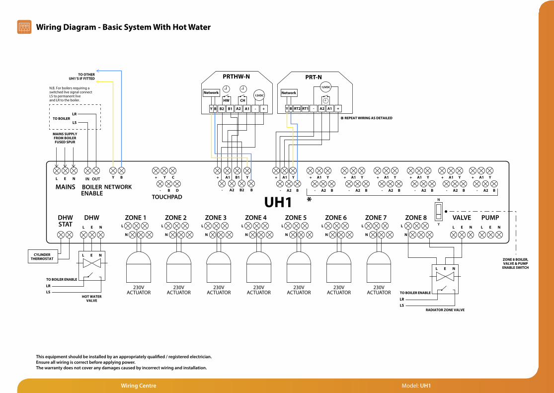
5
Model: UH1

Model: UH1
LL E N
L E N
L
N
E N
PUMPVALVEL E N
DHWDHWSTAT
MAINS NETWORK
TOUCHPAD
ZONE 8L
N
ZONE 7L
N
ZONE 6L
N
ZONE 5L
N
ZONE 4L
N
ZONE 3L
N
ZONE 2L
N
ZONE 1
CYLINDERTHERMOSTAT
HOT WATERVALVE
MAINS SUPPLYFROM BOILERFUSED SPUR
TO BOILER
TO OTHERUH1’S IF FITTED
230VACTUATOR
230VACTUATOR
230VACTUATOR
230VACTUATOR
230VACTUATOR
230VACTUATOR
230VACTUATOR
L E N
RADIATOR ZONE VALVE
L E N
Y B + A1 B1 Y
- A2 B2 B
+ A1 Y
- A2 B
+ A1 Y
- A2 B
+ Y C
- B D
+ A1 Y
- A2 B
+ A1 Y
- A2 B
+ A1 Y
- A2 B
+ A1 Y
- A2 B
+ A1 Y
- A2 B
REPEAT WIRING AS DETAILED
PRTHW-N
B2 B1 A2 A1 - +Y B
Network12VDC
CHHW
PRT-N
RT2 RT1 - A2 A1 +Y B
Network
12VDC
*
*
BASIC SYSTEM WITH HOT WATER
BOILERENABLE
IN OUT
This equipment should be installed by an appropriately quali�ed / registered electrician.Fully read the instructions for proper wiring before applying power.The warranty does not cover damage from improper wiring or installation.
Y
N
N.B. For boilers requiring a switched live signal connect LS to permanent live and LR to the boiler.
LS
LR
ZONE 8 BOILER,VALVE & PUMP
ENABLE SWITCH
TO BOILER ENABLE
LS
LR
TO BOILER ENABLE
LS
LR
Wiring Diagram - Basic System With Hot Water
Wiring Centre Model: UH1
This equipment should be installed by an appropriately qualified / registered electrician.Ensure all wiring is correct before applying power. The warranty does not cover any damages caused by incorrect wiring and installation.
LL E N
L E N
L
N
E N
PUMPVALVEL E N
DHWDHWSTAT
MAINS NETWORK
TOUCHPAD
ZONE 8L
N
ZONE 7L
N
ZONE 6L
N
ZONE 5L
N
ZONE 4L
N
ZONE 3L
N
ZONE 2L
N
ZONE 1
CYLINDERTHERMOSTAT
HOT WATERVALVE
MAINS SUPPLYFROM BOILERFUSED SPUR
TO BOILER
TO OTHERUH1’S IF FITTED
230VACTUATOR
230VACTUATOR
230VACTUATOR
230VACTUATOR
230VACTUATOR
230VACTUATOR
230VACTUATOR
L E N
TO BOILER ENABLE
RADIATOR ZONE VALVE
L E N
Y B
TOUCHPADNETMONITOR+
ROUTER
+ - Y B C D
+ A1 B1 Y
- A2 B2 B
+ A1 Y
- A2 B
+ A1 Y
- A2 B
+ Y C
- B D
+ A1 Y
- A2 B
+ A1 Y
- A2 B
+ A1 Y
- A2 B
+ A1 Y
- A2 B
+ A1 Y
- A2 B
Y
B
INTERNET
INTRANET
MAINS POWER SUPPLY
REPEAT WIRING AS DETAILED
N.B. If no TouchPad is �tted, the B & Y from the NetMonitor connect to B & Y on the UH1
PRTHW-N
B2 B1 A2 A1 - +Y B
Network12VDC
CHHW
PRT-N
RT2 RT1 - A2 A1 +Y B
Network
12VDC
*
*
UH1 WITH HOT WATER & RADIATOR CIRCUIT
BOILERENABLE
IN OUT
This equipment should be installed by an appropriately quali�ed / registered electrician.Fully read the instructions for proper wiring before applying power.The warranty does not cover damage from improper wiring or installation.
Y
ZONE 8 BOILER,VALVE & PUMP
ENABLE SWITCH
N
N.B. For boilers requiring a switched live signal connect LS to permanent live and LR to the boiler.
LS
LR
LS
LR
TO BOILER ENABLE
LS
LR
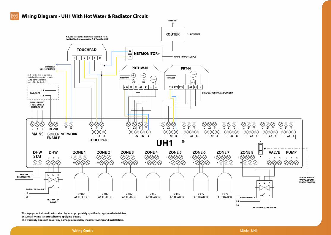
Wiring Diagram - UH1 With Hot Water & Radiator Circuit
Wiring Centre Model: UH1
This equipment should be installed by an appropriately qualified / registered electrician.Ensure all wiring is correct before applying power. The warranty does not cover any damages caused by incorrect wiring and installation.
Wiring Centre Model: UH1
L E N
L E N
DHWDHWSTAT
MAINS NETWORK
TOUCHPAD
L
N
ZONE 5L
N
ZONE 4L
N
ZONE 3L
N
ZONE 2L
N
ZONE 1
CYLINDERTHERMOSTAT
HOT WATERVALVE
MAINS SUPPLYFROM BOILERFUSED SPUR
TO BOILER
230VACTUATOR
230VACTUATOR
230VACTUATOR
230VACTUATOR
230VACTUATOR
L E N
Y B
TOUCHPADNETMONITOR+
ROUTER
+ - Y B C D
+ A1 B1 Y
- A2 B2 B
+ A1 Y
- A2 B
+ Y C
- B D
Y
B
INTERNET
INTRANET
MAINS POWER SUPPLY
REPEAT WIRING AS DETAILED
N.B. If no TouchPad is �tted, the B & Y from the NetMonitor connect to B & Y on the UH1
PRTHW-N
B2 B1 A2 A1 - +Y B
Network12VDC
CHHW
PRT-N
RT2 RT1 - A2 A1 +Y B
Network
12VDC
*
UH1 WITH HOT WATER & RADIATOR CIRCUIT
BOILERENABLE
IN OUT
N.B. For boilers requiring a switched live signal connect LS to permanent live and LR to the boiler.
LS
LR
L E N
L E N
DHWDHWSTAT
MAINS NETWORK
TOUCHPAD
L
N
ZONE 5L
N
ZONE 4L
N
ZONE 3L
N
ZONE 2L
N
ZONE 1
CYLINDERTHERMOSTAT
HOT WATERVALVE
MAINS SUPPLYFROM BOILERFUSED SPUR
230VACTUATOR
230VACTUATOR
230VACTUATOR
230VACTUATOR
230VACTUATOR
L E N
+ A1 B1 Y
- A2 B2 B
+ A1 Y
- A2 B
+ Y C
- B D
REPEAT WIRING AS DETAILED
PRTHW-N
B2 B1 A2 A1 - +Y B
Network12VDC
CHHW
PRT-N
RT2 RT1 - A2 A1 +Y B
Network
12VDC
*
BASIC SYSTEM WITH HOT WATER
BOILERENABLE
IN OUT
This equipment should be installed by an appropriately quali�ed / registered electrician.Fully read the instructions for proper wiring before applying power.The warranty does not cover damage from improper wiring or installation.
TO OTHERUH1’S IF FITTED
Y B
TO BOILER ENABLE
LSLR
TO BOILER ENABLE
LSLR
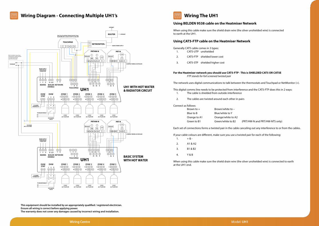
Wiring Diagram - Connecting Multiple UH1’s Wiring The UH1Using BELDEN 9538 cable on the Heatmiser Network
When using this cable make sure the shield drain wire (the silver unshielded wire) is connected to earth at the UH1.
Using CAT5-FTP cable on the Heatmiser Network
Generally CAT5 cable comes in 3 types:1. CAT5-UTP unshielded 2. CAT5-FTP shielded lower cost
3. CAT5-STP shielded higher cost
For the Heatmiser network you should use CAT5-FTP - This is SHIELDED CAT5 OR CAT5E FTP stands for foil screened twisted pair
The network uses digital communications to talk between the thermostats and Touchpad or NetMonitor (+).
This digital comms line needs to be protected from interference and the CAT5-FTP does this in 2 ways:1. The cable is shielded from outside interference
2. The cables are twisted around each other in pairs
Connect as follows: Brown to + Brown/white to – Blue to B Blue/white to Y Orange to A1 Orange/white to A2 Green to B1 Green/white to B2 (PRT/HW-N and PRT/HW-NTS only)
Each set of connections forms a twisted pair in the cable canceling out any interference to or from the cables.
If your cable colours are different, make sure you use a twisted pair for each of the following:1. + & -
2. A1 & A2
3. B1 & B2
4. Y & B
When using this cable make sure the shield drain wire (the silver unshielded wire) is connected to earth at the UH1 end.
This equipment should be installed by an appropriately qualified / registered electrician.Ensure all wiring is correct before applying power. The warranty does not cover any damages caused by incorrect wiring and installation.

Want More Information?Call our support team on: +44 (0)1254 669090Or view technical specifications directly on our website: www.heatmiser.com
PRT-N PRTHW-N Touchpad
UH1-W UH2 UH3
NetMonitor(+)
FAQ
Heating Professionals:Request a copy of our product installation guide containing detailed technical specifications for our complete product range:www.heatmiser.com/guide
Twitter: heatmiserukFacebook:facebook.com/thermostats
Products Commonly Used With UH1 Wiring Centre:
Other Heatmiser Wiring Centres:


