ABSTRACT: The impact of model uncertainty on the damage-prediction accuracy of a nondestructive damagedetection technique when applied to a model plate girder is assessed. First, a damage-detection algorithm tolocate and size damage from few mode shapes of structures is outlined. Next, locations and magnitudes ofdamage in the model plate girder are predicted by using the damage-detection algorithm. Finally, damageprediction accuracy for the model plate girder is estimated as a function of model uncertainties that are mostlikely or exist in the damage-detection procedure of the model plate girder. By applying the approach to themodel plate girder, it is observed that damage can be confidently located with a relatively small localizationerror and a relatively small false-negative (i.e., missing detection of true damage locations) error but a relativelylarge false-positive (i.e., prediction of locations that are not damaged) error. It is also observed that severityof damage can be estimated with a relatively large error.
THEORY OF NOD ALGORITHM
where <l>i = ith modal vector; and C system stiffness matrix. The contribution of the jth member to the ith modalstiffness, Kij' is given by the following:
where Cj = contribution of jth member to the system stiffnessmatrix. Then, the fraction of modal energy (i.e., the undamaged sensitivity) of ith mode and jth member is given by thefollowing:
(1)
(2)
K i = <prOt)i
The method described here yields information on the location and severity of damage directly from changes in modeshapes of structures. The appealing features of this methodinclude the following: (1) Only mode shapes are needed inthe analysis; (2) damage can be located and sized using fewmodes; (3) damage can be located and sized without solvinga system of equations; and (4) damage can be located andsized in structures containing many members.
Consider a linear, undamaged, skeletal structure with NEelements and N nodes. The ith modal stiffness of the arbitrarystructure is given by the following (Stubbs and Osegueda1990):
Fij = Ki/Ki (3)
Let the corresponding modal parameters in (1)-(3) associated with a subsequently damaged structure be characterizedby asterisks. Then for the damaged structure
the NDD algorithm to locate and size damage in structuresusing few modal responses of the structures; then we demonstrate the feasibility and practicality of the NDD algorithmby locating and sizing damage in a model plate girder; andfinally we assess the accuracy of the NDD results as a functionof model uncertainties for the model plate girder.
INTRODUCTION
During the past decade, many research studies have focused on the possibility of using the vibration characteristicsof structures as an indication of structural damage (Adamset al. 1978; Cawley and Adams 1979; O'Brien 1980; Crohasand Lepert 1982; Chondros and Dimarogonas 1982; Gudmunson 1982,1983). More recently, attempts have been madeto monitor structural integrity of bridges (Biswas et al. 1990;Flesch and Kernichler 1988) and to investigate the feasibilityof damage detection in large space structures using changesin modal parameters (Stubbs et al. 1992; Chen and Garba1988). Also, a few studies have investigated model uncertainty in structural systems (Vanmarcke et al. 1986; Beck andKatafygiotis 1991) and assessed the effect of model uncertainty on damage-detection accuracy in beams (Stubbs et al.1991). Despite these combined research efforts, there are stilloutstanding needs: e.g., to detect damage in structures withlimited modal information and to evaluate the damage in anenvironment of uncertainty due to modeling errors and modalresponse-measurement errors. Model uncertainty is definedhere as a lack of knowledge regarding the topology, geometry,material properties, and dynamic modal responses of thestructure. In this study, model uncertainty for nondestructivedamage detection encompasses such causes as (1) the uncertainty due to modeling errors in the choice of structure (orstructural member) types; (2) the uncertainty due to inaccurate measurements of geometric and material properties;and (3) the uncertainty due to measurement noises, errors,and incompleteness in dynamic modal responses.
The objective of this paper is to evaluate the impact ofmodel uncertainty on the accuracy of a nondestructive damage detection (NDD) technique when applied to a modelplate girder for which only few modal response parametersare available. We define accuracy as the degree of conformityof a measure to a true value. By relative impact we are referring to the size of the effect of model uncertainty as afunction of the various types of uncertainties. The objectiveis accomplished in the following three tasks. First, we outline
'Res. Assoc.. Mech. and Mat. Ctr., Dept. of Civ. Engrg., Texas A&MUniv., College Station, TX 77843.
'Assoc. Prof., Mech. and Mat. Ctr., Dept. of Civ. Engrg., TexasA&M Univ., College Station, TX.
The quantities Cj and Cj in (2) and (4) may be written asfollows:
(6a,b)
where Ej = a parameter representing the material stiffness
JOURNAL OF STRUCTURAL ENGINEERING / OCTOBER 1995/1409
J. Struct. Eng. 1995.121:1409-1417.
Dow
nloa
ded
from
asc
elib
rary
.org
by
SOU
TH
ER
N C
AL
IFO
RN
IA U
NIV
ER
SIT
Y o
n 04
/09/
14. C
opyr
ight
ASC
E. F
or p
erso
nal u
se o
nly;
all
righ
ts r
eser
ved.
90 in. ) I> in.
Cracks
's~:,...._9_.L._10_;-J~LlI-'1.7
Accelerometer
1~ 2 3I;: . .properties; and the matrix Cjo involves only geometric quantities (and possibly terms containing Poisson's ratio). Notethat Cjo can represent bending, torsional, axial, shear, or evenplate elements. In addition, the parameter E j is always thesame and is related to the effective modulus of elasticity ofthe element. Suppose we make the approximation that thefraction of modal energy is the same for both damaged andundamaged structures. Substituting (6) into (5) and rearranging, then a damage index I3j i of ith mode and jth member(and for NM vibrational modes, a damage index I3j of jthmember) is obtained by (Stubbs et al. 1992)
Choose HI when Zj 2: K; Choose H o when Zj < K (9a,b)
in which K = a number that reflects the level of significanceof the test (e.g., if K = 2, then the confidence level is 97.7%).
We estimate the severity of damage in the jth member asfollows. Let the fractional change in the stiffness of the jthmember be given by the severity estimator, a j ; then
where I3j 2: 0 and damage is indicated at the jth member ifI3j > 1. Kim and Stubbs (1995) provide a more detailed explanation and discussion of this approximation.
The predicted location j is classified into one of two groupsundamaged and damaged locations. First, the values of theindicator I3j (j = 1,2,3, ... ,NE) are normalized accordingto the rule
Stage 3
(b)
Stage 2SIlIge 1
(e)
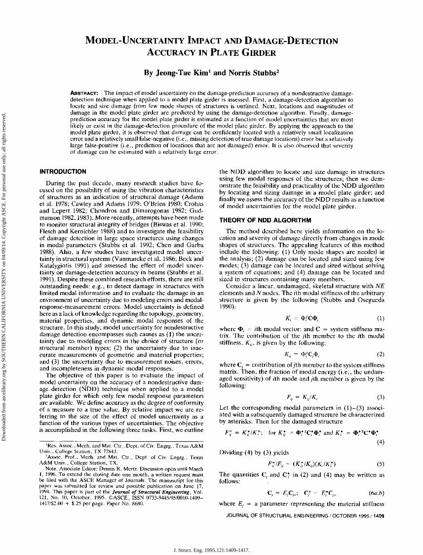
FIG. 1. Model Plate Girder: (a) Schematic; (b) Bridge-Girder Details; (c) Crack Increments in Girder Section
TABLE 1. Resonant Frequencies of Model Plate Girder
in which ~ and (J13 = mean and the standard deviation ofthe collection of I3j values, respectively. Next, the member isassigned to damage class via a statistical-pattern-recognitiontechnique that utilizes hypothesis testing [e.g., Gibson andMelsa (1975)]. The null hypothesis (i.e., H o) is the structureis not damaged at the jth location. The alternate hypothesis(i.e., HI) is the structure is damaged at the jth location. Wedefine the decision rule as follows [see Gibson and Melsa(1975) for details]:
DAMAGE DETECTION IN MODEL PLATE GIRDER
The test structure, a two-span aluminum model plate girder, is shown in Fig. 1. Mazurek and DeWolf (1990) conducted controlled laboratory experiments on the structure tomeasure changes in modal responses caused by structural degradation. The model bridge consisted of plates and angleshapes, bolted together to form two I-section girders. Thegirders were joined together by cross ties on the top and thebottom chords, as shown in Fig. 1, forcing the structure toact essentially as a box girder. The structure had three supports: a pin support 0.15 m (6 in.) from the left edge, a rollersupport at the middle, and another roller support 0.15 m fromthe right edge. The following procedure was used to locateand size damage in the structure: (1) The modal responsesof the structure were aquired; (2) a damage-detection modelof the structure was selected; and (3) damage localization andseverity estimation in the structure was performed using theNDD theory. Here, a damage-detection model (DDM) is
1410/ JOURNAL OF STRUCTURAL ENGINEERING / OCTOBER 1995
""1J
~a.~ --{l.5
o"1J -1o
:::li
FIG. 2. First Bending Mode Shapes for Model Plate Girder
defined as a mathematical representation of a structure withdegrees of freedom limited to sensor readings.
Eleven accelerometers were placed along the deck of themodel bridge. Ambient forces from lightweight traffic cartsexcited the structure. The extracted modal responses of thestructure included predamage and postdamage mode shapesof the first bending mode and resonant frequencies of thefirst three bending modes. A known damage was inflicted in
(10)
(lla,b)
£t = £j(1 + a)
Combining (7) and (10) yields
J. Struct. Eng. 1995.121:1409-1417.
Dow
nloa
ded
from
asc
elib
rary
.org
by
SOU
TH
ER
N C
AL
IFO
RN
IA U
NIV
ER
SIT
Y o
n 04
/09/
14. C
opyr
ight
ASC
E. F
or p
erso
nal u
se o
nly;
all
righ
ts r
eser
ved.
the structure by cracking the girder at a location 1.02 m (40in., to the left of the right support). The crack (i.e., theinflicted damage) was placed on the right web (Fig. 1). Thecrack was developed further by sequentially reducing the second moment of area at the damaged location to about 81 %(stage 1 in Fig. 1), 68% (stage 2 in Fig. 1), and 67% (Stage3 in Fig. 1) of the original cross section (note that thesedamage stages correspond to reducing the bending stiffnessat the damaged section by 19%, 32%, and 33%). The measured resonant frequencies are listed in Table 1 and the extracted mode shapes for the first mode are shown in Fig. 2.Note that these mode shapes were obtained by digitizing theoriginal mode shapes presented by Mazurek and DeWolf(1990). Note also that we use the data from the 11 accelerometers only because these data were provided in the referenced work. We do not imply that such an arrangement ofsensors is necessary or sufficient to perform damage localization using the present method. A more detailed discussionon the placement of sensors for damage detection is a subjectof future study.
As a DDM of the structure, we selected an Euler-Bernoullibeam model because (1) the structure consists of a box girderthat can be modeled as a beam; and (2) the extracted modaldata provide information to model a one-dimensional structure. As schematized in Fig. 1, the DDM consisted of 50beam elements of equal size. Now, the fraction of modalenergy for the Euler-Bernoulli beam model (i.e., the equivalent expression for the right-hand side of (3) of element kand mode i between two locations (Xk' Xk + LlXk) is given bythe following:
Lq+~ LL
F;k = EU<I>7(x)F dxIK" for K, = EU<I>7(x)F dxXI.: 0
(12)
The elastic modulus and the second moment of area aboutz-axis for the 50 uniform elements were estimated, respectively, as follows: E = 70 Gpa (10 x 1()6 psi) and /z = 7.23X 10- 7 m4 (1.737 in. 4
). Next, the curvatures of the modeshapes were generated at the 51 nodes of the DDM (notethat each mode shape shown in Fig. 2 contained only 11 sensorreadings). The curvatures were obtained as follows: (1) modalamplitudes corresponding to nodes 1 to 51 were estimated byinterpolating, using cubic-spline functions, the mode shapesshown in Fig. 2; (2) a modal displacement function, w(x),was generated for the entire structure using third-order interpolation functions; and (3) the curvatures [i.e., <I>"(x)] weredetermined at the 51 nodes.
We located and estimated severity of damage in the structure for the three damage stages described previously. First,as the input to the DDM, we used only the predamage andpostdamage mode shapes of the first bending mode. Second,we computed the damage index [given by (7)] of the EulerBernoulli beam model [for which the fraction of modal energyis given by (12)]. Third, we decided potential damage locations by setting the damage localization criterion for (8) asfollows: (1) select H o (i.e., no damage exists at member i) ifZ; < 2; and (2) select the alternate HI if Z; ~ 2. This criterioncorresponds to a one-tailed test at a significance level of 0.023(97.7% confidence level). The damage-localization results forthe three damage stages are shown in Fig. 3. For each predicted damage location, we estimated severity of damage byusing (11). The estimated severities of damage are listed inTable 2. A negative value in Table 2 represents the reductionin stiffness.
Finally, the results of the damage prediction of the structureis shown in Fig. 3 and listed in Table 2. Note that at leastfour results on the damage prediction of the structure can beidentified. First, for all levels of damage (i.e., stage 1 to stage
3), damage is correctly predicted at the actual damage location (i.e., element 39). Second, damage is predicted in eight(three for stage 1, three for stage 2, and two for stage 3) falsepositive locations (i.e., eight additional locations in which nodamage is inflicted). Note that the locations of false positiveare in the vicinity of element 39. Third, the precision of thedamage localization increases as the level of the inflicted damage increases. Finally, the predicted severity-estimation results consistently overestimate the inflicted damage.
UNCERTAINTY ASSESSMENT OF DAMAGEPREDICTION ACCURACY
Our objective here is to assess the accuracy of damageprediction in the plate girder as a function of various modeluncertainties in the DDM of the structure. To accomplishthis objective, we evaluate the accuracy of the damage localization and severity estimation for the structure analyzedin the later section. In this study, the uncertainty assessmentis limited to tests on a theoretical model of the structure. Such
JOURNAL OF STRUCTURAL ENGINEERING / OCTOBER 1995/1411
J. Struct. Eng. 1995.121:1409-1417.
Dow
nloa
ded
from
asc
elib
rary
.org
by
SOU
TH
ER
N C
AL
IFO
RN
IA U
NIV
ER
SIT
Y o
n 04
/09/
14. C
opyr
ight
ASC
E. F
or p
erso
nal u
se o
nly;
all
righ
ts r
eser
ved.
FIG. 5. Schematic of FE Model of Model Plate Girder
~ 111111111111111111111111f.11111111111111111llIlIll1l-Element I Element 25 Element 50 I
IE: 50@36in. _ 180 in. ~
TABLE 3. Sensitivity Matrix to Fine-Tune FE Model
(spring 1)]; and member type 3 [the middle axial spring (Spring2)]. Initial values for the geometric properties of the FE modelwere estimated as follows: (1) for member type I, A = 1.05X 10- 3 m2 (1.625 in. 2
), the second moment of area withrespect to z-axis (shown in Fig. 1) I z = 7.23 X 10- 7 m4 (1.737in. 4
), and the second moment of area with respect to y-axis(shown in Fig. 1) I y = 9.59 X 10- 2 m4 (3.990 in. 4
); and (2)for member types 2 and 3, A = 6.45 x 10-;; m2 (0.1 in. 2)and Iv = Iz = O. Material properties of the FE model wereassigned as: (1) the elastic modulus E = 70 Gpa (10 x 10°psi); (2) Poisson's ratio v = 0.33; and (3) the linear massdensity p = 2,710 kg/m' (2.537 x 10 -4 lb· s2/in.4). The stiffness parameters of the FE model selected to be fine-tunedwere (1) the stiffness matrix of a three-dimensional frameelement [see Craig (1981) for details] for member type 1; and(2) the axial rigidity (EA) for member types 2 and 3.
Suppose that ki = unknown stiffness of the ith memberof the structure for which three undamaged frequencies areknown (see Table 1); and ki = known stiffness of the ithmember of the FE model for which the corresponding threeundamaged frequencies are known. Then the fractional stiffness difference, ai' of the ith member in the two system arerelated according to the following equation:
where a = a 3 x 1 matrix containing the fractional changesin stiffnesses between the FE model and the structure; Z =a 3 x 1 matrix containing the fractional changes in eigenvalues between the FE model and the values measured onthe actual structure; and F = a 3 x 3 sensitivity matrixrelating the fractional changes in stiffnesses to the fractionalchanges in eigenvalues of the FE model. The F matrix isnumerically determined as follows: (1) Introduce a knownseverity of damage ak at the kth member of the initial FEmodel and compute three damaged eigenvalues; (2) computethe fractional changes in eigenvalues, Z, between the initialFE model and the FE model damaged at the kth member;(3) compute the components of the kth column of the F matrixby dividing Z by ak; and (4) generate the 3 x 3 F matrix byrepeating steps 1-3 with new damage scenarios up to threemembers. The F matrix of the FE model of the model plate
The fractional stiffness changes of the three members may beobtained using the following equation (Stubbs and Osegueda1990):
ICOMPONENT 1I Se1ection of Rea1 Stru<:ture
-VICOMPONENT 2
~~
IldentifieatiOD of MDdaI R<spoDseofRea1 Stru<:IuR:
'"COMPONENTS ICOMPONENT 3 I
l SeIec:tiOD ofDDM ofRea1 Struetur< ISelectiOD of Model J,Uncertainty Type
ICOMPONENT 4 IiD DDM ofRea1 SInJcture H Damage Localizatioo
Iand Severity Estimation
ICOMPONENT 6IDevelopmeol of 'fhcorotical Model
'"ICOMPONENT 7
ICOMPONENT 9Identification of MDdaI ResponseofThoorelical Model
Simulation of1,Model Uncertainty
ICOMPONENT 8 I.SelectiOD ofDDM ofThooretical Model I'
~OMPONENT 11 IQuantification of 1,Model Uncertainty ICOMPONENT 10 I-----r--- Damage Prediction in Theoretical Model
COMPONENT 13 '"Estimation of ICOMPONENT 12
IModel Uncertainty V. I QuantifieatiOD ofDamage PredictionNDD Accuracy ACCUIllCY of tile Theoretical Model
I1,
ICOMPONENT 14 r=-Assigrunent of NDD Accuracy LevelID Rea1 Struetur<
FIG. 4. Uncertainty Assessment Procedure
an approach is justified because, as will be shown, the theoretical model utilized here is a realistic, mathematical representation of the structure. Localization and severity-estimation accuracy are accomplished by following the procedureschematized in Fig. 4. The assessment procedure of Fig. 4 isaccomplished in eight major steps. In step 1, components 14, we locate and size damage in the model plate girder. Notethat this step was performed in the previous section. In step2, component 6, we identify a theoretical model of the structure by using a system identification method. In step 3, components 5 and 9, we select types of model uncertainty thatmay exist in the damage-detection procedure of the structureand further incorporate the selected model uncertainties intothe theoretical model of the structure. In step 4, components7,8, and 10, the proposed NDD algorithm is used to localizeand estimate severity of damage inflicted in the theoreticalmodel. Here, damage-detection exercises are performed byusing either an exact DDM (an uncertainty-free DDM) oruncertainty-inflicted DDMs. In step 5, component 11, wequantify model uncertainties simulated in the theoretical model.In step 6, component 12, we quantify damage-prediction accuracy of the theoretical model. In step 7, component 13, weestimate the accuracy of damage localization and severityestimation results of the theoretical model as a function ofmodel uncertainties simulated in the theoretical model. Finally, in step 8, component 14, we assess the damage-prediction accuracy of the real structure. These steps are elaborated on as follows.
Identification of Theoretical Model
To identify a realistic theoretical model of the model structure, we fine-tuned a three-dimensional frame finite-element(FE) model (as an initial guess) using a system-identificationconcept that combines experimental and theoretical responses of the structure. As shown in Fig. 5, the FE modelconsisted of three member types: member type 1 (the 50equally sized, three-dimensional frame elements that modelthe plate girder); member type 2 [the two outside axial springs
14121 JOURNAL OF STRUCTURAL ENGINEERING I OCTOBER 1995
J. Struct. Eng. 1995.121:1409-1417.
Dow
nloa
ded
from
asc
elib
rary
.org
by
SOU
TH
ER
N C
AL
IFO
RN
IA U
NIV
ER
SIT
Y o
n 04
/09/
14. C
opyr
ight
ASC
E. F
or p
erso
nal u
se o
nly;
all
righ
ts r
eser
ved.
girder is listed in Table 3. For a given mode, each sensitivityrepresents the fraction of modal energy of that mode storedin the particular member type.
Finally, the theoretical model was identified in three steps.First, the fractional changes in eigenvalues between the FEmodel and the target structure were computed. Next, the FEmodel was fine-tuned by first solving (14) to estimate stiffnesschanges (i.e., NE x 1 matrix a) and then solving (13) toupdate the stiffness parameters of the FE model. Finally, thewhole procedure was repeated until Z or a approached zero.The results, using three frequencies and 10 iterations, arelisted in Table 4. Note that after 10 iterations, the identifiedfrequencies are within 1% of the target values. Based on thisresult, the FE model of the tenth iteration was selected asthe theoretical model.
Simulation of Model Uncertainty in Theoretical Model
In this study, we selected three model-uncertainty typesthat may exist in the DDM of the model plate girder. Thereis uncertainty involved in the selection of the DDM, becausethe Euler-Bernoulli beam model used for the damage prediction of the structure only approximates the true mechanicalresponse of the structure. We could have selected a shearbeam model, a Timoshenko beam model, or even a detailed3-D finite element model of the structure. Thus the uncertainty associated with model selection becomes our first concern. As the second type, we selected uncertainty in the stiffness parameters because the true stiffness parameters of thestructure are unknown. As the third type, we selected uncertainty in the mode shapes because the modal amplitudesused here for the damage prediction of the structure cancontain (1) errors in the originally derived mode shapes (Mazurek and DeWolf 1990); (2) errors resulting from digitizingthe original mode shapes; and (3) errors resulting from theuse of cubic-spline interpolations of the digitized mode shapes.
Here we describe the simulation of the three model-uncertainty types identified previously. The uncertainty in theDDM selection is systematic [i.e., it measures the degree towhich an event occurs (Kosko 1992)]. This uncertainty wassimulated by varying the choice of DDM. The following twomodels were considered: (1) the 3-D frame FE model (i.e.,the theoretical model itself) as an exact DDM; and (2) theEuler-Bernoulli beam model as an uncertainty-inflicted DDM.Note that element sensitivities of the FE model are given by(3) (which represents the true mechanical response of thetheoretical model). Note also that element sensitivities of theEuler-Bernoulli beam model are given by (12) (which approximates the true mechanical response of the theoreticalmodel).
The uncertainty in the stiffness parameters is random (Yanmarcke et al. 1986). As shown in Fig. 5, the FE model issubdivided into 50 elements. Although the stiffness of eachelement is constant, the distribution of the element stiffnessesis assumed to follow a lognormal distribution. Three differentlevels of uncertainty in the stiffness parameters were simulated as follows: (1) An FE model corresponding to a distribution of elastic moduli with a mean of 70 Gpa and with acoefficient of variation (COY) equal to 0.1; (2) the FE model
with COY = 0.3; and (3) the FE model with COY = 0.5.A random number generator was used to obtain the corresponding elastic moduli for the distributions.
The uncertainty in the mode shapes is also random. In thisexample, each mode shape is defined by a 51 x 1 matrixwhose elements represent the vertical degrees of freedom atnodes of the FE model. Note that only a single mode (in thiscase, the first bending mode) was used for the damage detection in the structure. The amplitude of mode i at locationj [i.e., <j>;(x)] is treated as a random variable with a meanE[<j>;(x)] and a COY. Five different levels of uncertainty inthe mode shape of the first bending mode (see Fig. 2) weresimulated with coefficients of variation equal to 0.01, 0.05,0.1, 0.2, and 0.3. Monte Carlo simulations were employed togenerate the random mode shapes.
Damage Localization and Severity Estimation inTheoretical Model
For each model uncertainty simulated in the theoreticalmodel, damage localization and severity estimation in thetheoretical model were performed in three steps. First, wegenerated predamage and postdamage mode shapes for thetheoretical model; second, we selected damage-detectionmodels for the theoretical model; and third, we performeddamage localization and severity estimation in the theoreticalmodel.
The predamage and postdamage modal parameters for thetheoretical model were generated numerically using the software package ABAQUS (1992). Here, nine damage caseswere investigated, as summarized in Table 5. In all cases,damage was simulated in the structure by reducing the secondmoment of area of the appropriate members of the FE modelshown in Fig. 5. The first six damage cases were limited tothe theoretical model damaged at a single location, and theremaining three cases considered damage inflicted at two locations. Note that these damage cases form the sample of ourpopulation for future statistical analyses. The predamage andpostdamage frequencies of the first three modes are listed inTable 6. Typical numerically generated mode shapes of thefirst three modes are shown in Fig. 6.
In step 2, a DDM was selected for each model-uncertaintytype simulated in the theoretical model. For the uncertaintyin the DDM selection, we selected the Euler-Bernoulli beammodel [represented by (12)] as the DDM of the theoreticalmodel. For the uncertainty in the stiffness parameter, weselected the FE model as the DDM. For the uncertainty inthe mode shape, we selected the Euler-Bernoulli beam modelas the DDM.
In step 3, locations and magnitudes of damage in the theoretical model were predicted for each model-uncertainty casesimulated in the theoretical model. First, we selected predamage and postdamage mode shapes of the theoretical model.We used only a single mode (i.e., mode 1 in Fig. 6) in thisdamage-detection exercise. Second, we computed the damage-localization indicator [given by (7)] of the selected DDMfor each model-uncertainty case. Third, we localized potentialdamage using the same criteria as those in the damage-prediction exercise for the model plate girder. Finally, we esti-
TABLE 4. Values of Frequencies (Hz) for 10 Iterations
Eq. (15) quantifies the difference in orientation between Uand V, without regard to scaling difficulties arising from choiceof numerical distance units. If SAC(U, V) = 0, then thevectors U and V are perfectly correlated (no uncertainty exists). If SAC(U, V) > 0, then U and V become linearly unassociated with each other.
We quantified model uncertainty in the theoretical modelof the structure by implementing the SAC measure of (15)to each uncertainty type simulated in the theoretical model.Using only the first bending mode, the predamage modalsensitivities of (15) (i.e., U ERNE) were obtained from the3-D frame FE model (i.e., the exact DDM). Also, for eachsimulated uncertainty, the postdamage modal sensitivities of(15) (i.e., VERNE) were obtained from each uncertaintyinflicted DDM. Results obtained for the three model uncertainty types are listed in Table 8. Three major results follow.First, SAC is very small when the Euler-Bernoulli beam modelis selected as a DDM of the theoretical model. Second, theSA C measure increases when the uncertainty in the stiffnessparameters increases. Third, SAC increases significantly evenwhen the uncertainty in the mode shape increases slightly.
123456789
49
14192439
4, 299, 34
14,39
-10-10-10-10-10-10~ 10, -10~ 10, -10-10, -10
cos(U, V) = UVT/IIUIIIIVII (16)
0.8
0.6QJ
~ 0.4
a.. 0.2
~ o-F-----"J'-----It-------,/r--------::J
"0 -0.2
15 -0.4
~ -0.6
-0.8
-1 .1,..,-~'I":'_c~~~~~~~~~__,_::;:>_
11 16 21 26 31 36 41 46 51
Node Number
1-- Mode 1 --e- Mode 2 ---- ModeiJFIG. 6. Mode Shapes of Theoretical Model
mated damage severity at each predicted damage location byusing (11). For example, Table 7 shows damage-localizationand severity-estimation results for two models: the exact DDM(i.e., no uncertainty exists) and the Euler-Bernoulli beammodel (i.e., uncertainty in DDM selection exists).
Quantification of Model Uncertainty inTheoretical Model
To quantify the simulated model uncertainties, which areeither systematic or random, we selected a sensitivity assurance criterion (SAC) based on a metrical measure of modalenergy changes (Kosko 1992b). Let RNE represent·a space oforder NE. Consider two sampled patterns U and V such thatU ERNE and VERNE. The elements of U are the predamagemodal sensitivities given by (3). The elements of V are postdamage modal sensitivities either given by (3) (in the case ofuncertainty in the stiffness parameter) or by (12) (in the caseof uncertainty in the DDM selection or uncertainty in themode shape). Then the uncertainty measure, SAC, is definedas follows:
1414/ JOURNAL OF STRUCTURAL ENGINEERING / OCTOBER 1995
Quantification of Damage-Prediction Accuracy ofTheoretical Model
The accuracy of damage-prediction results of the theoretical model was quantified by measuring both metrical errors[see e.g., Kosko (1992b)] and the common errors used in testsof hypotheses [i.e., type I and type II errors (Devore 1987)].As the first NOD accuracy measure, we selected a meanlocalization error (MLE) defined as follows:
1 N
MLE(t, f) = N ;?, Ix: - x11/L; for 0 $ MLE(t, f) $ 1 (17)
where N = number of damage cases; x~ = a true locationof ith damage case; xf = a false location of ith damage case;and L = a characteristic distance (e.g., a span of a bridge).The MLE measure is an indicator of the localization accuracyof the method. If MLE = 0, then there is no error. If MLE= 1, then the damage localization is a maximum.
As the second NOD accuracy measure, we selected a detection missing error (DME) measure defined as follows:
1 N
DME(t, f) = - L E{; for 0 $ DME(t, f) $ 1 (18)NT;~,
in which NT = number of true damage locations; and d =a type I localization error (i.e., d = 0 if ith damage locationis predicted or E ~ = 1 if otherwise). If D ME = 0, then alltrue damage locations are correctly predicted.
As the third NOD accuracy measure, we selected a falsealarm error (FAE), which is defined as follows:
in which NF = number of predicted locations; Ell is a typeII localization error (i.e., Ell = 0 if ith predicted location istrue or EV = 1 if otherwise). If FAE(t, f) = 0, then allpredicted locations are truly damaged locations.
As the last NOD accuracy measure, we selected a meansizing error (MSE), which is defined as follows:
J. Struct. Eng. 1995.121:1409-1417.
Dow
nloa
ded
from
asc
elib
rary
.org
by
SOU
TH
ER
N C
AL
IFO
RN
IA U
NIV
ER
SIT
Y o
n 04
/09/
14. C
opyr
ight
ASC
E. F
or p
erso
nal u
se o
nly;
all
righ
ts r
eser
ved.
TABLE 7. Damage Prediction Results of Theoretical Model
Predicted Damage UsingSimulated Damage Predicted Damage Using Exact DDM Euler-Bernoulli Beam Model
Magnitude(s) Magnitude(s) Magnitude(s)Damage case Location(s) (%) Location(s) (%) Location(s) (%)
where a{ = an estimated severity and ai = a true damageseverity of ith predicted location. The MSE measure is anindicator of the damage-magnitude predicting capacity of theNDD method. If MSE(t, f) is close to 0, then the severityestimation error is close to O.
For each model-uncertainty case, we implemented the fourNDD accuracy measures of (17)-(20) to the damage-localization and severity-estimation results of the theoretical model(e.g., such as listed in Table 7) and obtained the NDD accuracy results listed in Table 9. From Table 9, three majorresults on the quantification of the NDD accuracy are observed. First, due to the uncertainty in the choice of the EulerBernoulli beam model as a DDM, the accuracy measureschange as follows: (1) an MLE of 0.03 indicates that damageunder the given conditions can be predicted in 3% of thebridge length; (2) a DME of 0.083 indicates that 11 out of12 true damage locations under the given conditions can bepredicted; (3) an FAE of 0.25 indicates that one of four predicted locations can be a false positive; and (4) an MSE of0.23 means that the estimated severities of damage show anaverage 23% error. Second, MLE, DME, FAE, and MSEdo not change with the uncertainty in the stiffness parameter.This behavior occurs because the NDD theory used in thisstudy is independent of material properties. Third, when theuncertainty in the mode shape increases, the accuracy measures show that (1) MLE, DME, and MSEvalues consistentlyincrease; and (2) FAE increases up to COY = 0.2%, thendecreases. Note that the FAE measure is high even in thecase of the FE model (i.e., the uncertainty-free DDM). Thisbehavior may be result from either an insufficient number ofmodes considt;red (note that only a single mode was used inthe damage prediction of 50 elements) or the approximationin the NDD algorithm.
The accuracy of the damage-localization and severity-estimation results of the theoretical model can be estimated asa function of model uncertainties simulated in the theoreticalmodel of the model plate girder. This objective is accomplished in two steps: first, we select model uncertainty typesthat have relatively strong impacts on the damage-predictionaccuracy in the theoretical model; and next, we quantify therelationships between the NDD accuracy measures and themodel-uncertainty measure for the uncertainty types that haverelatively strong impacts.
From Tables 8 and 9, the four major results on the uncertainty assessment are observed as follows: (1) The uncertaintyin the DDM selection has a relatively weak influence on MLEand DME and a relatively strong influence on FAE and MSE;(2) the uncertainty in the stiffness parameter has no influenceon MLE, DME, FAE, and MSE; and (3) the uncertainty inthe mode shape has a relatively strong influence on MLE,DME, and MSE, but a relatively weak influence on FAE.From this comparison, we select two uncertainty types thathave relatively stronger impacts on the NDD accuracy: theuncertainty in the DDM selection and the uncertainty in themode shape.
The model-uncertainty measure (i.e., SAC measure) forthese selected uncertainty types are obtained from Table 8.Also, the NDD accuracy measures (i.e., MLE, DME, FAE,and MSE measures) for these selected uncertainty types areobtained from Table 9. The relationships between the NDDaccuracy measures and the model uncertainty measure for themodel uncertainties of larger impacts are shown in Fig. 7.
Estimation of NOD Accuracy Level ofModel Plate Girder
The NDD accuracy of the model plate girder is estimatedas a function of model uncertainty in the structure in twoparts: first, model uncertainty in the structure is quantified;and next, the NDD accuracy level is assigned to the structure.We quantify model uncertainty in the real structure by usingthe model uncertainty measure [given by (15)]. Again, onlythe first bending mode is used in the procedure. The predamage modal sensitivities of (15) (i.e., U ERNE) are obtained from the 3-D frame FE model (i.e., the exact DDMof the theoretical model). The postdamage modal sensitivitiesof (15) (i.e., VERNE) are obtained from the DDM of themodel plate girder [i.e., the approximate Euler-Bernoulli beammodel (given by (12) used to detect damage in the modelplate girder]. From (15), we obtain a SAC of 0.098.
Next, the model uncertainty measure of the structure, SAC= 0.098, is evaluated using Fig. 7. Four major results re-
JOURNAL OF STRUCTURAL ENGINEERING / OCTOBER 1995/1415
J. Struct. Eng. 1995.121:1409-1417.
Dow
nloa
ded
from
asc
elib
rary
.org
by
SOU
TH
ER
N C
AL
IFO
RN
IA U
NIV
ER
SIT
Y o
n 04
/09/
14. C
opyr
ight
ASC
E. F
or p
erso
nal u
se o
nly;
all
righ
ts r
eser
ved.
TABLE 9. Quantification of NOD Accuracy of Theoretical Model
Site of uncertainty Simulated uncertainty MLE DME FAE MSE(1 ) (2) (3) (4) (5) (6)
FIG. 8. Illustration of MLE Value (MLE = 0.13) to Damage-Prediction Results for Damage Stage 1 of Model Plate Girder (SeeFig. 3)
ABAQUS user manual. (1992). Hibbitt, Karlsson & Sorensen, Inc.Adams, R. D., Cawley, P., Pye, C. J., and Stone, B. J. (1978). "A
vibration technique for non-destructively assessing the integrity ofstructures." 1. Mech. Engrg. Sci., 20, 93-100.
Beck, J. L., and Katafygiotis, L. S. (1991). "Updating of a model andits uncertainties utilizing dynamic test data." Computational stochasticmechanics, P. D. Spanos and C. A. Brebbia, eds., Elsevier AppliedScience, London, England, 125-135.
Biswas, M., Pandey, A. K., and Samman, M. M. (1990). "Modal technology for damage detection of bridges." NATO Advanced Res. Workshop on Bridge Evaluation, Repair and Rehabilitation, A. Nowak, ed.,Kluwer Academic Publishers, Boston. Mass., 161-174.
APPENDIX I. REFERENCES
The objective of this paper was to evaluate the impact ofmodel uncertainty on the accuracy of a nondestructive damage detection (NOD) technique when applied to a modelplate girder for which only few modal response parametersare available. This objective was achieved in three parts. First,the damage-detection algorithm to locate and size damagefrom changes in few mode shapes of structures was summarized. Next, the damage-detection algorithm was used to predict damage locations and damage severities in the modelplate girder for which only information on a single mode wasavailable. Finally, the accuracy of the damage-detection results for the model plate girder was assessed as a function ofmodel uncertainties.
By applying the approach to the model plate girder, weobtained the following relationships between model uncertainty and the NOD accuracy: (1) The uncertainty introducedby selecting the Euler-Bernoulli beam model as the damagedetection model had a relatively weak influence on the damage-localization error and the false-negative (i.e., missing detection of true damage locations) error, but the model selection had a relatively strong influence on the false-positive(i.e., prediction of locations that are not damaged) error andthe severity estimation error; (2) the uncertainty in the modeshapes as the input to the damage-detection model had arelatively strong influence on the damage-localization error,the false-negative error, the false-positive error, and the severity-estimation error; and (3) the uncertainty in the stiffnessparameters had no influence on the NOD accuracy.
For the plate-girder structure analyzed here, the evaluationof the impact of model uncertainty on the accuracy of thedamage-detection technique proposed here can be summarized as follows: (1) Damage can be confidently located towithin a fraction of 0.13 of the length of the span; (2) themagnitude of damage can be evaluated with a severity-estimation error of about 24%; (3) seven of 10 predicted locationscould be false positive; and (4) four of 10 damage locationscould be false-negative. These parameters will change as afunction of the quality and amount of modal informationavailable as well as modifications in the damage-detectionalgorithm.
'rAE
/DME;;,;t.1SE
"t.1LE
oa
VI
~ 0.8:lVIo.,
:::. 0.6>.uo
30.4 iu«g 0.2z
I'-,------,-'-~,-'-,--, --.,..--,----J
0.1 0.2 0.3 0.4 0.5 0.6
Model Uncertainty Measure (SAC)
FIG. 7. NOD Accuracy as Function of Model Uncertainty in Theoretical Model
Accelerometer 18 in.
'>., ~3
garding the NOD accuracy of the proposed real structurefollow. First, the MLE measure is about 0.13, which meansthat damage in the structure under the given conditions canbe localized to within 0.13 length of the bridge span (see Fig.8). Note that all predicted locations of the model plate girder,as shown in Fig. 3, are in the vicinity of the actual damagelocation. Second, the DME measure is about 0.4, which meansthat six of 10 damage locations in the structure under thegiven conditions can be predicted correctly. Note that damageis correctly predicted in the structure, as shown in Fig. 3.Third, the FAE measure is about 0.7, which ~ans that sevenof 10 predicted locations in the structure can be false positive.Note that damage is predicted in two or three false-positivelocations in the structure, as shown in Fig. 3. Note also thatthe false locations are adjacent to the actual damage location.These locations may in fact be effectively damaged, becausethe strain energy in adjacent members is also reduced. Fourth,the MSE measure is about 0.24, which means that damageseverity in the structure can be evaluated with a severity estimation error of 24%. As listed in Table 2, the predictedseverity-estimation results consistently overestimate the inflicted damage in the structure.
14161 JOURNAL OF STRUCTURAL ENGINEERING / OCTOBER 1995
J. Struct. Eng. 1995.121:1409-1417.
Dow
nloa
ded
from
asc
elib
rary
.org
by
SOU
TH
ER
N C
AL
IFO
RN
IA U
NIV
ER
SIT
Y o
n 04
/09/
14. C
opyr
ight
ASC
E. F
or p
erso
nal u
se o
nly;
all
righ
ts r
eser
ved.
Cawley, P., and Adams, R. D. (1979). "The location of defects in structures from measurements of natural frequencies." J. Strain Anal.,14(2),49-57.
Chen, J., and Garba, J. A. (1988). "On-orbit damage assessment forlarge space structures." AIAA J., 26(9), 1119-1126.
Chondros, T G., and Dimarogonas, A. D. (1980). "Identification ofcracks in welded joints of complex structures." J. Sound and Vibration,69(4),531-538.
Craig, R. R. (1981). Structural dynamics-an application to computermethods, John Wiley & Sons, Inc., New York, N.Y.
Crohas, H., and Lepert, P. (1982). "Damage-detection monitoring methodfor offshore platforms is field-tested." Oil and Gas J., 94-103.
Devore, J. L. (1987). Probability and statistics for engineering and thesciences. Brooks/Core Pub!. Co.
Flesch, R. G., and Kernichler, K. (1988). "Bridge inspection by dynamictests and calculations dynamic investigations of Lavent Bridge." Workshop on Struct. Safety Evaluation Based on System Identification Approaches, H. G. Natke and J. T. P. Yao, eds., Vieweg & Sons, Lambrecht/Pfalz, Germany, 433-459.
Gibson, J. D., and Melsa, J. L. (1975). Introduction to nonparametricdetection with applications. Academic Press, New York, N.Y.
Gudmunson, P. (1982). "Eigenfrequency changes of structures due tocracks, notches or other geometrical changes." J. Mech. of Phys. andSolids, 30(5), 339-353.
Gudmunson, P. (1983). "The dynamic behavior of slender structureswith cross-sectional cracks." 1. Mech. of Phys. and Solids, 31(4),329345.
Kim, J. T, and Stubbs, N. (1995). "Damage detection in offshore jacketstructures from limited modal information." Int. J. Offshore and PolarEngrg., 5(1), 11-19.
Kosko, B. (1992a). Neural networks and fuzzy systems. Prentice-Hall,Inc., Englewood Cliffs, N.J.
Kosko, B. (1992b). Neural networks for signal processing, Prentice-Hall,Inc., Englewood Cliffs, N.J.
Mazurek, D. F., and DeWolf, J. T. (1990). "Experimental study of
bridge monitoring technique." J. Struct. Engrg., ASCE, 116(9),25322549.
O'Brien, T. K. (1980). "Stiffness change as a nondestructive damagemeasurement." Mechanics of non-destructive testing, W. W. Stinchcomb, ed., Plenum Press, New York, N.Y., 101-121.
Stubbs, N., and Osegueda, R. (1990). "Global non-destructive damageevaluation in solids." Int. J. Anal. Exp. Modal Anal., 5(2), 67-79.
Stubbs, N., Kim, J. T., and Topole, K. (1991). "The effect of modeluncertainty on the accuracy of global nondestructive damage detectionin structures." Computational stochastic mechanics, P. D. Spanos andC. A. Brebbia, eds., Elsevier Applied Science, London, England, 157168.
Stubbs, N., Kim, J. T, and Topole, K. (1992). "An efficient and robustalgorithm for damage localization in offshore platforms." 10th Struct.Congr. '92, ASCE, New York, N.Y., 543-546.
Vanmarcke, E., Shinozuka, M., Nakagiri, S., Schueller, G. I., and Grigoriu, M. (1986). "Random fields and stochastic finite elements."Struct. Safety, 3, 143-166.
APPENDIX II. NOTATION
The following symbols are used in this paper:
C system stiffness matrix;Cj contribution of jth member to system stiffness matrix;Ej scalar representing material stiffness of jth member;
Fnk kth member sensitivity of nth mode;kj element stiffness of jth member;K i ith modal stiffness;Zj damage-localization indicator for jth member;Uk scalar representing relative damage in kth member;I3j scalar representing damage localization for jth member;
andcI'n nth eigenvector.
JOURNAL OF STRUCTURAL ENGINEERING / OCTOBER 1995/1417