48
P/N:0302-0256B November 2000 Model V-530/550/560/570 UV/VIS Spectrophotometer Hard ware/Function Manual

P/N:0302-0256B November 2000
Model V-530/550/560/570
UV/VIS Spectrophotometer
Hard ware/Function Manual

i
Safety Considerations
To ensure operation safety, this instrument must be operated correctly and maintained according to
a regular schedule. Carefully read to fully understand all safety precautions in this manual before
operating the instrument. Please take a moment to understand what the signal words WARNING!,
CAUTION, and Note mean in this manual.
(1) Safety symbols
Instruction manual symbol. If the product is marked with this symbol, refer to the
instrument manuals to protect the instrument against damage.
WARNING! A WARNING! indicates a potentially hazardous situation which, if not avoided,
could result in serious injury or even death.
CAUTION A CAUTION indicates a potentially hazardous situation which, if not avoided, may
result in minor or moderate injury. It may also be used to alert against damaging
the equipment.
Do not proceed beyond a WARNING! or CAUTION notice until you understand
the hazardous conditions and have taken the appropriate steps.
Note: A Note provides additional information to help the operator achieve optimal instrument performance.

ii
(2) Warning Label Warning labels are attached at several locations on this instrument. Do not
remove, deface or damage the warning labels. If a warning label peels off the instrument or becomes illegible, contact your local JASCO distributor for a replacement label. Be sure to indicate the part number on the label.
1) Warning for FUSE Fig.1 or Fig. 2
Part No.0822-xxxxA 2) Warning for GROUND Fig.1or Fig.2
Part No.0822-xxxxA
Warning for FUSE Warning for GROUND
Figure 1 Warning Labels on the V-530 Rear Panel
!!!! WARNING
FOR CONTINUED PROTECTIONAGAINST RISK OF FIRE, REPLACEONLY WITH FUSE OF THE SPECIFIEDTYPE AND CURRENT RATINGS.
Only use fuses of the designated rating to protect both operator and instrument from fire and other hazards. When replacing a fuse, refer to the hardware manual (4.4.1 Replacing the fuse). The warning labels that pertain to fuse ratings are located on the rear panel of the instrument.
!!!! WARNING
MAINS PLUG GROUND PINOR GROUND TERMINALMUST BE CONNECTED TO GROUND.
Be sure to ground the mains plug ground pin. Otherwise, ground the ground terminal on the rear panel of the instrument.

iii
Warning for FUSEWarning for GROUND
Figure 2 Warning Labels on the V-550/560/570 Rear Panel
(2) Warning for carrying
These instruments weigh as follows:
V-530: 16.0 kg V-550: 30.5 kg
V-560: 32.0 kg V-570: 33.0 kg
When carrying the instrument, hold the carrying handle at the bottom of the
instrument firmly (See Fig 3).
Carrying handle
Figure 3 Example: V-550/560/570 side view

iv
Regulatory Statement
CE Notice
The symbol indicates compliance of this JASCO system to the EMC (Electromagnetic
Compatibility) and Low Voltage Directives of the European Community. This symbol indicates that
this JASCO system meets the relevant basic safety and health requirements of the EC Directive
based on the following technical standards:
• EN55011 -- "Industrial, scientific and medical (ISM) radio-frequency equipment – Radio
disturbance characteristics – Limits and methods of measurement" -- Group 1, Class A.
WARNING!: This is a Class A product. In a domestic environment this product may cause radio interference, in which case the user may be required to take
corrective measures.
• EN61000-6-1 -- "Electromagnetic compatibility (EMC) Part 6-1:Generic standards – Immunity
for residential, commercial and light-industrial environments"
• IEC61000-3-2 -- "Electromagnetic compatibility (EMC) Part 3-2:Limits – Limits for harmonic
current emissions (equipment input current up to and including 16A per phase) "
• IEC61010-1 -- "Safety requirements for electrical equipment for measurement, control and
laboratory use – Part 1:General requirements"
• A "Declaration of Conformity" in accordance with the above standards has been made and is on
file at JASCO EUROPE srl, Via Confalonieri 25, 22060 CREMELLA (LC), Italy.
FCC Statement (for USA only)
Federal Communications Commission Radio Frequency Interference Statement
WARNING!: This equipment generates, uses, and can radiate radio frequency energy. If it is not installed and used in accordance with the instruction manual, it may cause interference to radio communications. It has been tested and found to comply with the limits for a Class A computing device pursuant to Part 15 of FCC Rules, which are designed to provide reasonable protection against such interference when operated in a commercial environment. Operation of this equipment in a residential area is likely to cause interference, in which case the user at his own expense will be required to take whatever measures may be required to correct the interference.

v
Preface
This instruction manual is your guide for using this instrument. It instructs first-time users on how to
use the instrument, and serves as a reference for experienced users.
Before using the instrument, please read this instruction manual carefully, and make sure that the
contents are fully understood. This manual should be easily accessible to the operator at all times during
instrument operation. When not using the instrument, keep this manual in a safe place. If this instruction
manual becomes lost, order a replacement from your local JASCO distributor.

vi
Installation Requirements
To ensure operation safety, observe the following conditions:
(1) Do not operate the instrument under voltage fluctuations exceeding 10% of the
recommended line voltage. Otherwise, the instrument may not function properly.
(2) Frequency or spike noise in the power supply should be minimal.
(3) Ensure that the instrument is grounded.
(4) Operate the instrument in a temperature range of 10 – 35 C.
(5) Operate the instrument in a humidity range of 35 - 85% (RH). If ambient humidity exceeds
85% (RH), condensation may deteriorate optical components.
(6) Operate the instrument in an atmospheric pressure range of 750 ∼ 1060hPa.
(7) Avoid strong magnetic fields and sources of high frequency. The instrument may not
function properly when near a strong magnetic field or high frequency source.
(8) Avoid vibration from vacuum pumps, electric motors, processing equipment and machine
tools.
(9) Avoid dust and corrosive gas. Do not install the instrument where it may be exposed to dust,
especially in locations exposed to outside air or ventilation outlets that discharge dust
particles.
(10) Do not install the instrument in a location where it may be exposed to direct sunlight.
(11) Install the instrument in a horizontal and stable position. (This includes a table or desk upon
which the instrument is installed.)
(12) Ensure that no air conditioner blows air directly onto the instrument. This may prevent
stable measurement.
(13) Install the instrument in a location that allows easy access for maintenance.
Note: The above conditions do not guarantee optimal performance of this instrument.

vii
Servicing
Contact your local JASCO distributor for instrument servicing. In addition, contact your JASCO
distributor before moving the instrument to another location. Consumable parts should be ordered
according to part number from your local JASCO distributor. If a part number is unknown, give your
JASCO distributor the model name and serial number of your instrument.
Do not return contaminated products or parts that may constitute a health hazard to JASCO
employees.
Notices
(1) JASCO shall not be held liable, either directly or indirectly, for any consequential damage
incurred as a result of product use.
(2) Prohibitions on the use of JASCO software
� Copying software for purposes other than backup
� Transfer or licensing of the right to use software to a third party
� Disclosure of confidential information regarding software
� Modification of software
� Use of software on multiple workstations, network terminals, or by other methods (not
applicable under a network licensing agreement concluded with JASCO)
(3) The contents of this manual are subject to change without notice for product improvement.
(4) This manual is considered complete and accurate at publication.
(5) This manual does not guarantee the validity of any patent rights or other rights.
(6) If a JASCO software program has failed causing an error or improper operation, this may be
caused by a conflict from another program operating on the PC. In this case, take corrective
action by uninstalling the conflicting product(s).
(7) In general, company names and product names are trademarks or registered trademarks of
the respective companies.
(8) JASCO and the JASCO logo are registered trademarks of JASCO Corporation
(C) JASCO Corporation, 2000. All rights reserved. Printed in JAPAN.

viii
Limited Warranty
Products sold by JASCO, unless otherwise specified, are warranted for a period of one year from
the date of shipment to be free of defects in materials and workmanship. If any defects in the
product are found during this warranty period, JASCO will repair or replace the defective part(s) or
product free of charge.
THIS WARRANTY DOES NOT APPLY TO DEFECTS RESULTING FROM THE FOLLOWING:
(1) MPROPER OR INADEQUATE INSTALLATION
(2) IMPROPER OR INADEQUATE OPERATION, MAINTENANCE, ADJUSTMENT OR
CALIBRATION
(3) UNAUTHORIZED MODIFICATION OR MISUSE
(4) USE OF CONSUMABLE PARTS NOT SUPPLIED BY AN AUTHORIZED JASCO
DISTRIBUTOR
(5) CORROSION DUE TO THE USE OF IMPROPER SOLVENTS, SAMPLES, OR DUE TO
SURROUNDING GASES
(6) ACCIDENTS BEYOND JASCO'S CONTROL, INCLUDING NATURAL DISASTERS
This warranty does not cover the consumable parts listed below:
(1) Tungsten lamp, and other light sources
(2) Mirrors in the light source section, and cell windows
(3) Fuses, batteries, glassware, chart paper and ink
THE WARRANTY FOR ALL PARTS SUPPLIED AND REPAIRS PROVIDED UNDER THIS
WARRANTY EXPIRES ON THE WARRANTY EXPIRATION DATE OF THE ORIGINAL
PRODUCT. FOR INQUIRIES CONCERNING REPAIR SERVICE, CONTACT YOUR JASCO
DISTRIBUTOR AFTER CONFIRMING THE MODEL NAME AND SERIAL NUMBER OF YOUR
INSTRUMENT.
JASCO Corporation
2967-5, Ishikawa-machi, Hachioji-shi
Tokyo 192-8537
JAPAN

ix
Contents
Safety Considerations ...........................................................................................................i
Regulatory Statement .......................................................................................................... iv
Preface...................................................................................................................................... v
Installation Requirements .................................................................................................. vi
Servicing ................................................................................................................................vii
Notices....................................................................................................................................vii
Limited Warranty.................................................................................................................viii
1 Specifications......................................................................................................................1
1.1 V-530 UV/VIS Spectrophotometer Specifications ..................................................... 1
1.2 V-550 UV/VIS Spectrophotometer Specifications ..................................................... 2
1.3 V-560 UV/VIS Spectrophotometer Specifications ..................................................... 3
1.4 V-570 UV/VIS/NIR Spectrophotometer Specifications ............................................. 4
2 General Description of Instrument ................................................................................7
2.1 V-530 Spectrophotometer Optical System ................................................................. 7
2.1.1 Optical System................................................................................................................. 7
2.1.2 Electrical System ............................................................................................................. 7
2.2 V-550/560/570 Spectrophotometers Optical System................................................ 9
2.2.1 Optical System................................................................................................................. 9
2.2.2 Electrical System ........................................................................................................... 11
3 Nomenclature and Functions of Components .........................................................12
3.1 V-530 Spectrophotometer: Overview ......................................................................... 12
3.1.1 Overview......................................................................................................................... 12
3.1.2 Rear Panel ..................................................................................................................... 13
3.2 V-550/560/570 Spectrophotometers: Overview ....................................................... 14
3.2.1 Overview......................................................................................................................... 14
3.2.2 Rear Panel ..................................................................................................................... 15
3.3 Standard Sample Chamber........................................................................................... 16
3.4 Intelligent Remote Module ............................................................................................ 17
4 Maintenance.......................................................................................................................18
4.1 Cautions for Routine Operation .................................................................................. 18
4.2 Cleaning the Sample Chamber .................................................................................... 18
4.3 Performance Check: Data Station Type .................................................................... 19
4.3.1 Baseline (Abs 0 line) Flatness..................................................................................... 19
4.3.2 Wavelength Repeatability ............................................................................................ 20
4.3.3 Wavelength Accuracy ................................................................................................... 22
4.4 Performance Check: Intelligent Remote Module Type .......................................... 24

x
4.4.1 Baseline (Abs 0 line) Flatness..................................................................................... 24
4.4.2 Wavelength Repeatability ............................................................................................ 25
4.4.3 Wavelength Accuracy ................................................................................................... 26
4.5 Replacement of Consumables .......................................................................................... 27
4.5.1 Replacement of Fuse...................................................................................................... 27
4.5.2 Lamp Replacement and Adjusting the Light Source Mirror .................................... 28
5 Troubleshooting ...............................................................................................................33

1
1 Specifications The specifications of each model covered in this manual are given below. Refer to the Operations manual for software specifications.
1.1 V-530 UV/VIS Spectrophotometer Specifications
Optical system Single monochromator UV/VIS region: 1200 lines/mm concave grating Rowland off-circle arrangement Double beam type
Resolution 2 nm Light source Deuterium lamp: 190 to 350 nm
Halogen lamp: 330 to 1100 nm Light source changeover wavelength
Any wavelength between 330 and 350 nm can be selected.
Wavelength range 190 to 1100 nm Wavelength repeatability ±0.1 nm Wavelength accuracy ±0.3 nm Spectral bandwidth 2 nm fixed Wavelength display In increments of 0.1 nm Photometric mode Abs, %T. %R Photometric range -2.000 to 3.000 Abs (0 to 200 %T) Photometric display ±10000 %T
-2 to 5 Abs Four digits and (-)symbol
Photometric repeatability ±0.001 Abs (0 to 0.5 Abs)
±0.002 Abs (0.5 to 1 Abs) Photometric accuracy ±0.002 Abs(0 to 0.5 Abs)
±0.004 Abs(0.5 to 1 Abs)
±0.3 %T Note: Tested with NIST SRM 930D
Response Quick, Fast, Medium, Slow Number of integrations 2, 8, 32, 128 times (1 datum/30msec) Stray light 0.04 % (220 nm: NaI 10g/L aqueous solution;
340 nm: NaNO2 50g/L aqueous solution) Wavelength scanning 40, 100, 200, 400, 1000, 2000, 4000 nm/min Wavelength moving speed 8000 nm/min Data pitch 0.1, 0.2, 0.5, 1, 2, 5, 10 nm/data
(spectrum measurement) 0.05, 0.1, 0.2, 0.5, 1, 2, 5, 10 sec /data (time course measurement)
Baseline stability ±0.001 Abs/hour (value obtained more than one hour after turning ON the power when temperature
variation is within 5°C, wavelength: 250 nm, and response: Slow.)

2
Baseline flatness ±0.001 Abs (value obtained after baseline correction when
temperature variation is within 5°C, wavelength: 200 to 1100 nm, response: Medium, and wavelength scanning: 100 nm/min.)
Detector Silicon photodiode (S1337) Power requirements 100, 115, 200, 220, 230, 240 V ±10 %, 130 W Dimensions and weight 484(W)×435(D)×205(H) mm (excluding
protrusions) 16 kg
Note: Photometric repeatability, photometric accuracy and baseline flatness are the values obtained more than one hour after the “Power” switch is turned ON.
1.2 V-550 UV/VIS Spectrophotometer Specifications
Optical system Single monochromator UV/VIS region: 1200 lines/mm plane grating Czerny-Turner mount Double beam type
Resolution 0.1 nm Light source Deuterium lamp: 190 to 350 nm
Halogen lamp: 330 to 900 nm Light source changeover wavelength
Any wavelength between 330 and 350 nm can be selected.
Wavelength range 190 to 900 nm Wavelength repeatability ±0.1 nm (at a spectral bandwidth of 0.5 nm) Wavelength accuracy ±0.3 nm (at a spectral bandwidth of 0.5 nm) Spectral bandwidth 0.1, 0.2, 0.5, 1, 2, 5, 10 nm
L2, L5, L10 nm (low stray-light mode) Wavelength display In increments of 0.1 nm Photometric mode Abs, %T. %R, Sample, Reference Photometric range -2 to 3 Abs Photometric display 0.0 to 200.0 %T
-2 to 5 Abs Four digits and (-) symbol Displays up to 000.0 %T and 0.000 Abs
Photometric repeatability ±0.001 Abs (0 to 0.5 Abs)
±0.002 Abs (0.5 to 1 Abs) Photometric accuracy ±0.002 Abs (0 to 0.5 Abs)
±0.004 Abs (0.5 to 1 Abs)
±0.3 %T Note: Tested with NIST SRM 930D
Response Quick, Fast, Medium, Slow Stray light 0.015 % (220 nm: NaI 10g/L aqueous solution;
340 nm: NaNO2 50g/L aqueous solution)
3
Wavelength scanning 10, 20, 40, 100, 200, 400, 1000, 2000, 4000 nm/min
Wavelength moving speed 8000 nm/min Data pitch 0.025, 0.05, 0.1, 0.2, 0.5, 1, 2, 5,10 nm/data
(spectrum measurement) 0.05, 0.1, 0.2, 0.5, 1, 2, 5, 10, 20 sec/data (time course measurement)
Baseline stability ±0.0004 Abs/hour (value obtained more than one hour after turning ON the power when temperature
variation is within 5°C, wavelength: 250 nm, response: Slow, and spectral bandwidth: 2nm.)
Baseline flatness ±0.001 Abs (value obtained after baseline correction when
temperature variation is within 5°C, wavelength: 200 to 850 nm, response: Medium, spectral bandwidth: 2 nm, and wavelength scanning: 100 nm/min)
Detector Photomultiplier tube Power requirements 100, 115, 200, 220, 230, 240 V ±10 %, 130 W Dimensions and weight 460(W)×595(D)×260(H)mm (excluding
protrusions) 30.5 kg
Note: Photometric repeatability, photometric accuracy and baseline flatness are the values obtained more than one hour after the “Power” switch is turned ON.
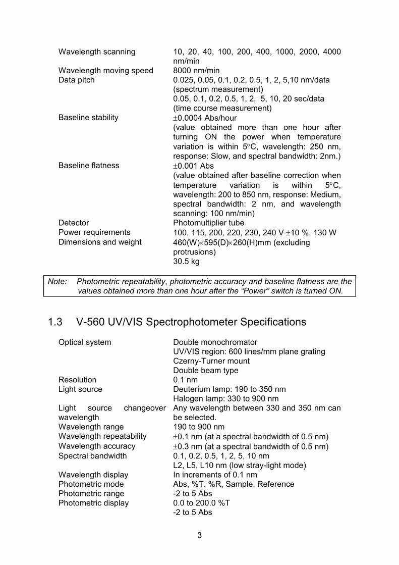
1.3 V-560 UV/VIS Spectrophotometer Specifications
Optical system Double monochromator UV/VIS region: 600 lines/mm plane grating Czerny-Turner mount Double beam type
Resolution 0.1 nm Light source Deuterium lamp: 190 to 350 nm
Halogen lamp: 330 to 900 nm Light source changeover wavelength
Any wavelength between 330 and 350 nm can be selected.
Wavelength range 190 to 900 nm Wavelength repeatability ±0.1 nm (at a spectral bandwidth of 0.5 nm) Wavelength accuracy ±0.3 nm (at a spectral bandwidth of 0.5 nm) Spectral bandwidth 0.1, 0.2, 0.5, 1, 2, 5, 10 nm
L2, L5, L10 nm (low stray-light mode) Wavelength display In increments of 0.1 nm Photometric mode Abs, %T. %R, Sample, Reference Photometric range -2 to 5 Abs Photometric display 0.0 to 200.0 %T
-2 to 5 Abs

4
Four digits and (-) symbol Displays up to 000.0 %T and 0.000 Abs
Photometric repeatability ±0.001 Abs (0 to 0.5 Abs)
±0.002 Abs (0.5 to 1 Abs) Photometric accuracy ±0.002 Abs (0 to 0.5 Abs)
±0.004 Abs (0.5 to 1 Abs)
±0.3 %T Note: Tested with NIST SRM 930D
Response Quick, Fast, Medium, Slow Stray light 0.0003 % (220 nm: NaI 10g/L aqueous solution;
340 nm: NaNO2 50g/L aqueous solution) Wavelength scanning speed 10, 20, 40, 100, 200, 400, 1000, 2000, 4000
nm/min Wavelength moving speed 8000 nm/min Data pitch 0.025, 0.05, 0.1, 0.2, 0.5, 1, 2, 5,10 nm/data
(spectrum measurement) 0.05, 0.1, 0.2, 0.5, 1, 2, 5, 10, 20 sec/data (time course measurement)
Baseline stability ±0.0004 Abs/hour (value obtained more than one hour after turning ON the power when temperature
variation is within 5°C, wavelength: 250 nm, response: Slow, and spectral bandwidth: 2nm)
Baseline flatness ±0.001 Abs (value obtained after baseline correction when
temperature variation is within 5°C, wavelength: 200 to 850 nm, response: Medium, spectral bandwidth: 2 nm, and wavelength scanning speed: 100 nm/min)
Detector Photomultiplier tube Power requirements 100, 115, 200, 220, 230, 240 V ±10 %, 130 W Dimensions and weight 460(W)×595(D)×260(H)mm (excluding
protrusions) 32 kg
Note: Photometric repeatability, photometric accuracy and baseline flatness are the values obtained more than one hour after the “Power” switch is turned ON.
1.4 V-570 UV/VIS/NIR Spectrophotometer Specifications
Optical system Single monochromator UV/VIS region: 1200 lines/mm plane grating NIR region: 300 lines/mm plane grating Czerny-Turner mount Double beam type
Resolution 0.1 nm (UV/VIS region) 0.5 nm (NIR region)

5
Light source Deuterium lamp: 190 to 350 nm Halogen lamp: 330 to 2500 nm
Light source changeover wavelength
Any wavelength between 330 and 350 nm can be selected.
Detector changeover wavelength
Any wavelength between 750 and 900 nm can be selected.
Wavelength range 190 to 2500 nm Wavelength repeatability UV/VIS region: ±0.1 nm (at a spectral bandwidth of 0.5 nm) NIR region: ±0.4 nm (at a spectral bandwidth of 2.0 nm) Wavelength accuracy UV/VIS region: ±0.3 nm (at a spectral bandwidth of 0.5 nm) NIR region: ±1.5 nm (at a spectral bandwidth of 2.0 nm) Spectral bandwidth 0.1, 0.2, 0.5, 1, 2, 5, 10 nm (UV/VIS region)
L2, L5, L10 nm (low stray-light mode) 0.4, 0.8, 1, 2, 4, 8, 20, 40 nm (NIR region)
Wavelength display In increments of 0.1 nm Photometric mode Abs, %T. %R, Sample, Reference Photometric range -2 to 3 Abs (UV/VIS region)
-0.3 to 3 Abs (NIR region) Photometric display 0.0 to 200.0 %T
-2 to 5 Abs Four digits and (-) symbol Displays up to 000.0 %T and 0.000 Abs
Photometric repeatability ±0.001 Abs (0 to 0.5 Abs)
±0.002 Abs (0.5 to 1 Abs) Photometric accuracy ±0.002 Abs (0 to 0.5 Abs)
±0.004 Abs (0.5 to 1 Abs)
±0.3 %T Note: Tested with NIST SRM 930D
Response Quick, Fast, Medium, Slow Stray light UV/VIS region: 0.015% (220 nm: NaI 10g/L aqueous solution;
340 nm: NaNO2 50g/L aqueous solution) NIR region: 0.1% (1690 nm: CH2Br2 10 mm cell used) Wavelength scanning speed 10, 20, 40, 100, 200, 400, 1000, 2000, 4000
nm/min Wavelength moving speed 8000 nm/min(UV/VIS region)
32000 nm/min(NIR region) Data pitch 0.025, 0.05, 0.1, 0.2, 0.5, 1, 2, 5, 10 nm/data
(UV/VIR spectrum measurement) 0.1, 0.2, 0.5, 1, 2 , 5, 10 nm/data (NIR spectrum measurement) 0.05, 0.1, 0.2, 0.5, 1, 2, 5, 10, 20 sec /data (time course measurement)
Baseline stability ±0.0004 Abs/hour (value obtained more than one hour after turning ON the power when temperature
variation is within 5°C, wavelength: 250 nm,

6
response: Slow, and spectral bandwidth: 2nm) Baseline flatness ±0.001 Abs
(value obtained after baseline correction when
temperature variation is within 5°C, wavelength: 250 to 850 nm, response: Medium, spectral bandwidth: 2 nm, and wavelength scanning speed: 400 nm/min, wavelength: 850 to 2500 nm, spectral bandwidth: 8 nm,)
Detector Photomultiplier tube Pbs photoconductive cell
Power requirements 100, 115, 200, 220, 230, 240 V ±10 %, 180 W Dimensions and weight Main unit 460(W)×595(D)×260(H) mm (excluding
protrusions) 33 kg
Pbs power supply unit 100(W)×170(D)×125(H) mm (excluding protrusions) 1.9 kg
Note: Photometric repeatability, photometric accuracy and baseline flatness are the values obtained more than one hour after the “Power” switch is turned ON.

7
2 General Description of Instrument 2.1 V-530 Spectrophotometer Optical System 2.1.1 Optical System The V-530 is designed to measure the absorption spectrum of a sample at wavelengths in the range 190 to 1100 nm. The light sources used in the V-530 are a deuterium(D2) lamp (190 to 350 nm) for the UV region and a halogen (WI) lamp (340 to 1100 nm) for the VIS/NIR region. The light from the light source is converged and enters the monochromator. The light is dispersed by the grating in the monochromator and converges onto the exit slit. The light that has passed through the exit slit is monochromated. This light is split into two beams, one going to the sample to be measured and the other to the reference sample such as a solvent. The light that has passed through the sample and the reference sample is alternately incident upon the silicon photodiode.
D
D
Ref
Sam
F
G
WI
M5 M2
M(BS)
3
S2
S1
D2
M1
M4
WI
D2
S
F
G
BS
D
Sam
Ref
Deuterium lamp
halogen lamp
Slit
Filter
Grating
Bean splitter
Detector
Sample beam
Reference beam
Figure 2.1 V-530 Optical system
2.1.2 Electrical System The configuration of the electrical system used in the V-530 is shown in Fig 2.2. The light incident upon the silicon photodiode is converted into an electrical signal and, after being subjected to synchronous rectification, is converted into a digital signal and enters the microcomputer. The signal processed by the microcomputer is displayed on the display unit as digital data or a spectrum. Actions such as light source changeover, wavelength drive, filter drive, etc. are controlled by the microcomputer.

8
D2 lamp
CPU, ROM, RAM, I/O
D/A
A/DMirror
Filter
Monochromator
Limiter
WI lamp
Serial 1
Serial 2
Accessory input Sccessory output
CoarseAdj.
FineAdj.
Detector Amp.
Battery
Main unit
320×240
10×6 キー
CPUROM, RAMI/O
I/O
LCDROM Card
RAM Card
Autozero Goto WL File
Start Stop Print
iRM
Touch key
LCDCintroller
Battery
Centronics
Serial 1
Power supply
Figure 2.2 V-530 Electrical system

9
2.2 V-550/560/570 Spectrophotometers Optical System 2.2.1 Optical System Figures 2.3 through 2.5 show the optical systems of the V-550, V-560 and V–570 spectrophotometers, respectively. The V-550 and V-560 measure the absorption spectrum of a sample at wavelengths in the range 190 to 900 nm and the V-570 measures the absorption spectrum of a sample at wavelengths in the range 190 to 2500 nm. In each model, the light sources used are a deuterium (D2) lamp (190 to 350 nm) for use in the ultraviolet region and Halogen (WI) lamp (340 to 2500 nm) for use in the VIS/NIR region. The light from the light source is converged and enters the monochromator. It is dispersed by the grating in the monochromator and the light passing through the exit slit is monochromated. This light is split into two light paths by a sector mirror, one incident on the sample to be measured and the other on the reference sample such as a solvent. The light that has passed through the sample and reference sample is incident on the photomultiplier tube or Pbs photoconductive cell.
Figure 2.3 V-550 Optical system
WI, D2 : Light source M : Mirror S : Slit F : Filter G : Grating M8 : beam splitter PM : Detector Sam : Sample beam Ref : Reference beam W : window

10
Figure 2.4 V-560 Optical system
Figure 2.5 V-570 Optical system
WI, D2 : Light source M : Mirror S : Slit F : Filter G : Grating M8 : beam splitter PM : Detector Sam : Sample beam Ref : Reference beam W : window
WI, D2 : Light source M : Mirror S : Slit F : Filter G : Grating M8 : beam splitter PM : UV/VIS Detector Pbs : NIR detector Sam : Sample beam Ref : Reference beam W : window
11
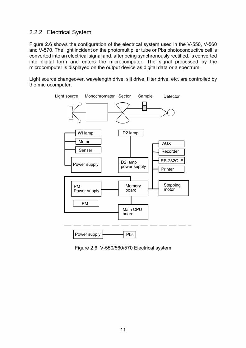
2.2.2 Electrical System Figure 2.6 shows the configuration of the electrical system used in the V-550, V-560 and V-570. The light incident on the photomultiplier tube or Pbs photoconductive cell is converted into an electrical signal and, after being synchronously rectified, is converted into digital form and enters the microcomputer. The signal processed by the microcomputer is displayed on the output device as digital data or a spectrum. Light source changeover, wavelength drive, slit drive, filter drive, etc. are controlled by the microcomputer.
WI lamp
Motor
Senser
D2 lamp
Power supplyD2 lamppower supply
AUX
Recorder
RS-232C IF
Printer
PM Power supply
Memoryboard
PM
Main CPU board
Steppingmotor
Power supply Pbs
Light source Monochromater Sector Sample Detector
Figure 2.6 V-550/560/570 Electrical system

12
3 Nomenclature and Functions of Components 3.1 V-530 Spectrophotometer: Overview 3.1.1 Overview
"Power" switch
Sample chamber
Fixing screwIndicator lamp
Light source lid
Figure 3.1 Overview
Component Function Sample chamber Slide the lid to open and gain access to the reference and
sample cell holders. The cell holder closest to the front of the instrument is the sample cell holder.
Fixing screws Fixes the sample chamber in position. To mount the optional sample chamber, loosen these screws and remove the standard sample chamber.
“Power” switch Indicator lamp
The indicator lamp is lit when power is on.
Light source lid Lift to open and gain access to the light source.

13
3.1.2 Rear Panel
"AC Inlet" "Fuse" "GND"
"iRM PS"
"Serial A"
"Serial B"
"Recorder"
"AUX"
Warning label
Figure 3.2 V-530 rear panel
Component Function
AC Inlet Accepts the power cable. GND Grounding terminal Fuse Fuses for the main unit (two time-lag fuses) iRM PS Accepts the remote module power cable. Printer Connector for connecting the printer/plotter cable Serial A Connector for connecting the communication cable to DS or iRM Serial B Connector for connecting theRS-232C cable Recorder Terminal for analog output.
The value specified by setting the ordinate is recorded in the range 0 to 1 V.
AUX Auxiliary connector for connecting an accessory, such as a quick flow sampler.
Warning label Warning labels for fuse and ground (see page ii)

14
3.2 V-550/560/570 Spectrophotometers: Overview 3.2.1 Overview
"Power" switch
Sample chamber
Fixing screw
Indicotor lamp
Light source lid
Pbs power supply unit Figure 3.3 V-550/560/570 overview
Component Function
Sample chamber Slide the lid to open and gain access to the reference and sample cell holders. The cell holder closest to the front of the instrument is the sample cell holder.
Fixing screws
Fix the sample chamber in position. To mount the optional sample chamber, loosen these screws and remove the standard sample chamber.
“Power” switch Indicator lamp
The indicator lamp is lit when power is on.
Light source lid Lift to open and gain access to the light source. Pbs power supply unit
<V-570 only> Power supply unit for the V-570 detector.

15
3.2.2 Rear Panel
"AC Inlet"
"iRM PS""Recorder"
"Serial A"
"Serial B"
"Aux"
"GND" "Fuse"
Warning label
Figure 3.4 V-550/560/570 Rear panel
Component Function
AC Inlet Accepts the power input cable. GND Ground terminal Fuse Fuses for the main unit (two time-lag fuses) iRM PS Accepts the remote module power cable. Serial A Connector for connecting the communication cable to DS or
iRM Serial B Connector for connecting the RS-232C cable. Recorder Terminal for analog output.
The value specified by setting the ordinate is recorded in the range 0 to 1 V.
AUX Auxiliary connector for connecting an accessory, such as a quick flow sampler.
Warning label Warning labels for fuse and ground (see page ii).
16
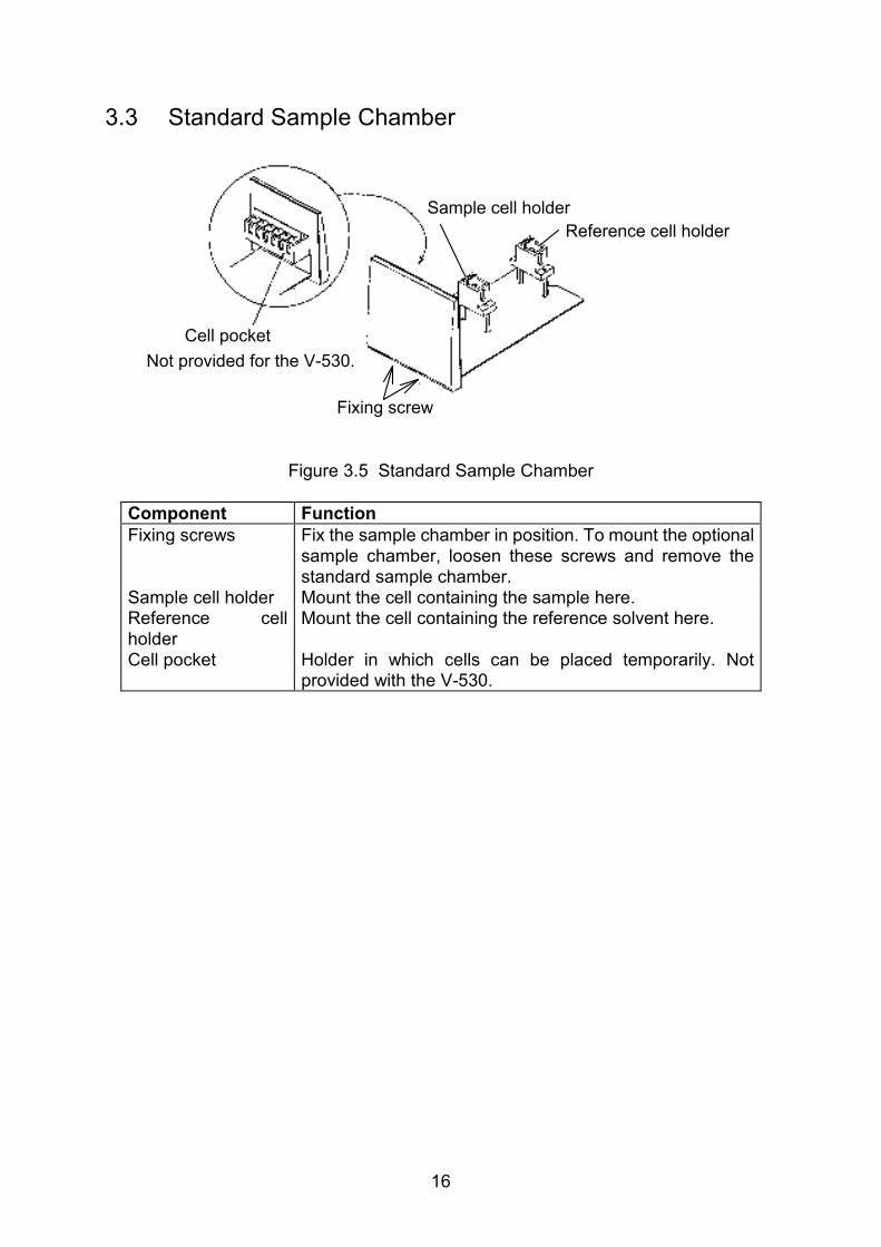
3.3 Standard Sample Chamber
Sample cell holder
Reference cell holder
Fixing screw
Cell pocket
Not provided for the V-530.
Figure 3.5 Standard Sample Chamber
Component Function
Fixing screws Fix the sample chamber in position. To mount the optional sample chamber, loosen these screws and remove the standard sample chamber.
Sample cell holder Mount the cell containing the sample here. Reference cell holder
Mount the cell containing the reference solvent here.
Cell pocket Holder in which cells can be placed temporarily. Not provided with the V-530.

17
3.4 Intelligent Remote Module
Display panel
Operation panelCard slot
Overview
"Serial A""Printer""Contrast"
Power cable Rear panel
Figure 3.6 Intelligent remote module
Component Function
Display panel 320x240 pixel LCD. Displays wavelength, absorbance, measurement parameters, etc. Also used for selecting menus, and editing measurement parameters via the touch key pad.
Operation panel Contains keys for operating the monochromator, printer, etc.
[Stop] Press to stop measurement. [Print] Press to print out data, measurement parameters, etc. [File] Press to save/load parameters and data. [GotoWL] Press to move to a different wavelength. [Autozero] Press to “zero” absorbance (or 100%T). [Start] Press to start measurement. Card slot Accepts a memory card. Rear panel Contrast Turn to adjust the contrast of the display panel. Power cable Connects to the “iRM PS” connector on the rear of the main
unit. Printer Connector for connecting a printer cable Serial A Connector for connecting Serial A on the rear of the main
unit
18
4 Maintenance This section contains instructions on how to clean the sample chamber when a sample is spilt, how to run the performance check to see if the instrument is operating normally, and on replacing consumables. Give consideration to the environment in which the instrument is to be operated. Keep the instrument and surrounding area clean so that the spectrophotometer may be used in a stabilized condition over a long period.
Note1: The operating procedure varies with the type of instrument. Operation is
described by instrument type. Read the portion relevant to your instrument.
Note2: It is recommended that the validation program (optional) is used for the performance check.
4.1 Cautions for Routine Operation (1) Before operating the instrument, allow the instrument to warm-up for at least 15
minutes after turning the power on. (2) Do not place anything on the instrument. (3) When measurement is complete, remove the sample from the sample chamber.
4.2 Cleaning the Sample Chamber If a sample is spilt in the sample chamber, quickly wipe up the spillage with gauze or similar material, remove the sample chamber, and clean it using the following procedure.
CAUTION: Use ethanol to clean the sample chamber. Do not use other types of
organic solvent as this may remove the instrument paint.
(1) Removing the sample chamber
a) Open the sample chamber lid and loosen the two fixing screws on the front underside of the sample chamber by hand (see Fig. 3.1 or Fig. 3.3).
b) Pull the sample chamber toward you a little and lift to remove the sample chamber holder along with the cell holders.
(2) Cleaning the sample chamber
<<When the sample is soluble in water>> Wipe up the spilt sample with gauze or similar material. Remove any trace of the spillage with gauze soaked in water. Finally, remove moisture content with gauze soaked in ethanol and allow to dry. <<When the sample is insoluble in water>> Wipe up the spilt sample with gauze or similar material. Remove any trace of the spillage with gauze soaked in ethanol and allow to dry.

19
(3) Remounting the sample chamber a) Locate the sample chamber over the two positioning pins on the main unit and move it all the way to the back. b) Ensure that light is incident upon the center of the cell holder. To check it visually, set the wavelength to 500 nm and place a piece of white paper in front of the cell holder. c) Firmly tighten the two fixing screws and close the lid.
4.3 Performance Check: Data Station Type A performance check should be run approx. once a month to ensure the normal instrument performance. If the instrument is not operating properly, conduct checks and take corrective action after referring to the troubleshooting chart in Section 5. After taking corrective action, run the performance check again to verify that the instrument has been restored to normal.
Note: This section provides a simple description of operating procedures. For
details, refer to the Operations manual.
Baseline flatness Refer to Section 4.3.1 Wavelength repeatability Refer to Section 4.3.2 Wavelength accuracy Refer to Section 4.3.3
4.3.1 Baseline (Abs 0 line) Flatness This check should be performed more than one hour after turning the instrument on. (1) Start the [Spectrum Measurement] program from the [Spectra Manager] window. (2) Click [Measurement]-[Spectrum Parameters...] and set parameters as follows:
V-530 measurement parameters V-550/560/570 measurement parameters
Photometric Mode Abs Photometric Mode Abs Response Medium Response Medium Scanning Speed 200 nm/min Band Width 2.0 nm Start 1000 nm Scanning Speed 200 nm/min End 200 nm Start 850 nm Data Pitch 1.0 nm End 200 nm Display -0.005~+0.005 Data Pitch 1.0 nm No of Cycles 1 Display -0.005~+0.005 No of Cycles 1
(3) Measure the baseline as follows.
a) Click [Measurement]-[Baseline...]. The [Baseline Correction] dialog box appears.
b) Click the <Measure...> button to display the [Baseline Measurement] dialog box.
c) Make sure that the sample chamber is empty and then click the <Start> button. The baseline is measured and stored in the memory of the spectrophotometer.
20
Note: This data is used for correcting the baseline spectrum (0 Abs line) to be measured in (4) below.
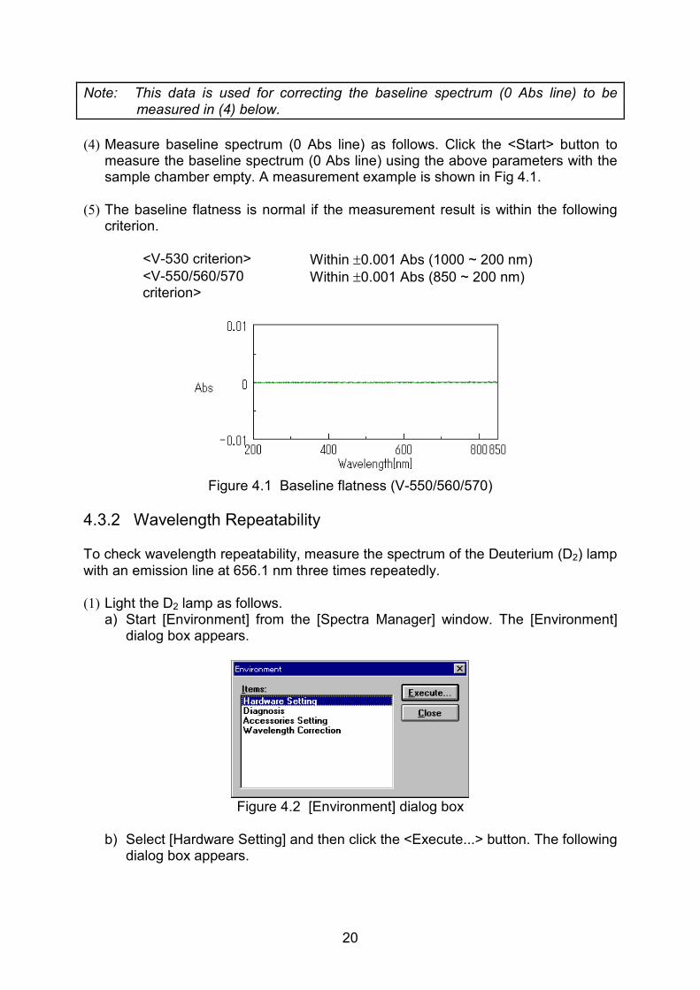
(4) Measure baseline spectrum (0 Abs line) as follows. Click the <Start> button to
measure the baseline spectrum (0 Abs line) using the above parameters with the sample chamber empty. A measurement example is shown in Fig 4.1.
(5) The baseline flatness is normal if the measurement result is within the following
criterion.
<V-530 criterion> Within ±0.001 Abs (1000 ~ 200 nm) <V-550/560/570 criterion>
Within ±0.001 Abs (850 ~ 200 nm)
Figure 4.1 Baseline flatness (V-550/560/570)
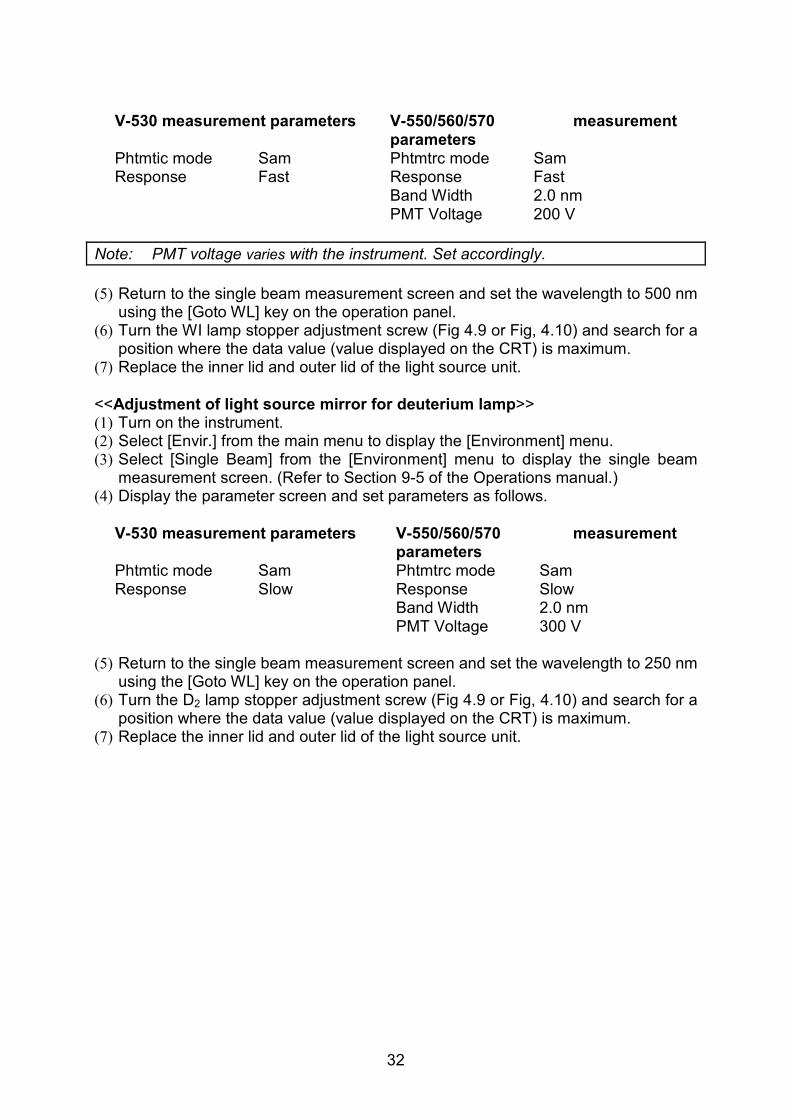
4.3.2 Wavelength Repeatability To check wavelength repeatability, measure the spectrum of the Deuterium (D2) lamp with an emission line at 656.1 nm three times repeatedly. (1) Light the D2 lamp as follows.
a) Start [Environment] from the [Spectra Manager] window. The [Environment] dialog box appears.
Figure 4.2 [Environment] dialog box
b) Select [Hardware Setting] and then click the <Execute...> button. The following
dialog box appears.

21
Figure 4.3 [Hardware Setting] dialog box
c) Check the [Deuterium] box and uncheck the [Halogen] box. d) Click <OK> to close the dialog box. Only the D2 lamp is lit.
(2) Start [Spectrum Measurement] from the [Spectra Manager] window and set the
following parameters.
V-530 Measurement parameters V-550/560/570 measurement parameters
Photometric Mode Sample Photometric Mode Sample Response Fast Response Fast Scanning Speed 40 nm/min Band Width 0.5 nm Start 658 nm Scanning Speed 10 nm/min End 654 nm Start 658 nm Data Pitch 0.1 nm End 654 nm Display 0~100 Data Pitch 0.025 nm No of Cycles 3 Display 0~100 Cycle Time 1 sec PMT Voltage 300 V No of Cycles 3 Cycle Time 1 sec
Note: PMT voltage varies with the instrument. Set properly.
<Automatic spectrum save parameters> [Auto Save] Select (Check) [File name] Enter a filename (up to 5 characters) (3) With the sample chamber empty, measure the spectrum of the D2 lamp with an
emission line at 656.1 nm three times. (4) Start [Spectra Analysis] from the [Spectra Manager] window and overlay the three
spectra in a View (refer to the “Spectra Analysis Operation Manual”). An example is shown in Fig 4.4.

22
Figure 4.4 D2 lamp spectra with an emission line at 656.1 nm
(5) The wavelength repeatability is normal if it is within the following criterion.
Criterion: Within ±0.1 nm of the average value of the peaks of the spectrum with an emission line at 656.1 nm
(6) Display the [Environment] menu again and return to the original settings (i.e. check
the [Deuterium] and [Halogen] boxes).
4.3.3 Wavelength Accuracy To check wavelength accuracy, measure the spectra of the D2 lamp with an emission line at 656.1 nm and 486.0 nm. (1) Light only the Deuterium lamp (see item (1) in Section 4.3.2). (2) Start [Spectrum Measurement] from the [Spectra Manager] window and set the
following parameters.
<<Parameters for spectrum with an emission line at 656.1 nm>> V-530 measurement parameters V-550/560/570 measurement
parameters Photometric Mode Sample Photometric Mode Sample Response Fast Response Fast Scanning Speed 40 nm/min Band Width 0.5 nm Start 658 nm Scanning Speed 10 nm/min End 654 nm Start 658 nm Data Pitch 0.1 nm End 654 nm Display 0~100 Data Pitch 0.025 nm No. of Cycles 1 Display 0~100 PMT Voltage 300 V No. of Cycles 1
Note: PMT voltage varies with the instrument. Set properly.
<<Parameters for spectrum with an emission line 486.0 nm>>
Start 488 nm End 484 nm All other parameter settings are the same parameters as shown above.

23
(3) Measure the spectrum of the D2 lamp with an emission line at 656.1 nm and at 486.0 nm with the sample chamber empty. Measurement examples are shown in Fig. 4.5 and Fig. 4.6.
Figure 4.5 D2 lamp spectrum with emission line at 656.1 nm
Figure 4.6 D2 lamp spectrum with emission line at 486.0 nm
(4) Wavelength accuracy is normal if the measurement result in within the following
criteria.
<V-530 criteria> Within 656.1 ± 0.5 nm
Within 486.0 ± 0.5 nm
<V-550/560/570 criteria> Within 656.1 ± 0.3 nm
Within 486.0 ± 0.3 nm (5) Display the [Environment] menu again and return to the original settings (i.e. check
the [Deuterium] and [Halogen] boxes).

24
4.4 Performance Check: Intelligent Remote Module Type A performance check should be run approx. once a month to ensure the normal instrument performance. If the instrument is not operating properly, conduct checks and take corrective action after referring to the troubleshooting chart in Section 5. After taking corrective action, run the performance check again to verify that the instrument has been restored to normal.
Note: This section provides a simple description of operating procedures. For details, refer to the Operations manual.
Baseline flatness Refer to Section 4.4.1 Wavelength repeatability Refer to Section 4.4.2 Wavelength accuracy Refer to Section 4.4.3
4.4.1 Baseline (Abs 0 line) Flatness
This check should be performed more than one hour after turning the instrument on.
(1) Select [Spectrum] from the main menu and measure the baseline of the entire region after setting the following parameters. (Refer to Section 5-4 of the Operations manual.)
Response Medium Scanning speed 100 nm/min This data is stored in the baseline memory.
Note: This data is used for correcting the baseline spectrum (0 Abs line) to be measured in (2) below.
(2) Set the following parameter and measure the baseline spectrum (0 Abs line) with
the sample chamber empty. (Refer to Section 5-3 of the Operations manual.) A measurement example is shown in Fig 4.1.
V-530 measurement parameters V-550/560/570 measurement parameters
Phtmtrc mode Abs Phtmtrc mode Abs Response Medium Response Medium Start WL 1000 nm Band width 10 nm End WL 200 nm Start WL 850 nm Data interval 1.0 nm End WL 200 nm Scan. speed 200 nm/min Data interval 1.0 nm No. of Cycles 1 Scan. speed 200 nm/min Lower scale -0.005 or more No. of Cycles1 Upper scale +0.005 Abs Lower scale -0.005 or more Upper scale +0.005 Abs

25
(3) The baseline flatness is normal if the measurement result is within the following criterion.
<V-530 criterion> Within ±0.001 Abs (1000 200 nm)
<V-550/560/570 criterion> Within ±0.001 Abs (850 200 nm)
4.4.2 Wavelength Repeatability Measure the spectrum of the deuterium(D2) lamp with an emission line at 656.1 nm three times repeatedly to check its repeatability. (1) Select [Envir] from the main menu to display the [Environment] menu. (2) From the [Environment] menu, select [Other] to display the [Other] screen. (3) Set the light source to [D2] (to light only the Deuterium lamp). (Refer to Section 9-7
of the Operations manual.) (4) Select [Single Beam] from the [Environment] menu to display the [Single Beam]
screen. (5) Display the [Parameter] screen and set the following parameters.
V-530 measurement parameters V-550/560/570 measurement parameters
Phtmtrc mode Sam Phtmtrc mode Sam Response Fast Response Fast Start WL 658 nm Band width 0.5 nm End WL 654 nm Start WL 658 nm Data interval 0.1 nm End WL 654 nm Scan. speed 40 nm/min Data interval 0.025 nm No. of Cycles 3 Scan. speed 10 nm/min Lower scale 0 No. of Cycles 3 Upper scale 100 Lower scale 0 Upper scale 100 HT Voltage 300 V
Note: PMT voltage varies with instrument. Set accordingly.
(6) Measure the single beam spectrum with the sample chamber empty three times to obtain three D2 lamp spectra with an emission line at 656.1 nm. A measurement example is shown in Fig 4.4.
(7) The wavelength repeatability is normal if it is within the following criterion.
Criterion: Within ±0.1 nm of the average value of the peak of the emission line spectrum at 656.1 nm
(8) Display the [Others] screen again and return to the original settings (WI and D2).

26
4.4.3 Wavelength Accuracy Measure the spectra of the D2 lamp with emission lines at 656.1 nm and at 486.0 nm and read the peak wavelength. (1) Light only the Deuterium lamp by following items (1) to (3) in Section 4.4.2. (2) Select [Single Beam] from the [Environment] menu to display the [Single Beam]
screen. (Refer to Section 9-5 of the Operations manual.) (3) Display the [Parameter] screen and set the following parameters.
<<Parameters for spectrum with an emission line 656.1 nm>> V-530 measurement parameters V-550/560/570 measurement
parameters Phtmtrc mode Sam Phtmtrc mode Sam Response Fast Response Fast Start WL 658 nm Band width 0.5 nm End WL 654 nm Start WL 658 nm Data interval 0.1 nm End WL 654 nm Scan. speed 40 nm/min Data interval 0.025 nm No. of Cycles 1 Scan. speed 10 nm/min Lower scale 0 No. of Cycles 1 Upper scale 100 Lower scale 0 Upper scale 100 HT Voltage 300 V
Note: PMT voltage varies with the instrument. Set accordingly.
<<Parameters for spectrum with an emission line 486.0 nm>> Start WL 488 nm End WL 484 nm All other parameter settings are the same as shown above. (4) Measure the single beam spectrum with the sample chamber empty to obtain the
emission line spectra of the D2 lamp. Measurement examples are shown in Fig 4.5 and Fig. 4.6.
(5) Wavelength accuracy is normal if the measurement results are within the following criteria.
<V-530 criteria> Within 656.1 0.5 nm Within 486.0 0.5 nm <V-550/560/570 criteria> Within 656.1 0.3 nm Within 486.0 0.3 nm (6) Display the [Others] screen again and return to the original settings (WI & D2).

27
4.5 Replacement of Consumables 4.5.1 Replacement of Fuse The instruments covered in this manual use 2A time-lag type fuses when using a 100 V voltage supply and 1A time-lag type fuses when using a 200 V voltage supply. 100 V to 120 V: 2A time-lag type fuse 200 V to 240 V: 1A time-lag type fuse
WARNING: Only use fuses of the rated capacity to prevent injury to personnel and instrument overheating.
WARNING: Always turn Off the “Power” switch and unplug the AC power cable from
the outlet before replacing a fuse.
Use the following procedure when replacing a fuse. (1) Turn off the power and unplug the AC power cable from the outlet. (2) Insert a flat-headed screwdriver into the fuse holder at the rear of instrument (Fig.
4.7). Push and turn about 90° counterclockwise to remove the fuse holder and fuse.
(3) Remove the old fuse and insert a new fuse into the holder. Replace the fuse holder,
and push and turn the holder 90° clockwise to lock. (4) Plug the power cable into the electrical outlet and turn on the power to operate the
unit. If the fuse blows again soon after replacement, contact your local JASCO distributor.
Fuse
Figure 4.7 V-550/560/570 rear panel

28
4.5.2 Lamp Replacement and Adjusting the Light Source Mirror The lifetime of both the Deuterium(D2) lamp and the Halogen (WI) lamp is approx. 1000 hours. After prolonged use, luminous energy decrease in turn causing the level of noise in the measured data to increase.
4.5.2.1 Lamp Replacement
WARNINGS: (1) The lamp is hot when lit. Therefore, before replacing the lamp, switch
off the light source and wait for at least 10 minutes. (2) Before attempting to replace the lamp, turn off the power and remove
the power cable from the outlet.
CAUTIONS: (1) Loosen only the screws required for lamp replacement. (2) When handling the lamp, ware clean, cloth gloves. Never handle the
lamp with bare hands. (3) Never touch the mirror or any other optical elements by hand. (4) If the lamp surface is contaminated, clean it with gauze soaked in
ethanol and wipe it with dry clean gauze.
<<Replacement of Halogen(WI) lamp>> (1) Slide the outer lid of the light source unit to remove it and then remove the inner lid
(Fig 4.8). (2) Pull out the Halogen lamp from the socket (Fig. 4.9 or Fig. 4.10). (3) Insert a new Halogen lamp into the socket. (4) For the DS type, adjust the light source mirror as described in Section 4.5.2.2.
For the iRM type, adjust the light source mirror as described in Section 4.5.2.3.
Figure 4.8 Removal of light source lid (V-550/560/570)

29
D2WI
D2
WI
lamp stopperadjustment screw
lamp
lamp stopperadjustment screw
lamp
Figure 4.9 Light source unit (V-530)
D2 WI
D2 lamp stopperadjustment screw
lamp
WI lamp stopperadjustment screw
lamp
Figure 4.10 Light source unit (V-550/560/570) <<Replacement of Deuterium lamp>> (1) Slide the outer lid of the light source unit to remove it and then remove the inner lid
(Fig 4.8). (2) Pull out the Deuterium lamp from the socket (Fig. 4.9 or Fig. 4.10). (3) Insert a new deuterium lamp into the socket. (4) For the DS type, adjust the light source mirror as described in Section 4.5.2.2.
With the iRM type, adjust the light source mirror as described in Section 4.5.2.3.

30
4.5.2.2 Adjustment of DS type light source mirror When the light source is replaced, if the beam from the lamp is not incident upon the entrance slit, troubles will arise, such as lack of luminous energy, bend of the baseline, and deviation of the measurement value. Whenever the lamp is replaced, be sure to adjust the light source mirror.
WARNINGS: (1) The lamp is hot when lit. Do not touch with bare hands. (2) Wear glasses (ordinary glasses or sunglasses) during adjustment to
protect your eyes from ultraviolet rays. (3) Do not touch the wiring either with your hand or with a screwdriver.
Contact with the wiring may cause electric shock.
CAUTION: Loosen only the screws required for adjustment.
<<Adjustment of light source mirror for Halogen lamp>> (1) Turn on the instrument. (2) Start [Time Course Measurement] from the [Spectra Manager] window and set the
following parameters. V-530 measurement parameters V-550/560/570 measurement
parameters Photometric mode Sample Photometric mode Sample Response Fast Response Fast Wavelength 500 nm Band Width 2.0 nm Start Time 0 sec Wavelength 500 nm End Time 60 sec Start Time 0 sec Data Pitch 5.00 sec End Time 60 sec Data Pitch 5.00 sec PMT Voltage 200 V
Note: PMT voltage differs with instrument. Set accordingly.
CAUTION: Do not loosen screws other than the adjustment screw for the stopper.
(3) Turn the WI lamp stopper adjustment screw (Fig 4.9 or Fig, 4.10) and search for a
position where the data value (value displayed on the CRT) is maximum. (4) Replace the inner lid and outer lid of the light source unit. <<Adjustment of light source mirror for Deuterium lamp>> (1) Turn on the instrument. (2) Start [Time Course Measurement] from the [Spectra Manager] window and set the
following parameters.

31
V-530 measurement parameters V-550/560/570 measurement parameters
Photometric mode Sample Photometric mode Sample Response Slow Response Slow Wavelength 250 nm Band Width 2.0 nm Start Time 0 sec Wavelength 250 nm End Time 60 sec Start Time 0 sec Data Pitch 5.00 sec End Time 60 sec Data Pitch 5.00 sec
PMT Voltage 300 V
Note: PMT voltage varies with the instrument. Set accordingly.
CAUTION: Do not loosen screws other than the adjustment screw for the stopper.
(3) Turn the D2 lamp stopper adjustment screw (Fig 4.9 or Fig, 4.10) and search for a
position where the data value (value displayed on the CRT) is maximum. (4) Replace the inner lid and outer lid of the light source unit.
4.5.2.3 Adjustment of iRM type light source mirror When the light source is replaced, if the beam from the lamp is not correctly incident upon the entrance slit, troubles will arise, such as lack of luminous energy, bend of the baseline, and deviation of the measurement value. Whenever the lamp is replaced, be sure to adjust the light source mirror.
WARNINGS: (1) The lamp is hot when lit. Do not touch with bare hands. (2) Wear glasses (ordinary glasses or sunglasses) during adjustment to
protect your eyes from ultraviolet rays. (3) Do not touch the wiring either with your hand or with a screwdriver.
Contact with the wiring may cause electric shock.
CAUTION: Loosen only the screws required for adjustment.
<<Adjustment of light source mirror for halogen lamp>> (1) Turn on the instrument. (2) Select [Envir.] from the main menu to display the [Environment] menu. (3) Select [Single Beam] from the [Environment] menu to display the single beam
measurement screen. (Refer to Section 9-5 of the Operations manual.) (4) Display the parameter screen and set parameters as shown below.
32
V-530 measurement parameters V-550/560/570 measurement parameters
Phtmtic mode Sam Phtmtrc mode Sam Response Fast Response Fast Band Width 2.0 nm PMT Voltage 200 V
Note: PMT voltage varies with the instrument. Set accordingly.
(5) Return to the single beam measurement screen and set the wavelength to 500 nm
using the [Goto WL] key on the operation panel. (6) Turn the WI lamp stopper adjustment screw (Fig 4.9 or Fig, 4.10) and search for a
position where the data value (value displayed on the CRT) is maximum. (7) Replace the inner lid and outer lid of the light source unit. <<Adjustment of light source mirror for deuterium lamp>> (1) Turn on the instrument. (2) Select [Envir.] from the main menu to display the [Environment] menu. (3) Select [Single Beam] from the [Environment] menu to display the single beam
measurement screen. (Refer to Section 9-5 of the Operations manual.) (4) Display the parameter screen and set parameters as follows.
V-530 measurement parameters V-550/560/570 measurement parameters
Phtmtic mode Sam Phtmtrc mode Sam Response Slow Response Slow Band Width 2.0 nm PMT Voltage 300 V
(5) Return to the single beam measurement screen and set the wavelength to 250 nm
using the [Goto WL] key on the operation panel. (6) Turn the D2 lamp stopper adjustment screw (Fig 4.9 or Fig, 4.10) and search for a
position where the data value (value displayed on the CRT) is maximum. (7) Replace the inner lid and outer lid of the light source unit.

33
5 Troubleshooting If the spectrophotometer does not operate normally, the following causes are suspected:
• Erroneous operation
• Deterioration of consumable part or parts
• Instrument trouble Possible causes and corrective actions against troubles are given below in the troubleshooting chart. In the event that the trouble cannot be corrected after following the actions given in the troubleshooting chart, contact your local JASCO distributor and provide the model name and serial number of your instrument together with a complete description of the problem. When checking the instrument, observe the following warnings and cautions.
WARNINGS: (1) Do not directly look at the light (ultraviolet light) emitted from the
Deuterium lamp as this may injure your eye. Wear glasses (ordinary glasses or sunglasses) during adjustment.
(2) The lamp is very hot when lit. When the lamp is lit do not touch with bare hands. Before replacing the lamp, wait for at least 15 minutes after turning off the lamp until the lamp cools down.
(3) Before checking the electrical system, be sure to turn off the power switch.
CAUTIONS: (1) Before plugging in the AC power cable, ensure that the power switch is
in the Off position.
(2) Never touch the mirror or other optical elements with bare hands.
34
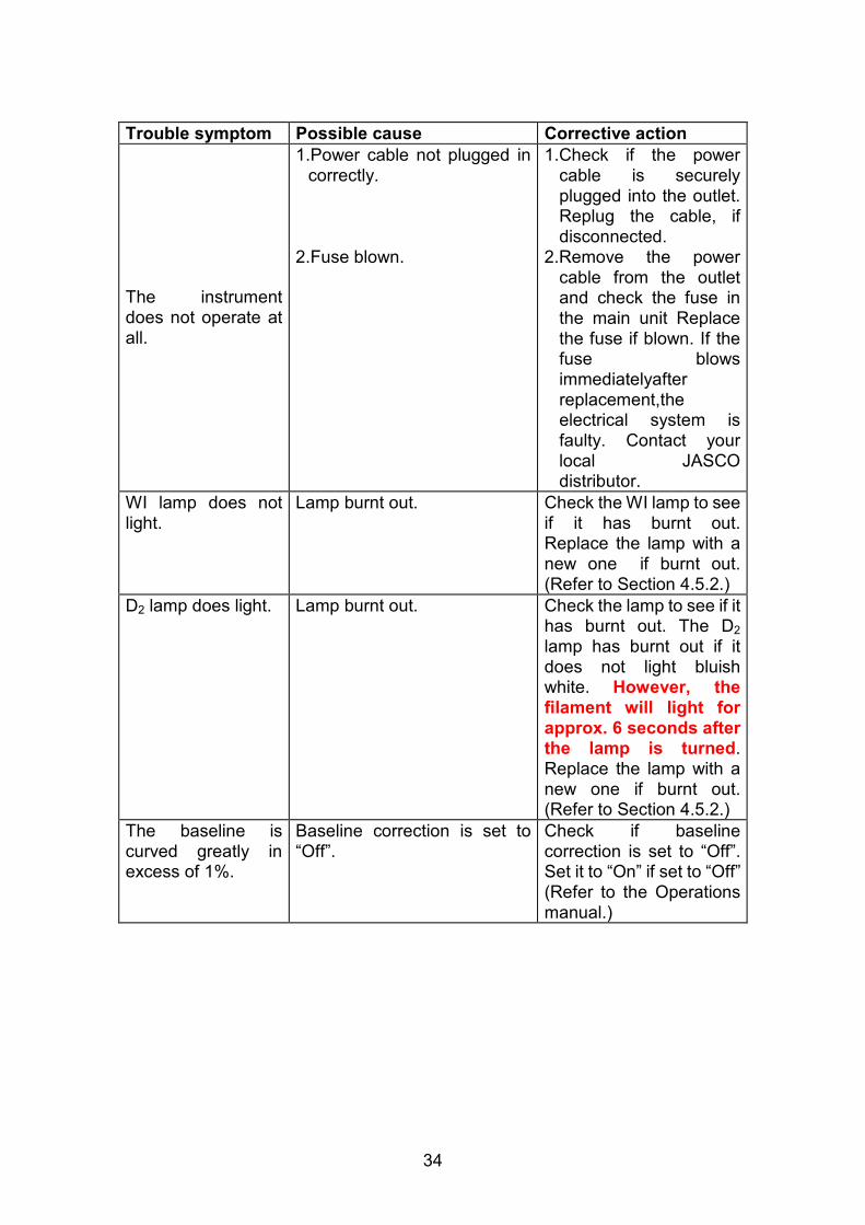
Trouble symptom Possible cause Corrective action
1.Power cable not plugged in correctly.
1.Check if the power cable is securely plugged into the outlet. Replug the cable, if disconnected.
The instrument does not operate at all.
2.Fuse blown. 2.Remove the power cable from the outlet and check the fuse in the main unit Replace the fuse if blown. If the fuse blows immediatelyafter replacement,the electrical system is faulty. Contact your local JASCO distributor.
WI lamp does not light.
Lamp burnt out. Check the WI lamp to see if it has burnt out. Replace the lamp with a new one if burnt out. (Refer to Section 4.5.2.)
D2 lamp does light. Lamp burnt out. Check the lamp to see if it has burnt out. The D2 lamp has burnt out if it does not light bluish white. However, the filament will light for approx. 6 seconds after the lamp is turned. Replace the lamp with a new one if burnt out. (Refer to Section 4.5.2.)
The baseline is curved greatly in excess of 1%.
Baseline correction is set to “Off”.
Check if baseline correction is set to “Off”. Set it to “On” if set to “Off” (Refer to the Operations manual.)
35
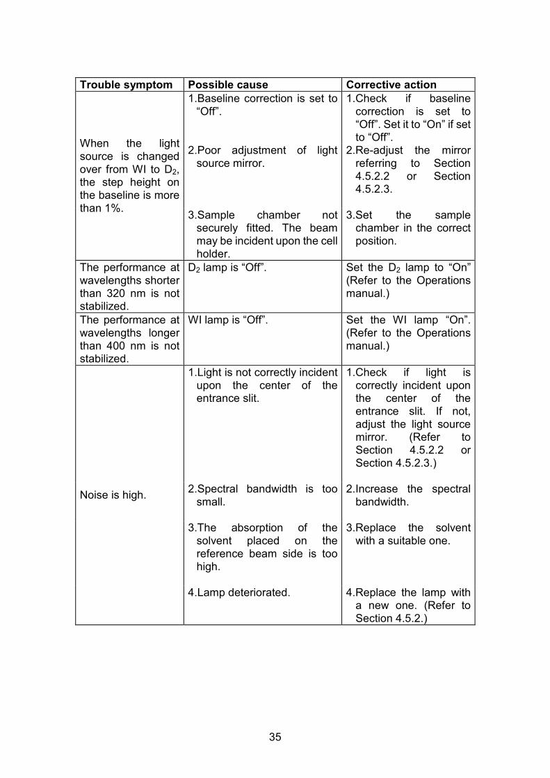
Trouble symptom Possible cause Corrective action
1.Baseline correction is set to “Off”.
1.Check if baseline correction is set to “Off”. Set it to “On” if set to “Off”.
2.Poor adjustment of light source mirror.
2.Re-adjust the mirror referring to Section 4.5.2.2 or Section 4.5.2.3.
When the light source is changed over from WI to D2, the step height on the baseline is more than 1%.
3.Sample chamber not securely fitted. The beam may be incident upon the cell holder.
3.Set the sample chamber in the correct position.
The performance at wavelengths shorter than 320 nm is not stabilized.
D2 lamp is “Off”. Set the D2 lamp to “On” (Refer to the Operations manual.)
The performance at wavelengths longer than 400 nm is not stabilized.
WI lamp is “Off”. Set the WI lamp “On”. (Refer to the Operations manual.)
1.Light is not correctly incident upon the center of the entrance slit.
1.Check if light is correctly incident upon the center of the entrance slit. If not, adjust the light source mirror. (Refer to Section 4.5.2.2 or Section 4.5.2.3.)
2.Spectral bandwidth is too small.
2.Increase the spectral bandwidth.
3.The absorption of the solvent placed on the reference beam side is too high.
3.Replace the solvent with a suitable one.
Noise is high.
4.Lamp deteriorated. 4.Replace the lamp with a new one. (Refer to Section 4.5.2.)

36

JASCO Corporation 2967-5, Ishikawa-machi, Hachioji-shi
TOKYO, JAPAN
Printed in Japan


