Definitions ....................................................................................................................................7 Attack Delay:........................................................................................................................ 7 PTT ANI repeat timer: ......................................................................................................... 7 Number of repeat emergency transmissions:........................................................................ 7 Time between emergency repeats: ....................................................................................... 7 Time out timer: ..................................................................................................................... 7 Open Microphone Monitor on Emergency TX time ............................................................ 7 Open Microphone Monitor on Emergency RX time ............................................................ 7 Send ID at beginning:........................................................................................................... 7 Send ID at end:..................................................................................................................... 8 TX Data Level:..................................................................................................................... 8 Sidetone with PTT ANI: ...................................................................................................... 8 Unkey courtesy tone:............................................................................................................ 8 Emergency TX warning tone: .............................................................................................. 8 Enable Keypad: .................................................................................................................... 8 Enable Manual Keypad DTMF ............................................................................................ 8 DTMF Keypad auto transmit ............................................................................................... 8 GE Star® format type........................................................................................................... 8 GE Star® PTT ID, Emergency ID ....................................................................................... 8 MDC-1200® PTT ID, Emergency ID.................................................................................. 9 DTMF character duration..................................................................................................... 9 DTMF inter-character duration ............................................................................................ 9 DTMF PTT ID, Emergency ID ............................................................................................ 9
What Is the VME-100 The Cimarron Technologies Model VME-100 is a plug-in ANI encoder module capable of PTT ANI and Emergency ANI in GE Star, MDC-1200 or DTMF signaling format in Vertex communications radios. The unit provides Automatic Numeric Identification of a specific radio transmitter each time the microphone press-to-talk (PTT) switch is activated. Emergency messages are sent by depressing the designated emergency button for greater than a programmed period. Manual DTMF generation is available as well as automatic ANI.
Capabilities • Identify every transmission source with the assigned ANI ID in
Signaling formats of MDC-1200, GE Star and DTMF
• Manual button press DTMF generation
• Programmable automatic radio key-up with DTMF keypad presses
• Programmable ANI debounce time limits data bursts during continued conversations
• “Go-ahead” beep sounds when ready for voice transmission
• Courtesy beep transmitted when radio is unkeyed
• Emergency message sent with emergency button press
• Programmable open microphone monitor during emergency
• Stuck microphone identification
• Time-Out-Timer with alert tone
• ANI sent at beginning, end or both
Chapter 1 Features 5
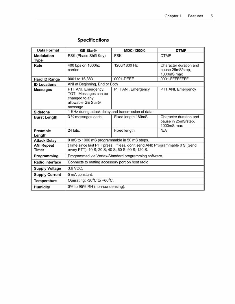
Specifications
Data Format GE Star® MDC-1200® DTMF Modulation Type
PSK (Phase Shift Key) FSK DTMF
Rate 400 bps on 1600hz carrier
1200/1800 Hz Character duration and pause 25mS/step, 1000mS max
Hard ID Range 0001 to 16,383 0001-DEEE 0001-FFFFFFFF ID Locations ANI at Beginning, End or Both Messages PTT ANI, Emergency,
TOT. Messages can be changed to any allowable GE Star® message.
PTT ANI, Emergency PTT ANI, Emergency
Sidetone 1 KHz during attack delay and transmission of data. Burst Length 3 ½ messages each. Fixed length 180mS Character duration and
pause in 25mS/step, 1000mS max
Preamble Length
24 bits. Fixed length N/A
Attack Delay 0 mS to 1000 mS programmable in 50 mS steps. ANI Repeat Timer
(Time since last PTT press. If less, don’t send ANI) Programmable 0 S (Send every PTT); 10 S; 20 S; 40 S; 60 S; 90 S; 120 S.
Programming Programmed via Vertex/Standard programming software. Radio Interface Connects to mating accessory port on host radio Supply Voltage 3.6 VDC. Supply Current 5 mA constant. Temperature Operating: -30oC to +60oC.
Humidity 0% to 95% RH (non-condensing).
6 Chapter 2 Programming
C H A P T E R 2 Programming
Programmable Parameters The following parameters are programmable using the Vertex/Standard CE-73 programming software. Default values are italicized in brackets to the right of the parameter
Attack Delay (N/A for end send) 0ms to 1000ms in steps of 50ms. [Default 300mS]
PTT ANI repeat timer (time since last PTT press. If less, don’t send PTT ANI) (0=send every PTT; 10s, 20s, 40s, 60s, 90s, 120s) [Default 0]
Number of repeat emergency transmissions. (1, 5, 10, 15, 20, forever) [Default =5]
Time between emergency repeats. (5s, 10, 20, 30s) [Default=10s]
Time out timer (30s, 60s, 90s, 120s) [Default: 60s]
Open Microphone Monitor on Emergency TX time (0s to 55s, 5s steps) [Default 0s]
Open Microphone Monitor on Emergency RX time (0s to 55s, 5s steps) [Default 0s]
Send ID at beginning (Y/N) [Default Yes]
Send ID at end (Y/N) [Default No]
TX Data Level (0,1,2,3) [Default 1]
Sidetone with PTT ANI (beginning send only) (Y/N) [Default Yes]
Unkey courtesy tone (Y/N) [Default No]
Emergency TX warning tone (Y/N) [Default No]
Enable keypad (Y/N) [Default Yes]
Enable Manual Keypad DTMF (Y/N) [Default Yes]
DTMF Keypad auto transmit (Y/N) [Default No]
GE Star® format type (A through P) [Default B]
GE Star® PTT ID (1 – 16383) [Default 9999]
GE Star® PTT Message value (0x00-0x7F) [Default 0x01]
GE Star® TOT ID (1 – 16383) [Default 9999]
GE Star® TOT Message value (0x00-0x7F) [Default 0x09]
GE Star® Emergency ID (1 – 16383) [Default 9999]
GE Star Emergency Message value (0x00-0x7F) [Default 0x07]
MDC-1200® PTT ID (1 – DEEE) [Default 1234]
Chapter 2 Programming 7
MDC-1200® PTT Message value (0x0000-0xFFFF) [Default 0x8001]
MDC-1200® Emergency ID (1 – DEEE) [Default 1234]
MDC-1200® Emergency Message value (0x0000-0xFFFF) [Default 0x8000]
DTMF character duration (25mS through 1000 mS in 25mS steps) [Default 50 mS)
DTMF inter-character duration (25 mS through 1000 mS in 25 mS steps) [Default 50 mS]
DTMF PTT ID (1 – FFFFFFFF) [Default = 11234]
DTMF Emergency ID (1 –FFFFFFFF) [Default = 71234]
Definitions Attack Delay: The period of time from when the user keys the radio and the data begins to be transmitted. This delay allows the communications system to stabilize and be ready for transmission.
PTT ANI repeat timer: Used to reduce the amount of data transmissions. If the selected time since the last PTT press is not exceeded, data is not transmitted with that PTT press.
Number of repeat emergency transmissions: Number of times that an emergency message is transmitted.
Time between emergency repeats: When in the emergency mode, if the number of repeat emergency transmissions is not “One”, this is the time that will be waited between emergency transmissions.
Time out timer: If the radio is held keyed up for greater than the selected time, the ID is transmitted and the radio is automatically unkeyed.
Open Microphone Monitor on Emergency TX time If not set to zero, once an emergency is activated, the radio will key up and transmit ambient noise for this period of time. It will then unkey and remain unkeyed for a programmed amount of time and then repeat the process. It will alternate between TX and RX throughout the emergency cycle. The length of the cycle is determined by the settings of “Number of repeat emergency transmissions” and “Time between emergency repeats”. If the value is set to zero, there will be no open microphone monitor.
Open Microphone Monitor on Emergency RX time If open microphone monitor on emergency TX time is not set to zero, the radio will remain unkeyed for this period of time between TX times.
Send ID at beginning: If programmed “Yes”, the ID will be transmitted when the user
8 Chapter 2 Programming
keys the radio.
Send ID at end: If programmed “Yes”, the ID will be transmitted when the user unkeys the radio.
TX Data Level: Changes the data output level in four steps. Enter a value between 0 and 3 that provides a data deviation that is just below radio voice deviation.
Sidetone with PTT ANI: If programmed “Yes”, a tone will sound through the local speaker to advise the user to hold off talking. Prevents “Voice syllable clipping” which could occur during data transmission.
Unkey courtesy tone: If programmed “Yes”, a tone will be transmitted when the user unkeys to inform the listener that they may now transmit.
Emergency TX warning tone: If programmed “Yes”, a warning tone will sound through the local speaker to advise the user that an emergency message is being transmitted.
Enable Keypad: If programmed “No”, keypad presses are ignored.
Enable Manual Keypad DTMF (Y/N) If enabled, DTMF tones will be generated when keypad buttons are pressed with the radio keyed. The associated tone continues to be transmitted until the button is released. The radio microphone is muted for the duration of the button press. Enabling this feature and not designating ANI type for the channel will permit manual DTMF generation without PTT ANI. The default is YES.
DTMF Keypad auto transmit (Y/N) If enabled, the radio will automatically go into transmit mode if keypad buttons are pressed and DTMF is generated. If this feature is enabled, ANI will be disabled. Additionally, after a button is released, the radio will remain keyed for one second to await further button presses. The length of the transmitted DTMF tone is the value programmed as “DTMF character duration”. The radio microphone is muted for the duration of the function. If PTT ANI transmission is required, this feature must be disabled and the user must manually key the radio while pressing buttons for DTMF transmission. The default is NO.
GE Star® format type (A through P) This selection defines which of the sixteen GE Star® formats are in use. The default is B.
GE Star® PTT ID, Emergency ID (1 – 16383) The actual maximum value depends on the GE Star® format type selected. Generally, the PTT ID and the Emergency ID
Chapter 2 Programming 9
in GE Star® are the same, however, they could be programmed different if desired. A radio cannot be programmed for an ID of 0 (zero). The default for both is 9999.
MDC-1200® PTT ID, Emergency ID (1 – DEEE) Generally, the PTT ID and the Emergency ID are the same, however, they could be programmed different if desired. A radio ID cannot contain the character F nor can it begin with the character E as these are defined as wildcards. The default for both 1234.
DTMF character duration (25 mS through 1000 mS in 25 mS steps) This timer is active for PTT and Emergency ANI and DTMF Keypad Auto transmit mode. Each ANI character is generated for this amount of time. The default is 50 mS.
DTMF inter-character duration (25 mS through 1000 mS in 25 mS steps) This timer is active only for PTT and Emergency ANI. The time selected is the silent gap between individual DTMF digit transmissions. The default is 50 mS.
DTMF PTT ID, Emergency ID (1 – FFFFFFFF) In DTMF signaling, the PTT ID and the Emergency ID are different so the base can determine what is an emergency message. Systems using dispatch consoles generally define a DTMF PTT ID as a number beginning with a 1 and DTMF Emergency ID’s begin with a 7. The default PTT ID is 11234 and the default emergency ID is 71234.
Memory Characteristics Programming parameters are stored in non-volatile memory and will be retained when the radio is turned off or when the battery is removed.
10 Chapter 3 Operation
C H A P T E R 3 Operation
Viewing the Programmed ID To review the programmed ID on the channel selected, press the # (pound) key. Press the # key again or wait five seconds to return to the channel information presentation.
PTT Operation On specified radio channels, with the press of the PTT button, The VME-100 disables the radio microphone and then transmits the ANI ID. While the radio is transmitting the data, a tone sounds in the local speaker to advise the user to hold off talking. After the data is transmitted, the PTT sidetone stops and the microphone is activated. The digital burst can be programmed to occur when the switch is first pressed, or when the switch is released, or at both times. If the burst is programmed for transmission when the PTT is released or the radio is on a non signaling channel, a short “go ahead” beep will be heard. When the PTT is released and transmission is over, a courtesy beep is transmitted to inform the listener that they can now transmit.
The PTT Sidetone and courtesy beep can be individually deactivated in personality programming.
To reduce the amount of data transmissions, data can be programmed to not occur during continuing conversations. A value can be selected for the time since the last PTT press. If the selected time is not exceeded in subsequent Key-ups, data is not sent. Programmable times are 0, 10s, 20s, 40s, 60s, 120s. [Default = 0]. If the time selected is 0 (zero), ANI will be sent with every PTT press.
Emergency Message An Emergency message transmission is activated whenever the designated emergency button is held down for greater than the programmed time.
The emergency message transmission will be repeated a programmed number of times with a programmed period between transmissions. The repeats will be transmitted regardless of radio status. Available times are as follows:
Number of repeat emergency transmissions. (1, 5, 10, 15, 20, forever) [Default = 5]. Time between emergency repeats. (5s, 10, 20, 30s) [Default=10s].
If desired, a warning tone can be sounded in the local speaker to advise the user that an emergency message has been sent.
In conjunction with a properly configured radio personality, the
Chapter 3 Operation 11
radio will change channels prior to sending the emergency message.
Emergency Message Open Microphone Monitor If this feature is enabled, when an emergency is activated, the radio will key up and transmit ambient noise for a programmed period of time. It will then unkey and remain unkeyed for a programmed amount of time and then repeat the process. It will alternate between TX and RX throughout the emergency cycle. The length of the cycle is determined by the settings of “Number of repeat emergency transmissions” and “Time between emergency repeats”. If the value is set to zero, there will be no open microphone monitor.
Time-Out-Timer and Stuck-Microphone The Time-Out-Timer feature terminates a transmission that is longer than the programmed time. Available times are 30s, 60s, 90s, 120s. [Default = 60s]. The radio will automatically unkey and a low frequency (500 Hz) tone will be heard in the local speaker for four seconds or until the radio is unkeyed. The value of the time-out-timer is programmable in the radio personality programming.
To permit identification of the offending radio, prior to un-keying the transmitter, the VME-100 will send the radio ID.
DTMF Operations The VME-100 is capable of generating DTMF tones in three modes.
Manual Keypad DTMF DTMF tones are generated when keypad buttons are pressed with the radio keyed. The DTMF tone continues to be transmitted until the button is released. The radio microphone is muted for the duration of the button press. This feature can be used on channels that use GE Star or MDC-1200 ANI signaling. Enabling this feature and not designating ANI type (or designating the channel as a non-signaling channel) for the channel will permit manual DTMF generation without PTT ANI.
DTMF Keypad auto transmit If enabled, the radio automatically goes into transmit mode when keypad buttons are pressed and DTMF is generated. If ANI is enabled, the auto transmit feature will be disabled. To activate the feature, the channel must be designated a signaling channel even though PTT ANI is disabled. Additionally, after a button is released, the radio will remain keyed for one second to await further button presses. The length of the transmitted DTMF tone is the value programmed as “DTMF character duration”. The radio microphone is muted for the duration of the function. If PTT ANI transmission is required, this feature must be disabled and the user must manually key the radio while pressing buttons for DTMF transmission.
DTMF ANI Typically, in DTMF ANI, the PTT ID and the Emergency ID are different so the base decoder can determine what is an emergency
12 Chapter 3 Operation
message. Systems using dispatch consoles generally define a DTMF PTT ID as a number beginning with a 1 and DTMF Emergency ID’s begin with a 7. The length of a DTMF character is programmable 25 mS through 1000 mS in 25 mS steps. The pause between DTMF characters is programmable 25 mS through 1000 mS in 25 mS steps. DTMF ANI can be programmed for up to eight digits.
Chapter 4 Technical Information 13
C H A P T E R 4 Technical Information
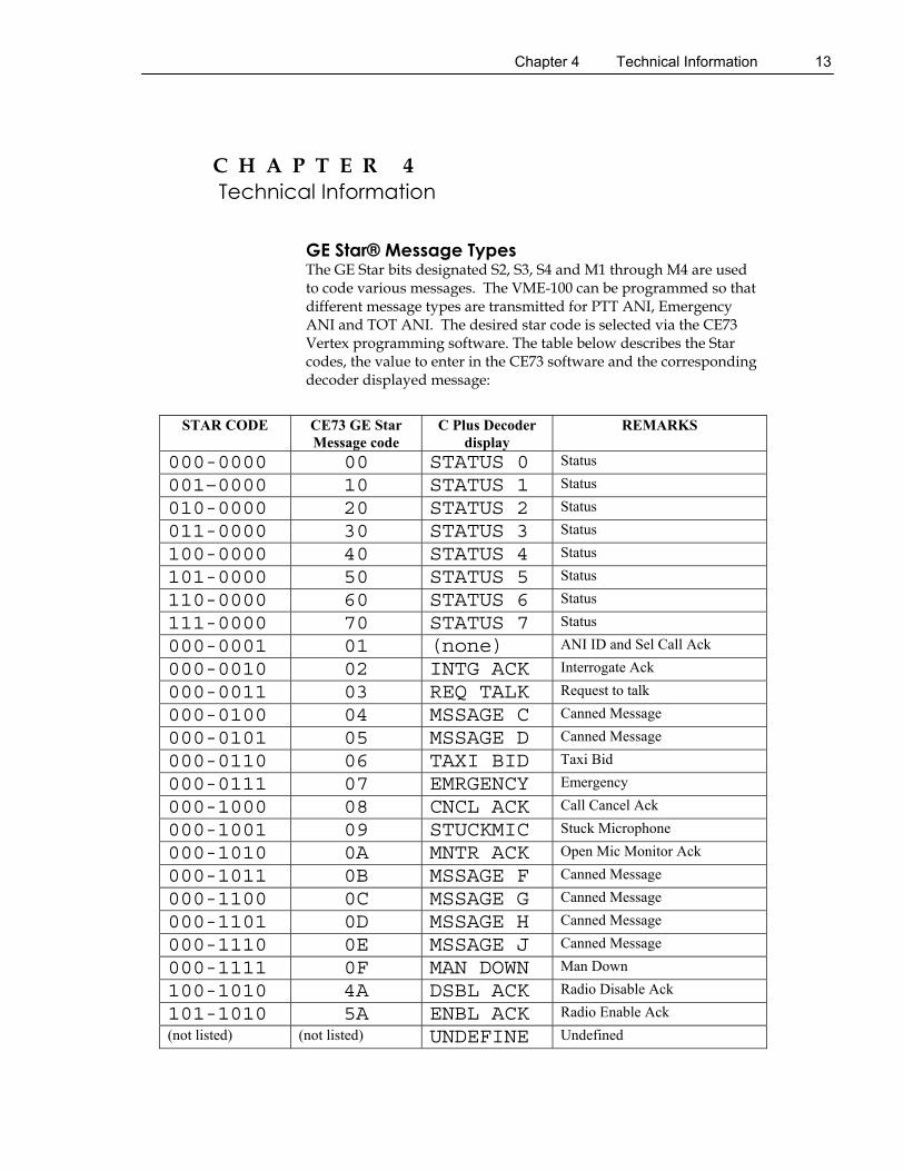
GE Star® Message Types The GE Star bits designated S2, S3, S4 and M1 through M4 are used to code various messages. The VME-100 can be programmed so that different message types are transmitted for PTT ANI, Emergency ANI and TOT ANI. The desired star code is selected via the CE73 Vertex programming software. The table below describes the Star codes, the value to enter in the CE73 software and the corresponding decoder displayed message:
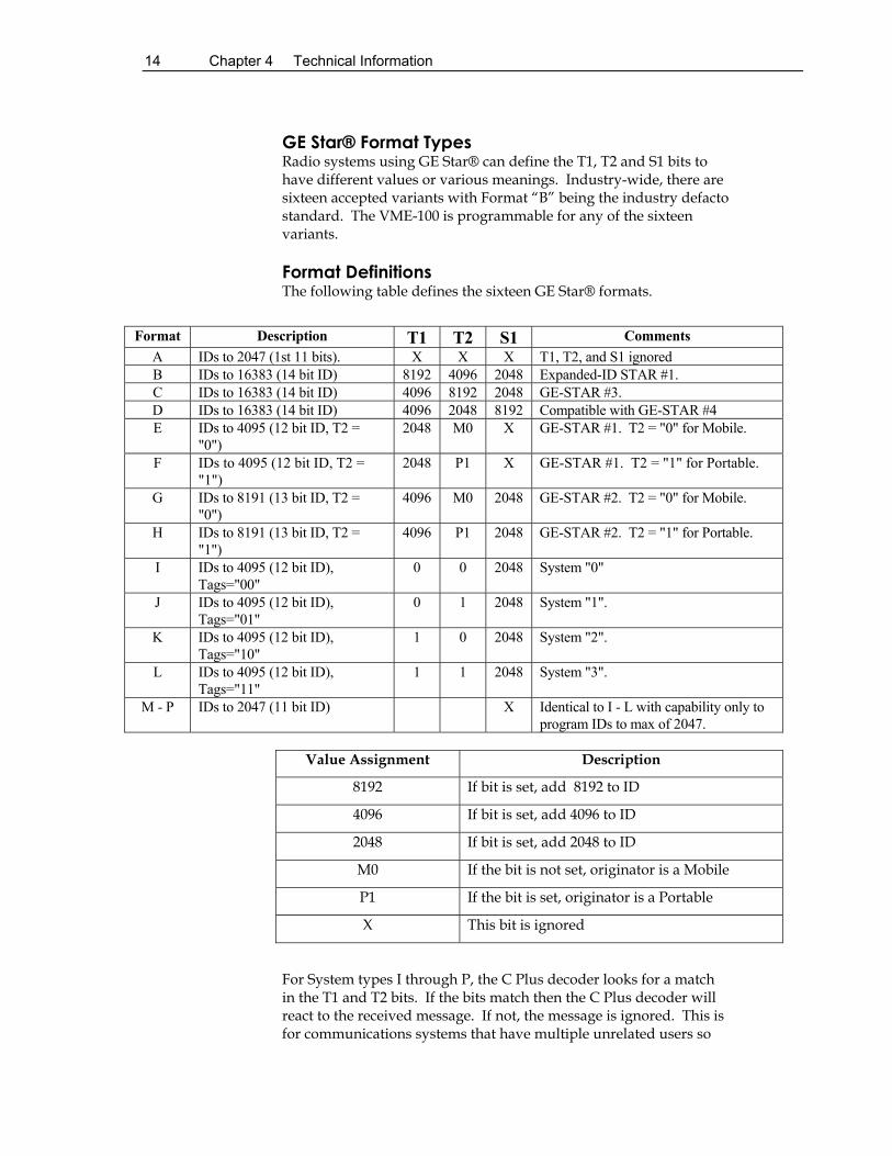
GE Star® Format Types Radio systems using GE Star® can define the T1, T2 and S1 bits to have different values or various meanings. Industry-wide, there are sixteen accepted variants with Format “B” being the industry defacto standard. The VME-100 is programmable for any of the sixteen variants.
Format Definitions The following table defines the sixteen GE Star® formats.
Format Description T1 T2 S1 Comments
A IDs to 2047 (1st 11 bits). X X X T1, T2, and S1 ignored B IDs to 16383 (14 bit ID) 8192 4096 2048 Expanded-ID STAR #1. C IDs to 16383 (14 bit ID) 4096 8192 2048 GE-STAR #3. D IDs to 16383 (14 bit ID) 4096 2048 8192 Compatible with GE-STAR #4 E IDs to 4095 (12 bit ID, T2 =
"0") 2048 M0 X GE-STAR #1. T2 = "0" for Mobile.
F IDs to 4095 (12 bit ID, T2 = "1")
2048 P1 X GE-STAR #1. T2 = "1" for Portable.
G IDs to 8191 (13 bit ID, T2 = "0")
4096 M0 2048 GE-STAR #2. T2 = "0" for Mobile.
H IDs to 8191 (13 bit ID, T2 = "1")
4096 P1 2048 GE-STAR #2. T2 = "1" for Portable.
I IDs to 4095 (12 bit ID), Tags="00"
0 0 2048 System "0"
J IDs to 4095 (12 bit ID), Tags="01"
0 1 2048 System "1".
K IDs to 4095 (12 bit ID), Tags="10"
1 0 2048 System "2".
L IDs to 4095 (12 bit ID), Tags="11"
1 1 2048 System "3".
M - P IDs to 2047 (11 bit ID) X Identical to I - L with capability only to program IDs to max of 2047.
Value Assignment Description
8192 If bit is set, add 8192 to ID
4096 If bit is set, add 4096 to ID
2048 If bit is set, add 2048 to ID
M0 If the bit is not set, originator is a Mobile
P1 If the bit is set, originator is a Portable
X This bit is ignored
For System types I through P, the C Plus decoder looks for a match in the T1 and T2 bits. If the bits match then the C Plus decoder will react to the received message. If not, the message is ignored. This is for communications systems that have multiple unrelated users so
Chapter 4 Technical Information 15
that different users do not see ID’s from other users.
16 Chapter 4 Technical Information
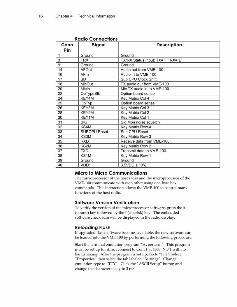
Radio Connections
Conn Pin
Signal Description
1 Ground Ground 3 TRX TX/RX Status Input: TX=”H” RX=”L” 9 Ground Ground 14 AFOut Audio out from VME-100 16 AFIn Audio in to VME-100 17 SD Sub CPU Clock Shift 18 MicOut TX audio out from VME-100 20 MicIn Mic TX audio in to VME-100 22 OpTypeStb Option board sense 24 KEY4M Key Matrix Col 4 25 OpTyp Option board sense 26 KEY3M Key Matrix Col 3 28 KEY2M Key Matrix Col 2 30 KEY1M Key Matrix Col 1 31 SIG Sig Mon noise squelch 32 KS4M Key Matrix Row 4 33 SUBCPU Reset Sub CPU Reset 34 KS3M Key Matrix Row 3 35 RXD Receive data from VME-100 36 KS2M Key Matrix Row 2 37 TXD Transmit data to VME-100 38 KS1M Key Matrix Row 1 39 Ground Ground 40 VDD1 3.5VDC ± 10%
Micro to Micro Communications The microprocessor of the host radio and the microprocessor of the VME-100 communicate with each other using one-byte hex commands. This interaction allows the VME-100 to control many functions of the host radio.
Software Version Verification To verify the version of the microprocessor software, press the # (pound) key followed by the * (asterisk) key. The embedded software check sum will be displayed in the radio display.
Reloading Flash If upgraded flash software becomes available, the new software can be loaded into the VME-100 by performing the following procedure.
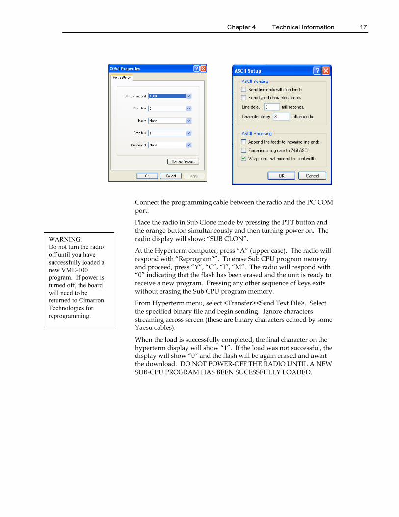
Start the terminal emulation program “Hyperterm”. This program must be set up for direct connect to Com 1 at 4800, N,8,1 with no handshaking. After the program is set up, Go to “File”, select “Properties” then select the tab labeled “Settings”. Change emulation type to “TTY”. Click the “ASCII Setup” button and change the character delay to 3 mS.
Chapter 4 Technical Information 17
WARNING: Do not turn the radio off until you have successfully loaded a new VME-100 program. If power is turned off, the board will need to be returned to Cimarron Technologies for reprogramming.
Connect the programming cable between the radio and the PC COM port.
Place the radio in Sub Clone mode by pressing the PTT button and the orange button simultaneously and then turning power on. The radio display will show: “SUB CLON”.
At the Hyperterm computer, press “A” (upper case). The radio will respond with “Reprogram?”. To erase Sub CPU program memory and proceed, press “Y”, “C”, “I”, “M”. The radio will respond with “0” indicating that the flash has been erased and the unit is ready to receive a new program. Pressing any other sequence of keys exits without erasing the Sub CPU program memory.
From Hyperterm menu, select <Transfer><Send Text File>. Select the specified binary file and begin sending. Ignore characters streaming across screen (these are binary characters echoed by some Yaesu cables).
When the load is successfully completed, the final character on the hyperterm display will show “1”. If the load was not successful, the display will show “0” and the flash will be again erased and await the download. DO NOT POWER-OFF THE RADIO UNTIL A NEW SUB-CPU PROGRAM HAS BEEN SUCESSFULLY LOADED.
18
C
hapt
er 4
T
echn
ical
Info
rmat
ion
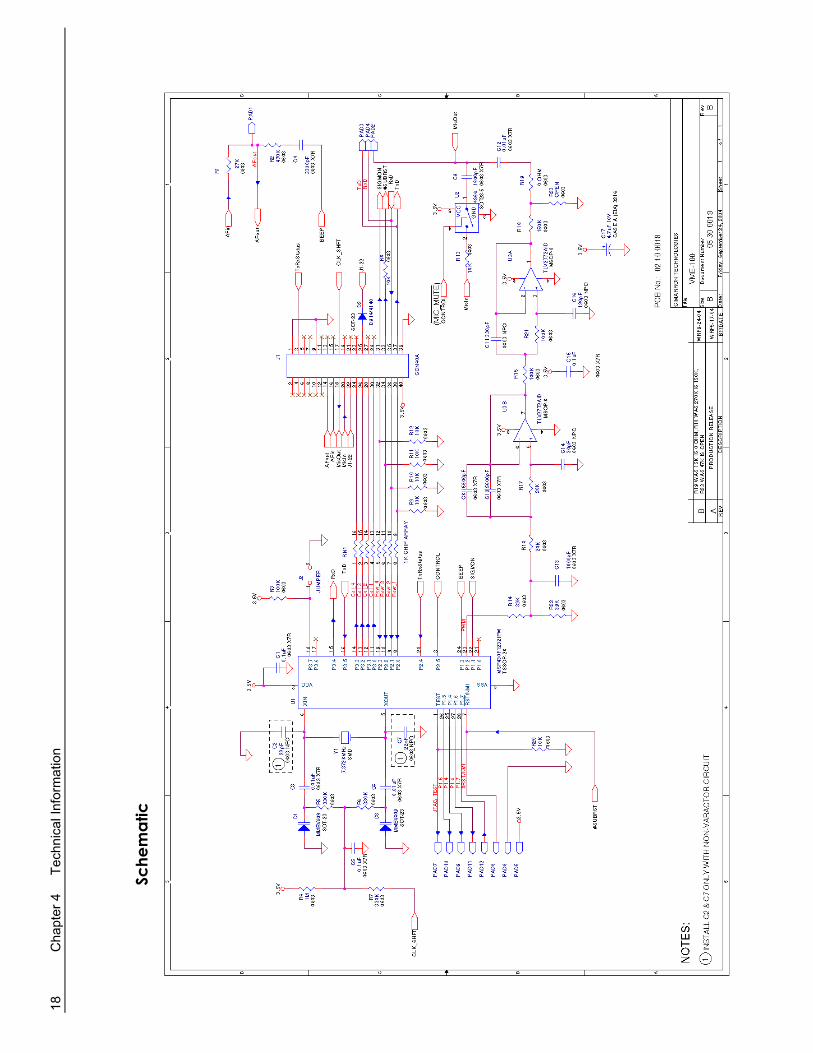
Sche
mat
ic
Cha
pter
4
Tech
nica
l Inf
orm
atio
n
1
9
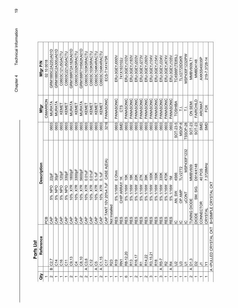
Parts
List
Q
ty
R
efer
ence
D
escr
iptio
n M
fgr
Mfg
r P/N
1
PC
B
C
IMA
RR
ON
02
10
0018
2
B C
2,7
CAP
5%
NPO
22
pF
0603
M
UR
ATA
G
RM
1885
C2A
220J
A01D
1
C
14
CAP
5%
NPO
30
pF
0603
M
UR
ATA
G
RM
1885
C2A
300J
A01D
1
C
16
CAP
5%
NPO
12
0pF
0603
KE
MET
C
0603
C12
1J5G
ACTU
1
C
11
CAP
5%
NPO
33
0pF
0603
KE
MET
C
0603
C22
1J5G
ACTU
2
C
9,13
C
AP
10%
X7R
18
00pF
06
03
MU
RAT
A
GR
M18
8R72
A182
KA01
D
1
C4
CAP
10
% X
7R
3300
pF
0603
KE
MET
C
0603
C33
2K5R
ACTU
2
C
8,10
C
AP
10%
X7R
56
00pF
06
03
MU
RAT
A
GR
M18
8R71
H56
2KA0
1D
2 A
C3,
6 C
AP
10%
X7R
0.
01uF
06
03
KEM
ET
C06
03C
103K
5RAC
TU
1
C12
C
AP
10%
X7R
0.
01uF
06
03
KEM
ET
C06
03C
103K
5RAC
TU
1 A
C5
CAP
10
% X
7R
0.1u
F 06
03
KEM
ET
C06
03C
104K
4RAC
TU
2 A
C1,
15
CAP
10
% X
7R
0.1u
F 06
03
KEM
ET
C06
03C
104K
4RAC
TU
1
C17
C
AP
TA
NT
10V
20%
4.7u
F C
AS
E A
(EIA
) 32
16P
AN
AS
ON
IC
EC
S-T
1AY
475R
1
R
23
Not
Inst
alle
d
1
R19
R
ES
5% 1
/16W
0
Ohm
06
03
PA
NA
SO
NIC
E
RJ-
3GE
YJ0
00V
1
R
N1
RES
C
HIP
AR
RAY
1K
SMD
C
TS
741X
1631
02J
6
R8-
12,2
0 R
ES
5% 1
/16W
10
K
0603
P
AN
AS
ON
IC
ER
J-3G
EY
J103
V
1
R13
R
ES
5%
1/1
6W
18K
06
03
PA
NA
SO
NIC
E
RJ-
3GE
YJ1
83V
2
R
16,1
7 R
ES
5% 1
/16W
20
K
0603
P
AN
AS
ON
IC
ER
J-3G
EY
J203
V
1
R1
RE
S
5% 1
/16W
27
K
0603
P
AN
AS
ON
IC
ER
J-3G
EY
J273
V
2
R14
,22
RES
5%
1/1
6W
39K
06
03
PA
NA
SO
NIC
E
RJ-
3GE
YJ3
93V
3
R
3,15
,21
RE
S
5% 1
/16W
10
0K
0603
PA
NAS
ON
IC
ER
J-3G
EY
J104
V
1
R18
R
ES
5%
1/1
6W
150K
06
03
PA
NA
SO
NIC
E
RJ-
3GE
YJ1
54V
3
A R
5-7
RE
S
5% 1
/16W
33
0K
0603
P
AN
AS
ON
IC
ER
J-3G
EY
J334
V
1
R2
RE
S
5% 1
/16W
47
0K
0603
P
AN
AS
ON
IC
ER
J-3G
EY
J474
V
1 A
R4
RE
S
5% 1
/16W
1M
06
03
PA
NA
SO
NIC
E
RJ-
3GE
YJ1
05V
1
U
2 IC
A
N. S
W.
4S66
S
OT-
23-5
TO
SH
IBA
TC
4S66
F(TE
85L)
1
U
3 IC
O
P A
MP
TL
V277
2 M
SO
P-8
T.
I. TL
V27
72ID
GK
R
1
U1
IC
uCO
NT
MSP
430F
1232
TS
SO
P-2
8 T.
I. M
SP43
0F12
32IP
W
2 A
D1,
3 TU
NIN
G D
IOD
E
MM
BV
609
SO
T-23
O
N S
EM
I M
MBV
609L
T1
1
D2
DIO
DE
S
M. S
IG.
D91
4/41
48
SO
T-23
FA
IRC
HIL
D
MM
BD41
48
1
J1
CO
NN
EC
TOR
40
PO
S
SM
D
AR
OM
AT
AXK5
S400
35P
1
Y1
CR
YS
TAL
7.
3728
MH
z S
MD
FO
X 21
9-7.
3728
-14
A
=P
ULL
ED
CR
YS
TAL
CK
T B
=SIM
PLE
CR
YS
TAL
CK
T
20 Chapter 4 Technical Information
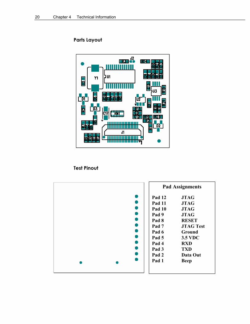
Parts Layout
Test Pinout
Pad Assignments
Pad 12 JTAG Pad 11 JTAG Pad 10 JTAG Pad 9 JTAG Pad 8 RESET Pad 7 JTAG Test Pad 6 Ground Pad 5 3.5 VDC Pad 4 RXD Pad 3 TXD Pad 2 Data Out Pad 1 Beep
Chapter 5 Product Support 21
C H A P T E R 5 Product Support
If you have any questions or comments about Cimarron products, please make use of our technical support hotline at (760) 738-3285.
WARRANTY Cimarron Technologies Corporation warrants this product to be free from defects in material and workmanship for a period of one year from date of shipment. If a malfunction occurs due to defective material or workmanship, the product will be repaired or replaced (Cimarron's discretion) without charge if returned to the factory This warranty does not apply to any failure or damage caused by accident, neglect, unreasonable use, improper installation, or to alterations or modifications to the unit. Nor does the warranty extend to damage incurred by force majeure (natural causes) such as lightning, fire, floods, or other such catastrophes, nor to damage caused by environmental extremes, power surges and/or transients Cimarron Technologies Corporation makes no other warranty, either expressed or implied, with respect to this product. Cimarron Technologies Corporation specifically disclaims the implied warranties of merchantability and fitness for a particular purpose. Some states or provinces do not allow limitations on how long an implied warranty lasts, so the above limitation or exclusion may not apply to you. The remedies provided herein are customer's sole and exclusive remedies. In no event shall Cimarron Technologies Corporation be liable for any lost profits, direct, indirect, special, incidental, or consequential damages, whether based on contract, tort, or any other legal theory.
GE Star emergency message value .....................6 GE Star message descriptions ...........................13 GE Star® emergency ID.....................................6 GE Star® format type .........................................6 GE Star® format types......................................14 GE Star® PTT ID ...........................................6, 8 GE Star® PTT message value.............................6 Go-ahead beep ....................................................4
Open microphone monitor ............................. 6, 7
P
Parts layout....................................................... 20 Product support ................................................ 21 Programming...................................................... 6 PTT .................................................................. 10 PTT ANI repeat timer .................................... 6, 7
R
Radio connections ............................................ 16 Reducing data transmissions ............................ 10 Repeat emergency transmissions.................. 6, 10 Review ............................................................. 10
S
Schematic ......................................................... 18 Send ID at beginning.......................................... 6 Send ID at end.................................................... 6 Sidetone with PTT ANI...................................... 6 Soft ID.............................................................. 10 Software version............................................... 16 Specifications ..................................................... 5 Stuck microphone identification ...................... 11 Sub clone mode................................................ 17
T
Technical Information...................................... 13 Test pinout ....................................................... 20 Time between emergency repeats .......6, 7, 10, 11 Time out timer.......................................... 6, 7, 11
INDEX 23
U
Unkey courtesy tone ...........................................6 Upgrading flash.................................................16