READ & SAVE THESE INSTRUCTIONS. This manual contains operating information and should be left with the unit. Model VS--D Steam Room Unit Installation & Operating Manual Edition 1.2.0. Installation in countries covered by EC Directives: This product meets the requirements of the RoHS Directive 2002/95/EEC This product will meet the requirements of the Low Voltage Safety Directive 2006/95/EEC and the EMC Directive 2004/108/EEC when installed in accordance with the instructions contained in this manual. Failure to comply with these instructions may invalidate the manufacturer's warranty or any certificate/declaration of conformance requested to be supplied with the unit.
Transcript
READ & SAVE THESE INSTRUCTIONS.
This manual contains operating information and should be left with the unit.
Model VS--D
Steam Room Unit
Installation & Operating Manual
Edition 1.2.0.
Installation in countries covered by EC Directives:
This product meets the requirements of the RoHS Directive 2002/95/EEC
This product will meet the requirements of the Low Voltage Safety Directive 2006/95/EEC
and the EMC Directive 2004/108/EEC when installed in accordance with the instructions
contained in this manual.
Failure to comply with these instructions may invalidate the manufacturer's warranty or any
certificate/declaration of conformance requested to be supplied with the unit.
Section General Page 2 of 24 14 Jun 2011
Section 1 Page 3 of 24 14-Oct-10
Table of Contents Important Installation Points .................................................................................................. 4
Important Electrical Connection Items ................................................................................... 4
Important Maintenance Items ................................................................................................ 4
9.0 Trouble-shooting Check List ..................................................................................... 22
Section 1 Page 4 of 24 14 Jun 2011
Important Installation Points The unit must be installed to comply with national regulations and/or codes of practice. A qualified electrician must carry this out.
Ensure at least 1000 mm clear front access to the electrical and steam sections.
Do not locate the cabinet where the ambient temperature around the unit could
exceed 35º C; or fall below 5º C e.g., an unventilated roof mounted enclosure – see
minimum space / ventilation requirements page 7. * If below 5º C Frost protection kit
required.
Do not locate the cabinet where a ladder is required for service access as this could
make servicing and cylinder service or exchange hazardous.
Make sure steam line(s) have adequate slope (min 12%) for condensate drainage and use condensate separators if the pipe is lower than the unit. Provide adequate support to prevent sags developing in flexible steam lines, which can fill with water and create a "trap".
Do not locate vented drain directly under the cabinet.
Important Electrical Connection Items Before commissioning the unit, check that all electrical (power) connections - including those at the terminals and contactor are tight.
The Vapac transformer must not be used to power other equipment.
To comply with EMC aspects see recommendations on page 10.
Do not mount the unit close to a source of strong electromagnetic emissions, such as
a variable speed motor drive, Kva transformer, or 'UPS' unit.
A minimum gap of 2 meters must be maintained between the unit and such devices.
Larger output devices may require an increased gap distance, depending on the
nature of screening / filtration measures fitted to the device.
Important Maintenance Items Only a qualified electrician should carry out maintenance. The boiler contains hot water, and must be drained before any maintenance is carried out on the steam section. This should be done prior to isolating the power, and removing the front access panel ESD SENSITIVE DEVICES USED ON PCB. ENSURE ANTI-STATIC PRECAUTIONS ARE TAKEN WHEN REMOVING OR REPLACING PCB’S.
Section General Page 5 of 24 14-Oct-10
1.0 Installation
Do‟s
Do mount the unit as close to the steam distribution pipe(s) as possible. Do mount the unit at a height convenient for reading the display window. Do ensure adequate side ventilation (min 80 mm). Do ensure adequate service access to the front of the unit (min 1000 mm). Do ensure adequate service access below the unit (min 1000 mm). Do ensure that the holes in the rear top panel remain unobstructed to allow a free flow of air. Do use the marking on the side of the carton as a template to mark the mounting hole positions. Do remove the cylinder, if necessary, to access the mounting holes in the back of the steam section. Do use M6 projecting type wall bolts or equivalent to mount the unit in position. Don’ts Don’t mount the unit close to sources of strong electro-magnetic emissions e.g. variable speed lift
motor drives, kVa transformers etc. Don’t mount the unit in an unventilated enclosure. Don’t mount in a position requiring ladder access to the unit. Don’t mount the unit behind a false ceiling or other situation where an unusual malfunction (e.g. water
leak) would cause damage. Don’t mount the unit in an area which will be hosed down. Don’t install the unit where the ambient temperature can exceed 35°C; or fall below 5
°C.
Don’t mount the unit inside a cold-room or other place where temperature and humidity conditions can
cause condensation on electrical components. Don’t mount the unit where the sound of a contactor opening/closing and water flow in a pipe would
be unacceptable e.g. libraries, private apartments, etc
Section 1 Page 6 of 24 14 Jun 2011
1.1 Vapac VS unit dimensions
Cabinet Sz 1 (9 – 18 kg/h Models)
Left:
Top View Showing Steam O/let
position and wall mounting
points.
Below: Side View showing wall
mounting points.
Left:
Bottom View Showing
“F” (Feed connection) ¾” BSP
male connection for flexible
hose provided with unit.
“D” (Drain connection)
35 mm pipe.
Section 1 Page 7 of 24 14-Oct-10
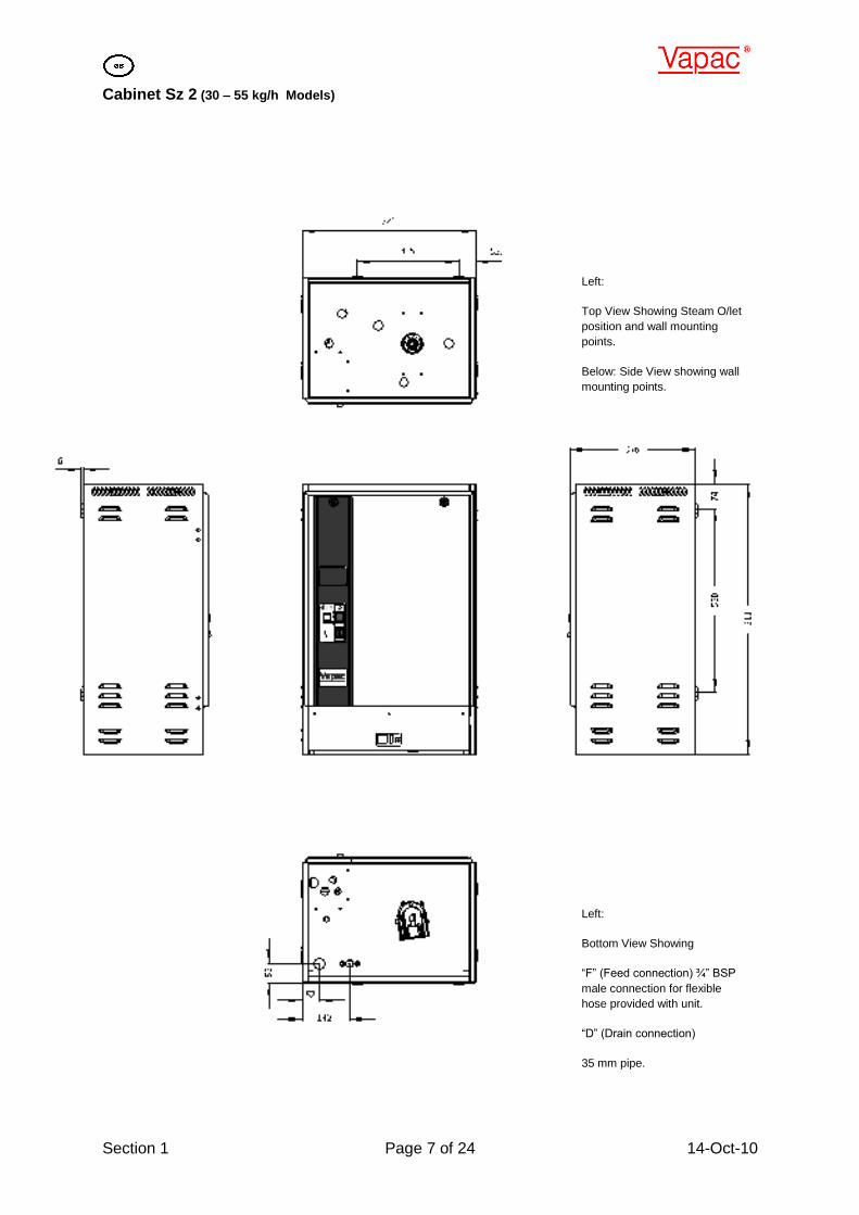
Cabinet Sz 2 (30 – 55 kg/h Models)
Left:
Top View Showing Steam O/let
position and wall mounting
points.
Below: Side View showing wall
mounting points.
Left:
Bottom View Showing
“F” (Feed connection) ¾” BSP
male connection for flexible
hose provided with unit.
“D” (Drain connection)
35 mm pipe.
Section 1 Page 8 of 24 14 Jun 2011
1.2 VS--D weights
The unit dry weight is the delivered unit with no water in the unit, the wet weight is the operational
weight when the unit is running.
1.3 Positioning the steam pipes
Do's
Do use Vapac steam hose or well insulated copper pipe
Do keep steam hose as short as possible (under 2m for max efficiency).
Do arrange to have a vertical rise immediately over the unit of 300mm
Do inject the essence into the steam line below the level of the cylinder and ensure that it can flow
freely out with the flow of steam. Any restrictions in flow will result in the essence solidifying and
causing a restriction to flow of steam.
Do add extra insulation to steam hose for longer runs (2m-5m) and in cold ambient conditions to avoid
excess condensate and reduction in delivered output.
Don'ts
Don't allow steam hose to develop kinks or sags.
Don't include horizontal runs or 90o elbows in the steam line.
Don’t reduce the diameter of the 55mm steam line unless split to two 35mm lines
Vapac model Dry Kg Wet Kg Steam Hose
VS18D 39 65.5 35mm
VS30D 40 66.5 55mm
VS45D / VS55D 45 72 55mm
Section 1 Page 9 of 24 14-Oct-10
Section 2 Page 10 of 24 14 Jun 2011
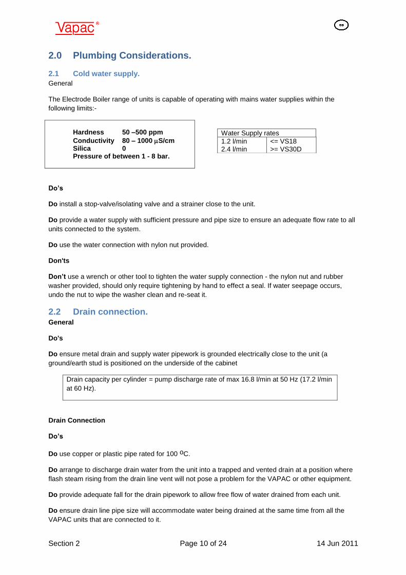
2.0 Plumbing Considerations.
2.1 Cold water supply.
General
The Electrode Boiler range of units is capable of operating with mains water supplies within the
following limits:-
Hardness 50 –500 ppm
Conductivity 80 – 1000 S/cm Silica 0 Pressure of between 1 - 8 bar.
Do’s
Do install a stop-valve/isolating valve and a strainer close to the unit.
Do provide a water supply with sufficient pressure and pipe size to ensure an adequate flow rate to all
units connected to the system.
Do use the water connection with nylon nut provided.
Don'ts
Don’t use a wrench or other tool to tighten the water supply connection - the nylon nut and rubber
washer provided, should only require tightening by hand to effect a seal. If water seepage occurs,
undo the nut to wipe the washer clean and re-seat it.
2.2 Drain connection. General
Do's
Do ensure metal drain and supply water pipework is grounded electrically close to the unit (a
ground/earth stud is positioned on the underside of the cabinet
Drain capacity per cylinder = pump discharge rate of max 16.8 l/min at 50 Hz (17.2 l/min
at 60 Hz).
Drain Connection
Do’s
Do use copper or plastic pipe rated for 100 oC.
Do arrange to discharge drain water from the unit into a trapped and vented drain at a position where
flash steam rising from the drain line vent will not pose a problem for the VAPAC or other equipment.
Do provide adequate fall for the drain pipework to allow free flow of water drained from each unit.
Do ensure drain line pipe size will accommodate water being drained at the same time from all the
VAPAC units that are connected to it.
Water Supply rates
1.2 l/min 2.4 l/min
<= VS18 >= VS30D
Section 3 Page 11 of 24 14-Oct-10
3.0 Electrical Connections
3.1 Power Supply Connection The wiring to the Vapac should be carried out by a qualified electrician. The external over-current
protection and wiring should comply with the appropriate Regulations and Codes of Practice.
IMPORTANT: A fused disconnect/isolator or MCB should be fitted so as to disconnect the supply
from all electrodes simultaneously. This must be sized to suit the total maximum phase/line current of
the unit and should be located adjacent to the unit and be within easy reach and readily accessible.
The units can be connected for single or 3 phase operation and should be connected as shown
below:
Three Phase connection: Single Phase connection
3.2 Control Connections The unit is supplied with all the required control connections made – all that is required is that the
temperature sensor that is pre-wired into the controller needs to be run such that it senses the
temperature inside the steam room. Should a remote enable or time switch be required the link fitted
across terminals 9 & 10 should be removed and the enable/time switch be wired in its place (such
that terminals 9 & 10 are connected together when the unit is required to operate and not connected
when the unit is required not to run).
Section 3 Page 12 of 24 14 Jun 2011
Additionally volt-free contacts are provided on terminals 1 + 2 and 3 + 4.
Terminals 1 & 2 are connected to a switch (mounted on the front panel, to enable a lighting circuit to
be operated from the unit, and terminals 3 & 4 are connected to an auxiliary contact on the contactor
(this is enabled whenever the unit is providing steam) which may be used to control the essence
pump circuitry.
The unused fuse terminal (F3) is connected to supply L1, and is provided as a convenient supply to
power the lighting circuit should this be required. Please note that no fuse is supplied or fitted to this
terminal and should be sized and provided by whoever is designing/building/supplying the steam
room.
Section 4 Page 13 of 24 14-Oct-10
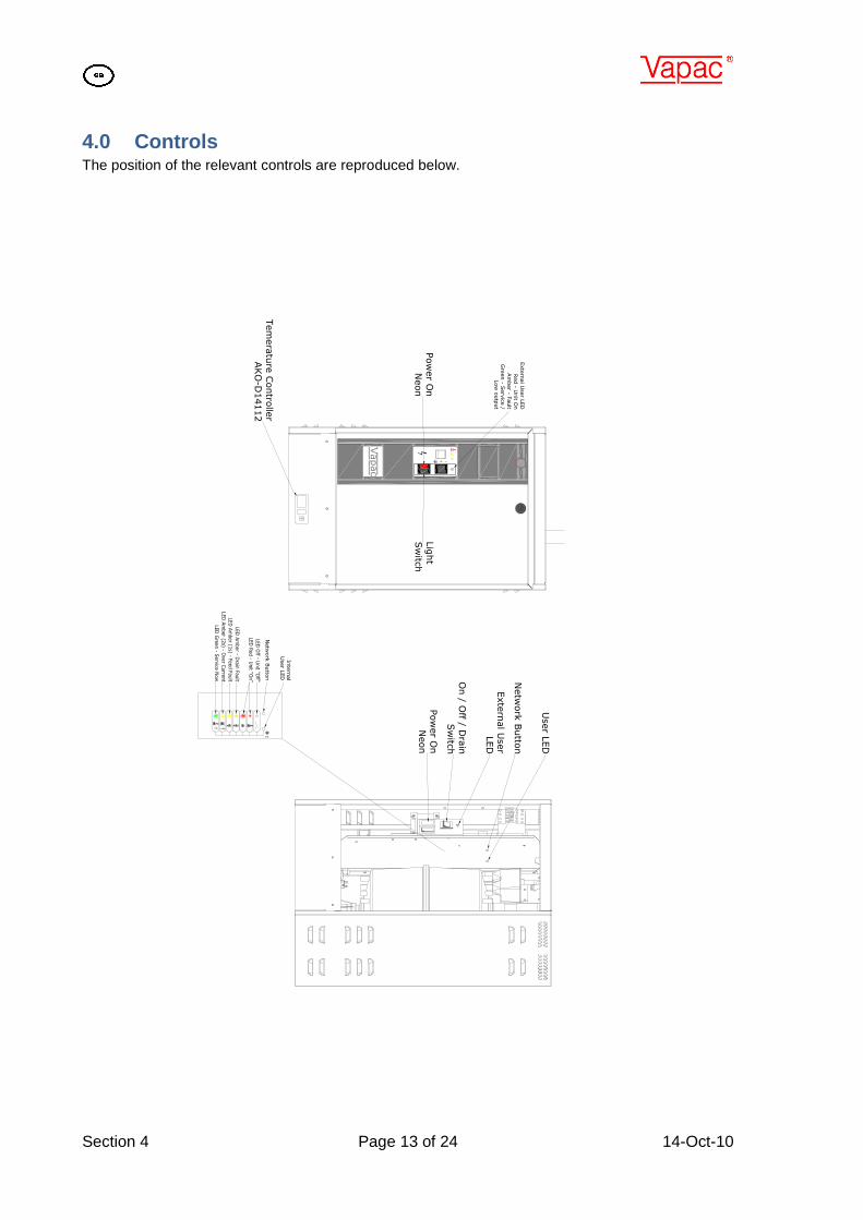
4.0 Controls The position of the relevant controls are reproduced below.
1
Vapac
0 I
User L
ED
Netw
ork
Butto
n
Exte
rnal U
ser
LED
Pow
er O
n
Neon
On / O
ff / Dra
in
Sw
itch
Inte
rnal
User L
ED
Netw
ork
Butto
n
Exte
rnal U
ser L
ED
Red - U
nit O
n
Am
ber - F
ault
Gre
en - S
erv
ice /
Low
outp
ut
Pow
er O
n
Neon
Lig
ht
Sw
itch
Tem
era
ture
Contro
ller
AKO
-D14112
Section 5 Page 14 of 24 14 Jun 2011
5.0 Status Indications
User LEDs
User LED State Description
1
RED Flashing
2 second period
Unit initialising.
IF REMAINS IN THIS STATE, THEN UNIT DOES NOT HAVE A VALID UCP1
FITTED.
Prior to the start of the initialisation process, the LEDs will flash Green, Red, Amber
repeatedly for 10 seconds to check that the LEDs are operating correctly.
Remedy:
1 Check that UCP1 is fitted to plug fitted to CR4 pins 7 & 8.
Section 5 Page 15 of 24 14-Oct-10
5.1 Normal Run / Standby / Start-up – No User Intervention Required
User LEDs being off, RED or RED Flashing refer to following table.
User LEDs Description
1 OFF Unit in shutdown.
2 OFF
Unit in standby
3
Green Amber
Flashing Variable
RED Flashing
Variable Period or ON
Unit in Startup.
Unit Online.
The above are purely indications of the current state of the unit and require no action
from the operator.
When the state changes, the indication will automatically change.
Section 5 Page 16 of 24 14 Jun 2011
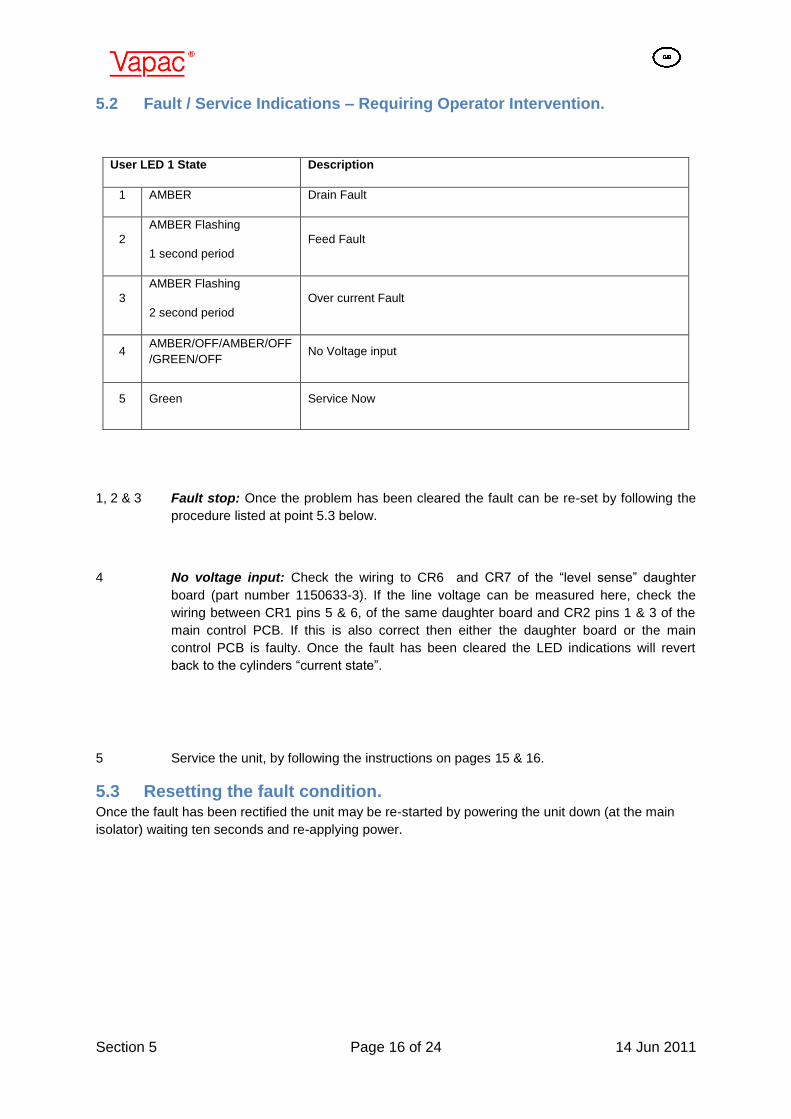
5.2 Fault / Service Indications – Requiring Operator Intervention.
1, 2 & 3 Fault stop: Once the problem has been cleared the fault can be re-set by following the
procedure listed at point 5.3 below.
4 No voltage input: Check the wiring to CR6 and CR7 of the “level sense” daughter
board (part number 1150633-3). If the line voltage can be measured here, check the
wiring between CR1 pins 5 & 6, of the same daughter board and CR2 pins 1 & 3 of the
main control PCB. If this is also correct then either the daughter board or the main
control PCB is faulty. Once the fault has been cleared the LED indications will revert
back to the cylinders “current state”.
5 Service the unit, by following the instructions on pages 15 & 16.
5.3 Resetting the fault condition. Once the fault has been rectified the unit may be re-started by powering the unit down (at the main
isolator) waiting ten seconds and re-applying power.
User LED 1 State Description
1 AMBER Drain Fault
2
AMBER Flashing
1 second period
Feed Fault
3
AMBER Flashing
2 second period
Over current Fault
4 AMBER/OFF/AMBER/OFF
/GREEN/OFF No Voltage input
5 Green Service Now
Section 6 Page 17 of 24 14 Jun 2011
6.0 Cylinder Exchange
Cylinder Life
The water hardness and the humidity demand at site will determine the effective life of a steam
cylinder. Units located in areas with naturally soft waters will experience the longer cylinder life,
possibly upwards of 12 months in calendar terms. With hard waters, a more frequent cylinder
exchange must be expected and cylinder exchange 2 or 3 times a year can be the average situation.
The normal scaling up of the Vapac steam cylinder is outside the VAPAC warranty.
6.1 Procedure for Cylinder Exchange
1. With power connected to the unit operate the Manual Drain switch and empty the steam cylinder.
2. Disconnect the VAPAC from the incoming electrical supply by means of the external disconnect
switch.
3. Remove the lockable door to the cylinder chamber and carefully ease off the electrode caps.
4. Loosen the hose clip and disconnect the steam hose from the top of the steam cylinder.
5. Using a twisting movement, lift the cylinder clear of its seating in the feed/drain manifold and
carefully remove the used cylinder from the unit.
6. Inspect the feed/drain manifold to ensure this is clear of sediment.
7. The drain pump can be removed for inspection/cleaning. By following the instructions for the drain
pump removal and cleaning below.
8. With the pump back in position after cleaning, insert the cylinder into the feed / drain manifold,
pushing it down firmly, and reconnect the steam hose.
9. The electrode caps must be reconnected in the same sequence in accordance with the details on
the collar supplied with the new cylinder.
10. The VAPAC unit is supplied with electrode cables routed to avoid contact with the removable door.
After a cylinder exchange, it is important to replace the cables as close as possible to their original
route.
Vapac Cleanable cylinders
Cleanable versions of the Vapac cylinders are available which can be opened to allow removal of
loose scale deposit. The cylinder designs are the same but instead of a welded join, the two parts are
brought together by a seal and two clamping rings with quick-release fasteners.
To order the equivalent cleanable cylinder use the same code but substitute the letters CC instead of
CM or CD.
When servicing a cleanable cylinder take it to a service area where it is convenient to open it and to
dispose of the contents. When cleaning out loose material also remove any build-up on the end of the
short "cylinder full" electrode. Make sure the slotted strainer is clean, intact and in place. When re-
Section 6 Page 18 of 24 14 Jun 2011
assembling, use a new seal and make sure mating surfaces are free of scale particles as they will
prevent a perfect seal and cause leaks.
Note 1: Do not touch an operating cylinder of this type in case there is a leak allowing water at mains
voltage to seep out.
Note 2: Do not interfere with the electrodes, if they are badly eroded and/or the internal positioning
ring is free, a new cylinder should be used.
6.2 Service and Maintenance
As the operation of the Vapac is entirely automatic, it normally requires no attention on a day-to-day
basis. General cleaning and maintenance of the component parts of the Vapac are recommended at
intervals of about one year, but this is largely dependent upon the frequency of its use and the quality
of the water supply. Where the Vapac is part of an air-conditioning system being serviced regularly,
the Vapac should be inspected at the same time.
6.2.1 Feed Valve with Strainer
The nylon bodied solenoid valve incorporates a small nylon strainer which is a push fit in the 3/4" inlet
of the valve. With a new plumbing installation, residual loose solid material in the pipework could
partially block the strainer after start-up. If for this or any other reason a restriction of the water flow is
suspected (outside of supply pressure considerations), it would be possible to clean the strainer as
follows:-
Turn off the water supply to the Unit.
Undo the nylon nut connecting the flexible connection to the valve inlet.
The strainer can be removed using „long-nosed‟ pliers to grip the center
flange provided on the strainer for this purpose.
Withdraw the strainer.
Wash and replace it.
Reconnect and turn on water supply.
Reconnect electrical supply to allow unit to operate.
Note: Always replace the strainer after cleaning as it is required to
prevent material lodging in the valve seat or blocking the small flow
control restrictor which is fitted in the valve.
Valve with flow restrictor
3/4 Nylon nut with washer as
part of flexible connector
Strainer
Section 6 Page 19 of 24 14 Jun 2011
6.2.2 Drain Pump
The pump is a sealed unit and should not be dismantled. Instructions for removal /
replacement are as follows.
1) Place a bucket below the pump, to catch any
water remaining in the housing or pipework.
2) Remove the two screws holding the pump cover
& lift clear.
3) Undo the three screws holding the pump body
to the feed & drain manifold, and remove it - any
water trapped in the pump will be released at this
point.
4) Fit the replacement pump by following the above
steps in reverse order. Ensuring that the O-ring
surrounding the impeller housing is correctly
seated, and that it mates correctly with the feed /
VS18D is fitted with a standard UCP for 18kg/13.48kW. UCP‟s, for 9kg/6.75kW, 12kg/9kW and 15kg/11.25kW, supplied cable tied for lower duties.
8.0 Circuit Diagram
80
81
82
PE N
A1
A1
1A1
1A3A1
A2
13
4 2
80
81
T2
A3
5
6
82
89
81
89
E1
E2
E3
A3A2
BROWN
BLACK
Eart
h
Grey
Grey
Violet
Violet
Cylinder
3 Phase, N & PE
Two Electrode cylinder E1 & E3 Three Electrode cylinder E1 E2 & E3
21
Gre
y
N Blue
32Voilet
8
8
Auto
run
Off
Dra
in
Part
Num
ber
1150655
CR3CR5
CR8
2
1
3
4
6
5
3
4
2
1
CR1
1095 6
55Violet
CR4
50
49
48
47
46
44
43
42
41
10
51
21 Brown
10
9Pink
Pink
White
Violet
White
Voilet 5
6
33
31
Violet
Pink
Violet
Pink
Violet
Voilet
Pink
Voilet
Pink
Pink
PUMPDRAINP1
200
415
380
230
115
0
29F1
2A
A1
20
29
20
Gre
y
Isolated wind
24 v 50 VA
Grey
Red
9v AC
0v AC
H10
20
29Red
Solenoid
WaterFeed
Valve
CYL 1
Y1A
K1
0v
24v
0v DO1
24v DO1
24v DO3
0v DO3
0v DO2
24v DO2
DI COM
DI 1
24v IN
24v OUT
DO 5
DO 4
DI 3
DI 2
AI 3 IN
AI 2 IN
AI 1 IN
AI 1&2 Ref
5 v out
DO 6 0v
DO 4&5com
11
12
1
2
3
4
6
5
7
8
9
10
8
7
6
5
3
4
2
1
12
11
10
9
CR2
fourresistive inputs
0V
Brown
BLACK
Grey
Grey
DAUGHTER BOARD
Part Number 1150633-3
Vio
let
29
22
89
81
55
51
42
41
31
32CR6
CR7
CR2CR4
47
48
N
F3
1 2 3 4
22F2
2A
A3
A2
A3
20 Grey
1 2 3 4 5 6 7 8 9 10 11
24V ~
0V ~Sensor
AKO-D14112 Temperature Controller
Temperature Sensor
N
N
Vapac Humidity Control Ltd
Fircroft WayEDENBRIDGE
Kent TN8 6EZ England
+44(0)1732 863447
VapacTitle:
A3Drawing Number:
LZD608
Fuse for lighting circuit
if required.
Volt free switched outputs
Trms 1 & 2 for lighting circuit
Trms 3 & 4 contactor Auxfor Essence pump circuit.
When operating unit on single phase & neutral Supply:
Connect L1 to A1 & Neutral to A3 (Link terminals A3 & N).
E4
E5
E6
Six Electrode cylinder E1 E2 E3 E4 E5 & E6
Section 9 Page 22 of 24 14 Jun 2011
9.0 Trouble-shooting Check List
Preliminary Symptom
Power-On Neon – Off Symbol-LED – Off
- Use manual drain option to check pump operation
Check/Cause/Remedy
- Check main power is connected and switched on.
- Check power supply fuses.
Power-On Neon – On Symbol-LED – On
- Check if security circuit is open circuit
- Check 24V 3.15A fuse mounted on the Vapanet controller PCB 1150655
Automatic STOP – Feed Fault indicated.
Possibilities
Water is not connected
Water connected but not
reaching cylinder
Water in cylinder and
overflowing
Checks
- Check water stop valve is open.
- Check internal Vapac hose connections for a leak.
- Check internal hoses for kinks or obstructions.
Automatic Stop – Drain Fault indicated.
Possibilities
Drain pump function
impaired
Cylinder O/Let Blocked
Checks
- If pump will not function, empty cylinder by disconnecting the water supply hose between the tundish and the cylinder (at the tundish fill-cup) and lowering it to drain the water into a bucket. Remove, dismantle and clean pump.
- Check un-block drain hoses
Unit On-Line but inadequate or no steam production.
Possibilities
Contactor not made
Cylinder scaled up.
Checks
- Contactor coil, Control PCB. - Cylinder Inspection (replace if necessary).
Made in England by:
Vapac Humidity Control Ltd.
0410272
14th June 2011
Vapac Humidity Control Ltd. reserve the right to change the design or
specification of the equipment described in this manual without prior notice.